

Page 1

User Manual
EKI-1360-BE Series
1/2-port RS-232/422/485 to
802.11a/b/g/n WLAN Serial
Device Servers
Page 2

Copyright
Part No. Edition 1
Printed in Taiwan September 2018
The documentation and the software included with this product are copyrighted 2018
by Advantech Co., Ltd. All rights are reserved. Advantech Co., Ltd. reserves the right
to make improvements in the products described in this manual at any time without
notice. No part of this manual may be reproduced, copied, translated or transmitted
in any form or by any means without the prior written permission of Advantech Co.,
Ltd. Information provided in this manual is intended to be accurate and reliable.
However, Advantech Co., Ltd. assumes no responsibility for its use, nor for any
infringements of the rights of third parties, which may result from its use.
Acknowledgments
Intel and Pentium are trademarks of Intel Corporation.
Microsoft Windows and MS-DOS are registered trademarks of Microsoft Corp.
All other product names or trademarks are properties of their respective owners.
Product Warranty (5 years)
Advantech warrants to you, the original purchaser, that each of its products will be
free from defects in materials and workmanship for five years from the date of
purchase.
This warranty does not apply to any products which have been repaired or altered by
persons other than repair personnel authorized by Advantech, or which have been
subject to misuse, abuse, accident or improper installation. Advantech assumes no
liability under the terms of this warranty as a consequence of such events.
Because of Advantech’s high quality-control standards and rigorous testing, most of
our customers never need to use our repair service. If an Advantech product is
defective, it will be repaired or replaced at no charge during the warranty period. For
out of-warranty repairs, you will be billed according to the cost of replacement
materials, service time and freight. Please consult your dealer for more details.
If you think you have a defective product, follow these steps:
1. Collect all the information about the problem encountered. (For example, CPU
speed, Advantech products used, other hardware and software used, etc.) Note
anything abnormal and list any on-screen messages you get when the problem
occurs.
2. Call your dealer and describe the problem. Please have your manual, product,
and any helpful information readily available.
3. If your product is diagnosed as defective, obtain an RMA (return merchandise
authorization) number from your dealer. This allows us to process your return
more quickly.
4. Carefully pack the defective product, a fully-completed Repair and Replacement
Order Card and a photocopy proof of purchase date (such as your sales receipt)
in a shippable container. A product returned without proof of the purchase date
is not eligible for warranty service.
5. Write the RMA number visibly on the outside of the p ackage and ship it prepaid
to your dealer.
ii EKI-1360-BE Series User Manual
Page 3

Declaration of Conformity
CE
This product has passed the CE test for environmental specifications. Test conditions
for passing included the equipment being operated within an industrial enclosure. In
order to protect the product from being damaged by ESD (Electrostatic Discharge)
and EMI leakage, we strongly recommend the use of CE-compliant industrial
enclosure products.
FCC Class B
This equipment has been tested and found to comply with the limits for a Class B
digital device, pursuant to Part 15 of the FCC Rules. These limits are designed to
provide reasonable protection against harmful interference in a residential
installation. This equipment generates, uses and can radiate radio frequency energy
and, if not installed and used in accordance with the instructions, may cause harmful
interference to radio communications. However, there is no guarantee that
interference will not occur in a particular installation. If this equipment does cause
harmful interference to radio or television reception, which can be determined by
turning the equipment off and on, the user is encouraged to try to correct the
interference by one of the following measures:
Reorient or relocate the receiving antenna.
Increase the separation between the equipment and receiver.
Connect the equipment into an outlet on a circuit dif ferent from that to which the
receiver is connected.
Consult the dealer or an experienced radio/TV technician for help.
FCC Caution: Any changes or modifications not expressly approved by the party
responsible for compliance could void the user's authority to operate this equipment.
This device complies with Part 15 of the FCC Rules. Operation is subject to the
following two conditions: (1) This device may not cause harmful interference, and (2)
this device mus
cause undesired operation.
FCC RF Radiation Exposure Statement:
1. This Transmitter must not be co-located or operating in conjunction with any
other antenna or transmitter.
2. This equipment complies with FCC RF radiation exposure limits set forth for an
uncontrolled environment. This equipment should be installed and operat ed with
a minimum distance of 20 centimeters between the radiator and your body.
t accept any interference
received, including interference that may
EKI-1360-BE Series User Manual iii
Page 4

Technical Support and Assistance
1. Visit the Advantech web site at www .advante ch.com/support where you can find
the latest information about the product.
2. Contact your distributor, sales representative, or Advantech's customer se
nter for technical support if you need additional assistance. Please have th
ce
following
– Product name and serial number
– Description of your peripheral attachments
– Description of your software (operating system, version, application soft
– A complete description of the problem
– The exact wording of any error messages
information ready before you call:
etc.
)
Warnings, Cautions and Notes
Warning! Warnings indicate conditions, which if not observed, can cause personal
injury!
rvice
e
ware,
Caution! Cautions are included to help you avoid damaging hardware or losing
data. e.g.
There is a danger of a new battery exploding if it is incorrectly installed.
Do not attempt to recharge, force open, or heat the battery. Replace the
battery only with the same or equivalent type recommended by the
manufacturer. Discard used batteries according to the manufacturer's
instructions.
Note! Notes provide optional additional information.
Document Feedback
To assist us in making improvements to this manual, we would welcome comments
and constructive criticism. Please send all such - in writing to:
support@advantech.com
iv EKI-1360-BE Series User Manual
Page 5

Packing List
Before setting up the system, check that the items listed below are included and in
good condition. If any item does not accord with the table, please contact your dealer
immediately.
1 x Gateway Server
1 x DIN-Rail Mounting Bracket and Screws
1 x Wall-mounting Bracket
2 x Antennas
Safety Instructions
Read these safety instructions carefully.
Keep this User Manual for later reference.
This device is for indoor use only.
Disconnect this equipment from any DC outlet before cleaning. Use a damp
cloth. Do not use liquid or spray detergents for cleaning.
For plug-in equipment, the power outlet socket must be located near the
equipment and must be easily accessible.
Keep this equipment away from humidity.
Put this equipment on a reliable surface during installation. Dropping it or letting
it fall may cause damage.
The openings on the enclosure are for air convection. Protect the equipment
from overheating. DO NOT COVER THE OPENINGS.
Make sure the voltage of the power source is correct before connecting the
equipment to the power outlet.
Position the power cord so that people cannot step on it. Do not place anything
over the power cord.
All cautions and warnings on the equipment should be noted.
If the equipment is not used for a long time, disconnect it from the power source
to avoid damage by transient overvoltage.
Never pour any liquid into an opening. This may cause fire or electrical shock.
Never open the equipment. For safety reasons, the equipment should be
opened only by qualified service personnel.
If one of the following situations arises, get the equipment checked by service
personnel:
– The power cord or plug is damaged.
– Liquid has penetrated into the equipment.
– The equipment has been exposed to moisture.
– The equipment does not work well, or you cannot get it to work according to
the user's manual.
– The equipment has been dropped and damaged.
– The equipment has obvious signs of breakage.
DO NOT LEAVE THIS EQUIPMENT IN AN ENVIRONMENT WHERE THE
STORAGE TEMPERATURE MAY GO -40°C (-40°F) ~ 80°C (176°F). THIS
COULD DAMAGE THE EQUIPMENT. THE EQUIPMENT SHOULD BE IN A
CONTROLLED ENVIRONMENT.
The sound pressure level at the operator's position according to IEC 704-1:1982
is no more than 70 dB (A).
DISCLAIMER: This set of instructions is given according to IEC 704-1.
Advantech disclaims all responsibility for the accuracy of any statements
contained herein.
EKI-1360-BE Series User Manual v
Page 6

Safety Precaution - Static Electricity
Static electricity can cause bodily harm or damage electronic devices. To avoid
damage, keep static-sensitive devices in the static-protective packaging until the
installation period. The following guidelines are also recommended:
Wear a grounded wrist or ankle strap an d use gloves to prevent direct contact to
the device before servicing the device. Avoid nylon gloves or work clothes,
which tend to build up a charge.
Always disconnect the power from the device before servicing it.
Before plugging a cable into any port, discharge the voltage stored on th e cable
by touching the electrical contacts to the ground surface.
About the Device
This device is for indoor use only.
vi EKI-1360-BE Series User Manual
Page 7

Contents
Chapter 1 Introduction.........................................1
1.1 Overview................................................................................................... 2
1.2 Device Features................................ .... ... ... .......................................... ... . 3
1.3 Specifications............................................................................................ 3
1.4 Dimensions............................................................................................... 4
Chapter 2 Getting Started....................................6
2.1 Hardware .................................................................................................. 7
2.1.1 Front View..................................................................................... 7
2.1.2 Rear View................................................................................... 10
2.1.3 Top View..................................................................................... 10
2.1.4 LED Indicators............................................................................ 11
2.2 Connecting Hardware............................................................................. 12
2.2.1 DIN Rail Mounting....................................................................... 12
2.2.2 Wall-Mounting............................................................................. 14
2.2.3 Wireless Connection................................................................... 15
2.2.4 Network Connection ................................................................... 17
2.2.5 Serial Connection ....................................................................... 17
2.2.6 Power Connection ............................................. .... ... ... ... ... .... ... .. 18
2.3 Reset Button........ ... .... ... ... ... .... ... .......................................... ... ... ............ 22
Chapter 3 Utility Configuration .........................23
3.1 Installing the Configuration Utility.......................... ... ... ... .... ... ... ... ... .... ... .. 24
3.2 Starting the Configuration Utility ............................................................. 27
3.3 Discovering Your Device Server............................................................. 28
3.3.1 Auto Searching........................................................................... 28
3.4 Network Settings..................................................................................... 30
3.5 Administrator Settings....................... .... ... ... ... ... .... .................................. 32
3.5.1 Locate the Serial Device Server ................................................. 32
3.5.2 Restore to Factory Default Settings................................... .... ... .. 33
3.5.3 Resetting the Device................................................................... 34
3.5.4 Add to Favorite ............................................... ... .... ... ... ... ... .... ... .. 35
3.5.5 Auto Mapping.............................................................................. 35
3.5.6 Manual Mapping................ ... .... ... ... ... ... .... ... ... ... .... ... ... ... ... .... ... .. 35
3.5.7 Update Firmware............... ... .... ... ... ... ... .... ... ... ... .... ... ... ... ... .... ... .. 36
Chapter 4 Selecting An Operating Mode.......... 37
4.1 Understanding the EKI-1360-BE Series ............................................... .. 38
4.1.1 Product Description .................................................................... 38
4.1.2 COM Port Redirector.................................................................. 39
4.1.3 TCP Server Mode.... .... ... ... ... .... ... ... ... ... .... ... ... ............................ 41
4.1.4 TCP Client Mode ............................................... .... ... ... ... ... .... ... .. 42
4.1.5 Serial Tunneling Mode................................................................ 43
4.1.6 UDP Server/Client Mode ............................................................ 43
4.1.7 Control Mode.............................................................................. 43
EKI-1360-BE Series User Manual vii
Page 8

Chapter 5 Setting up Virtual COM Port .............44
5.1 Setting COM Port Redirector .......................... ... ... ... ... .... ... ... ... ...............45
5.2 Virtual COM Port Mapping ......................................................................45
5.2.1 Auto Mapping......................... ... ... ....................................... ... ... .. 45
5.2.2 Manual Mapping ......................................................................... 47
5.2.3 Configuration Wizard ................................ ... ... .... ... ... ... .... ... ... ... .. 48
5.2.4 Confirming Virtual COM Settings.............................. ... .... ... ... ... .. 49
5.2.5 Removing VCOM Ports................ ... .... ........................................ 51
5.2.6 Exporting and Importing VCOM Mapping ...................................52
Chapter 6 Web Interface.....................................53
6.1 Overview.................................................................................................54
6.2 Accessing the Web Page........................................................................ 54
6.2.1 Accessing the Web Page via Configuration Utility......................54
6.2.2 Accessing the Web Page via Web Browser................................ 55
6.3 Overview.................................................................................................55
6.4 Network Settings.....................................................................................56
6.4.1 LAN.............................................................................................56
6.5 Wireless Settings ........................ ... .... ... ... ... .... ...................................... .. 57
6.5.1 Basic...........................................................................................57
6.5.2 Advanced....................................................................................58
6.5.3 Security.......................................................................................59
6.5.4 Statistics...................................................................................... 60
6.5.5 Site Survey.................................................................................. 61
6.5.6 Access Control............................................................................62
6.5.7 Log.............................................................................................. 63
6.6 Port Configuration.... ... ............................................................................ 64
6.6.1 Basic...........................................................................................64
6.6.2 Operation....................................................................................65
6.6.3 Advanced....................................................................................66
6.7 Monitor....................................................................................................67
6.7.1 Setting......................................................................................... 67
6.7.2 Statistic .......................................................................................68
6.7.3 Connected IP......................................... ... ... ... .... ... ..................... 69
6.8 Alarm.......................................................................................................70
6.8.1 Setting......................................................................................... 70
6.8.2 Event........................................................................................... 71
6.8.3 LogFile........................................................................................73
6.9 Administration .........................................................................................73
6.9.1 System........................................................................................ 73
6.9.2 Syslog.........................................................................................74
6.9.3 HTTP........................................................................................... 74
6.9.4 Configuration...............................................................................75
6.9.5 Firmware Upgrade...................................................................... 75
6.9.6 Tools...........................................................................................76
Chapter 7 Telnet/Serial Console
Configuration.....................................77
7.1 Overview.................................................................................................78
7.2 Telnet Console........................................................................................ 78
7.2.1 Create a new connection............................................................78
7.2.2 Input the IP address....................................................................79
7.2.3 Connection Success ........................................................ ... ... ... .. 79
viii EKI-1360-BE Series User Manual
Page 9

7.3 Command List................................ ... .... ... ... ... ......................................... 80
7.3.1 system ........................................................................................ 80
7.3.2 port.............................................................................................. 80
7.3.3 portadv........................................................................................ 81
7.3.4 mvcom........................................................................................ 81
7.3.5 mctrl............................................................................................ 82
7.3.6 mdata.......................................................................................... 82
7.3.7 net............................................................................................... 82
7.3.8 password .................................................................................... 83
7.3.9 alarm........................................................................................... 83
7.3.10 monitor........................................................................................ 83
7.3.11 time............................................................................................. 83
7.3.12 service ........................................................................................ 84
7.3.13 apply........................................................................................... 84
7.3.14 exit.............................................................................................. 84
7.3.15 help............................................................................................. 84
7.3.16 import.......................................................................................... 84
7.3.17 export.......................................................................................... 84
7.3.18 wireless....................................................................................... 84
7.3.19 wirelessadv................................................................................. 85
Chapter 8 TCP and UDP Port Numbers............87
8.1 List of Known TCP and UDP Port Numbers ........................................... 88
EKI-1360-BE Series User Manual ix
Page 10

List of Figures
Figure 1.1 EKI-1361 Dimensions.................................................................................................... 4
Figure 1.2 EKI-1362 Dimensions.................................................................................................... 5
Figure 1.3 EKI-6333AC Dimensions............................................................................................... 5
Figure 2.1 EKI-1361 Front View ....................................... ... .... ... ... .......................................... ... .... 7
Figure 2.2 EKI-1362 Front View ....................................... ... .... ... ... .......................................... ... .... 8
Figure 2.3 EKI-6333AC Front View ................................................................................................ 9
Figure 2.4 Rear View.................................................................................................................... 10
Figure 2.5 Top View......................................................................................................................10
Figure 2.6 System LED Panel ......................................................................................................11
Figure 2.7 Installing the DIN-Rail Mounting Kit.............................................................................12
Figure 2.8 Correctly Installed DIN Rail Kit .................................................................................... 13
Figure 2.9 Removing the DIN-Rail................................................................................................ 13
Figure 2.10 Installing Wall Mount Plates ........................................................................................ 14
Figure 2.11 Wall Mount Installation ................................................................................................15
Figure 2.12 Installing the Antenna..................................................................................................15
Figure 2.13 Positioning the Antenna............................................................................................... 16
Figure 2.14 Ethernet Plug & Connector Pin Position......................................................................17
Figure 2.15 DB9 Pin Assignment.................................................................................................... 17
Figure 2.16 Power Wiring for EKI-1360-BE Series.........................................................................18
Figure 2.17 Grounding Connection.................................................................................................20
Figure 2.18 Terminal Receptor: Relay Contact ..............................................................................20
Figure 2.19 Terminal Receptor: Power Input Contacts...................................................................21
Figure 2.20 Removing a Terminal Block......................................................................................... 21
Figure 2.21 Installing DC Wires in a Terminal Block ......................................................................22
Figure 2.22 Securing a Terminal Block to a Receptor.................................................................... 22
Figure 3.1 InstallShield Wizard 1 of 4...........................................................................................24
Figure 3.2 InstallShield Wizard 2 of 4...........................................................................................25
Figure 3.3 InstallShield Wizard 3 of 4...........................................................................................25
Figure 3.4 InstallShield Wizard 4 of 4...........................................................................................26
Figure 3.5 Configuration Utility Overview ..................................................................................... 27
Figure 3.6 Open View of Serial Device Configuration Utility.........................................................28
Figure 3.7 Selecting a Group........................................................................................................ 29
Figure 3.8 Selecting a Device.......................................................................................................29
Figure 3.9 Viewing Basic Settings................................................................................................29
Figure 3.10 Utility Overview............................................................................................................30
Figure 3.11 Network Settings Overview .........................................................................................31
Figure 3.12 Locate the Serial Device Server..................................................................................32
Figure 3.13 Restore to Factory Default Settings............................................................................. 33
Figure 3.14 Reset Device............................................................................................................... 34
Figure 3.15 Add to Favorite ............................................................................................................ 35
Figure 3.16 Update Firmware.........................................................................................................36
Figure 4.1 Single Ethernet Connection......................................................................................... 38
Figure 4.2 COM Port Redirector................................. ... ... ... .... ... ... ... .... ........................................39
Figure 4.3 Multi-Access Mode ......................................................................................................40
Figure 4.4 TCP Server Mode........................................................................................................41
Figure 4.5 TCP Client Mode .........................................................................................................42
Figure 4.6 Serial Tunneling Mode.................................................................................................43
Figure 5.1 Selecting Auto Mapping...............................................................................................45
Figure 5.2 Selecting Auto Mapping...............................................................................................46
Figure 5.3 Mapping Selected Ports .............................................................................................. 46
Figure 5.4 Viewing VCOM Mapping Results ................................................................................46
Figure 5.5 Selecting Manual Mapping.......................................................................................... 47
Figure 5.6 Viewing Manual VCOM Mapping Results....................................................................47
Figure 5.7 Viewing Manual VCOM Mapping Results....................................................................48
Figure 5.8 Selecting the Configuration Wizard .............................................................................48
Figure 5.9 Serial Port Listing on EKI-1360-BE Series Device ......................................................49
x EKI-1360-BE Series User Manual
Page 11

Figure 5.10 System Port VCOM Mapping Configuration................................................................ 50
Figure 5.11 Verifying VCOM Mapping Configuration ...................................... ... ... .... ... ... ............... 50
Figure 5.12 Remove VCOM Port.............. ... ... .... ... ... ... .... ... ... ... .... ... .......................................... ... .. 51
Figure 6.1 Accessing the Web Page via Configuration Utility ............................................. .... ... .. 54
Figure 6.2 System ............................... ... ... ... ....................................... ... .... ... ... ... .... ... .................. 55
Figure 6.3 Network Settings > LAN.............. .... ... ... ... .... ... ... ... .... ......................................... .... ... .. 56
Figure 6.4 Wireless Settings > Basic............................................................................................ 57
Figure 6.5 Wireless Settings > Advanced..................................................................................... 58
Figure 6.6 Wireless Settings > Security........................................................................................ 59
Figure 6.7 Wireless Settings > Statistics...................................................................................... 60
Figure 6.8 Wireless Settings > Site Survey.................................................................................. 61
Figure 6.9 Wireless Settings > Access Control ............................................................................ 62
Figure 6.10 Wireless Settings > Log............................................................................................... 63
Figure 6.11 Port Configuration > Basic...........................................................................................64
Figure 6.12 Port Configuration > Operation.................................................................................... 65
Figure 6.13 Port Configuration > Operation.................................................................................... 66
Figure 6.14 Monitor > Setting............................. ... .......................................... ... ... .... ... ... ... ... ......... 67
Figure 6.15 Monitor > Statistic........ .... ... ... ... ... .... ... ... ... .... .......................................... ... ... ... ... ......... 68
Figure 6.16 Monitor > Connected IP ..................... ... ... .... ... ... ... .... ... ... ... ... ...................................... 69
Figure 6.17 Alarm > Setting............ .... ... ... ... ... .... ... ... ... .... ... ... ... .... ... ... ... ... ...................................... 70
Figure 6.18 Alarm > Event........ ... ... .... ... .......................................... ... ... ... .... ... ... ... ......................... 72
Figure 6.19 Alarm > LogFile........................... .... ... ... ... .... ... ... ... .... ... ... ... ... .... ... ... ... .... ... ... ... ... ......... 73
Figure 6.20 Administration > System..............................................................................................73
Figure 6.21 Administration > Syslogd.............................................................................................74
Figure 6.22 Administration > HTTP................................................................................................74
Figure 6.23 Administration > Configuration.................................................................................... 75
Figure 6.24 Administration > Firmware Upgrade............................................................................ 75
Figure 6.25 Administration > Tools................................................................................................. 76
Figure 7.1 Creating a Telnet Connection...................................................................................... 78
Figure 7.2 Creating a Telnet Connection...................................................................................... 79
Figure 7.3 Telnet Connection Console....................................... ... ... ... ... .... ... ... ... .... ... ... ... ... .... ... .. 79
EKI-1360-BE Series User Manual xi
Page 12

Chapter 1
1Introduction
Page 13

1.1 Overview
Advantech's EKI-1360-BE Series of Industrial Device Servers are a robust, featurerich, and cost-effective way to network-enable equipment in an industrial automation
environment. The EKI-1360-BE Series provides one or two serial ports,
802.11a/b/g/n wireless LAN interface to connect any RS-232/422/485 devices to
wireless LAN. These wireless serial device servers provide serial-to-wireless network
connectivity as an alternative to wired Ethernet connectivity and enable virtually any
serial device or equipment to be remotely accessed, controlled, monitored, or shared
on an 802.11a/b/g/n wireless network.
By encapsulating serial data and transporting it over Ethernet, the EKI-1360-BE
Series allows virtual serial links over Ethernet IP-based networks. After the
Advantech Serial Device Server Configuration Utility is installed, a standard serial
operation calls with virtual COM port could be transparently redirected to the serial
device servers, guaranteeing compatibility with legacy serial devices and enabling
backward compatibility with existing software. EKI-1360-BE Series also supports
serial tunneling, allowing two native serial devices to communicate over a network
without any hosts or programming. As a result, you can extend a limited distance,
point-to-point, direct serial connections within the plant, throughout the factory, the
facility, the office building, or across the global enterprise.
The EKI-1360-BE Series provides an impressive list of features and functions
enabling multiple industrial devices to be connected, controlled, configured,
managed, and updated over a network. With serial ports and 802.11a/b/g/n wireless
LAN, the EKI-1360-BE Series easily connects multiple serial devices to a network.
The transmission speed of the EKI-1360-BE Series is up to 921.6 Kbps totally
outstripping the competition to meet the demand for high-speed exchange.
Functionally transparent and efficient, the EKI-1360-BE Series is specially designed
for remotely controlling and monitoring devices via the Internet.
The EKI-1360-BE Series provides roaming ability. EKI-1360-BE Series can migrate
from AP to AP during certain condition. In some field applications, the device can't
use a fixed physical connection, such as AGV, transportation, and cross wide space
communication. EKI-1360-BE Series can easily installed to fulfill this requirement.
With a compact size and lightweight design, the EKI-1360-BE Se ries ca n be installed
in moving vehicles without much extra wight.
Types of supported devices:
Human Machine Interface (HMI)
Programmable Logic Controller (PLC)
Flow meters
Temperature / pressure monitoring equipment
Gas leak detection device
Scales
Power monitoring equipment
Data Acquisition Modules
The EKI-136X series provides various operation modes: COM port redirection
(Virtual COM port), TCP/UDP server/client mode. Serial devices can be connected
by means of multi-access modes.
EKI-1360-BE Series User Manual 2
Page 14

1.2 Device Features
Supports standard Wireless 802.11a/b/g/n
Supports MIMO 2x2 technology
Expandable up 4096 serial ports for one single host
Provides 10/100/1000 Mbps auto-sensing Ethernet ports for easy diagnostic
Supports any baud rate setting from 50 bps up to 921.6 Kbps
Supports various operation modes: COM port redirection (Virtual COM port),
TCP server/client, UDP server/client, control mode and RFC-2217 mode
Easy to diagnostic LED indicators
Supports multi-access features: allows maximum 5 hosts to access one serial
port simultaneously
Allows a maximum of 16 peers in TCP/UDP client mode
Mounts on DIN rail, wall, or panel easily
Surge protection for RS-422/485 line and power supply
SNMP MIB-II for network management
1.3 Specifications
Specifications Description
Interface I/O Port
EKI-1361: 1 x RJ45 + 1 x RS-232/422/485
EKI-1362: 1 x RJ45 + 2 x RS-232/422/485
EKI-6333AC: 1 x RJ45
Power Connector Terminal block
Physical Enclosure Metal shell with solid mounting kits
Installation DIN-Rail and Wall mount
Dimensions
(W x H x D)
LED Display System LED Power 1, Power 2, Status
Port LED
30 x 140 x 95 mm (1.18" x 5.51" x 3.74")
WLAN: Quality, Link/Active
LAN: Speed, Link/Active
Serial: Tx, Rx
Environment Operating
Temperature
Storage
Temperature
Ambient Relative
Humidity
Wireless LAN
Communications
Ethernet
Communications
Compatibility IEEE 802.11a/b/g/n
Speed Up to 300Mbps
Antenna 2 x Reverse SMA (supports 2T2R)
Free Space
Range
Wireless Security WEP, WPA/WPA2-Personal, WPA/WPA2-Enterprise
Compatibility IEEE 802.3, IEEE 802.3u
Speed 10/100/1000 Mbps
Port Connector 8-pin RJ45
Protection Built-in 1.5 KV magnetic isolation
-40°C ~ 75°C (-40°F ~ 166°F)
-40°C ~ 80°C (-40°F ~ 176°F)
10 ~ 95% RH
Open space 100 m
3 EKI-1360-BE Series User Manual
Page 15
Specifications Description
Reset
WLAN
Serial
Communications
Port Type RS-232/422/485, software selectable
Port Connector DB9 male
Data Bits 5, 6, 7, 8
Stop Bits 1, 1.5, 2
Parity None, Odd, Even, Space, Mark
Baud Rate 50 bps ~ 921.6 kb ps, any baud rat e se ttin g
Protection 15 KV ESD for all signals
Power Power
Consumption
Power Input 12 ~ 48V
EKI-1361: 8W
EKI-1362: 9W
, redundant dual inputs
DC
Software Driver Support 32-bit/64-bit Windows XP/Vista/7/8/8.1/10, Windows
Server 2003/2008/2008 R2/2012/2012 R2 and Linux
Utility Advantech EKI Devic e Configuration Utility
Operation Modes
Access Point mode/Station mode
COM port redirection mode (Virtual COM)
TCP/UDP server (polling) mode
TCP/UDP client (event handling) mode
Configuration Windows utility, Telnet console, Web Browser
Protocol ARP, ICMP, IPv4, IPv6, TCP, UDP, BOOTP, DHCP
Client, Auto IP, Telnet, DNS, SNMP, HTTP, SMTP,
SNTP
Regulatory
Approvals
EMC CE, FCC Part 15 Subpart B (Class B)
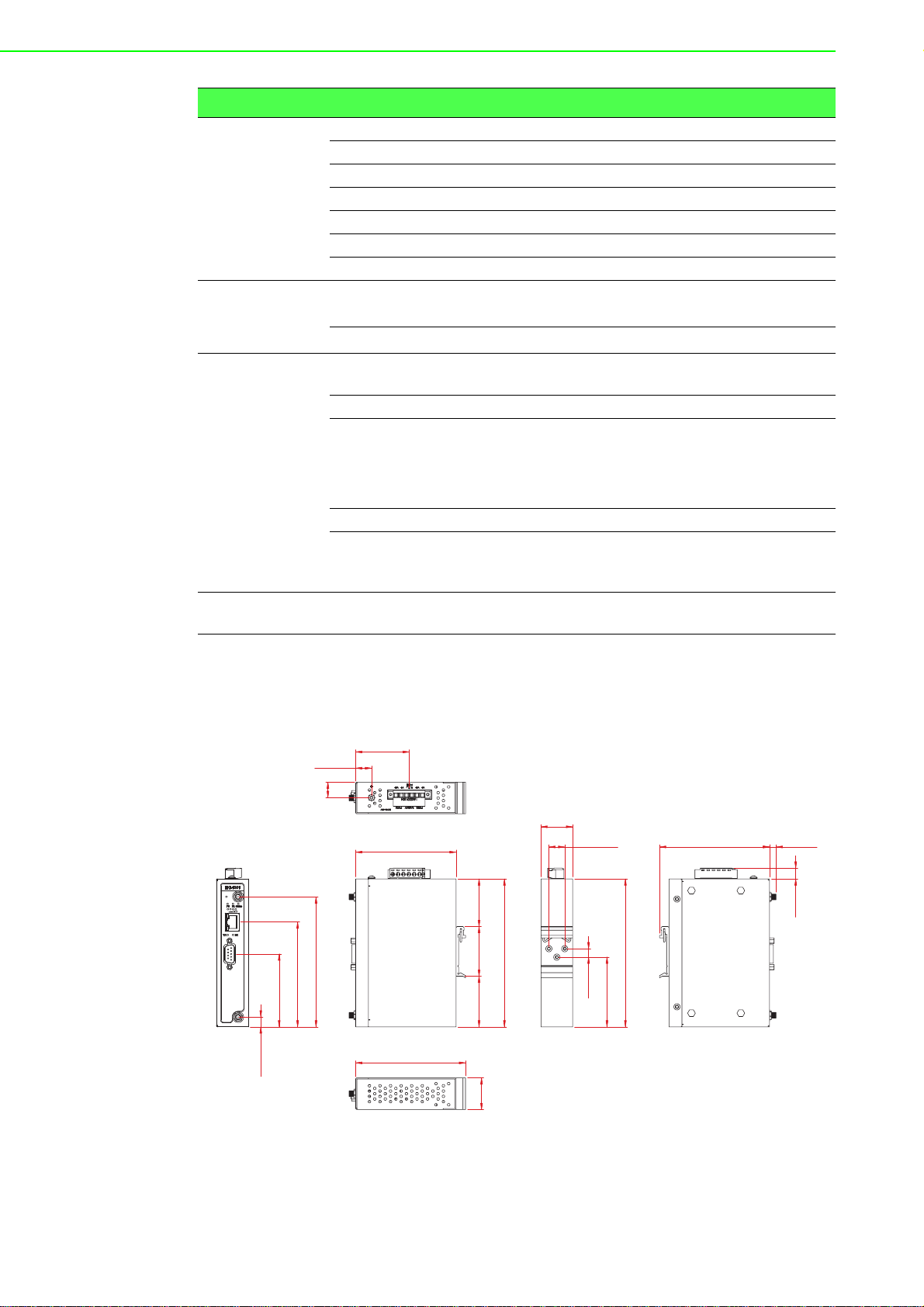
1.4 Dimensions
The following view depicts the EKI-1361.
50.70 [2.00]
15 [0.59]
14.53
[0.57]
30 [1.18]
95 [3.74]
123 [4.84]
99.20 [3.91]
69 [2.72]
104 [4.09]
9 [0.35]
140 [5.51]
48 [1.89] 47 [1.85] 45 [1.77]
30 [1.18]
15 [0.59]
140 [5.51]
8 [0.31]
66 [2.60]
Figure 1.1 EKI-1361 Dimensions
104 [4.09] 6.30 [0.25]
10.30 [0.41]
EKI-1360-BE Series User Manual 4
Page 16
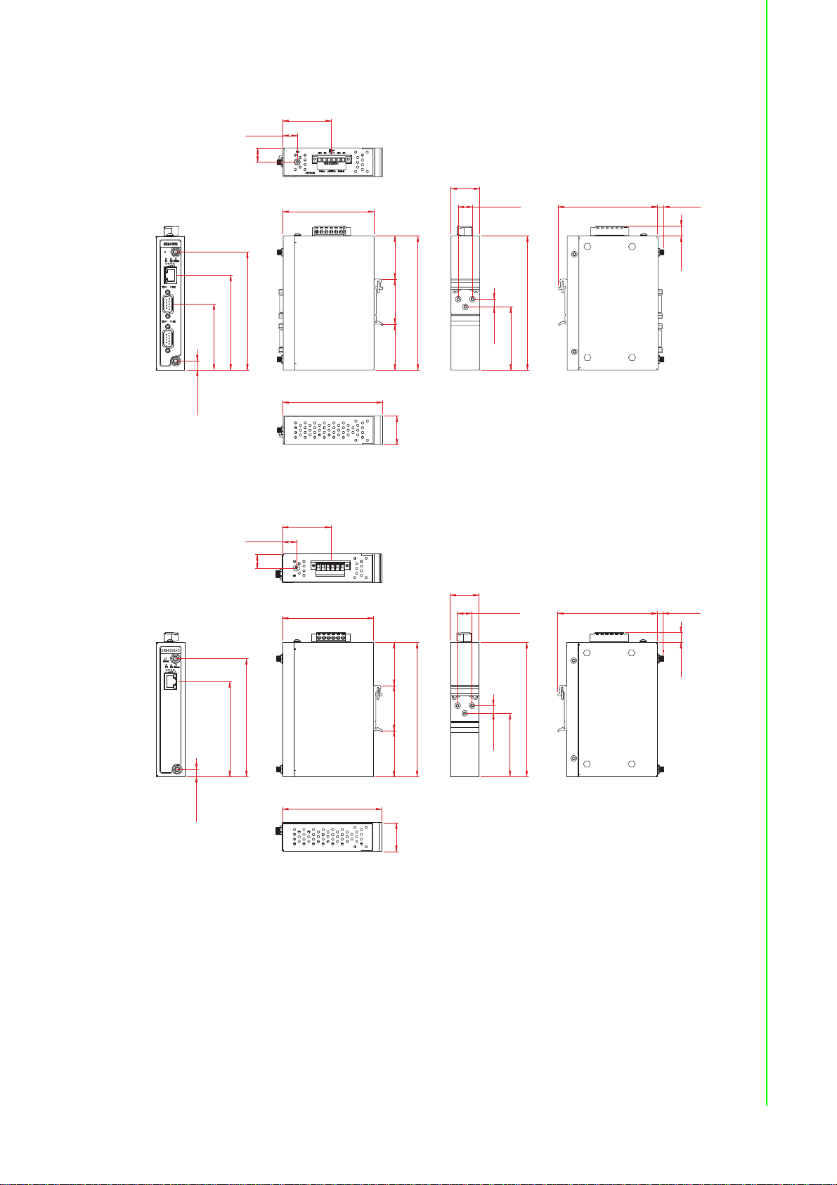
The following view depicts the EKI-1362.
Reset
WLAN
50.70 [2.00]
95 [3.74]
69 [2.72]
99.20 [3.91]
123 [4.84]
30 [1.18]
140 [5.51]
140 [5.51]
66 [2.60]
8 [0.31]
10.30 [0.41]
104 [4.09] 6.30 [0.25]
48 [1.89]
47 [1.85]
45 [1.77]
104 [4.09]
15 [0.59]
15 [0.59]
14.53
[0.57]
9 [0.35]
50.70 [2.00]
95 [3.74]
99.20 [3.91]
123 [4.84]
30 [1.18]
30 [1.18]
140 [5.51]
140 [5.51]
66 [2.60]
8 [0.31]
10.30 [0.41]
104 [4.09] 6.30 [0.25]
48 [1.89] 47 [1.85] 45 [1.77]
104 [4.09]
15 [0.59]
15 [0.59]
14.53
[0.57]
7.5 [0.30]
Figure 1.2 EKI-1362 Dimensions
The following view depicts the EKI-6333AC.
Figure 1.3 EKI-6333AC Dimensions
5 EKI-1360-BE Series User Manual
Page 17

Chapter 2
2Getting Started
Page 18
2.1 Hardware
EKI-1361
Reset
P1 P2 Status
WLAN
TX RX
1
3
4
1
2
5
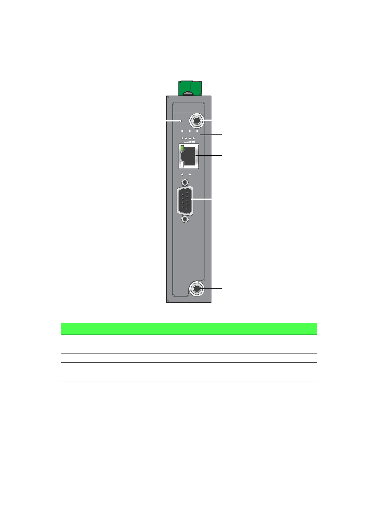
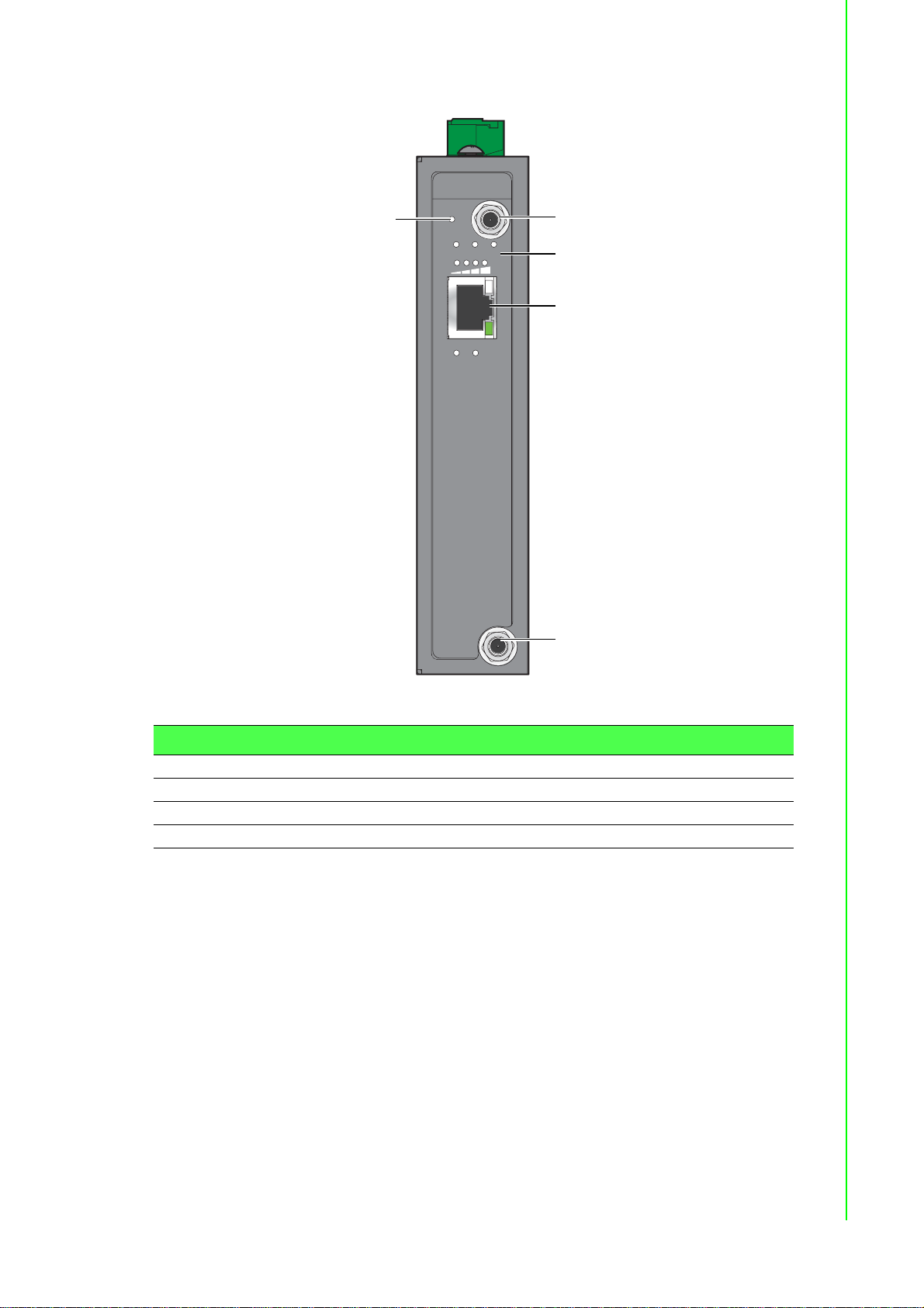
2.1.1 Front View
The following view shows the EKI-1361.
Figure 2.1 EKI-1361 Front View
No. Item Description
1 Antenna connector Connector for antenna.
2 System LED panel See “LED Indicators” on page 11 for further details.
3 ETH port RJ45 ports x 1.
4 Serial port DB9 pinout, supports RS-232/422/485.
5 Reset button Button allows for system soft reset or factory default reset.
7 EKI-1360-BE Series User Manual
Page 19
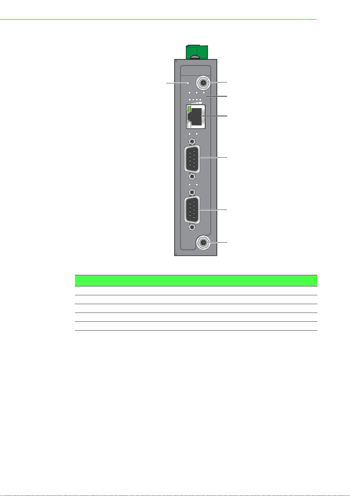
The following view shows the EKI-1362.
1
3
4
1
2
4
5
Reset
WLAN
TX RX
TX RX
EKI-1362
P1 P2 Status
Figure 2.2 EKI-1362 Front View
No. Item Description
1 Antenna connector Connector for antenna.
2 System LED panel See “LED Indicators” on page 11 for further details.
3 ETH port RJ45 ports x 1.
4 Serial port DB9 pinout, supports RS-232/422/485.
5 Reset button Button allows for system soft reset or factory default reset.
EKI-1360-BE Series User Manual 8
Page 20
The following view shows the EKI-6333AC.
EKI-6333AC
Reset
P1 P2 Status
TX RX
1
3
1
2
4
Figure 2.3 EKI-6333AC Front View
No. Item Description
1 Antenna connector Connector for antenna.
2 System LED panel See “LED Indicators” on page 11 for further details.
3 ETH port RJ45 ports x 1.
4 Reset button Button allows for system soft reset or factory default reset.
9 EKI-1360-BE Series User Manual
Page 21
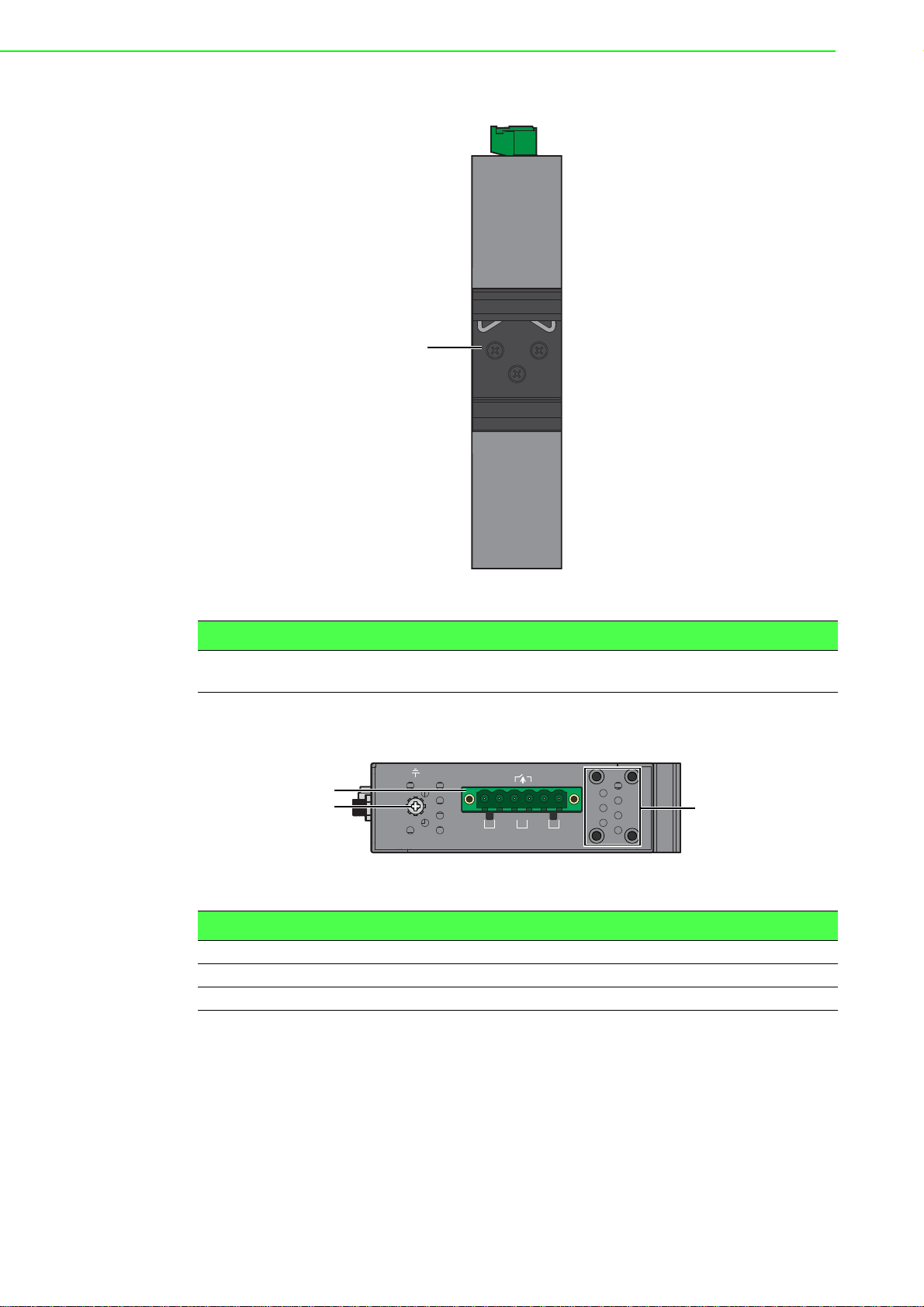
2.1.2 Rear View
1
PWR2
P-Fail
DC12-48V
PWR1
V2- V2+ V1- V1+
1A@24V
1
3
2
No. Item Description
1 DIN-Rail mounting
plate
2.1.3 Top View
No. Item Description
1 Terminal block Connect cabling for power and alarm wiring
2 Ground terminal Screw terminal used to ground chassis
3 Wall mounting holes Screw holes (x4) used in the installation of a wall mounting plate
Figure 2.4 Rear View
Mounting plate used for the installation to a standard DIN rail
Figure 2.5 Top View
EKI-1360-BE Series User Manual 10
Page 22

2.1.4 LED Indicators
Reset
P1 P2 Status
WLAN
1
2
3
4
5
Station Mode
No. LED Name LED Color Description
1 P1 Green Power 1 is on
2 WLAN Status Green WLAN link is ready
3 P2 Green Power 2 is on
4 Status Amber, blinking System is ready
5 WLAN Signal
Strength
Figure 2.6 System LED Panel
Off Power 1 is off or power error condition exists
Off WLAN is not functioning
Off Power 2 is off or power error condition exists
Off System is not functioning
Off No signal available
Green (One) Signal quality is less than -80 dBm
Green (Two) Signal quality is between -80 dBm and -60 dBm
Green (Three) Signal quality is more than -60 dBm
AP Mode
No. LED Name LED Color Description
1 P1 Green Power 1 is on
Off Power 1 is off or power error condition exists
2 WLAN Status On WiFi is connected
Off In AP mode, the LED is always off
3 P2 Green Power 2 is on
Off Power 2 is off or power error condition exists
4 Status Amber, blinking System is ready
Off System is not functioning
5 WLAN Signal
Strength
LED Name LED Color Description
Ethernet Green on 10Mbps Ethernet connection
Serial Amber Serial port is receiving data
Green Designates signal strength
Off WLAN is not functioning
Green, blinking Ethernet port is transmitting or receiving data
Amber 100Mbps Ethernet connection
Green 1000Mbps Ethernet connection
Green Serial port is transmitting data
Off No data is transmitted or received through the serial port
11 EKI-1360-BE Series User Manual
Page 23
2.2 Connecting Hardware
DIN rail clip
DIN rail
DIN rail clip
release tab
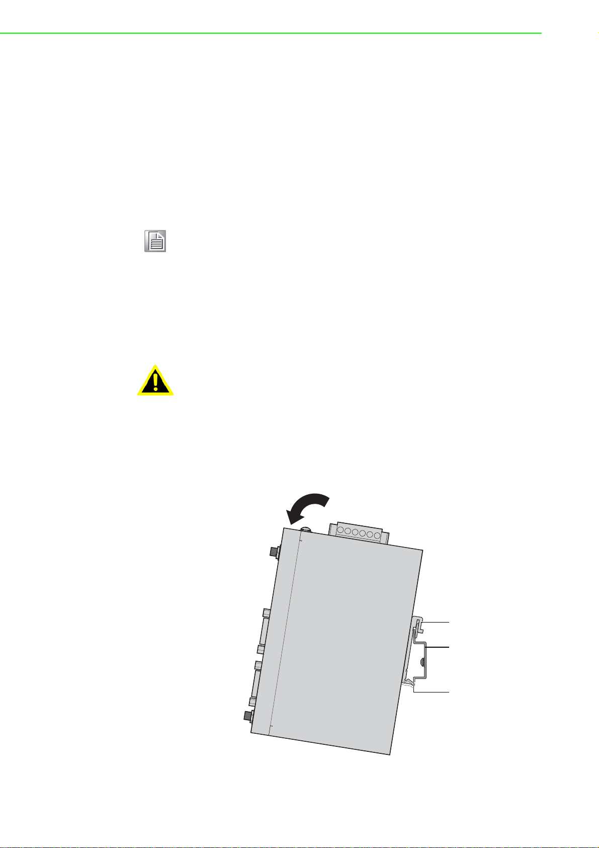
2.2.1 DIN Rail Mounting
The DIN rail mount option is the quickest installation option. Additionally, it optimizes
the use of rail space.
The metal DIN rail kit is secured to the rear of the switch. The device can be mounted
onto a standard 35 mm (1.37”) x 7.5 mm (0.3”) height DIN rail. The devices can be
mounted vertically or horizontally. Refer to the following guidelines for further
information.
Note! A corrosion-free mounting rail is advisable.
When installing, make sure to allow for enough space to properly install
the cabling.
2.2.1.1 Installing the DIN-Rail Mounting Kit
1. Position the rear panel of the switch directly in front of the DIN rail, making sure
that the top of the DIN rail clip hooks over the top of the DIN rail, as shown in the
following illustration.
Warning! Do not install the DIN rail under or in front of the spring mechanism on
the DIN rail clip to prevent damage to the DIN rail clip or the DIN rail.
Make sure the DIN rail is inserted behind the spring mechanism.
2. Once the DIN rail is seated correctly in the DIN rail clip, press the front of the
switch to rotate the switch down and into the release tab on the DIN rail clip.
If seated correctly, the bottom of the DIN rail should be fully inserted in the
release tab.
Figure 2.7 Installing the DIN-Rail Mounting Kit
EKI-1360-BE Series User Manual 12
Page 24
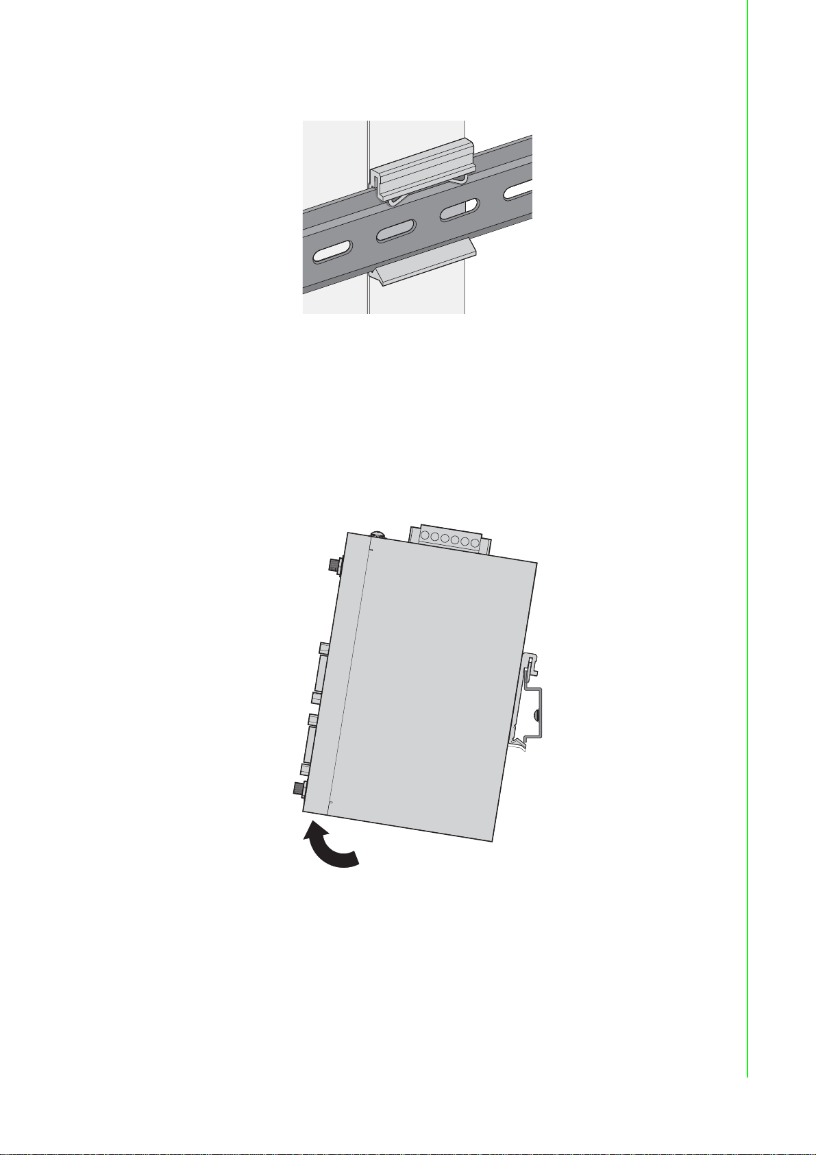
See the following figure for an illustration of a completed DIN installation
procedure.
Figure 2.8 Correctly Installed DIN Rail Kit
3. Grasp the bottom of the switch and slightly rotate it upwards. If there is
resistance, the switch is correctly installed. Otherwise, re-attempt the installation
process from the beginning.
2.2.1.2 Removing the DIN-Rail Mounting Kit
1. Ensure that power is removed from the switch, and disconnect all cables and
connectors from the front panel of the switch.
2. Push down on the top of the DIN rail clip release tab with your finger. As the clip
releases, lift the bottom of the switch, as shown in the following illustration.
\
Figure 2.9 Removing the DIN-Rail
13 EKI-1360-BE Series User Manual
Page 25
2.2.2 Wall-Mounting
The wall mounting option provides better shock and vibration resistance than the DIN
rail vertical mount.
Note! When installing, make sure to allow for enough space to properly install
the cabling.
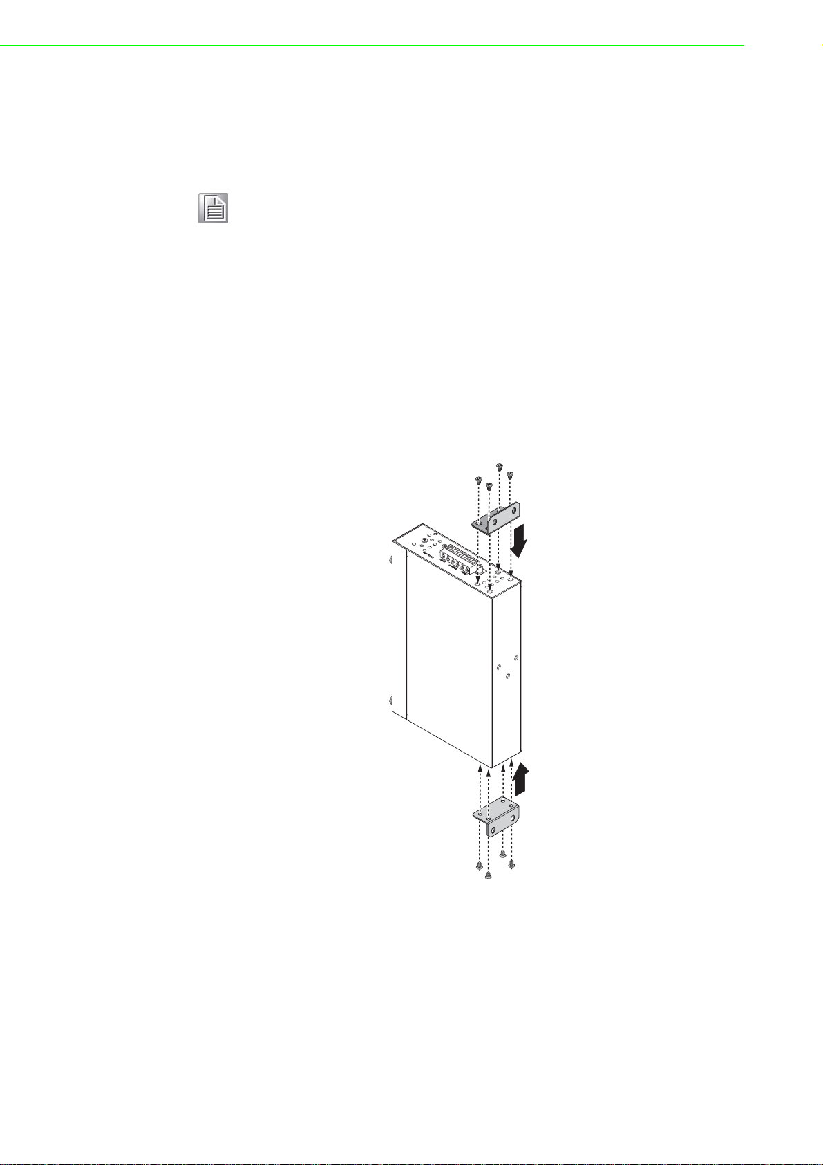
Before the device can be mounted on a wall, you will need to remove the DIN rail
plate.
1. Rotate the device to view the rear side and locate the DIN mounting plate.
2. Remove the screws securing the DIN mounting plate to the rear side.
3. Remove the DIN mounting plate. Store the DIN mounting plate and provided
screws for later use.
4. Align the wall mounting brackets with the designated location as illustrated in
the following figure. The screw holes on the device and the brackets align if
seated correctnly.
5. Secure the wall brackets to the device with M3 screws, see the following figure.
Figure 2.10 Installing Wall Mount Plates
Once the wall mounting brackets are secured on the device, mark the screw
hole location on the wall area.
6. On the installation site, place the device firmly against the wall. Make sure the
switch is vertically and horizontally level.
7. Insert a pencil or pen through the screw holes on the mounting bracket to mark
the location of the screw holes on the wall.
8. Remove the switch from the wall and drill holes over each marked location (4)
on the wall, keeping in mind that the holes must accommodate wall sinks in
addition to the screws.
EKI-1360-BE Series User Manual 14
Page 26
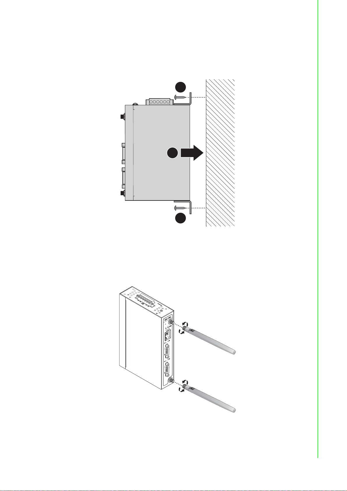
9. Insert the wall sinks into the walls.
2
2
1
R
e
set
WLA
N
10. Align the mounting bracket over the screw holes on the wall.
11. Starting with the upper bracket, insert a screw through the bracket and rotate it
to secure. Do not tighten at this point. Repeat for the remaining locations, see
the following figure.
Figure 2.11 Wall Mount Installation
12. Once the device is installed on the wall, tighten the screws to secure the device.
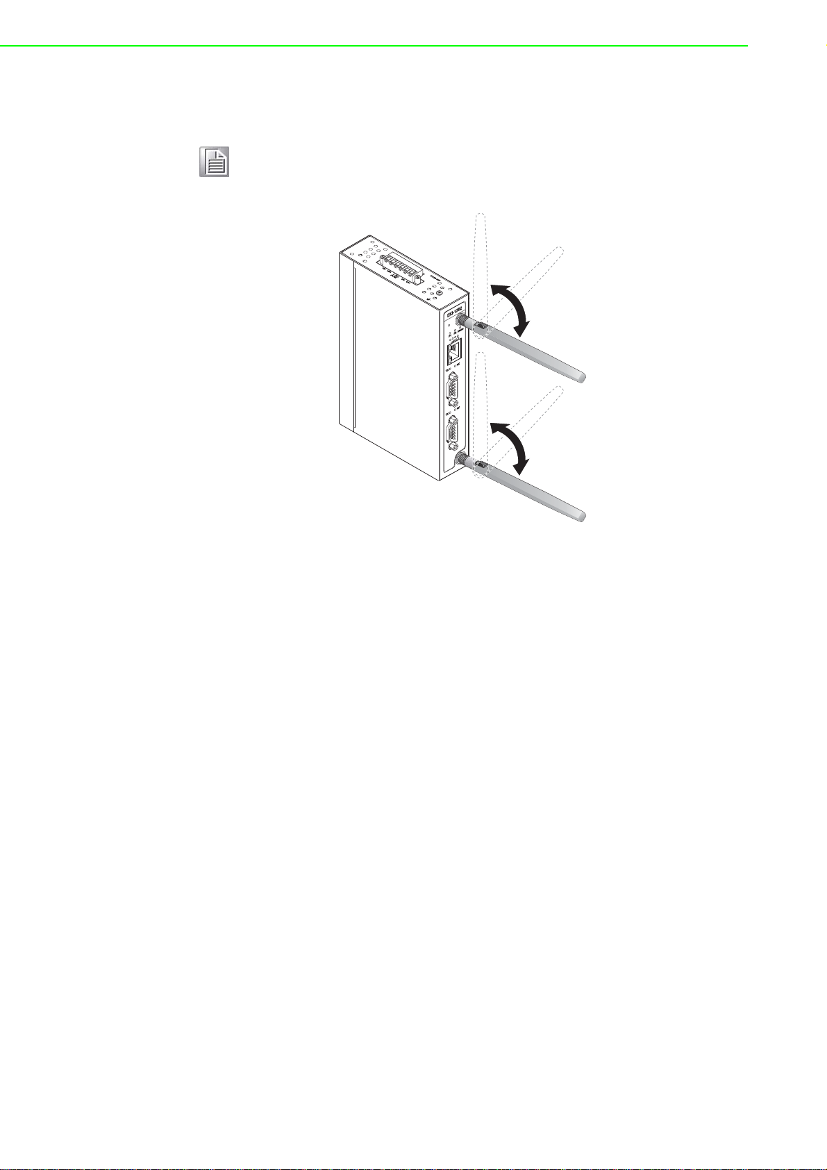
2.2.3 Wireless Connection
1. Connect the antenna by screwing the antenna connectors in a clockwise
direction.
Figure 2.12 Installing the Antenna
15 EKI-1360-BE Series User Manual
Page 27
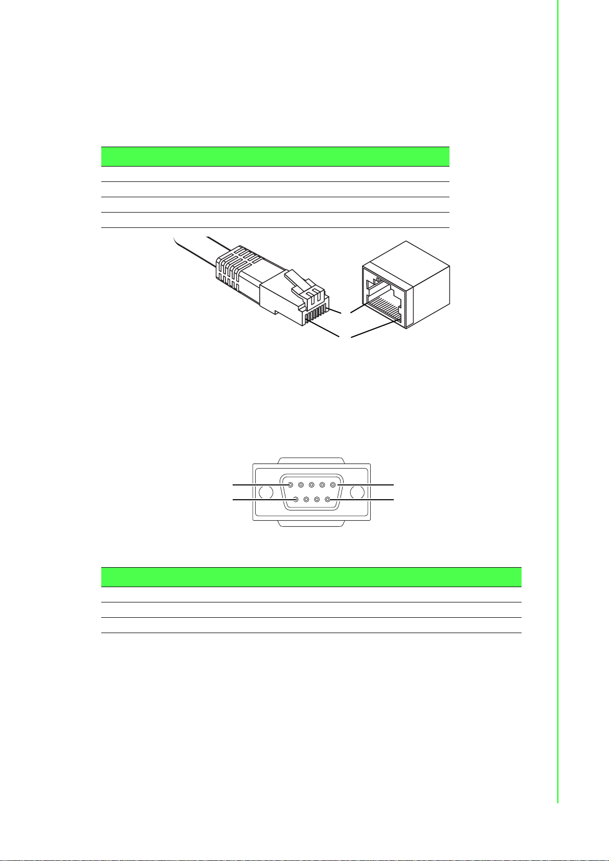
2. Position the antenna for optimal signal strength.
Re
set
WLA
N
Note! The location and position of the antenna is crucial for effective wireless
connectivity
Figure 2.13 Positioning the Antenna
EKI-1360-BE Series User Manual 16
Page 28
2.2.4 Network Connection
1
8
1
9
6
5
For RJ45 connectors, data-quality, twisted pair cabling (rated CAT5 or better) is
recommended. The connector bodies on the RJ45 Ethernet ports are metallic and
connected to the GND terminal. For best performance, use shielded cabling.
Shielded cabling may be used to provide further protection.
Straight-thru Cable Wiring Cross-over Cable Wiring
Pin 1 Pin 1 Pin 1 Pin 3
Pin 2 Pin 2 Pin 2 Pin 6
Pin 3 Pin 3 Pin 3 Pin 1
Pin 6 Pin 6 Pin 6 Pin 2
Figure 2.14 Ethernet Plug & Connector Pin Position
Maximum cable length: 100 meters (328 ft.) for 10/100BaseT.
2.2.5 Serial Connection
EKI-1360-BE Series provides up to four ports DB9 (male) connectors. RS-232/422/
485 pin assignments as below:
Pin 1 2 3 4 5 6 7 8 9
RS-232 DCD RX TX DTR GND DSR RTS CTS RI
RS-422 TX- TX+ GND RX+ RXRS-485 DATA- DATA+ GND
Figure 2.15 DB9 Pin Assignment
17 EKI-1360-BE Series User Manual
Page 29

2.2.6 Power Connection
s
Single DC Power Redundant DC Power
2.2.6.1 Overview
Warning! Power down and disconnect the power cord before servicing or wiring
the switch.
Caution! Do not disconnect modules or cabling unless the power is first switched
off.
The device only supports the voltage outlined in the type plate. Do not
use any other power components except those specifically designated
for the switch device.
Caution! Disconnect the power cord before installation or cable wiring.
The switches can be powered by using the same DC source used to power other
devices. A DC voltage range of 12 to 48 V
must be applied between the V1+
DC
terminal and the V1- terminal (PW1), see the following illustrations. The chassis
ground screw terminal should be tied to the panel or chassis ground. A redundant
power configuration is supported through a secondary power supply unit to reduce
network down time as a result of power loss.
EKI-1360-BE Series support 12 to 48 V
. Dual power inputs are supported and
DC
allow you to connect a backup power source.
P2 P1
Chassis
GND
(pane)
One DC Supply
P2 P1
Chassi
GND
(pane)
Dual DC Supplies
Figure 2.16 Power Wiring for EKI-1360-BE Series
EKI-1360-BE Series User Manual 18
Page 30
2.2.6.2 Considerations
Take into consideration the following guidelines before wiring the device:
The Terminal Block (CN1) is suitable for 12-24 A WG (3.31 - 0.205 mm
value 7 lb-in.
The cross sectional area of the earthing conductors shall be at least 3.31 mm
Calculate the maximum possible current for each power and common wire.
Make sure the power draw is within limits of local electrical code regulations.
For best practices, route wiring for power and devices on separate paths.
Do not bundle together wiring with similar electrical characteristics.
Make sure to separate input and output wiring.
Label all wiring and cabling to the various devices for more effective
management and servicing.
Note! Routing communications and power wiring through the same conduit
may cause signal interference. To avoid interference and signal
degradation, route power and communications wires through separate
conduits.
2.2.6.3 Grounding the Device
2
). Torque
2
.
Caution! Do not disconnect modules or cabling unless the power is first switched
off.
The device only supports the voltage outlined in the type plate. Do not
use any other power components except those specifically designated
for the switch device.
Caution! Before connecting the device properly ground the device. Lack of a
proper grounding setup may result in a safety risk and could be
hazardous.
Caution! Do not service equipment or cables during periods of lightning activity.
19 EKI-1360-BE Series User Manual
Page 31

Caution! Do not service any components unless qualified and authorized to do
Drain Wire with Lug
Connection to
Grounding Point
so.
Caution! Do not block air ventilation holes.
Electromagnetic Interference (EMI) affects the transmission performan ce of a device.
By properly grounding the device to earth ground through a drain wire, you can setup
the best possible noise immunity and emissions.
P-Fail
V2- V2+ V1- V1+
1A@24V
DC12-48V
PWR1
PWR2
By connecting the ground terminal by drain wire to earth ground the switch and
chassis can be ground.
Note! Before applying power to the grounded switch, it is advisable to use a
volt meter to ensure there is no voltage difference between the power
supply’s negative output terminal and the grounding point on the switch.
2.2.6.4 Wiring a Relay Contact
The following section details the wiring of the relay output. The terminal block on the
EKI-1360-BE Series is wired and then installed onto the terminal receptor located on
the EKI-1360-BE Series.
Figure 2.18 Terminal Receptor: Relay Contact
The terminal receptor includes a total of six pins: two for PWR1, two for PWR2 and
two for a fault circuit.
Figure 2.17 Grounding Connection
PWR2
V2- V2+ V1- V1+
1A@24V
P-Fail
PWR1
DC12-48V
EKI-1360-BE Series User Manual 20
Page 32

2.2.6.5 Wiring the Power Inputs
PWR2
P-Fail
DC12-48V
PWR1
V2- V2+ V1- V1+
1A@24V
Caution! Do not disconnect modules or cabling unless the power is first switched
off.
The device only supports the voltage outlined in the type plate. Do not
use any other power components except those specifically designated
for the switch device.
Warning! Power down and disconnect the power cord before servicing or wiring
the switch.
There are two power inputs for normal and redundant power configurations. The
power input 2 is used for wiring a redundant power configuration. See the following
for terminal block connector views.
Figure 2.19 Terminal Receptor: Power Input Contacts
To wire the power inputs:
Make sure the power is not connected to the switch or the power converter before
proceeding.
1. Loosen the screws securing terminal block to the terminal block receptor.
2. Remove the terminal block from the switch.
Figure 2.20 Removing a Terminal Block
3. Insert a small flat-bladed screwdriver in the V1+/V1- wire-clamp screws, and
loosen the screws.
4. Insert the negative/positive DC wires into the V+/V- terminals of PW1. If setting
up power redundancy, connect PW2 in the same manner.
21 EKI-1360-BE Series User Manual
Page 33

5. Tighten the wire-clamp screws to secure the DC wires in place.
Loosening
Wire-clamp
Screws
Installing
DC Wires
Securing
Wire-clamp
Screws
Figure 2.21 Installing DC Wires in a Terminal Block
6. Align the terminal block over the terminal block receptor on the switch.
7. Insert the terminal block and press it in until it is flush with the terminal block
receptor.
8. Tighten the screws on the terminal block to secure it to the terminal block
receptor.
If there is no gap between the terminal block and the terminal receptor, the
terminal block is seated correctly.
Figure 2.22 Securing a Terminal Block to a Receptor
2.3 Reset Button
Reset configuration to factory default:
Press and hold Reset button for 5 seconds.
System reboot:
Press and hold Reset button for 2 seconds.
EKI-1360-BE Series User Manual 22
Note! Do NOT power off the Ethernet switch when loading default settings.
Page 34

23 EKI-1360-BE Series User Manual
Page 35

Chapter 3
3Utility Configuration
Page 36

3.1 Installing the Configuration Utility
Note! Microsoft.NET Framework version 2.0 or greater is required for this
application.
1. Insert the Advantech EKI Device Configuration Utility CD-ROM into the CD-
ROM drive (whereas E:\ is the drive name of your CD-ROM) on the host PC.
2. Use Windows explorer or the Windows Run command to execute the setup
program, the path for the setup program on the CD-ROM is as follows:
E:\EKI_Device_Configuration_Utility_v2.01.exe
3. If there is an existing COM port mapping utility on the host PC, remove it at this
time. A system reboot may be necessary before continuing the installation.
4. Once the InstallShield Wizard screen displays, click Next to proceed with the
installation.
Figure 3.1 InstallShield Wizard 1 of 4
EKI-1360-BE Series User Manual 24
Page 37

5. The Software License Agreement displays, press I Agree to continue or Cancel
to stop the installation.
Figure 3.2 InstallShield Wizard 2 of 4
The InstallShield continues and a status screen displays. The default installation
path is C:\Program Files\EKI Device Configuration Utility.
Figure 3.3 InstallShield Wizard 3 of 4
25 EKI-1360-BE Series User Manual
Page 38

6. Once the installation of the package is finished a Configuration Utility Setup
screen displays. Click Finish to conclude the process and exit the InstallShield
Wizard.
Figure 3.4 InstallShield Wizard 4 of 4
EKI-1360-BE Series User Manual 26
Page 39

3.2 Starting the Configuration Utility
5
4
3
2
6
1
Advantech EKI-1360-BE Series device servers provide an easy-to-use utility to
configure your serial device server through an Ethernet connection. For secure
administration, it can also restrict the access rights for configuration to only one host
PC. With this secure function enabled, other PCs will not have permission for
configuration. After the installation program on the Advantech IEDG Series Driver
Utility CD-ROM is finished, the serial device servers are ready for use and
configuration.
Advantech Serial Device Server Configuration Utility is an excellent device server
management tool. You can connect and configure the local and remote Advantech
serial device servers easily. The utility provides access to the following functions:
Configure the network settings (you can set the IP address, Gateway address,
and Subnet mask)
Perform diagnostic tests (virtual COM port testing, port status list)
Perform administrative functions (export and import the serial device server
setting, manage access IP, a descriptive name, upgrade firmware)
You can open the Configuration Utility from the Windows Start Menu by clicking Start
> All Programs > EKI Device Configuration Utility > EKI Device Configuration
Utility. The Configuration Utility displays as shown in the following figure.
Figure 3.5 Configuration Utility Overview
No Item Description
1 Menu Bar Displays File, View, Management, Tools and Help.
2 Quick Tool Bar Useful management functions shortcuts.
3 Serial Device Server
List Area
4 Information Panel Click on the devices or move cursor to the devices, the related
5 Status Bar Displays the current time.
6 Configuration Area Click on the item on the Device Server List Area, the
Available devices are listed in this area. Devices and COM port s
can be organized or grouped in this area.
information is shown in this area.
configuration page displays.
27 EKI-1360-BE Series User Manual
Page 40

3.3 Discovering Your Device Server
3.3.1 Auto Searching
Advantech Serial Device Server Configuration Utility will automatically search all the
EKI-1360-BE Series device servers on the network and show them on the Serial
Device Server List Area of the utility. The utility provides an auto-search function to
show your device (s) by simply executing the configuration utility program from the
Start Menu.
From here all device on the same network domain will be searched and displayed on
Device Server List Area. You can click on the device name to show the features of
the specific device.
Click on the “+” before the model name, and the utility will expand the tree structure
to show the individual device name. Click on the “-” before the model name, and the
utility will collapse the tree structure.
Figure 3.6 Open View of Serial Device Configuration Utility
Note! When you run the configuration utility for the first time, the default device
name is obtained from the serial device’s MAC identification number.
The name can be altered through the configuration utility.
Select the device in this sub-tree. The first tab on the Configuration Area shows the
summary of “Basic Information” included device type, version, and name, “Ethernet
EKI-1360-BE Series User Manual 28
Page 41

Information”, and “Serial Port Information”. The serial port information frame displays
the operation mode, status and connected host IP.
Figure 3.7 Selecting a Group
Click on the “+” before the device name, and the utility will expand the interfaces on
this device server.
Figure 3.8 Selecting a Device
Click to enter the configuration page to change the setting. The configuration will be
introduced on following sections.
Figure 3.9 Viewing Basic Settings
29 EKI-1360-BE Series User Manual
Page 42

3.4 Network Settings
Prior to setting up the server’s IP address determine the IP address mode.
There are four mode types available:
Static IP: mode to assign a specific assigned address
DHCP / AutoIP: mode to automatically assign IP addresses through a DHCP
server
BOOTP / AutoIP: mode to automatically assign an IP address through the
configuration server
DHCP/BOOTP/AutoIP: mode to automatically assign an IP address using a
Bootstrap Protocol or DHCP server.
The server is set with the following default IP configuration:
10.0.0.1
The EKI-1360-BE Series includes a software utility option, which you can install on
your system, for configuration through computer-based software. The EKI-1360-BE
Series also includes a web interface option for configuration through a standard web
browser.
Figure 3.10 Utility Overview
EKI-1360-BE Series User Manual 30
Page 43

You can choose from four possible IP Configuration modes --- Static, DHCP, BOOTP,
and DHCP/BOOTP.
Figure 3.11 Network Settings Overview
Item Description
Sta tic IP Static IPUser defined IP address, Subnet Mask, and Default Gatewa y.
DHCP + Auto-IP DHCP Server assigned IP address, Subnet Mask, Default Gateway,
and DNS.
BOOTP + Auto-IP BOOTP Server assigned IP address.
DHCP + BOOTP +
Auto-IP
DNS Setting In order to use DNS feature, you need to set the IP address of the
DHCP Server assigned IP address, Subnet Mask, Default Gateway,
and DNS, or BOOTP Server assigned IP address. (If the DHCP
Server does not respond)
DNS server to be able to access the ho st with the domain name. The
EKI-1360-BE Series device server provides Primary DNS Server
and Secondary DNS Server configuration items to set the IP address
of the DNS server. Secondary DNS Server is included for use when
Primary DNS server is unavailable.
DHCP Advanced
Setting
When you enabling DHCP protocol to get IP address, it will be waited
DHCP server to give IP within DHCP time out. The default value is
180 seconds.
Note! When you have finished the configuration of these settings for each
category, please press the “Apply” button in order to make these
settings effective on the Serial Device Server.
31 EKI-1360-BE Series User Manual
Page 44

3.5 Administrator Settings
3.5.1 Locate the Serial Device Server
When several serial device servers are connected to the network, identification of a
specific serial device is possible through the Locate function.
To locate the serial device server:
1. From the device list frame, locate the desired device and right-click on it to
display the settings menu.
2. Select Locate from the menu.
Figure 3.12 Locate the Serial Device Server
The unit’s Status LED will turn solid amber and the buzzer will sound until you click
Stop Locate.
EKI-1360-BE Series User Manual 32
Page 45

3.5.2 Restore to Factory Default Settings
The configuration utility provides the function to restore the serial device server to
factory default settings.
Figure 3.13 Restore to Factory Default Settings
The confirm message will display after clicking Restore to Factory Default
Settings. If you really want to restore the serial device sever to factory default
settings, please click Yes button to continue.
Power off the serial device server within ten seconds. After reconnecting the power,
all settings will be reset to the factory default. If the power supply remains connected
for more than ten seconds, the serial device server will not be changed.
33 EKI-1360-BE Series User Manual
Page 46

3.5.3 Resetting the Device
The Reset Device is available to allow you to reset the serial device server. The
function disconnects both the ethernet and serial connections.
The function also allows the serial device server to save new configuration settings to
flash memory. Once a new setting is changed, you can use the Save function to
accept the changes. You will need to reset the device to save the settings to flash
memory .
To reset the device:
1. Right-click a desired device to display the settings menu.
2. Select Reset Device.
Figure 3.14 Reset Device
The device resets. Once the process is complete, the serial device server displays
under the Serial Device Server listing once again.
EKI-1360-BE Series User Manual 34
Page 47

3.5.4 Add to Favorite
The Add to Favorite function allows to easily map available devices to Favorite’s. By
bookmarking specific devices, you can create quickly accessible shortcuts for
existing critical devices from the vast pool of locally or remotely networked EKI-1360BE Series devices.
3.5.5 Auto Mapping
See “Auto Mapping” on page 45 for further details.
3.5.6 Manual Mapping
See “Manual Mapping” on page 47 for further details.
Figure 3.15 Add to Favorite
35 EKI-1360-BE Series User Manual
Page 48

3.5.7 Update Firmware
Advantech continually upgrades its firmware to keep up with the ever-expanding
world of computing. You can use the update firmware function in the utility to carry
out the upgrade procedure. Please access Advantech’s website: http://
www.advantech.com to download the latest version of the firmware. Before updating
the firmware, make sure that your host’s Network domain is as same as the serial
device server or the host can establish the TCP connection to the serial device
server.
To update firmware:
1. Right-click a desired device to display the settings menu.
2. Select Update Firmware.
Figure 3.16 Update Firmware
3. Select the firmware file you want to update.
Wait for a few seconds for the firmware to finish updating. After the update has
completed, click on the OK button. The serial device server will restart automatically.
Note! Be sure that the host PC Ethernet network domain is as same as the
EKI-1360-BE Series serial device server or the host PC can establish
the TCP connection with the serial device server while doing the
updating firmware process.
EKI-1360-BE Series User Manual 36
Page 49

Chapter 4
4Selecting An
Operating Mode
Page 50

4.1 Understanding the EKI-1360-BE Series
EKI 1360-BE Series
R
e
s
e
t
W
LA
N
Ethernet 1
Ethernet 1
PC
The EKI-1360-BE Series are wireless-based, serial device servers for connecting
RS-232/422/485 devices to a TCP/IP network. Once connected through EKI series,
the serial device will be able to send and receive data on a network like any other
network device. It extends traditional COM ports of a PC with access over a TCP/IP
network. Through networking, you can control and monitor remote serial devices
either over a LAN or over the WAN. Since the EKI series is connected through a
TCP/IP network, you might need to know some basic facts about networking in order
to get the server hooked up correctly.
4.1.1 Product Description
The EKI series is designed to network-enable any RS-232/422/485 serial device and
provide industry-grade hardware and easy-use software to make connecting serial
devices to an Ethernet network a surprisingly simple process. These units
immediately upgrade your existing serial devices for integration into the Internet
world. The EKI series features a lot of powerful functions such as: high speed data
transfer, access-control, auto-detection of all EKI series products, remote connection
from different network domain, remote firmware download, and more.
After the simple installation steps to attach your network and serial device to the
appropriate connectors on the serial device servers and driver installation, you will
then be able to communicate with the serial devices via its own application software
and with the EKI serial device server. COM port redirector, TCP server mode, TCP
client mode, UDP server mode, UDP client mode and Control mode are all different
schemes to make a serial connection across using one or more Serial device server.
Figure 4.1 Single Ethernet Connection
EKI-1360-BE Series User Manual 38
Page 51

4.1.2 COM Port Redirector
1
2
Ethernet 1
R
S232/422/485
Ethernet 2
EKI 1360-BE Series
R
e
se
t
W
L
A
N
RS232/422
4
22
EKI 1360-BE Series
PC
Advantech Serial Device Server Configuration Utility is a serial COM port redirector
that creates virtual COM ports and provides access to serial device connected to
Advantech serial device server. You can configure the serial device server and
enable the Virtual COM port using one integrated utility. Advantech Serial Device
Server Configuration Utility allows you to configure Microsoft applications to
communicate with network enabled serial device servers as easily as if they were
physically installed in or directly connected on the PC.
The Advantech redirector can create up to 4096 virtual COM ports. Application on the
host can open virtual COM port to access the serial device servers at the same time.
The redirector will handle each active virtual COM port as a separate TCP
connection to Advantech serial device servers.
4.1.2.1 Normal Mode
The Advantech redirector connects the Advantech serial device servers while an
Figure 4.2 COM Port Redirector
application open the COM port and disconnects from the Advantech serial device
servers when the application closes the COM port. The redirector uses TCP network
connections to the Advantech serial device server to gain the access to the
connected serial devices.
39 EKI-1360-BE Series User Manual
Page 52

4.1.2.2 Multi-Access Mode (Shared COM port mode)
1
2
Ethernet 1
RS232/422/485
EKI 1360-BE Series
PC
RS232/422/485
/4
EKI 1360-BE Series
PC
PC
Most of serial devices are connected directly and physically to the PC serial ports via
a cable. The operation system, ex. Windows XP, provides the COM ports that user’s
application can access, and control the serial device through the serial cable. This
means that the serial device can be connected to one host and only one application
on this host can handle input, output and control operation on this device.
If you want to run more than one applications to use a serial device, you can employ
EKI serial device servers that provide a virtual COM port for a host or multi-hosts on
an Ethernet network. EKI serial device server is located between hosts and serial
devices. Each serial port on the EKI serial device server can allow max. five host
connections through one Ethernet port or two Ethernet ports. There are two major
operation modes for Multi-Access Mode. First one is broadcast mode; EKI serial
device server handles a command from one application and replies the data from the
serial port to all applications that are connecting this serial port. Another one is polling
mode; EKI serial device server handles the command from one application and reply
to this application only. Query from other applications must be queued and wait for
current process completing.
Figure 4.3 Multi-Access Mode
By using a serial device server to share serial device, you eliminate the separate
serial lines and serial devices that can be attached to individual hosts. Collecting the
data from these serial devices become more easily and more effectively.
EKI-1360-BE Series User Manual 40
Page 53

4.1.3 TCP Server Mode
R
e
se
t
W
L
A
N
In TCP server mode, you might initiate the TCP connection from host to EKI serial
device server. This operation mode support max. Five simultaneous connections for
each serial port on EKI serial device server from one host or several hosts, however
multi-hosts collect the data from one serial port at the same time.
EKI 1360-BE Series
RS232/422/485
PC
Ethernet 1
Ethernet 2
1
2
Establish
the connection from
host
Figure 4.4 TCP Server Mode
41 EKI-1360-BE Series User Manual
Page 54

4.1.4 TCP Client Mode
1
2
Ethernet 1
RS232/422/485
EKI 1360-BE Series
R
e
se
t
W
L
A
N
PC
Establish
the connection from
serial device server
In TCP Client mode, the TCP connection will be established from EKI serial device
server . This operation mode su pports a maximum o f 16 simult aneous connections for
each serial port on EKI series to one host or several hosts. You should configure the
IP address and TCP port number of the network hosts which the EKI serial device
server connect to using Advantech Serial Device Server Configuration Utility. After
configuration, when EKI serial device server receives the data from serial port, the
device server will employ the connection to hosts which are configured.
Figure 4.5 TCP Client Mode
EKI-1360-BE Series User Manual 42
Page 55

4.1.5 Serial Tunneling Mode
R
e
s
e
t
W
L
A
N
R
es
e
t
W
L
A
N
Two native serial devices can communicate over an Ethernet network without any
intermediate host PC and software programming. Serial Tunneling is very simple to
use. You can use Advantech Serial Device Server Configuration Utility to designate
one serial port as the tunneling master and another serial device server port as the
tunneling slave.
EKI 1360-BE Series
RS232/422/485
Ethernet 1
EKI 1360-BE Series
RS232/422/485
1
2
Figure 4.6 Serial Tunneling Mode
4.1.6 UDP Server/Client Mode
UDP is used primarily for broadcasting messages over a network. In the UDP server
mode, EKI series access max. 8 hosts’ UDP message. In the UDP client mode, EKI
serial device servers transmit UDP message to max. 16 hosts simultaneously.
4.1.7 Control Mode
In controlling mode, the EKI serial device server presents a modem interface to the
attached serial device: it accepts AT-style modem commands to connect / disconnect
to other networking device. If you want serial device running application program to
connect/disconnect to different devices by request, you can use controlling mode.
The controlling mode provides three kinds of modem AT-style commands. The serial
devices can use these commands to control EKI series connecting or disconnecting
to remote networking devices. Thus intelligent serial devices such as stand-alone
PLC will send /receive data to/from devices one by one via Ethernet.
43 EKI-1360-BE Series User Manual
Page 56

Chapter 5
5Setting up Virtual COM
Port
Page 57

5.1 Setting COM Port Redirector
Advantech COM port mapping software is a serial COM port redirector that creates
virtual COM ports and provides access to serial devices connected to an Advantech
serial device servers. Your serial device applications can communicate with serial
devices connected to the Advantech serial device servers without sof tware chan ges.
Since the virtual COM ports work like standard Windows COM ports, your application
software sees no difference between a local serial device and one connected to an
Advantech serial device server.
The COM redirector utility and the virtual COM port management utility are integrated
into one utility with same GUI. The Advantech Serial Device Server Configuration
Utility can create all Virtual COM ports using the Auto Mapping function or by using
the manual mapping function.
5.2 Virtual COM Port Mapping
5.2.1 Auto Mapping
1. On your desktop, navigate to Start > All Programs > EKI Device
Configuration Utility and click Advantech EKI Device Configuration Utility
to open the utility.
2. Under Serial Device Servers, locate your server and click the icon to expand
the listing.
3. Select the target device and right-click on it to open up the options menu
window.
4. Locate Auto Mapping and select it.
Figure 5.1 Selecting Auto Mapping
The Batch Automatic Mapping Virtual COM Port window displays.
45 EKI-1360-BE Series User Manual
Page 58

5. Locate From System Port and click the drop-down menu to select the target
System Port
Device PortSelected Options
COM port.
6. From the network address list, select the address options to map.
The selected address displays the Device Port and (EKI-1360-BE Series device
server physical serial port) and the system port which will be the VCOM port for
the PC.
Figure 5.2 Selecting Auto Mapping
7. From the network address list, select the address options to map.
8. Click Map Selected Ports to set the configuration.
Figure 5.3 Mapping Selected Ports
Once the mapping function is initialized, a successful mapping process results in the
virtual mapping of the designated physical serial port and VCOM PC port. See the
following figure.
Figure 5.4 Viewing VCOM Mapping Results
EKI-1360-BE Series User Manual 46
Page 59

5.2.2 Manual Mapping
VCOM PC Port
EKI Physical
Serial Port
1. On your desktop, navigate to Start > All Programs > EKI Device
Configuration Utility and click Advantech EKI Device Configuration Utility
to open the utility.
2. Under Serial Device Servers, locate your server and click the icon to expand
the listing.
3. Select the target device and right-click on it to open up the options menu
window.
4. Locate Manual Mapping and select it.
Figure 5.5 Selecting Manual Mapping
The Manual Mapping Virtual COM Port window displays.
5. In the Device > Serial Port drop-down menu, select the target port to map.
This is the physical serial port on the EKI-1360-BE Series device.
6. In the Host > COM Port drop-down menu, select the target COM port to map.
This is the virtual port on the target PC.
Figure 5.6 Viewing Manual VCOM Mapping Results
47 EKI-1360-BE Series User Manual
Page 60

7. Click Map it to continue the process. The mapping process may require a short
time. Once this step is completed, the Manual Mapping Virtual COM Port
window displays again to map the VCOM port on the target PC.
Once the mapping function is initialized, a successful mapping process results
in the virtual mapping of the designated physical serial port and VCOM PC port.
See the following figure.
Figure 5.7 Viewing Manual VCOM Mapping Results
To allow for an automatic connection after a reboot or a power up, click the Auto
Reconnect option to enable this function.
5.2.3 Configuration Wizard
1. On your desktop, navigate to Start > All Programs > EKI Device
Configuration Utility and click Advantech EKI Device Configuration Utility
to open the utility.
2. Under Serial Device Servers, locate your server and click the icon to expand
the listing.
3. From the tool bar, select Configuration Wizard.
Figure 5.8 Selecting the Configuration Wizard
The Wizard screen displays and lists available devices.
4. Select the target device and click Next to continue.
The Wizard Device Settings window displays.
5. Under Serial Port Settings, click the Type drop-down menu and select the port
type.
Review the settings under the Ethernet fields and verify them.
6. Click Next to continue or Previous to return to the previous screen.
The selected settings are displayed in the following Wizard window.
7. Locate the radio button correlating to the target port to modify and click on it to
select it.
Verify the Device Port (EKI-1360-BE Series device physical serial port) and
System Port (virtual COM port for PC) settings before continuing.
8. Click Finish to complete the process. A Wizard complete! screen displays
indicating the completion of a successful procedure.
EKI-1360-BE Series User Manual 48
Page 61

5.2.4 Confirming Virtual COM Settings
1. On your desktop, navigate to Start > All Programs > EKI Device
Configuration Utility and click Advantech EKI Device Configuration Utility
to open the utility.
2. Locate Serial Ports menu in the menu pane and click on the Expand icon next
to Virtual COM Ports to view a list of the mapped ports.
3. Select a VCOM port to view its settings.
Figure 5.9 Serial Port Listing on EKI-1360-BE Series Device
For the next step, you will need to open the device manager on your system.
Using the Device Manager, you can both view and change the COM port
settings.
Note! The following instructions were developed in a Windows 7 environment;
the Windows XP equivalent is displayed in parentheses (). Instructions
may vary according to the operating system used.
4. On your desktop, click on the Start button and then on Control Panel. A
window displays showing all the available control panels.
5. Click on Hardware and Sound (Hardware). A list of all available hardware
configuration options displays.
6. Under Devices and Printers, click on the Device Manager link. A new window
displays showing a list of all the available devices on your computer.
7. Locate Ports (COM & LPT) and click on the expand icon. A list of all available
serial and parallel port devices display.
49 EKI-1360-BE Series User Manual
Page 62

The newly mapped VCOM port should be listed under the same mapped
settings used in the previous steps.
Figure 5.10 System Port VCOM Mapping Configuration
The newly mapped VCOM port is listed under the same mapped settings used
in the previous steps. The settings correspond to the VCOM port configuration
on the EKI-1360-BE Series device, see the following figure.
Figure 5.11 Verifying VCOM Mapping Configuration
If the settings do not correspond, the VCOM mapping is not correct. See “Virtual
COM Port Mapping” on page 45 to re-map the VCOM ports.
EKI-1360-BE Series User Manual 50
Page 63

5.2.5 Removing VCOM Ports
1. On your desktop, navigate to Start > All Programs > EKI Device
Configuration Utility and click Advantech EKI Device Configuration Utility
to open the utility.
2. Under Serial Ports, click the expand icon on Virtual COM Ports to view the
configured port list.
3. Locate the port to remove and right-click on it to open the options menu.
4. Scroll down to Remove This Port and click on it to initiate the procedure.
Figure 5.12 Remove VCOM Port
A Remove Port confirmation window displays.
5. Click OK to continue with the removal process or Cancel to return to the
previous menu.
Once the procedure is completed, a prompt displays the successful removal of
the port from the VCOM mapping list.
51 EKI-1360-BE Series User Manual
Page 64

5.2.6 Exporting and Importing VCOM Mapping
Importing and exporting Virtual COM Port Mapping is useful when the factory has
already used a number of serial device servers in VCOM mode. You can easily
upgrade to a new utility, and don’t need to re-map the Virtual COM Ports. For
example, when you would like to upgrade from Utility 1.71 to Utility 3.0, you can
export your own mapped Virtual COM Ports in Utility 1.71 and save them as a *.cpm
file.
After upgrading to Utility 3.0, import your *.cpm file and restore your own V irtual COM
Ports.
Note! This Virtual COM Port Mapping tool can only recover Virtual COM Ports
that have been mapped previously. For newly installed serial device
servers, please follow the virtual COM Port mapping steps.
1. On your desktop, navigate to Start > All Programs > EKI Device
Configuration Utility and click Advantech EKI Device Configuration Utility
to open the utility.
2. Locate Serial Ports menu in the menu pane and click on the Expand icon next
to Virtual COM Ports to view a list of the mapped ports.
3. Select a VCOM port.
4. Click Import V irtual COM Port Mapping or Export Virtual COM Port Mapping
in the File menu.
EKI-1360-BE Series User Manual 52
Page 65

Chapter 6
6Web Interface
Page 66

6.1 Overview
EKI-1360-BE Series serial device server can be configured through a web interface.
By using a standard web browser, the same procedure as with the Windows
configuration utility can be used. In the browser’s address field, enter the IP Address
of your EKI-1360-BE Series serial device server. The default IP setting is 10.0.0.1,
but you should use the IP which you have previously assigned for this device. Once
the IP is entered, you will be presented with the following windows.
Note! Before using the web-based configuration, make sure your host PC
Ethernet network IP domain is as same as the serial device server, or it
can establish the TCP connection with the serial device server.
Note! It is recommended that you use Microsoft Internet Explorer 7.0 or
higher.
6.2 Accessing the Web Page
6.2.1 Accessing the Web Page via Configuration Utility
To access the web page via configuration utility:
1. Select Ethernet under the desired device.
2. Click Launch Browser.
Figure 6.1 Accessing the Web Page via Configuration Utility
EKI-1360-BE Series User Manual 54
Page 67

6.2.2 Accessing the Web Page via Web Browser
Once the device is installed and connected, power on the device. The following
information guides you through the logging in process.
1. Launch your web browser on the PC.
2. In the browser’s address bar, type the device’s default IP address (LAN
Interface 1: 10.0.0.1).
The main menu is shown.
6.3 Overview
To access this page, click System.
Figure 6.2 System
The following table describes the items in the previous figure.
Item Description
System Info
Firmware Version Display the current firmware version of the device.
Local Hostname Display the current local hostname of the device.
System Time Displays the current date of the device.
System Up Time Displays the time since the last device reboot.
System Platform Displays the model name of the device.
Memory
Total Available Displays the total amount of physical memory installed RAM in
kiloBytes (kB) on the device.
Free Displays the currently unused RAM in kiloBytes (kB) on the device.
Buffered Displays the RAM in kiloBytes (kB) set aside as a temporary
holding place for data.
55 EKI-1360-BE Series User Manual
Page 68

Item Description
Local Network
Local IP Address Displays the assigned IP address of the device.
Local Netmask Displays the assigned netmask of the device.
MAC Address Displays the MAC address of the device.
6.4 Network Settings
6.4.1 LAN
To access this page, click Network Settings > LAN.
Figure 6.3 Network Settings > LAN
The following table describes the items in the previous figure.
Item Description
Local Hostname Enter the device name: up to 31 alphanumeric characters.
Network mode Click the drop-down menu to select the IP Address Setting mode:
Static or DHCP.
IP Address Enter a value to specify the IP address of the interface. The default
is 10.0.0.1.
Subnet Mask Enter a value to specify the IP subnet mask for the interface. The
default is 255.255.255.0.
Default Gateway Enter a value to specify the default gateway for the interface. The
default is 192.168.1.254.
DNS Click the radio button to select the DNS mode: Automatic or
Specific.
DNS 1 Enter a value to specify the default DNS 1 for the interface. The
default is 192.168.1.1.
DNS 2 Enter a value to specify the default DNS 2 for the interface.
MAC Address Display the MAC address to which packets are statically
forwarded.
Apply Click Apply to save the values and update the screen.
EKI-1360-BE Series User Manual 56
Page 69

Note! All new configurations will take effect after rebooting. To reboot the
device, click Administration > Tools > Reboot.
6.5 Wireless Settings
6.5.1 Basic
To access this page, click Wireless Settings > Basic.
Figure 6.4 Wireless Settings > Basic
The following table describes the items in the previous figure.
Item Description
Wireless Network
Operation Mode Click the drop-down menu to select an operation mode.
SSID Enter the name to distinguish it from other networks in your
neighborhood.
SSID broadcast Click the drop-down menu to enable or disable the SSID broadcast
function. The function is only enabled when Operation Mode is set
to Access Point.
AP Isolation Click the drop-down menu to enable or disable the AP Isola tio n
function.The function is only enabled when Operation Mode is set
to Access Point.
57 EKI-1360-BE Series User Manual
Page 70

Item Description
BSSID Display the MAC address of the device.
Operation frequency
Country Code Click the drop-down menu to select the country code to specify
different selectable channels. Available options: US (United
States), Germany, France, China and Japan. Some specific
channels and/or operational frequency bands are country
dependent.
Channel Selection Click the drop-down menu to select Auto (default) or Manual. The
Auto selection allows the device to select a band. The Manual
selection provides access to a selection of the option band (2.4G /
5G).
Band Click the drop-down menu to select the band channel. The function
is only enabled when Channel Selection is set to Manual.
Channel bandwidth
or
Band / Channel
bandwidth
Channel / Frequency Select the 2.4 or 5G wireless frequency to the least congested
Apply Click Apply to save the values and update the screen.
Click the drop-down menu to select the band and channel
bandwidth.
channel. The available settings on a 2.4G setting ar e 2.412 GHz to
2.462 GHz. For 5G, the available settings are 5.18 GHz to
5.825 GHz.
6.5.2 Advanced
To access this page, click Wireless Settings > Advanced.
The following table describes the items in the previous figure.
Item Description
Client Settings
Roam Click the drop-down menu to enable/disable the roaming function
Figure 6.5 Wireless Settings > Advanced
(default: Disable). The function allows client devices to switch
between one access point (AP) to another.
EKI-1360-BE Series User Manual 58
Page 71

Item Description
Watchdog The function stops unsecured wireless LAN usage across the
network.
Disassociation: Transmits disassociation and de-
authentication frames to prevent client association. Detected
rogue WLANs.
Ping: The feature pings a specified IP address. If there is no
response to the pings, the AP performs one of the following
functions: Restart WiFi, Reboot, or Force Re-association.
Watchdog Action Click the drop-down menu to associate a response to the
Watchdog event, options: Restart WiFi, Reboot, Force Reassociation.
Disassociate Timer Set the timer in seconds to set the disassociation setting. If the
device stays in an invalid state for as long as the set timer period,
the system automatically reboots.
Ping target Enter the IP address to ping when Watchdog Ping is selected.
Ping Waittime Enter a value in seconds to designate the interval between pings.
Ping Loss Counter Enter a value to activate the Watchdog function when the
configuraed number of ping failure time is reached.
Advanced Wireless Setting
Transmission Power Click the drop-down menu to set the transmission power of the
WiFi. By default the AP transmits at full power: Full, Half, Quarter.
Short Guard Interval Click the drop-down menu to enable/disable the short guard
interval. In 802.11 operation, the guard interval is 800ns. The short
guard interval time is 400ns to allow for an increased throughput.
Apply Click Apply to save the values and update the screen.
6.5.3 Security
To access this page, click Wireless Settings > Security.
The following table describes the items in the previous figure.
Item Description
Security Policy
Security Mode Click the drop-down menu to select the encryption when
Apply Click Apply to save the values and update the screen.
Figure 6.6 Wireless Settings > Security
communication. Available options: None, WEP, WPA-Personal and
WPA-Enterprise. If data encryption is enabled, the key is required
and only sharing the same key with other wireless devices can the
communication be established.
59 EKI-1360-BE Series User Manual
Page 72

6.5.4 Statistics
To access this page, click Wireless Settings > Statistics.
Figure 6.7 Wireless Settings > Statistics
The following table describes the items in the previous figure.
Item Description
Overview
Mode Display the current operation mode of the device.
SSID Display the SSID.
Channel / Frequency Display the current channel / frequency of the device.
Receive Stat istics
BSSID Displays the basic service set identifier (BSSID), access point
unique MAC address.
Signal Level Displays the power level measure in decibel-milliwatts of the listed
BSSID.
Wlan status
TX packets Display the current Tx packets.
TX bytes Display the current Tx bytes.
RX packets Display the current Rx packets.
RX bytes Display the current Rx bytes.
Apply Click Apply to save the values and update the screen.
EKI-1360-BE Series User Manual 60
Page 73

6.5.5 Site Survey
To access this page, click Wireless Settings > Site Survey.
Figure 6.8 Wireless Settings > Site Survey
The following table describes the items in the previous figure.
Item Description
Refresh Click Refresh to update the screen.
61 EKI-1360-BE Series User Manual
Page 74

6.5.6 Access Control
The Access Control feature is only available when the wireless mode of the device is
set to AP, see “Basic” on page 57.
Access Control allows for an administrator to allow or deny access by defining
specific devices through their MAC address.
To access this page, click Wireless Settings > Access Control.
Figure 6.9 Wireless Settings > Access Control
The following table describes the items in the previous figure.
Item Description
Access Control Method Click the drop-down menu to set the access control method:
Apply Click Apply to save the values and update the screen.
Disable, Deny or Allow.
In the Deny or Allow menu, enter the MAC address of the target
device - support for up to 32 target devices.
EKI-1360-BE Series User Manual 62
Page 75

6.5.7 Log
To access this page, click Wireless Settings > Log.
Figure 6.10 Wireless Settings > Log
The following table describes the items in the previous figure.
Item Description
Download Click Download to download the log file.
63 EKI-1360-BE Series User Manual
Page 76

6.6 Port Configuration
The serial port configuration menu has Basic, Operation Mode, and Advanced
Settings.
6.6.1 Basic
The Basic menu allows for the configuration of the serial interface type, baud rate,
parity, data / stop bits, and flow control for port configuration.
To access this page, click Port Configuration > Basic.
Figure 6.11 Port Configuration > Basic
The following table describes the items in the previous figure.
Item Description
Type Click the drop-down menu to select a serial interface: RS232,
RS422 or RS485.
Baud Rate Enter a value to specify the baud rate. The value should conform
to the current transmission speeds of connected devices when
setting the baud rate.
Parity Click the drop-down menu to select the parity: None, Odd, Even,
Mark or Space.
Data Bits Click the drop-down menu to select the data bits: 5, 6, 7, or 8.
Stop Bits Click the drop-down menu to select the stop bits: 1, 1.5 or 2.
Flow Control Click the drop-down menu to select the flow control mode: None,
Xon/Xoff or RTS/CTS
Apply Click Apply to save the values and update the screen.
EKI-1360-BE Series User Manual 64
Page 77

6.6.2 Operation
The Operation menu allows for the configuration of the mode type and related
attributes for port configuration.
To access this page, click Port Configuration > Operation.
Figure 6.12 Port Configuration > Operation
The following table describes the items in the previous figure.
Item Description
Mode Click the drop-down menu to select the port configuration mode:
Virtual COM Mode, USDG Data Mode, USDG Control Mode or
RFC2217 Mode.
Host Idle Timeout(s) Enter a value to define the host idle timeout period.
Response Timeout(s) Enter a value to define the response timeout period.
Frame Break(ms) Enter a value to specify the frame break time.
Pack conditions (Pack sent immediately when reach 1024 Bytes)
By size Click the option to sent pack immediately by size.
By interval Click the op tio n to sent pack immediate ly by interval.
By end-character Click the option to sent pack immediately by end-character.
Port Data Buffering
Media Click the drop-down menu to select port data buffering type: None
or RAM.
65 EKI-1360-BE Series User Manual
Page 78

Item Description
When Data Full Click the drop-down menu to select process mode when data full:
Apply Click Apply to save the values and update the screen.
6.6.3 Advanced
The Advanced menu allows for the configuration of the time delay, buffer data size
and FIFO size for port configuration.
To access this page, click Port Configuration > Advanced.
Stop.
Figure 6.13 Port Configuration > Operation
The following table describes the items in the previous figure.
Item Description
Ignore Purge Click the option to purge the serial port when the serial port opens
first time.
Disable Character
Timeout Detection
Disable Multiple
Connection
Enable BufferData Size Click the option to enter the value to queue data to become a
USDG Advanced Options (Flow Control will overwrite these options)
RTS Control Click the drop-down menu to select the status of R TS: ON, OFF or
DTR Control Click the drop-down menu to select the status of DTR: ON, OFF or
Apply Click Apply to save the values and update the screen.
Click the option to disable the serial port character timeout
detection.
Click the option to disable the multi-access function. Then only one
TCP connection is allowed on this serial port.
packet.
Toggle By Connect.
Toggle By Connect.
EKI-1360-BE Series User Manual 66
Page 79

6.7 Monitor
The EKI-1360-BE Series device server allows monitoring of the serial ports’ status.
The serial port’s operation mode and status is available for displa y. The IP address of
the host PC which is communicating with serial port is also displayed.
The Monitor function provides a method to monitor the serial device server’s status
(operation mode, baud rate, data bits, stop bits, parity and RTS/XON/DTR).
Monitoring information is divided into three main message types: Setting/Statistic/
Connected IP.
6.7.1 Setting
The Monitor Setting page allows for easy viewing of the port’s statistics.
To access this page, click Monitor > Setting.
Figure 6.14 Monitor > Setting
The following table describes the items in the previous figure.
Item Description
Operation Mode Display the current operation mode of the selected port.
Baud Rate Display the current baud rate of the selected port.
Data Bits Display the current data bits of the selected port.
Stop Bits Disp lay the cu rr en t sto p bits of the selec te d po rt .
Parity Display the current parity of the selected port.
RTS/CTS Display the current RTS/CTS status of the selected port.
XON/XOFF Display the current XON/OFF status of the selected port.
67 EKI-1360-BE Series User Manual
Page 80

6.7.2 Statistic
The Monitor Statistic page allows for easy viewing of the port’s TX/RX data count.
To access this page, click Monitor > Statistic.
The following table describes the items in the previous figure.
Figure 6.15 Monitor > Statistic
Item Description
Tx Count Display the current Tx count of the selected port.
Rx Count Display the current Rx count of the selected port.
Total Tx Count Display the current total Tx count of the selected port.
Total Rx Count Display the current total Rx count of the selected port.
RTS Display the current RTS status of the selected port.
CTS Display the current CTS status of the selected port.
DTR Display the current DTR status of the selected port.
DSR Display the current DSR status of the selected port.
DCD Display the current DCD status of the selected port.
EKI-1360-BE Series User Manual 68
Page 81

6.7.3 Connected IP
The Monitor Connected IP page allows for easy viewing of all connected device’s IP
address.
To access this page, click Monitor > Connected IP.
Figure 6.16 Monitor > Connected IP
The following table describes the items in the previous figure.
Item Description
Connected IP Disp lay the IP designation for the device.
IP Address Display the curre nt connected IP address of the selected port.
69 EKI-1360-BE Series User Manual
Page 82

6.8 Alarm
You can set the e-mail server and SNMP Trap server in the Setting p ag e, and set the
event type in the Event page.
6.8.1 Setting
The Alarm Setting menu includes three alarm setting menus for event notification:
Mail Sever, SNMP Trap Server, and the SNMP Agent Setting.
At the top of the list is the Mail Server setting which allows you to specify the mail
server to be used by the serial device server in order to deliver notifications to
selected Email accounts.
The SNMP Trap Server settings allows you to specify the management station of a
significant event by way of an unsolicited SNMP message.
The Simple Network Management Protocol (SNMP) is used by the serial device
server to collect detailed information about the serial device server.
To access this page, click Alarm > Setting.
Figure 6.17 Alarm > Setting
EKI-1360-BE Series User Manual 70
Page 83

The following table describes the items in the previous figure.
Item Description
Mail Server
Mail Server Enter the SMTP mail server.
From Email address Enter the email address.
Email address 1 Enter the email address 1 to receive alarm emails.
Email address 2 Enter the email address 2 to receive alarm emails.
Email address 3 Enter the email address 3 to receive alarm emails.
Email address 4 Enter the email address 4 to receive alarm emails.
SNMP Trap Server
Trap Server Enter the SNMP Trap server address.
Trap Server Port Enter the SNMP Trap server port.
Trap Version Click the radio button to select the SNMP version credentials: v1 or
v2c.
Trap Community Enter the community string to be passed for the specified event.
SNMP Agent Setting
Read Community Enter the read-only, public, community string.
Write Community Enter the write-only , private, community string.
Contact Enter the individual designated the contact point for this event.
Location Enter the designated location/department of the setting.
Apply Click Apply to save the values and update the screen.
6.8.2 Event
The Alarm Event page allows the selection of triggers for system, DCD and DSR
events for the alarm function.
71 EKI-1360-BE Series User Manual
Page 84

To access this page, click Alarm > Event.
Figure 6.18 Alarm > Event
The following table describes the items in the previous figure.
Item Description
System Event
Cold Start Click the option to select a warning type when the device server’s
power is cut off and reconnected.
Warm S tart Click the option to select a warning type when the device server is
reboot.
Authentication failure Click the option to select a warning type when an incorrect
password is entered.
IP address changed Click the option to select a warning type when the IP address is
changed.
Password changed Click the option to select a warning type when the password is
changed.
LAN Interface 1 link
down
DCD changed
Port Click the option to select a warning type of the selected port when
DSR changed
Port Click the option to select a warning type of the selected port when
Apply Click Apply to save the values and update the screen.
Click the option to select a warning type when the LAN Interface 1
port is disconnected.
a change in the DCD (Data Carrier Detect) signal indicates that the
modem connection status has changed.
a change in the DSR (Data Set Ready) signal indicates that the
data communication equipment is powered off.
EKI-1360-BE Series User Manual 72
Page 85

6.8.3 LogFile
To access this page, click Alarm > LogFile.
The following table describes the items in the previous figure.
Item Description
Log File Click the drop-down menu to select a specific action for the system
log file. Available options: Download Log File, Remove Log File,
Download and Remove Log File.
Export Click Export to download the log file.
6.9 Administration
Figure 6.19 Alarm > LogFile
6.9.1 System
To access this page, click Administration > System.
The following table describes the items in the previous figure.
Item Description
Device Description Enter the device description.
VCOM Ignore Device ID Click Enabled or Disabled to enable or disable VCOM ignore
Telnet Click Enabled or Disabled to set remote access through the
SNMP Click Enabled or Disabled to define the SNMP daemon.
Apply Click Apply to save the values and update the screen.
Figure 6.20 Administration > System
device ID.
Telnet Service function.
73 EKI-1360-BE Series User Manual
Page 86

6.9.2 Syslog
Users can enable the syslogd function to record historical events or messages locally
or on a remote syslog server.
To access this page, click Administration > Syslogd.
The following table describes the items in the previous figure.
Item Description
Syslogd Click Enabled or Disabled to set the logging service status.
Apply Click Apply to save the values and update the screen.
6.9.3 HTTP
To access this page, click Administration > HTTP.
Figure 6.21 Administration > Syslogd
Figure 6.22 Administration > HTTP
The following table describes the items in the previous figure.
Item Description
HTTP common settings
Redirect HTTP requests
to HTTPS
HTTPS port Enter the port to forward HTTPS traffic, default: 443.
HTTP port Enter the port to forward HTTP traffic, default: 80.
Username and password
EKI-1360-BE Series User Manual 74
Click the drop-down menu to enable or disable the function. By
default the function is disabled. When enabled, a NAT setting and
Open Ports can be setup to direct connection requests to an
internal server.
Page 87

Item Description
Username Enter the name of the user entry.
Password Enter the character set for the define password type.
Confirm Password Retype the password entry to confirm the profile password.
Apply Click Apply to save the values and update the screen.
6.9.4 Configuration
To access this page, click Administration > Configuration.
Figure 6.23 Administration > Configuration
The following table describes the items in the previous figure.
Item Description
Export Configuration
Export Click Export to export the device settings.
Import Configuration
Browse Click Browse to select the configuration file.
Import Click Import to import the configuration to the device.
Cancel Click Cancel to cancel the import function.
Load Factory Defaults
Load Default Click Load Default to have all configuration parameters reset to
6.9.5 Firmware Upgrade
To access this page, click Administration > Firmware Upgrade.
their factory default values. All changes that have been made will
be lost, even if you have issued a save.
Figure 6.24 Administration > Firmware Upgrade
75 EKI-1360-BE Series User Manual
Page 88

The following table describes the items in the previous figure.
Item Description
Browse Click Browse to select the configuration file.
Upload Click Upload to upload to the current version.
6.9.6 Tools
To access this page, click Administration > Tools.
The following table describes the items in the previous figure.
Figure 6.25 Administration > Tools
Item Description
Reboot
Reboot Click Reboot to reboot the device. Any configuration changes you
have made since the last time you issued a save will be lost.
Ping
IP Address / Name Enter the IP address or host name of the station to ping. The initial
value is blank. The IP Address or host name you enter is not
retained across a power cycle. Host names are composed of
series of labels concatenated with periods. Each label must be
between 1 and 63 characters long, maximum of 64 characters.
Ping Click Ping to display ping result for the IP address.
EKI-1360-BE Series User Manual 76
Page 89

Chapter 7
7Telnet/Serial Console
Configuration
Page 90

7.1 Overview
The purpose of the Console Configuration is to help you manage your device in
console mode. One of the main functions of the console mode is to change the web
configuration login password. You can use terminal software like Hyper Terminal,
Telix and other related terminal software.
7.2 Telnet Console
7.2.1 Create a new connection
You can create a new Telnet connection and assign a connection name for the
console configuration.
Figure 7.1 Creating a Telnet Connection
EKI-1360-BE Series User Manual 78
Page 91

7.2.2 Input the IP address
Confirm that the Telnet console configuration works ok. Be sure that your host PC
Ethernet network IP domain is as same as the EKI-1360-BE Series device server,
and the Telnet TCP port number is “23”.
Figure 7.2 Creating a Telnet Connection
7.2.3 Connection Success
After connecting to the serial device server in HyperTerminal console, a welcome
greeting displays.
Figure 7.3 Telnet Connection Console
At the command prompt, you can type a “help” followed by the Enter button, or <Tab>
twice, to display the command list.
You can toggle between the different command menu options.
79 EKI-1360-BE Series User Manual
Page 92

7.3 Command List
Command Function Description
system Show or configure the system informatio n
port Show or configure the serial ports information
portadv Show or configure the serial ports advanced settings
mvcom Show or configure the serial ports in Virtual COM mode
mctrl Show or configure the serial ports in Control mode (USDG)
mdata Show or configure the serial ports in Data mode (USDG)
net Show or configure the Ethernet ports settings
password Set or change the password
alarm Show or configure the auto warning functions including mail alarm and
SNMP alarm
monitor Monitor the serial ports status
time Show or configure the time information
service Enable or disable the web, Telnet and SNMP functions
apply Write settings to the flash memory and reboot the system immediately
exit Terminate the shell session
help Display command list help information
import Import the serial device server all settings
export Export the serial device server all settings
wireless Show or configure the wireless settings or informations
wirelessadv Show or configure the advanced wireless settings or informations
7.3.1 system
Usage: system
Show firmware version, device name and description.
Usage: system name [Maximum length 31 bytes]
Set current device name.
Usage: system desc [Maximum length 127 bytes]
Set current device description.
7.3.2 port
Usage: port [nn|all]
Show the “nn”
Usage: port [nn] desc [Maximum length 127 bytes]
Set the “nn”
Usage: port [nn|all] type [232|422|485] flow [0|1|2|3]
Set serial ports’ type and flow control.
– flow 0: None.
– flow 1: XOn/XOff.
– flow 2: RTS/CTS.
– flow 3: DTR/DSR.
th
port or all ports information.
th
port’s description.
EKI-1360-BE Series User Manual 80
Page 93

Usage: port [nn|all] baud [50-921600] parity [n|e|o|m|s] data [5-8] stop [1|1.5|2]
Set the serial ports’ baud rate, parity, data bits, and stop bits.
Acceptable baud: 50, 75, 110, 150, 300, 600, 1200, 1800, 2400, 4800, 7200,
9600, 14400, 19200, 38400, 57600, 115200, 230400, 460800, and 921600
– parity n: None Parity.
– parity e: Even Parity.
– parity o: Odd Parity.
– parity m: Mark Parity.
– parity s: Space Parity.
Usage: port [nn|all] mode [vcom|ctrl|data]
Set the serial ports as virtual COM mode, control mode, or data mode.
7.3.3 portadv
$ help portadv
Show port advanced setting.
Usage: portadv [nn|all] delayT []
Set delay time(ms).
Usage: portadv [nn|all] ignorepurge [TRUE|FALSE] dischato [TRUE|FALSE]
dismulticon [TRUE|FALSE]
Enable or disable the feature of ignore purge,
Disable character timeout detection, and disable multiple connection.
Usage: portadv [nn|all] databuf []
Set databuffer threshold.
Usage: portadv [nn|all] timeout [] rtl [] ttl [] fcl [] fch []
Set port timeout, and set portrtl, portttl, portfcl, portfch.
Usage: portadv [nn|all] fifosize [size|null]
Set port Writed size of FIFO, null for disable
Usage: portadv [nn|all] rts []
Set port RTS status.
– value 0: None Setting.
– value 1: Setting power on.
– value 2: Setting accept on.
– value 4: Setting transmission on.
Usage: portadv [nn|all] dtr []
Set port DTR status.
– value 0: None Setting.
– value 1: Setting power on.
– value 2: Setting accept on.
– value 4: Setting transmission on.
7.3.4 mvcom
Usage: mvcom
Show all serial ports mode and related information.
Usage: mvcom [nn|all]
Set the “nn”
th
or all serial ports as the Virtual COM mode.
81 EKI-1360-BE Series User Manual
Page 94

Usage: mvcom [nn|all] idleto []
Set the “nn”
Usage: mvcom [nn|all] respto [] framebk []
Set the “nn”
7.3.5 mctrl
Usage: mctrl
Show all serial ports mode and related information.
Usage: mctrl [nn|all]
Set the “nn”
Usage: mctrl [nn|all] idleto [] guardt [] hangchr []
Set the “nn”
7.3.6 mdata
Usage: mdata
Show all serial ports mode and related information.
Usage: mdata [nn|all]
Set the “nn”
Usage: mdata [nn|all] protocol [TCP|UDP]
Set the “nn”
Usage: mdata [nn|all] idleto [] lsport [] atport []
Set the “nn”
port.
Usage: mdata [nn|all] respto [] framebk []
Set the “nn”
Usage: mdata [nn|all] peernum [1-16] peer [d.d.d.d:d] ...
Set the peer IP address and port for receive data.
th
or all serial ports host idle timeout(S).
th
or all serial ports response timeout and frame break.
th
or all serial ports as the control mode.
th
or all serial ports data idle timeout, guard time and hang character.
th
or all serial ports as the data mode.
th
or all serial ports’ transmit protocol as TCP or UDP.
th
or all serial ports data idle timeout, listen port, and AT command
th
or all serial ports response timeout and frame break.
7.3.7 net
Usage: net [1|2]
Show the first or second Ethernet port status and information.
Usage: net [1|2] mode [static|dhcp|boot|all]
Set the network operating mode.
Usage: net [1|2] ip [d.d.d.d] netmask [d.d.d.d] gw [d.d.d.d]
Set IP address, subnet mask, and default gateway.
Usage: net [1|2] dns [auto|specific]
Enable/Disable DNS.
Usage: net [1|2] dns1 [d.d.d.d]
Set network DNS1.
Usage: net [1|2] dns2 [d.d.d.d]
Set network DNS2.
EKI-1360-BE Series User Manual 82
Page 95

7.3.8 password
Usage: password
Display two different Usage.
Usage: password new [1-31 characters]
Set new password.
Usage: password old [**...] new [1-31 characters]
Confirm the old password and set new password.
7.3.9 alarm
Usage: alarm
Show current alarm informations.
Usage: alarm mail server [null|address] from [null|address] to1 [null|address] to2
[null|address] to3 [null|address] to4 [null|address]
Set current mail server configuration.
Usage: alarm trap server [null|address] ver [1|2] community [null|name]
Set current trap server configuration.
Usage: alarm agent rcommunity [null|name] wcommunity [null|name] contact
[null|name] location [null|name]
Set current snmp agent configuration.
Usage: alarm event mail [cstart] [wstart] [auth] [ip] [passwd] [eth1] [eth2]
Set current mail event configuration.
Usage: alarm event trap [cstart] [wstart] [auth] [eth1] [eth2]
Set current trap event configuration.
Usage: alarm port [1|2|..] dcd [none|mail|trap|all] dsr [none|mail|trap|all]
Set current port alarm configuration.
7.3.10 monitor
Usage: monitor port [1-16] setting
Monitor the serial ports settings.
Usage: monitor port [1-16] statistic
Monitor the serial ports statistic.
Usage: monitor port [1-16] ip
Monitor the serial ports connected IP address.
7.3.11 time
Usage: time
Show current time informations.
Usage: time [YYYYMMDDhhmmss]
Set current time configuration.
Usage: time timezone[-12|...|0|1..|12]
Set current time zone configuration.
Usage: time daylight [on|off] [begin [MMDD] end [MMDD]]
Set current daylight saving configuration.
Usage: time ntp [timeserver]
Set current time server configuration.
83 EKI-1360-BE Series User Manual
Page 96

7.3.12 service
Usage: service web [enable|disable]
Enable/Disable web function.
Usage: service telnet [enable|disable]
Enable/Disable telnet function.
Usage: service snmp [enable|disable]
Enable/Disable SNMP function.
7.3.13 apply
Usage: apply
Save the settings to the flash memory and reboot the system immediately.
7.3.14 exit
Usage: exit
Terminate the shell session.
7.3.15 help
Usage: help
Display help information of command list.
Usage: help [cmd]
Show the usage of command.
7.3.16 import
Usage: import
Import the serial device server settings’ file.
7.3.17 export
Usage: export
Export the serial device server settings’ file.
7.3.18 wireless
Usage: wireless
Show or configure the wireless settings or informations.
Usage: wireless ssid []
Set SSID.
Usage: wireless country [us|de|fr|es|jp|kr|cn] channel [0|1|…|14]
Set country code and channel.
– us: United States
– de: Germany
– fr: France
– es: Spain
– jp: Japan
– kr: Korea
– cn: China
– channel 0: Auto
EKI-1360-BE Series User Manual 84
Page 97

Usage: wireless encryption [none|wep|wpa-psk|wpa-enterprise]
Set encryption type.
Usage: wireless wepauth [on|off]
Set WEP authentication algorithm.
Usage: wireless wepidx [0|1|2|3]
Set WEP key index.
Usage: wireless wepkey [asc|hex] []
Set WEP key as [] in specific format.
Usage: wireless wpakey []
Set WPA-PSK key as [].
Usage: wireless wpaeap [tls|ttls|peap]
Set WPA-Enterprise EAP method.
Usage: wirelesswpa11w [0|1|2]
Set WPA-Enterprise management frame protected.
– 0: Disable
– 1: Optional
– 2: Required
Usage: wireless wpaid []
Set WPA-Enterprise identity as [].
Usage: wireless wpapw []
Set WPA-Enterprise as [].
Usage: wireless wpaphase [mschapv2|md5]
Set WPA-Enterprise inner authentication.
Usage: wireless capw []
Set private key as [].
Usage: wireless cacert
Import the CA certification from host PC to device.
Usage: wireless caclient
Import the Client certification from host PC to device.
Usage: wireless cakey
Import the private key from host PC to device.
7.3.19 wirelessadv
Usage: wirelessadv
Show device wireless advance informations.
Usage: wirelessadv rts [256|…|2347]
Set RTS threshold.
Usage: wirelessadv frag [256|…|2346]
Set fragmentation threshold.
Usage: wirelessadv roaming [on|off]
Enable/disable Roaming.
Usage: wirelessadv rssi [10|…|95]
Set connection quality monitor RSSI threshold.
Usage: wirelessadv preamble [short|long]
Set preamble.
85 EKI-1360-BE Series User Manual
Page 98

Usage: wirelessadv scanint_high [10|…|600]
Set scan interval when received signal strength is better than RSSI threshold.
Usage: wirelessadv scanint_low [10|…|600]
Set scan interval when received signal strength is worse than RSSI threshold.
EKI-1360-BE Series User Manual 86
Page 99

Chapter 8
8TCP and UDP Port
Numbers
Page 100

8.1 List of Known TCP and UDP Port Numbers
Port Protocol Service
5048 (TCP/UDP) Configuration Utility
5058 (TCP/UDP) Configuration Utility
5202 (TDP) VCOM/RVCOM
9999 (TDP) Firmware Download
22 (TDP) SSH
23 (TDP) Telnet
25 (TDP) SMTP (Mail Client)
53 (TCP/UDP) DNS
67 (UDP) BOOTP Server/DHCP
68 (UDP) BOOTP Client/DHCP
80 (TDP) Web Interface/HTTP
123 (TDP) NTP
161 (TDP) SNMP
162 (TCP/UDP) SNMP Trap
443 (TDP) HTTPS
502 (TDP) Modbus/TCP (Default)
514 (TDP) Syslog
546 (TCP/UDP) DHCPv6 Client
547 (TCP/UDP) DHCPv6 Server
EKI-1360-BE Series User Manual 88
 Loading...