

Page 1

1-888-948-2248 | Europe: +353 91 792444
advantech-bb.com
707 Dayton Road | PO Box 1040 | Ottawa, IL 61350
Phone: 815-433-5100 | Fax: 815-433-5109
www.adva ntech- bb.com | E-mail: suppo rt@adva ntech- bb.com
Fast and easy on the web:
www.advantech-bb.com
QUICK START
GUIDE
Document Number: EIR-x-Sx Series_3117qsg
Recommended Accessories
Before you begin, be
sure you have the following:
Model EIR-M-SC,
EIR-M-ST or EIR-S-SC
10/100 to 100 Mbps Ethernet Media Converter
+ Ethernet Media Converter
+ Panel Mount Bracket
Power Supply –
24 VDC, 1.7 A Output Power,
DIN Rail Mount
# MDR-40-24
(EIR-S-SC shown)
Troubleshooting Tips
7
• Make sure the right type of ber cabling is chosen for
the product you have purchased; single mode and
multi mode ber operate in entirely different ways
• CAT5 or higher is recommended for the copper por t
cabling
• Power must be removed before the media converter
is disconnected in hazardous environments for safety
reasons
• Link Fault Pass Through is disabled by default. When
troubleshooting, set LFPT back to OFF.
• If only one power supply is connected, the Fault LED
will remain ON. If connecting a second power supply
for redundancy, or connecting Power supply 1 to
Power supply 2, the Fault LED will extinguish.
Page 2
Hardware Installation
LED Chart Ports
Link Fault Pass Through (LFPT)
1
2 4
3
1. Select a mounting location and install the switch onto
a piece of DIN rail or use the included panel mount
brackets for wall or panel mounting.
RJ-45 Ports: The RJ-45 ports auto -sense for 10 or 100
Mbps devices connections. The auto MDI/MDIX feature
allows connections to switches, workstations and other
equipment without changing straight through or crossover
cabling.
Fiber Ports: Duplex ber ports, 100 Mbps, available in
Multi-mode SC connection, Multi-mode ST connection
and Single-mode SC connections.
Link Fault of the FX Port
Position Down (0) Up (1)
1
Disable Link-Fault-PassThrough
Enable Link-Fault-PassThrough
2
RJ45 Auto Negotiation Enabled RJ45 Forced Mode
3
RJ45 Forced to 100Mbps RJ45 Forced to 10Mbps
4
RJ45 Forced to Full Duplex RJ45 Forced to Half Duplex
5
Fiber Forced to Full Duplex Fiber Forced to Half Duplex
6
Disable Link Down Alarm Enable Link Down Alarm
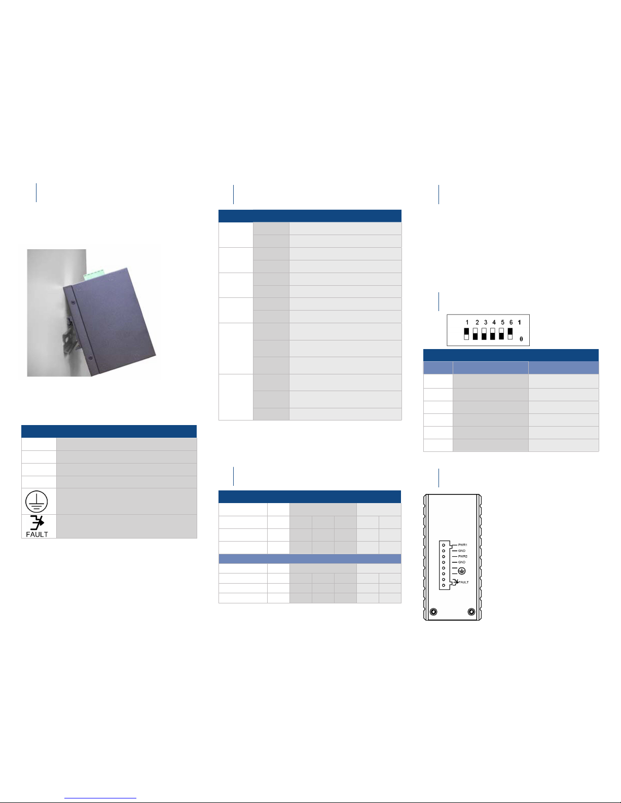
Terminal Block Assignment
PWR1 Power Input 1 (10 to 48VDC)
GND Power Ground
PWR2 Power Input 2 (10 to 48VDC)
GND Power Ground
Earth Ground
1. The relay opens if PWR1 or PWR2 fails
2. The relay opens if the Port Link is Down
(When the Link Down Alarm is Enabled)
• If redundancy is desired, be sure to connect t wo
separate power supplies by using the two DC inputs
on the terminal blocks.
• NOTE: If only one power supply is connected, the
Fault LED will remain ON. If connecting a second
power supply for redundancy, or connecting Power
Supply 1 to Power Supply 2, the Fault LED will
extinguish.
2. Connect power to the switch 10 to 48 VDC.
LED State Indication
FAULT
Steady Power or ports function abnormally
Off Power and ports function normally
PWR1
PWR2
Steady Power On (PWR stands for POWER)
Off Power Off
10/100
Steady 100 Mbps network connection
Off 10 Mbps network connection
LFP
Steady LFPT function enabled
Off LFPT function disabled
LNK/ACT
Steady
Network connection established
(LNK stands for LINK)
Flashing
Transmitting or receiving data
(ACT stands for ACTIVITY)
Off
Neither a network connection established
nor transmitting/receiving data
FDX/COL
Steady
Connection in full duplex mode
(FDX stands for FULL-DUPLEX)
Flashing
Collision occurred
(COL stands for COLLISION)
Off Connection in half-duplex mode
Link Fault of the FX Port
TX Port FX Port
LEDs PWR
100 LNK/ACT FDX/COL LNK/ACT FDX/COL
Media Converter A ON
OFF OFF OFF OFF OFF
Media Converter B ON
OFF OFF OFF OFF OFF
Link Fault of the TX Port of Media Converter A
TX Port FX Port
LEDs PWR
100 LNK/ACT FDX/COL LNK/ACT FDX/COL
Media Converter A ON
OFF OFF OFF ON ON
Media Converter B ON
OFF OFF OFF OFF OFF
DIP Switches
5
Power, Dry Contact
6
The terminals labeled Fault are
connected to a dr y contact. The
dry contact is normally closed
when either power source is
connected and active. When no
power is applied, the dr y contact is
normally open.
While only one power source is
required to power up the media
converter, two power sources offer
redundancy for mission-critical
applications. (PWR1 and PWR2)
 Loading...