

Page 1

ADAM-4570/ADAM-4571/EDG-4504
1/2/4 Port Ethernet to
RS-232/422/485 Data Gateway
User’ s Manual
Page 2

Copyright Notice
This document is copyrighted, 2001, by Advantech Co., Ltd. All rights
are reserved. Advantech Co., Ltd., reserves the right to make improvements to the products described in this manual at any time without
notice.
No part of this manual may be reproduced, copied, translated or
transmitted in any form or by any means without the prior written
permission of Advantech Co., Ltd. Information provided in this manual
is intended to be accurate and reliable. However, Advantech Co., Ltd.
assumes no responsibility for its use, nor for any infringements upon
the rights of third parties which may result from its use.
CE Notification
The ADAM-4570/ADAM-4571/EDG-4504 has passed the CE test for
environmental specifications. Test conditions for passing included the
equipment being operated within an industrial enclosure. In order to
protect the ADAM-4570/ADAM-4571/EDG-4504 system from being
damaged by ESD (Electrostatic Discharge) and EMI leakage, we
strongly recommend the use of CE-compliant industrial enclosure
products.
3nd Edition
Printed T aiwan January 2002
Page 3

Advantech Customer Services
Each and every Advantech product is built to the most exacting
specifications to ensure reliable performance in the unusual and
demanding conditions typical of industrial environments. Whether
your new Advantech equipment is destined for the laboratory or the
factory floor, you can be assured that your product will provide the
reliability and ease of operation for which the name Advantech has
come to be known.
Your satisfaction is our number one concern. Here is a guide to
Advantech’s customer services. To ensure you get the full benefit of
our services, please follow the instructions below carefully.
Technical Support
W e want you to get the maximum performance from your products. So
if you run into technical difficulties, we are here to help. For most
frequently asked questions you can easily find answers in your
product documentation. These answers are normally a lot more
detailed than the ones we can give over the phone.
Please consult this manual first. If you still cannot find the answer,
gather all the information or questions that apply to your problem and,
with the product close at hand, call your dealer. Our dealers are well
trained and ready to give you the support you need to get the most
from your Advantech products. In fact, most problems reported are
minor and are able to be easily solved over the phone.
In addition, free technical support is available from Advantech
engineers every business day. We are always ready to give advice on
application requirements or specific information on the installation and
operation of any of our products.
Page 4

Product Warranty
Advantech warrants to you, the original purchaser, that each of its
products will be free from defects in materials and workmanship for
two years from the date of purchase.
This warranty does not apply to any products which have been
repaired or altered by other than repair personnel authorized by
Advantech, or which have been subject to misuse, abuse, accident or
improper installation. Advantech assumes no liability as a consequence of such events under the terms of this Warranty.
Because of Advantech’s high quality-control standards and rigorous
testing, most of our customers never need to use our repair service. If
an Advantech product ever does prove defective, it will be repaired or
replaced at no charge during the warranty period. For out-of-warranty
repairs, you will be billed according to the cost of replacement materials, service time and freight. Please consult your dealer for more
details.
If you think you have a defective product, follow these steps:
1 .Collect all the information about the problem encountered (e.g. type
of PC, CPU speed, Advantech products used, other hardware and
software used etc.). Note anything abnormal and list any on-screen
messages you get when the problem occurs.
2 .Call your dealer and describe the problem. Please have your manual,
product, and any helpful information readily available.
3.If your product is diagnosed as defective, you have to request an
RMA number. When requesting an RMA (Return Material Authorization) number, please access ADVANTECH’ s RMA website: http://
www .advantech.com.tw/rma. If the web sever is shut down, please
contact our office directly . Y ou should fill in the “Problem Repair
Form”,describing in detail the application environment, configuration, and problems encountered. Note that error descriptions such as
“does not work” and “failure” are so general that we are then
required to apply our internal standard repair process.
4 .Carefully pack the defective product, a completely filled-out Repair
and Replacement Order Card and a photocopy of dated proof of
purchase (such as your sales receipt) in a shippable container. A
Page 5

product returned without dated proof of purchase is not eligible for
warranty service.
5.Write the RMA number visibly on the outside of the package and
ship it prepaid to your dealer.
Page 6

Contents
Chapter 1: Overview ........................................ 1
1.1 Introduction ..................................................................... 2
1.2 Features .......................................................................... 5
1.3 Specifications ................................................................. 6
1.4 Package Checklist .......................................................... 7
Chapter 2: Getting Started .............................. 9
2.1 Understanding the ADAM-4570/ADAM-4571/EDG-4504 . 11
2.1.1 Network Architecture ..................................................... 11
2.1.2 Top / Front / Rear View .................................................. 13
2.1.2.1 ADAM-4570 .............................................................. 13
2.1.2.2 ADAM-4571 .............................................................. 15
2.1.2.3 EDG-4504 ................................................................ 17
2.1.3 Stickers ......................................................................... 19
2.2 Connecting the Hardware ........................................... 20
2.2.1 Choosing a Location ...................................................... 20
2.2.1.1 ADAM-4570/4571 ..................................................... 20
2.2.1.2 EDG-4504 ................................................................ 24
2.2.2 Network Connection ....................................................... 25
2.2.3 Power Connection .......................................................... 26
2.2.4 Serial Connection ........................................................... 27
2.2.4.1 ADAM-4570/4571 ..................................................... 27
2.2.4.2 EDG-4504 ................................................................ 29
Chapter 3: Installation and Configuration .. 31
3.1 Driver and Utility Installation ....................................... 32
Page 7

3.2 Configuring the ADAM-4570/ADAM-4571/EDG-4504
The Configuration Utility ............................................. 33
3.2.1 Search for Specific ADAM-4570/ADAM-4571/EDG-4504 34
3.2.2 System Configuration ..................................................... 36
3.2.3 Network Configuration .................................................... 38
3.2.4 Port Configuration .......................................................... 39
3.2.4.1 Host/Device Idle Protection (ADAM-4570 only) ........41
3.2.5 Security Configuration .................................................... 47
3.3 Status Messages .......................................................... 48
3.3.1 Connection Diagnostic ................................................... 48
3.4 Port Mapping Utility ...................................................... 50
3.4.1 Self Test Function .......................................................... 52
3.4.2 Upgrading ADAM-4570/ADAM-4571/EDG-4504s
Firmware Download ........................................................ 54
3.4.3 Save The Configuration ................................................... 57
3.4.4 Auto-reconnect function ................................................. 58
Chapter 4: Troubleshooting ......................... 57
Page 8

Figures
Figure 2-1 Installation Flow Chart ............................................................. 10
Figure 2-2 Network Architecture(1) ......................................................... 12
Figure 2-3 Network Architecture(2) ......................................................... 12
Figure 2-4 ADAM-4570Top Panel .......................................................... 14
Figure 2-5 ADAM-4570Front Panel ........................................................14
Figure 2-6 ADAM-4570Back Panel ........................................................14
Figure 2-7 ADAM-4571Top Panel .......................................................... 16
Figure 2-8 ADAM-4571Front Panel ........................................................16
Figure 2-9 ADAM-4571Back Panel ........................................................16
Figure 2-12 EDG-4504Front Panel ........................................................... 18
Figure 2-10 EDG-4504Top Panel.............................................................. 18
Figure 2-11 EDG-4504Front Panel ........................................................... 18
Figure 2-13 Panel Mounting ........................................................................ 21
Figure 2-14 Din Rail Mounting ..................................................................... 22
Figure2-15 Piggyback Stack ...................................................................... 23
Figure 2-17 Panel Mounting ........................................................................ 24
Figure 2-16 Din Rail Mounting ..................................................................... 24
Figure 2-18 Connecting ADAM-4570/ADAM-4571/EDG-4504 series to the
hub ............................................................................................ 25
Figure 2-20 Power Connection for EDG-4504 ............................................ 26
Figure 2-19 Power Connection for ADAM-4570/4571 ............................... 26
Figure 2-21 Serial Connection for ADAM-4570/4571 ................................ 27
Figure 2-22 Serial Connection for EDG-4504 ............................................. 29
Figure 3-1 Configuration Utility ................................................................. 33
Figure 3-2 Locate all ADAM-4570/ADAM-4571/EDG-4504 ....................... 34
Figure 3-4 Locate specific ADAM-4570s ................................................. 35
Figure 3-3 Locate the desired group of ADAM-4570s .............................35
Figure 3-5 System Setting Window .......................................................... 36
Figure 3-6 Network Configuration Window ............................................. 38
Figure 3-7 Port Configuration Window .....................................................39
Page 9

Figure 3-8 ArchitectureHost idle switch mode .................................... 42
Figure 3-9 Security configuration ............................................................. 47
Figure 3-10 Status messages .................................................................... 48
Figure 3-11 Unused ports ........................................................................... 50
Figure 3-12 Assign COM port to ADAM-4570/ADAM-4571/EDG-4504 ....... 51
Figure 3-13 Warning window ......................................................................51
Figure 3-14 Test window ............................................................................. 53
Figure 3-15 Loopback test .......................................................................... 54
Figure 3-16 Update firmware window........................................................ 55
Figure 3-17 Select the file ...........................................................................55
Figure 3-18 Download firmware ................................................................. 56
Page 10

Tables
Table 2-1 ADAM-4570 LED Definition ...................................................... 13
Table 2-2 ADAM-4571 LED Definition ...................................................... 15
Table 2-3 EDG-4504 LED Definition ......................................................... 17
Page 11

1
Chapter
Overview
Page 12

1.1 Introduction
The ADAM-4570/ADAM-4571/EDG-4504 is a lightning fast and cost effective data gateway between RS232/422/485 and Ethernet interfaces. This unit immediately upgrades your existing device(s) to the Ethernet
world. Functionally transparent and efficient, the
ADAM-4570/ADAM-4571/EDG-4504 is specially
designed for remotely controlling and monitoring devices via the Internet.
The ADAM-4570/ADAM-4571/EDG-4504 provides
one, two or four RS-232/485/422 serial ports that can
each be easily configured for your needs. For increasing the reliability of systems, the ADAM-4570 also provides three significant functions: Host idle, Device idle
and Auto-reconnect. The ADAM-4570/ADAM-4571/
EDG-4504 also supports transmission speeds up to 230
Kbps, meeting the demand for today’ s high-speed exchange. Users can use a Windows utility to configure
the ADAM-4570/ADAM-4571/EDG-4504 without
need for further programming. The ADAM-4570/
ADAM-4571/EDG-4504 not only protects your current hardware investment but also ensures future network expandability . Since the protocol conversion is
transparent, all existing devices can be seamlessly integrated into the Ethernet network. Therefore, the
ADAM-4570/ADAM-4571/EDG-4504 can be used
in security systems, factory automation, SCADA, transportation and more.
The ADAM-4570/ADAM-4571/EDG-4504 integrates both your existing human-machine interface software (HMI) and RS-232/422/485 system architecture
with an Ethernet network. The result helps save cabling
Page 13

space and software development cost. The ADAM4570/ADAM-4571/EDG-4504 also provides a highperformance RISC CPU and real time operating system to reduce CPU load. These components make the
ADAM-4570/ADAM-4571/EDG-4504 more stable
and reliable. Another benefit is the ADAM-4570/
ADAM-4571/EDG-4504 allows users to remotely
download programs to a designated device via Ethernet.
This reduces the need for on-site maintenance and diagnosis. In addition, the ADAM-4570/ADAM-4571/
EDG-4504 comes with a W indows configuration and
port-mapping utility . This configuration tool can autodetect all Ethernet Data Gateway products on a local
network. It also lets users easily adjust all settings. The
port mapping utility helps to set up COM ports for one
Windows 95/98/NT/2000/XP platform. This helps users manage all ports to meet their needs.
Host/Device Idle Protection empowers the reliability of system (ADAM-4570)
For improving the stability of systems, users usually have
to spend lots of effort to build up “Redundant” functionality . Now, the ADAM-4570 provides new powerful functions that help users build up redundant systems fast and easily: The new functions are Host idle &
Device idle.
The purpose of the “Host idle switch” function is to
prevent system hang-up from occurring due to application program failure. If the application program fails,
the ADAM-4570 will cut off the connection between
the host PC and the ADAM-4570. Another PC can
then start to access the same ADAM-4570. Also, if
Page 14

the serial device or communication between the device and the
ADAM-4570 fails, the “Device Idle” function will switch the
communication port from one port to another port to keep communicating with another device automatically . Thus, another device can send data to the ADAM-4570.
Auto-reconnect after networking breaks
Sometimes, the system crashes because the ADAM-4570/
ADAM-4571/EDG-4504 is interrupted or powered-off by accident. The ADAM-4570/ADAM-4571/EDG-4504 provides
an “Auto-reconnect” function to solve this problem. When the
ADAM-4570/ADAM-4571/EDG-4504 is powered-off accidentally , the driver will keep trying to reconnect the ADAM4570/ADAM-4571/EDG-4504 automatically. When the
ADAM-4570/ADAM-4571/EDG-4504 recovers or is powered-on, due to this auto-reconnect function, the host PC can
send commands to the ADAM-4570/ADAM-4571/EDG-4504
again. This function enhances the reliability of the system.
Auto-detect Ethernet Data Gateway products
The configuration utility can search all the Ethernet Data Gateway devices on the network automatically and configure them
according to the current network status, saving your effort to
acquire the status information yourself.
Easy to diagnose the communication situation
If this test item is selected, an internal test will be done on the
RS-232 serial port, and the result (successful or failed) will be
displayed when the test is completed. If this test item is selected,
an external test will also be done to check that the connection
signals for each port are working properly . For the external test,
you will need to connect each port to a loopback tester . The test
4 ADAM-4570/ADAM-4571/EDG-4504 User’s Manual
Page 15

is divided into two parts: Signal test and Communication Parameters test. If the results are OK, users can be sure the communication quality between host PC and ADAM-4570/ 4571 is OK.
Easy to maintain by downloading firmware remotely
Advantech continually upgrades ADAM-4570/ADAM-4571/
EDG-4504’s firmware to keep pace with the ever-expanding
world of computing. Y ou can use the Download function located
on the Port Mapping utility to carry out the upgrade procedure.
Please access Advantech’s Web site to download the required
computer file and then follow the instructions.
1.2 Features
• Supports 10/100 Mbps Base-T standard
• Provides a communication redundant function to enhance the
reliability of system.
• Supports high transmission speeds up to 230 Kbps
• Supports an advanced security mechanism to avoid unautho-
rized access
• Auto-reconnect or return error when Network breaks
• Remote download firmware: Easy to maintain
• Auto-detecting Configuration Utility
• Easy managing Port Mapping Utility
• Supports Windows 95/98/NT/2000/XP driver
• Surge protection for RS-485 line and power supply
• Automatic RS-485 data flow control
Chapter 1 Introduction 5
Page 16

1.3 Specifications
• Protocol: TCP/IP
• Network Port: IEEE 802.3, IEEE 802.3u
• Interface:
Network: 10/100 BASE-T standard
Serial: RS-232, RS-422, RS-485
• Port: 1/2/4 independent RS-232/422/485 ports
• Connector:
Network: RJ-45
Serial: RJ-48 (RJ-48 to DB-9 cable provided)
• Transmission speed: 300 bps to 230 Kbps
• Parity bit: odd, even, none, space, mark
• Data bit: 5, 6, 7, 8
• Stop bit: 1, 1.5, 2
• Signals: Full Modem control signals (Doesn’t support RAS
service)
• Diagnostic LEDs:
Network: TX/RX, Link, Speed (10/100 Mbps ), Power
Serial: TX/RX, Status
• Utility Software:
Auto-detecting configuration utility
Easy-to-manage port mapping utility
• Driver Supported:
Windows 95/98/ME/NT/2000/XP
• Power Requirements: unregulated 10 to 30 Vdc with surge
protection
6 ADAM-4570/ADAM-4571/EDG-4504 User’s Manual
Page 17

• Power Consumption:
3.5 W att (ADAM-4571)
4 W att (ADAM-4570)
4.5 W att (EDG-4504)
• Placement:
DIN-rail, panel mounting, piggyback stack
(ADAM-4570/4571)
DIN-rail, panel mounting (EDG-4504)
• Operating T emperature: 0 ~ 60° C
• Storage T emperature: -20 ~ 80° C
• Operating Humidity: 20 ~ 95% (non-condensing)
• Storage Humidity: 0 ~ 95% (non-condensing)
1.4 Package Checklist
• ADAM-4570 or ADAM-4571 or EDG-4504
• CD-ROM for utility & manual
• 1/2/4 RJ-48 to DB-9 serial cables
• One loopback DB-9 tester
• Five stickers
• NYLON DIN-rail Mounting Adapter
• SECC Panel Mounting Bracket
Chapter 1 Introduction 7
Page 18

8 ADAM-4570/ADAM-4571/EDG-4504 User’s Manual
Page 19

Chapter
2
Getting Started
Page 20
In this chapter, you will be given an overview of the
ADAM-4570/ADAM-4571/EDG-4504 hardware installation
procedures. As mentioned in the previous chapter, the
ADAM-4570/ADAM-4571/EDG-4504 comes ready for all
network connections, including Ethernet, and RS-232/422/485
port connections.
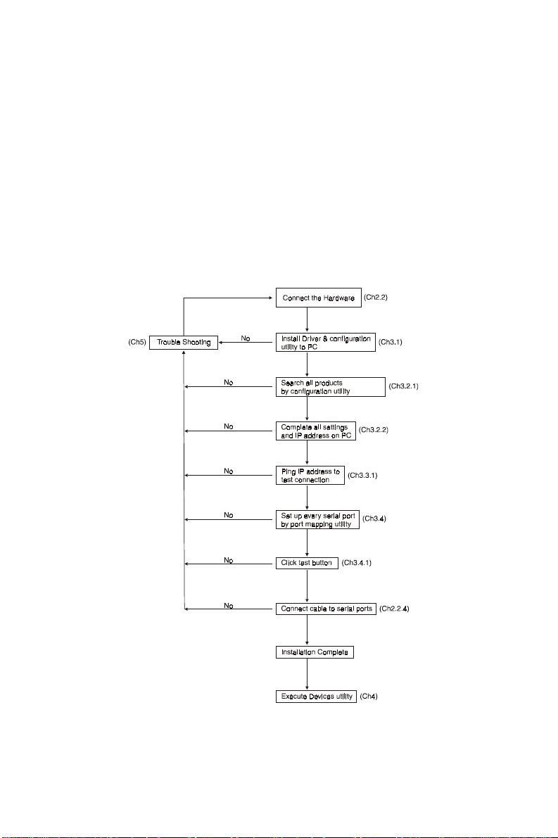
We begin this chapter with a brief showing the installation
procedure. Y ou can take flow chart for reference.
Figure2-1 Installation Flow Chart
10 ADAM-4570/ADAM-4571/EDG-4504 User’s Manual
Page 21

2.1 Understanding the ADAM-4570/ADAM-4571/EDG-4504
The ADAM-4570/ADAM-4571/EDG-4504 is an advanced
data gateway unit. It extends traditional COM ports of a PC
with access over a TCP/IP network. Through networking, you
can control and monitor remote serial devices either over a LAN
or over the W AN.
Since the ADAM-4570/ADAM-4571/EDG-4504 is connected
through a TCPIP network, you will need to know some basic
facts about networking in order to get the server hooked up
correctly .
2.1.1 Network Architecture
Traditional serial port communication uses a COM port board
that slides into one of the slots at the back of your PC. In this
case, only the computer containing the board can access the
serial port. With the ADAM-4570/ADAM-4571/EDG-4504,
you are now able to access the COM port from a distance through
local area network. The ADAM-4570/ADAM-4571/EDG4504 can be integrated within the network architecture of any
protocol. Note, all serial devices which are connected to the
port must have the same protocol running and the same transmission speed. Connect devices running different protocols to
different ports of the ADAM-4570/ADAM-4571/EDG-4504.
Chapter 2 Getting Started 11
Page 22
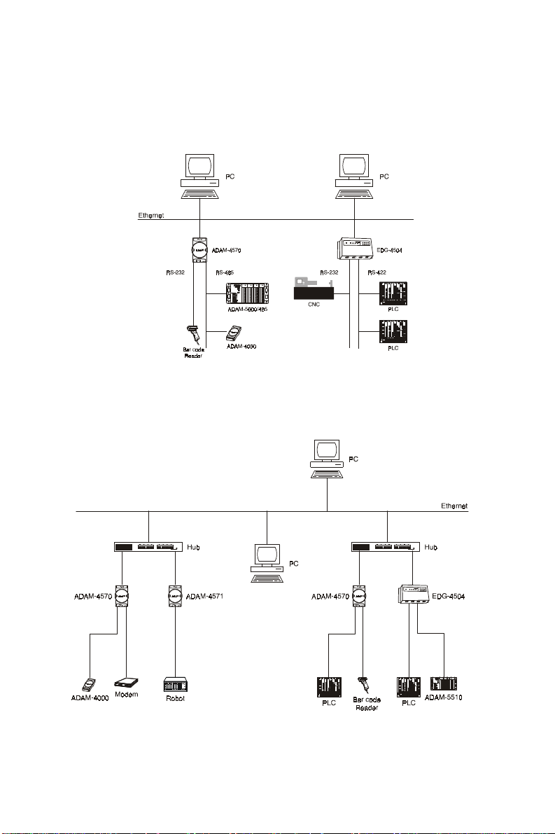
The following illustration shows the network architecture as below:
Figure 2-2 Network Architecture(1)
Figure 2-3 Network Architecture(2)
12 ADAM-4570/ADAM-4571/EDG-4504 User’s Manual
Page 23

2.1.2 Top / Fr ont / Rear View
2.1.2.1 ADAM-4570
There are five network status LEDs located on the top panel of
ADAM-4570, each with its own specific function.
LED Color Status Description
Red
Status/Power
Green
Red
Speed/Link
Green
Red
Tx/Rx
(Ethernet)
Green
Red
Tx/Rx (port1)
Green
Red
Tx/Rx (port2)
Green
ON Heartbeat (1 time/sec)
OFF Not working
ON Power ON
OFF Power OFF
ON 100 Mbps speed
OFF 10 Mbps speed
ON Valid network link
OFF Invalid network link
ON Ethernet data b eing transmitted
OFF No data being transmitted
ON Data being received
OFF N o Data being received
ON Serial port data being transmitted
OFF No data being received
ON Data being received
OFF N o data being received
ON Data being transmitted
OFF No data being tr ansmitted
ON Data being received
OFF N o data being received
T able 2-1 ADAM-4570 LED Definition
Chapter 2 Getting Started 13
Page 24

Figure 2-4 ADAM-4570—Top Panel
Figure 2-5 ADAM-4570—Front Panel
Figure 2-6 ADAM-4570—Back Panel
14 ADAM-4570/ADAM-4571/EDG-4504 User’s Manual
Page 25

2.1.2.2 ADAM-4571
There are four LEDs located on the top panel of ADAM-4571,
each with its own specific function.
LE D Color Status Description
Red
Status/Power
Green
Red
Speed/Link
Green
Red
Tx/Rx
(Ethernet)
Green
Red
Tx/Rx (port1)
Green
ON Heart beat (1 time/sec)
OFF Not working
ON Power ON
OFF Power OFF
ON 100 Mbps speed
OFF 10 Mbps speed
ON Valid network link
OFF Invalid network link
ON Ethernet data b eing transmitted
OFF No data being transmitted
ON Data being received
OFF N o Data being received
ON Data being transmitted
OFF No data being tr ansmitted
ON Data being received
OFF N o data being received
Table 2-2 ADAM-4571 LED Definition
Chapter 2 Getting Started 15
Page 26

Figure 2-7 ADAM-4571—Top Panel
Figure 2-8 ADAM-4571—Front Panel
Figure 2-9 ADAM-4571—Back Panel
16 ADAM-4570/ADAM-4571/EDG-4504 User’s Manual
Page 27

2.1.2.3 EDG-4504
There are 13 LEDs located on the top panel of EDG-4504,
each with its own specific function.
LE D Statu s Description
Status
10M
100M
TX (Ethernet)
RX (Ethernet)
TX (port N)
N=1 ~4
RX (po r t N)
N= 1~ 4
ON Heart beat (1 time/se c)
OFF Not working
ON 10 Mbps speed
OFF Invalid 10 Mbps Network link
ON 100 Mbps speed
OFF Invalid 100 Mbps Network link
ON Ethernet data be ing received
OFF N o data being transmitted
ON Ethernet da ta being received
OFF N o data being rec eived
ON Serial port da ta being transmitted
O F F N o data being rec eived
ON Serial port da ta being transmitted
O F F N o data being rec eived
T able 2-3 EDG-4504 LED Definition
Chapter 2 Getting Started 17
Page 28

Figure 2-10 EDG-4504—Top Panel
Figure 2-11 EDG-4504—Front Panel
Figure 2-12 EDG-4504—Front Panel
18 ADAM-4570/ADAM-4571/EDG-4504 User’s Manual
Page 29

2.1.3 Stickers
If you forgot the IP addresses of specific ADAM-4570/ADAM4571/EDG-4504s or where the host PC is mapped to the
ADAM-4570 port, we have provided five stickers for you to
note the IP addresses and place in a secure location. For example,
172.20.20.5: The IP address of specific ADAM-4570
160.59.20.89: The IP address of the specific host PC mapped
to this port.
Chapter 2 Getting Started 19
Page 30

2.2 Connecting the Hardware
Next, we will explain how to find a proper location for your
EDG COMPort series, and then explain how to connect to the
network, hook up the power cable, and connect to the ADAM4570/ADAM-4571/EDG-4504’s serial port.
Note: Before you install ADAM-4570/ADAM-4571/EDG-
4504, you can install other communication cards first.
2.2.1 Choosing a Location
2.2.1.1 ADAM-4570/4571
Due to its versatility and innovative design, the ADAM-4570/
ADAM-4571 can be:
• fixed to a panel mount
• fixed to a DIN Rail.
• Piggyback Stack
20 ADAM-4570/ADAM-4571/EDG-4504 User’s Manual
Page 31

Panel Mounting
The ADAM-4570/ADAM-4571 can be attached to a wall using the included metal brackets. Each bracket comes with four
screws; first attach the brackets to the bottom of the ADAM4570/ADAM-4571. Next, screw each bracket to a wall.
Figure 2-13 Panel Mounting
Chapter 2 Getting Started 21
Page 32

DIN Rail Mounting
Y ou can mount the ADAM-4570/ADAM-4571 on a standard
DIN Rail. First, using two screws, attach the metal plate to the
DIN Rail bracket. Because the screw heads are beveled, the
tops of the screws will be flush with the metal plate. Din Rail
Mounting Brackets—Orientation of Metal Plates
Y ou can now screw the metal plate with the DIN rail bracket
assembly to the bottom of the server is a more convenient way .
Next, use the remaining screws to put the metal plate on the
bottom of the ADAM-4570/ADAM-4571.
Figure 2-14 Din Rail Mounting
22 ADAM-4570/ADAM-4571/EDG-4504 User’s Manual
Page 33

Piggyback Stack
ADAM-4570/ADAM-4571 can be stacked as seen in the figure below .
Figure2-15 Piggyback Stack
Chapter 2 Getting Started 23
Page 34

2.2.1.2 EDG-4504
Figure 2-16 Din Rail Mounting
Figure 2-17 Panel Mounting
24 ADAM-4570/ADAM-4571/EDG-4504 User’s Manual
Page 35

2.2.2 Network Connection
There are two ways to use the 10/100Base-T Ethernet connector located on the ADAM-4570/ADAM-4571/EDG-4504 :
1.For Local Area Network (LAN) applications using the
ADAM-4570/ADAM-4571/EDG-4504, you will simply plug
one end of your Ethernetcable into the 10/100Base-T connector, and the other end into the hub connected to your network.
2.When installing and configuring, you will find it convenient
to hook the ADAM-4570/ADAM-4571/EDG-4504 directly
to your computer’s Ethernet card. T o do this you will need to
use a “crossed-cable”, such as the one supplied with your
server.
Cabling requirements for the Ethernet side
Use an RJ-45 connector to connect the Ethernet port of the
ADAM-4570/ADAM-4571/EDG-4504 to the network hub.
The cable for connection should be Category 3 (for 10Mbps
data rate) or Category 5 (for 100 Mbps data rate) UTP/STP
cable, which is compliant with EIA/TIA 586 specifications.
Maximum length between the hub and any ADAM-4570/
ADAM-4571/EDG-4504 is up to 100 meters (ca. 300 ft).
Figure 2-18 Connecting ADAM-4570/ADAM-4571/EDG-4504 series to
the hub
Chapter 2 Getting Started 25
Page 36

2.2.3 Power Connection
Y ou should take the following steps to connect ADAM-4570/
ADAM-4571/EDG-4504 power.
1. Connect the power cable to 2-pin connector
2. Connect power cable to power adapter
Figure 2-19 Power Connection for ADAM-4570/4571
Figure 2-20 Power Connection for EDG-4504
If the ADAM-4570/ADAM-4571/EDG-4504 is working properly , the green power LED will light up , indicating that the
ADAM-4570/ADAM-4571/EDG-4504 is receiving power.
Furthermore, the ADAM-4570/ADAM-4571/EDG-4504 provides surge protection to protect it from being damaged by overvoltage, a 34V surge protection is added to the power end and
an 18V surge protection is for the RS-422/485 end.
26 ADAM-4570/ADAM-4571/EDG-4504 User’s Manual
Page 37

2.2.4 Serial Connection
2.2.4.1 ADAM-4570/4571
The model of the ADAM-4570/4571 that you purchased has
RJ-48 serial ports on the bottom of module. Depending on your
serial device and serial interfaces, there are two options:
1. For an RS-232/422/485 port you may use a RJ-48 to
DB-9 cable which we supply to connect your serial device to
the ADAM-4570/4571. Simply plug one end of the cable
into the jack, and plug the other end into the serial port jack
on your serial device.
2. Refer to the following table for details on serial cable RJ-48 to
DB-9 pinouts.
Figure 2-21 Serial Connection for ADAM-4570/4571
Chapter 2 Getting Started 27
Page 38

RJ-48
PIN Name DCD RX TX DTR GND DSR RTS CTS RI
RJ- 48 1 2 3 4 5 6 7 8 9
DB-9
28 ADAM-4570/ADAM-4571/EDG-4504 User’s Manual
Page 39

2.2.4.2 EDG-4504
The model of the EDG-4504 that you purchased has DB-9 serial ports on the bottom of module. Depending on your serial
device and serial interfaces, there are two options:
1. For an RS-232/422/485 port you may use a DB-9 cable to
connect your serial device to the EDG-4504. Simply plug
one end of the cable into the jack, and plug the other end into
the serial port jack on your serial device.
2. The DB-9 pinouts is the same as ADAM-4570/4571
Figure 2-22 Serial Connection for EDG-4504
Chapter 2 Getting Started 29
Page 40

30 ADAM-4570/ADAM-4571/EDG-4504 User’s Manual
Page 41

3
Chapter
Installation and Configuration
Page 42

3.1 Driver and Utility Installation
In order to use a PC via an Ethernet network to control serial
devices connected to the ADAM-4570/ADAM-4571/EDG4504, you must first have a host running Windows 95/98/ME/
NT/2000/XP . This type of application also requires the host to
have an Ethernet card and TCP/IP protocol installed. Following
are the installation instructions to set up the ADAM-4570/
ADAM-4571/EDG-4504.
1.Insert the Advantech industrial communication CD-ROM into
the drive (e.g. D:\) on the host PC. Change the host computer’s default drive from C: to D:
2.Use your Windows Explorer or the W indows Run command
to execute the Setup program (the path for the Setup program
on the CD-ROM should be D:\ADAM4570\utility&driver\
portmaputility1.01\setup.exe, if your default floppy drive is D:).
3.The Setup program will specify a default installation path,
C:\Program Files\Advantech\EDG COMport\1, 2 and 4
ports Mapping utility. If a new destination path is necessary ,
just click the Browse button to change to another path. After
you have specified the installation path, click the Next button.
4.Use your Windows Explorer or the W indows Run command
to execute the Setup program.the path for the Setup program
on the CD-ROM should be D:\ADAM-4570\utility&driver\
configutility1.01\setup.exe, if your default floppy drive is D:).
Use the same way to execute the Setup program. The default
path is C:\Program Files\Advantech\EDG COMport\1, 2
and 4 Configuration utility.
5.After setup has copied all program files to your computer,
click the Finish button to finish the installation.
32 ADAM-4570/ADAM-4571/EDG-4504 User’s Manual
Page 43

6.The configuration utility will search for the ADAM-4570/
ADAM-4571/EDG-4504 devices on your local network.
Figure 3-1 Configuration Utility
3.2 Configuring the ADAM-4570/ADAM-4571/EDG-4504 —
The Configuration Utility
The ADAM-4570/ADAM-4571/EDG-4504 provides easy
Windows configuration through Ethernet connection. This
Windows utility searches all the ADAM-4570/ADAM-4571/
EDG-4504 and devices on the network automatically and you
can configure various parameters for TCP/IP configuration easily . For secure administration, it can also restrict the access rights
for configuration to only one host PC to enhance network security . With this secure function enabled, other PCs will not have
permission for configuration. The Windows utility consists of four
functional categories: System, Network, Port, and Security which
are presented on the toolbar of the configuration utility .
Note: When you have finished the configuration of these set-
tings for each category , please follow the steps described
below to make thse settings effective on the ADAM-4570/
ADAM-4571/EDG-4504.
è è
Chapter 3: Installation and Configuration 33
Page 44

3.2.1 Search for Specific ADAM-4570/ADAM-4571/
EDG-4504
If you want to locate specific ADAM-4570/ADAM-4571/EDG4504s, the configuration utility provides a “Locate” function to
assist you. Y ou can select all the ADAM-4570/ADAM-4571/
EDG-4504 devices (see Figure 3-2) or select a group of ADAM4570s (see Figure 3-3) or just select one ADAM-4570 (see
Figure 3-4). When you select a specific device, the LED that
stands for “Status” will glow for 8 minutes. When you select
another device, the original “Status” LED will turn off. Please
follow these steps:
1.Select “All Devices” and click “Locate”
2.The “Status” LED of all devices will turn on
Figure 3-2 Locate all ADAM-4570/ADAM-4571/EDG-4504
1.Select “Designated” and select “ADAM-4570”
2.Click “Locate”
34 ADAM-4570/ADAM-4571/EDG-4504 User’s Manual
Page 45

3.The “Status” LED of all ADAM-4570s on the LAN will turn
on
4.It’s the same way to locate one device.
Figure 3-3 Locate the desired group of ADAM-4570s
Figure 3-4 Locate specific ADAM-4570s
Chapter 3: Installation and Configuration 35
Page 46

3.2.2 System Configuration
Figure 3-5 System Setting Window
Configuration utility can only search the ADAM-4570/ADAM4571/EDG-4504 devices on the local network segment and
cannot search beyond a r outer or gateway. Make sure that all
the ADAM-4570/ADAM-4571/EDG-4504 devices that you
want to monitor must reside on the same local network segment
with the host PC.
Ethernet Data Gateway
In this column, you will see all the found ADAM-4570/ADAM4571/EDG-4504 devices are listed when you use the configuration utility to auto-search ADAM-4570/ADAM-4571/EDG4504 devices. The specific number following each ADAM-4570/
ADAM-4571/EDG-4504 device is its MAC Address. The MAC
Address is what helps the local system to identify and locate
each Ethernet data gateway device. This MAC Address is already set before delivery from factory , hence no need for further
configuration.
36 ADAM-4570/ADAM-4571/EDG-4504 User’s Manual
Page 47

Device Name
Configuration utility provides a default name for device to distinguish a specific ADAM-4570/ADAM-4571/EDG-4504 from
other ADAM-4570/ADAM-4571/EDG-4504. Y ou can update
the default device name based on your application. Names longer
than 128 characters cannot be used. It is best to choose a name
you can remember .
Device Description
This field is to record the function, application and other information for each ADAM-4570/ADAM-4571/EDG-4504 device
in more detail for easy management and maintenance. Y ou are
allowed to describe in your own words.
Firmware version
In this field, the configuration utility represents the firmware version of the ADAM-4570/ADAM-4571/EDG-4504. Y ou might
need to refer to the firmware version to determine functions available on the ADAM-4570/ADAM-4571/EDG-4504 device. In
case of problems that might concern the firmware version, please
provide the firmware version number to our Customer Service.
T ype
Each ADAM-4570/ADAM-4571/EDG-4504 offers three serial interfaces, RS-232, RS-485 and RS-422. You can use any
one of these serial interfaces according to your requirements.
Chapter 3: Installation and Configuration 37
Page 48

3.2.3 Network Configuration
Figure 3-6 Network Configuration Window
MAC Address
This does not need configuration.
Link Speed
This function will show the current linking speed to be either
10Mbps or 100Mbps. However, the utility will auto-detect the
current transmission speed on the network segment and set the
transmission speed for the device accordingly without your further efforts.
Duplex Mode
The utility will detect the current transmission mode (half-duplex
or full-duplex) on the network segment, and set the transmission
mode for the device accordingly without your further efforts.
38 ADAM-4570/ADAM-4571/EDG-4504 User’s Manual
Page 49

IP address, Subnet Mask, Default Gateway
The IP address identifies your ADAM-4570/ADAM-4571/
EDG-4504 device on the global network. Each ADAM-4570/
ADAM-4571/EDG-4504 has same default IP address 10.0.0.1.
Obtain a specific IP address from your network administrator
and then configure each ADAM-4570/ADAM-4571/EDG-4504
with the individual IP address.
Note: The ADAM-4570/ADAM-4571/EDG-4504 does not
support auto IP address configured by DHCP server .
3.2.4 Port Configuration
Figure 3-7 Port Configuration Window
Chapter 3: Installation and Configuration 39
Page 50

Name
To specify which port on the ADAM-4570/ADAM-4571/EDG4504 is to be connected to the serial device.
Description
Y ou can give more detailed description of the function of the
port for easy management and maintenance. Descriptions longer
than 128 characters cannot be used.
T ype
Each ADAM-4570/ADAM-4571/EDG-4504 offers three kinds
of serial interfaces, RS-232, RS-485 and RS-422. Y ou can use
any of the three serial interfaces according to your requirements.
Parity
The ADAM-4570/ADAM-4571/EDG-4504 provides five
options: Even, Odd, None, Space, Mark.
Flow Control
The ADAM-4570/ADAM-4571/EDG-4504 provides four
options: None, Xon/Xoff, R TS/CTS, DTR/DSR.
Data Bits
The ADAM-4570/ADAM-4571/EDG-4504 provides four
options: 5, 6, 7 or 8.
Stop Bits
The ADAM-4570/ADAM-4571/EDG-4504 provides three
options: 1, 1.5 or 2.
Baud Rate
The ADAM-4570/ADAM-4571/EDG-4504 supports baud
rates from 300 to 230,000 bps.
40 ADAM-4570/ADAM-4571/EDG-4504 User’s Manual
Page 51

3.2.4.1 Host/Device Idle Protection (ADAM-4570 only)
When building up a system, users sometimes face the following
problems. The system crashes because the serial/Host device
breaks down; the application program fails or the cable between
the host device and the ADAM-4570 breaks etc. For keeping
the stability of system, the users usually have to spend lots of
efforts to build up “Redundant” function. Now the ADAM-4570
provides new powerful functions to help users to build up it fast
and easily . Focusing on Host PC, serial device, ADAM-4570,
the new functions are: Host idle switch, device idle switch and
auto-reconnect (refer to Chapter 3.4.4).
Host Idle Switch Mode
When the application program which is running in host PC fails,
the ADAM-4570 and the serial device always “Hang up”. The
data can not be sent to other PC. The purpose of the “Host idle
switch” mode is to prevent this system hang-up from occurring
due to the above problems. If the application program fails, the
ADAM-4570 will cut off the connection between the host PC
and the ADAM-4570. Another PC can then start to access the
same ADAM-4570. Below illustrates the behavior of the
ADAM-4570.
Chapter 3: Installation and Configuration 41
Page 52

1. Users set up the time period that the ADAM-4570 waits for
the host PC to send commands.
2. If the time is over the set time, the ADAM-4570 will cut the
connection between host A and the ADAM-4570.
3. Host B then starts to set up a connection between host B and
the ADAM-4570.
4. If host B is in the authority list, it can access the ADAM-
4570.
H ost A
Ethern et
Figure 3-8: Architecture—Host idle switch mode
A D A M -45 70
PL C or A D A M
H ost B
42 ADAM-4570/ADAM-4571/EDG-4504 User’s Manual
Page 53
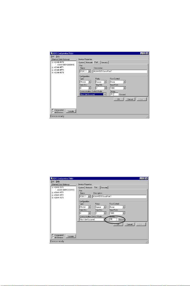
Configuration Steps
1. Select “Host Idle” mode.
2. Key-in the Timing.
The “Timing” is the time that the ADAM-4570 will wait to
receive commands from the host PC. If the ADAM-4570 does
not receive any commands from the host PC over this user set
period of time, the ADAM-4570 will automatically cut off the
connection. The time limitation (seconds) ranges from 1 ~
4095
Chapter 3: Installation and Configuration 43
Page 54

3. Make sure that Host B is in the authority list.
Device Idle Switch Mode
When the serial device or communication between the device
and the ADAM-4570 fails, the data can not be sent to the
host PC in the set time period. The purpose of the “Device
idle switch” mode is to provide another communication link to
the serial device. If the serial device or communication between the device and the ADAM-4570 fails, the ADAM4570 will switch the communication port from port 1 to port 2
to keep communicating with device B automatically . Thus, device B can send data to ADAM-4570’ s port 2. An illustration
of this configuration follows.
1. User sets up COM 25 in host PC to receive the data.
2. User sets up the period of time the ADAM-4570 waits for
device A to send data.
3. If the time is more than the set time, the ADAM-4570 will
switch the communication port from port 1 to port 2.
4. Device B can send data to the ADAM-4570 via port2.
44 ADAM-4570/ADAM-4571/EDG-4504 User’s Manual
Page 55

5. The ADAM-4570 will transmit data to the same COM 25 of
the host PC.
The CO M 25 of host PC
receives the data
D ev ice A
Ethernet
ADAM-4570
Port 1
Po r t 2
Device B
Chapter 3: Installation and Configuration 45
Page 56

Configuration Steps
1. Select “Device Idle” mode.
2. Key-in the Timing.
The “Timing” is the period of time that the ADAM-4570 will
wait to receive data from the serial device. If the ADAM4570 does not receive any data from the device over the period of time the user sets up, the ADAM-4570 will switch the
communication port to another one. The time limitation (seconds) is from 1 ~ 4095
46 ADAM-4570/ADAM-4571/EDG-4504 User’s Manual
Page 57

3.2.5 Security Configuration
Figure 3-9 Security configuration
Only configure the authorized IP
This option is enabled in order to protect all configuration
settings from being changed inadvertently .
Allow any IP to access
If this option is enabled, any PC can access data from this
ADAM-4570/ADAM-4571/EDG-4504.
The specified IP which can access
If you do not want many PCs to have the access right, you can
limit at most 32 PCs to access data from this ADAM-4570/
ADAM-4571/EDG-4504.
Chapter 3: Installation and Configuration 47
Page 58

3.3 Status Messages
The status message shown at the bottom of the utility window
reflects the current status of ADAM-4570/ADAM-4571/EDG-
4504.
Figure 3-10 Status messages
“Read”
The configuration utility has found the ADAM-4570/ADAM4571/EDG-4504 and it is ready for use.
“Searching EDG COMport”
The configuration utility is searching the ADAM-4570/ADAM4571/EDG-4504
“Querying DATA from EDG COMport”
The configuration utility is getting data from the ADAM-4570/
ADAM-4571/EDG-4504.
48 ADAM-4570/ADAM-4571/EDG-4504 User’s Manual
Page 59

“Device Ready”
The ADAM-4570/ADAM-4571/EDG-4504 is ready to be
configured and is now waiting for acknowledgement from the
device.
“Lost Connection from the Device”
Due to device shut down or network failure, the configuration
utility has lost connection after 5 seconds.
“Fail to apply this setting to the device”
Specific settings are not accepted by ADAM-4570/ADAM4571/EDG-4504.
“The device fails to respond”
The connected device does not respond.
“Fail to reset the device”
Fail to reset the ADAM-4570/ADAM-4571/EDG-4504.
3.3.1 Connection Diagnostic
When you complete the configuration of your ADAM-4570/
ADAM-4571/EDG-4504s, you can follow the steps to check if
the ADAM-4570/ADAM-4571/EDG-4504 connects to network or not.
1.Execute the Microsoft DOS program.
2.Execute “PING” command and type your IP address of
ADAM-4570/ADAM-4571/EDG-4504. If ADAM-4570/
ADAM-4571/EDG-4504 connects to your network, it will
display in the screen. If the ADAM-4570/ADAM-4571/
EDG-4504 cannot be pinged, you will need to ask someone
Chapter 3: Installation and Configuration 49
Page 60

at the remote site to check and see if the power is on, and
make sure that the connection is okay .
3.4 Port Mapping Utility
The purpose of the port mapping utility is to help you manage all
ports which are in one Windows NT or W indows 2000 platform. The utility displays three types of ports: Used ports, Un-
used ports and ADAM-4570/ADAM-4571/EDG-4504 ports.
Please follow the steps.
1.Click the UNUSED PORTS item and select the port which
you want to configure.
Figure 3-11 Unused ports
2.Click ADD button to assign the COMport to the specific
ADAM-4570/ADAM-4571/EDG-4504.
3.Type IP address of the ADAM-4570/ADAM-4571/EDG4504 and select ports.
50 ADAM-4570/ADAM-4571/EDG-4504 User’s Manual
Page 61

Figure 3-12 Assign COM port to ADAM-4570/ADAM-4571/EDG-4504
Note: If you assigned different COMport to the same ADAM 4570’s port. The dialog box will appear to remind you.
Figure 3-13 Warning window
4. The port has been added into ADAM-4570/ADAM-4571/
EDG-4504
5. If you want to remove the COMport, click DELETE to re-
move this.
Chapter 3: Installation and Configuration 51
Page 62

6. After you complete the configuration, click ”Apply”.
3.4.1 Self Test Function
The purpose of this test is to make sure the communication from
host PC to ADAM -4570 is OK. If there is still an error, you
can check the communication from the ADAM-4570/ADAM4571/EDG-4504 to the serial devices.
If the test is selected, an external test will be done to check that
the connection signals for each port are working properly . For
the test, you will need to connect each port to a loopback tester
(provided in the package). Refer to the following chart for the
specifications of this loopback tester . The loopback test only
applies to RS-232 mode. The test is divided into two parts:
Signal test and Communication Parameters test.
52 ADAM-4570/ADAM-4571/EDG-4504 User’s Manual
Page 63

1. Click the T est button in the Port Mapping utility .
Figure 3-14 Test window
Signal Test
• RTS CTS: Check the RTS and CTS signals between
è
two ports.
• DTR RI: Check the DTR and RI signal between two
è
ports.
• DTR DSR: Check the DTR and DSR signal between two
è
ports.
• DTR DCD: Check the DTR and DCD signal between two
è
ports.
Communication Parameters T est
• Baud rate: From 50 bps to 230 Kbps
• Data bit: 5,6, 7, 8
• Stop bit: 1, 1.5, 2
• Parity: odd, even, none, space, mark
Chapter 3: Installation and Configuration 53
Page 64

2.Click OK button to return to the port mapping window . All
the ports in the ADAM-4570/ADAM-4571/EDG-4504 are
tested ok.
Figure 3-15 Loopback test
3.4.2 Upgrading ADAM-4570/ADAM-4571/EDG4504’s Firmwar e Download
Advantech continually upgrades its firmware to keep pace with
the ever-expanding world of computing. Y ou can use the Download function located on Port Mapping utility to carry out the
upgrade procedure. Please access Advantech’s Web site at
http://www.advantech.com to download the required computer
file and then follow these instructions.
54 ADAM-4570/ADAM-4571/EDG-4504 User’s Manual
Page 65

1.Click on the toolbar Update FW icon.
Figure 3-16 Update firmware window
2.Locate and then select the filename of the firmware that
you downloaded.
Figure 3-17 Select the file
Chapter 3: Installation and Configuration 55
Page 66

3.After downloading firmware completely, click on the Reboot
button. The ADAM-4570/ADAM-4571/EDG-4504 will restart automati cally .
Figure 3-18 Download firmware
Note: After clicking Reboot button, configuration utility will not
reboot ADAM-4570/ADAM-4571/EDG-4504 untill no
application program access this ADAM-4570/ADAM4571/EDG-4504.
56 ADAM-4570/ADAM-4571/EDG-4504 User’s Manual
Page 67

3.4.3 Save The Configuration
If you want to save or recover the configuration, you can select
the “Import/Export” items.
1.a. Select “File”
b. Select “Import” or “Export”
2.Save or open the configurations
Chapter 3: Installation and Configuration 57
Page 68

3.4.4 Auto-reconnect function
Sometimes, the system crashes because the ADAM-4570 is interrupted or is powered-off by accident. Users want the host
PC to re-connect to the ADAM-4570 automatically after such
an occurrence. The ADAM-4570 provides an “Auto-reconnect”
function to solve this problem. When the ADAM-4570 is powered-off accidentally , the driver will keep trying to reconnect the
ADAM-4570 automatically. When the ADAM-4570 recovers
or is powered-on, due to this auto-reconnect function, the host
PC’s commands will be received by the ADAM-4570 again.
This function enhances the reliability of the system.
W arning: If you want to enable the “Auto-reconnect” function,
please note that you can NOT enable the “Host idle” function at
the same time. The same also applies in reverse, e.g. if you want
to enable the “Host idle” function, you also can NOT enable the
“Auto-reconnect” function at the same time.
58 ADAM-4570/ADAM-4571/EDG-4504 User’s Manual
Page 69

4
Chapter
Troubleshooting
Page 70

This chapter explains how to solve some of the most common
problems you could encounter while using ADAM-4570/
ADAM-4571/EDG-4504. If you are still having problems after
reading this chapter, contact your dealer , or e-mail Advantech
for help.
“Configuration Utility can not find ADAM-4570/ADAM4571/EDG-4504”
1.Check POWER LED. If it is off, you have to check :
• Make sure the ADAM-4570/ADAM-4571/EDG-4504
power cable is plugged in, and the server is receiving
power.
• Check that the server’s network connector is plugged in
properly .
• Make sure your computer is properly connected to the
network.
• The input voltage is between +10V and +30V
2.Check LINK LED. If it is off, you have to check:
• Network Connection is OK
• Make sure your network is 10/100 Mbps
3.If the above are completed, it means the ADAM-4570/
ADAM-4571/EDG-4504 is okay . Next, check to see if the
ADAM-4570/ADAM-4571/EDG-4504 and the host are on
the same local area network.
“Configuration utility can find ADAM-4570/ADAM-4571/
EDG-4504 but cannot access ADAM-4570/ADAM-4571/
EDG-4504”
58 ADAM-4570/ADAM-4571/EDG-4504 User’ s Manual
Page 71

For security reasons, and to simplify operations, users can
give the access right to specific PC. Only these PCs can get
data from ADAM-4570/ADAM-4571/EDG-4504. Thus, if
while using the ADAM-4570/ADAM-4571/EDG-4504, it is
advised that you check to see if your PC is on the access right
list.
“Cannot change the IP address or other server properties”
The network administrator is the only one allowed to modify
the ADAM-4570/ADAM-4571/EDG-4504’ s configuration.
Keep in mind, even when multiple hosts share the same network, administrative access is still protected. If you need to
change any configu ration settings, ask your network administrator for assis tance.
“The host PC can acess the ADAM-4570/ADAM-4571/
EDG-4504 at this local site but later moves the ADAM4570/ADAM-4571/EDG-4504 to a remote site that PC cannot access.”
Due differing network interface connections, your IP address
might have changed, and as a result, you are no longer on the
ADAM-4570/ADAM-4571/EDG-4504’ s Access Control list.
T o resolve this issue:
1.Confirm your IP address with the ADAM-4570/ADAM4571/EDG-4504.
2.As the network administrator to set up the server con- figuration so that you are on the ADAM-4570/ADAM-4571/
EDG-4504’s Access Control list.
Chapter 4 Troubleshooting 59
Page 72

60 ADAM-4570/ADAM-4571/EDG-4504 User’ s Manual
 Loading...