

Page 1

DNS-3200
3U Dual Intel® Xeon™ Storage
Server with 15 SATA Channels
User’s Manual
Page 2

Copyright
The documentation and the software included with this product are copyrighted 2005 by Advantech Co., Ltd. All rights are reserved. Advantech
Co., Ltd. reserves the right to make improvements in the products
described in this manual at any time without notice. No part of this manual may be reproduced, copied, translated or transmitted in any form or
by any means without the prior written permission of Advantech Co., Ltd.
Information provided in this manual is intended to be accurate and reliable. However, Advantech Co., Ltd. assumes no responsibility for its use,
nor for any infringements of the rights of third parties, which may result
from its use.
Acknowledgements
Intel and Pentium are trademarks of Intel Corporation.
Microsoft Windows and MS-DOS are registered trademarks of Microsoft
Corp.
All other product names or trademarks are properties of their respective
owners.
Part No. 2002320010 1st Edition
Printed in Taiwan August 2005
DNS-3200 User’s Manual ii
Page 3

Product Warranty (3 years)
Advantech warrants to you, the original purchaser, that each of its products will be free from defects in materials and workmanship for three
years from the date of purchase.
This warranty does not apply to any products which have been repaired or
altered by persons other than repair personnel authorized by Advantech,
or which have been subject to misuse, abuse, accident or improper installation. Advantech assumes no liability under the terms of this warranty as
a consequence of such events.
Because of Advantech’s high quality-control standards and rigorous testing, most of our customers never need to use our repair service. If an
Advantech product is defective, it will be repaired or replaced at no
charge during the warranty period. For out-of-warranty repairs, you will
be billed according to the cost of replacement materials, service time and
freight. Please consult your dealer for more details.
If you think you have a defective product, follow these steps:
1. Collect all the information about the problem encountered. (For
example, CPU speed, Advantech products used, other hardware
and software used, etc.) Note anything abnormal and list any
onscreen messages you get when the problem occurs.
2. Call your dealer and describe the problem. Please have your manual, product, and any helpful information readily available.
3. If your product is diagnosed as defective, obtain an RMA (return
merchandise authorization) number from your dealer. This allows
us to process your return more quickly.
4. Carefully pack the defective product, a fully-completed Repair and
Replacement Order Card and a photocopy proof of purchase date
(such as your sales receipt) in a shippable container. A product
returned without proof of the purchase date is not eligible for warranty service.
5. Write the RMA number visibly on the outside of the package and
ship it prepaid to your dealer.
iii
Page 4

Declaration of Conformity
CE
This product has passed the CE test for environmental specifications
when shielded cables are used for external wiring. We recommend the use
of shielded cables. This kind of cable is available from Advantech. Please
contact your local supplier for ordering information.
CE
This product has passed the CE test for environmental specifications. Test
conditions for passing included the equipment being operated within an
industrial enclosure. In order to protect the product from being damaged
by ESD (Electrostatic Discharge) and EMI leakage, we strongly recommend the use of CE-compliant industrial enclosure products.
FCC Class A
Note: This equipment has been tested and found to comply with the limits
for a Class A digital device, pursuant to part 15 of the FCC Rules. These
limits are designed to provide reasonable protection against harmful
interference when the equipment is operated in a commercial environment. This equipment generates, uses, and can radiate radio frequency
energy and, if not installed and used in accordance with the instruction
manual, may cause harmful interference to radio communications. Operation of this equipment in a residential area is likely to cause harmful interference in which case the user will be required to correct the interference
at his own expense.
DNS-3200 User’s Manual iv
Page 5

FCC Class B
This equipment has been tested and found to comply with the limits for a
Class B digital device, pursuant to part 15 of the FCC Rules. These limits
are designed to provide reasonable protection against harmful interference in a residential installation. This equipment generates, uses and can
radiate radio frequency energy and, if not installed and used in accordance with the instructions, may cause harmful interference to radio communications. However, there is no guarantee that interference will not
occur in a particular installation. If this equipment does cause harmful
interference to radio or television reception, which can be determined by
turning the equipment off and on, the user is encouraged to try to correct
the interference by one or more of the following measures:
• Reorient or relocate the receiving antenna.
• Increase the separation between the equipment and receiver.
• Connect the equipment into an outlet on a circuit different from that to
which the receiver is connected.
• Consult the dealer or an experienced radio/TV technician for help.
Technical Support and Assistance
1. Visit the Advantech web site at www.advantech.com/support
where you can find the latest information about the product.
2. Contact your distributor, sales representative, or Advantech's customer service center for technical support if you need additional
assistance. Please have the following information ready before you
call:
- Product name and serial number
- Description of your peripheral attachments
- Description of your software (operating system, version, applica-
tion software, etc.)
- A complete description of the problem
- The exact wording of any error messages
v
Page 6

Document Feedback
To assist us in making improvements to this manual, we would welcome
comments and constructive criticism. Please send all such comments in
writing to: support@advantech.com
Unpacking Your ADVANTECH DNS-3200
Before removing your ADVANTECH DNS-3200 from the shipping carton, you should thoroughly inspect the physical condition of the container. The package of the ADVANTECH DNS-3200 should appear in
good condition when you receive it. If any excessive damage is found, do
not remove the components. Contact the place of purchase for further
instructions.
If the shipping container appears to be in good condition, unpack it and
verify that the ADVANTECH DNS-3200 and accessories are all there and
in good condition.
Packing List
Your ADVANTECH DNS-3200 package should contain the following
items:
3 x AC Power Cords
1 x Set HDD Screws
1 x Wrench
2 x Sets Rack Rail Assembly
2 x Front Brackets for Mounting Rack Rail
2 x Rear Brackets for Mounting Rack Rail
1 x Set Mounting Screws
1 x DNS-3200 unit
If an item is missing or damaged, please contact the place of purchase for
assistance. Retain the shipping container and packing material for reuse.
DNS-3200 User’s Manual vi
Page 7

Safety Instructions
1. Read these safety instructions carefully.
2. Keep this User's Manual for later reference.
3. Disconnect this equipment from any AC outlet before cleaning.
Use a damp cloth. Do not use liquid or spray detergents for cleaning.
4. For plug-in equipment, the power outlet socket must be located
near the equipment and must be easily accessible.
5. Keep this equipment away from humidity.
6. Put this equipment on a reliable surface during installation. Dropping it or letting it fall may cause damage.
7. The openings on the enclosure are for air convection. Protect the
equipment from overheating. DO NOT COVER THE OPENINGS.
8. Make sure the voltage of the power source is correct before connecting the equipment to the power outlet.
9. Position the power cord so that people cannot step on it. Do not
place anything over the power cord.
10. All cautions and warnings on the equipment should be noted.
11. If the equipment is not used for a long time, disconnect it from the
power source to avoid damage by transient overvoltage.
12. Never pour any liquid into an opening. This may cause fire or electrical shock.
13. Never open the equipment. For safety reasons, the equipment
should be opened only by qualified service personnel.
14. If one of the following situations arises, get the equipment checked
by service personnel:
a. The power cord or plug is damaged.
b. Liquid has penetrated into the equipment.
c. The equipment has been exposed to moisture.
d. The equipment does not work well, or you cannot get it to work
according to the user's manual.
e. The equipment has been dropped and damaged.
f. The equipment has obvious signs of breakage.
15. DO NOT LEAVE THIS EQUIPMENT IN AN ENVIRONMENT
WHERE THE STORAGE TEMPERATURE MAY GO BELOW -
vii
Page 8

20° C (-4° F) OR ABOVE 60° C (140° F). THIS COULD DAMAGE THE EQUIPMENT. THE EQUIPMENT SHOULD BE IN A
CONTROLLED ENVIRONMENT.
16. CAUTION: DANGER OF EXPLOSION IF BATTERY IS
INCORRECTLY REPLACED. REPLACE ONLY WITH THE
SAME OR EQUIVALENT TYPE RECOMMENDED BY THE
MANUFACTURER, DISCARD USED BATTERIES ACCORDING TO THE MANUFACTURER'S INSTRUCTIONS.
The sound pressure level at the operator's position according to IEC 7041:1982 is no more than 70 dB (A).
DISCLAIMER: This set of instructions is given according to IEC 704-1.
Advantech disclaims all responsibility for the accuracy of any statements
contained herein.
Wichtige Sicherheishinweise
1. Bitte lesen sie Sich diese Hinweise sorgfältig durch.
2. Heben Sie diese Anleitung für den späteren Gebrauch auf.
3. Vor jedem Reinigen ist das Gerät vom Stromnetz zu trennen. Verwenden Sie Keine Flüssig-oder Aerosolreiniger. Am besten dient
ein angefeuchtetes Tuch zur Reinigung.
4. Die NetzanschluBsteckdose soll nahe dem Gerät angebracht und
leicht zugänglich sein.
5. Das Gerät ist vor Feuchtigkeit zu schützen.
6. Bei der Aufstellung des Gerätes ist auf sicheren Stand zu achten.
Ein Kippen oder Fallen könnte Verletzungen hervorrufen.
7. Die Belüftungsöffnungen dienen zur Luftzirkulation die das Gerät
vor überhitzung schützt. Sorgen Sie dafür, daB diese Öffnungen
nicht abgedeckt werden.
8. Beachten Sie beim. AnschluB an das Stromnetz die AnschluBwerte.
9. Verlegen Sie die NetzanschluBleitung so, daB niemand darüber
fallen kann. Es sollte auch nichts auf der Leitung abgestellt werden.
10. Alle Hinweise und Warnungen die sich am Geräten befinden sind
zu beachten.
DNS-3200 User’s Manual viii
Page 9

11. Wird das Gerät über einen längeren Zeitraum nicht benutzt, sollten
Sie es vom Stromnetz trennen. Somit wird im Falle einer Überspannung eine Beschädigung vermieden.
12. Durch die Lüftungsöffnungen dürfen niemals Gegenstände oder
Flüssigkeiten in das Gerät gelangen. Dies könnte einen Brand bzw.
elektrischen Schlag auslösen.
13. Öffnen Sie niemals das Gerät. Das Gerät darf aus Gründen der elektrischen Sicherheit nur von authorisiertem Servicepersonal geöffnet werden.
14. Wenn folgende Situationen auftreten ist das Gerät vom Stromnetz
zu trennen und von einer qualifizierten Servicestelle zu überprüfen:
a - Netzkabel oder Netzstecker sind beschädigt.
b - Flüssigkeit ist in das Gerät eingedrungen.
c - Das Gerät war Feuchtigkeit ausgesetzt.
d - Wenn das Gerät nicht der Bedienungsanleitung entsprechend
funktioniert oder Sie mit Hilfe dieser Anleitung keine Verbesse-
rung erzielen.
e - Das Gerät ist gefallen und/oder das Gehäuse ist beschädigt.
f - Wenn das Gerät deutliche Anzeichen eines Defektes aufweist.
15. VOSICHT: Explisionsgefahr bei unsachgemaben Austausch der
Batterie.Ersatz nur durch densellben order einem vom Hersteller
empfohlene-mahnlichen Typ. Entsorgung gebrauchter Batterien
navh Angaben des Herstellers.
16. ACHTUNG: Es besteht die Explosionsgefahr, falls die Batterie auf
nicht fach-männische Weise gewechselt wird. Verfangen Sie die
Batterie nur gleicher oder entsprechender Type, wie vom Hersteller
empfohlen. Entsorgen Sie Batterien nach Anweisung des Herstellers.
Der arbeitsplatzbezogene Schalldruckpegel nach DIN 45 635 Teil 1000
beträgt 70 dB(A) oder weiger.
Haftungsausschluss: Die Bedienungsanleitungen wurden entsprechend
der IEC-704-1 erstellt. Advantech lehnt jegliche Verantwortung für die
Richtigkeit der in diesem Zusammenhang getätigten Aussagen ab.
ix
Page 10

Safety Precaution - Static Electricity
Follow these simple precautions to protect yourself from harm and the
products from damage.
1. To avoid electrical shock, always disconnect the power from your
PC chassis before you work on it. Don't touch any components on
the CPU card or other cards while the PC is on.
2. Disconnect power before making any configuration changes. The
sudden rush of power as you connect a jumper or install a card may
damage sensitive electronic components.
Safety Information and Technical Specifications
Electrical Safety Guidelines
Warning!: To avoid electrical shock, check the power cords
as follows:
Checking the Power Cords
• Use the exact type of power cords as required.
• Be sure to use power cord(s) that came with safety certifications.
• The power cord(s) must be compliant with the AC voltage requirements
in your region.
• The power cord plug cap must have an electrical current rating that is at
least 125% of the electrical current rating of this product.
• The power cord plug cap that plugs into the AC receptacle on the power
supply must be an IEC 320, sheet C13, type female connector.
• Be sure to disconnect the power supply before accessing the DNS series
or its components.
• Plug the Power cord(s) into a socket that is properly grounded before
turning on the power.
DNS-3200 User’s Manual x
Page 11

General Electrical Safety Guidelines
Warning!: Follow the guidelines below to avoid possible
damages to the system or injury to yourself:
• Be aware of the locations of the power switches on the chassis and in
the room, so you can disconnect the power supply if an accident occurs.
• Take extra precautionary measures when working with high voltage
components. It is not recommended to work alone.
• Before removing or installing main system components, be sure to dis-
connect the power first. Turn off the system before you disconnect the
PS.
• Use only one hand when working with powered-on electrical equip-
ment to avoid possible electrical shock.
• Use rubber mats specifically designed as electrical insulators when
working with computer systems.
• The power supply or power cord must include a grounding plug and
must be plugged into grounded outlets.
• Motherboard Battery: CAUTION - Make sure not to install the onboard
battery upside down to avoid possible explosion. Make sure that the
positive side should be facing up on the motherboard. This battery must
be replaced only with the same or an equivalent type recommended by
the manufacturer. Dispose of used batteries according to the manufacturer's instructions.
• CD-ROM Laser: CAUTION - Do not open the enclosures of power
supplies or CD-ROM to avoid injury.
xi
Page 12

General Safety Guidelines
Warning!: Follow these rules to ensure general safety:
• Keep the area around the DNS series clean and free of clutter.
• To avoid injuries to the back, be sure to use your leg muscles, keep your
back straight, and bend your knees, when lifting the system.
• Avoid wearing loose clothing to preventing it from coming into contact
with electrical circuits or being pulled into a cooling fan.
• After removing the components or chassis covers from the system,
place them on a table for safeguard.
• Be sure to remove any jewelry or metal objects before working on the
chassis to avoid short circuits should these objects come into contact
with power circuits.
• After accessing the interior of the chassis, be sure to close the chassis
with chassis covers and secure the chassis to the racks with screws.
DNS-3200 User’s Manual xii
Page 13

ESD Safety Guidelines
Warning!: Electrostatic Discharge (ESD) can damage elec-
tronic components. To prevent damage to your
system board, it is important to handle it very
carefully. The following measures are generally
sufficient to protect your equipment from ESD.
• Use a grounded wrist strap designed to prevent static discharge.
• Keep all components and printed circuit boards (PCBs) in their anti-
static bags until ready for use.
• Touch a grounded metal object before removing the board from the
antistatic bag.
• Do not let components or PCBs come into contact with your clothing,
which may retain a charge even if you are wearing a wrist strap.
• Touch a grounded metal object before removing the board from the
antistatic bag.
• Handle a board by its edges only; do not touch its components, periph-
eral chips, memory modules or contacts.
• When handling chips or modules, avoid touching their pins.
• Put the motherboard and peripherals back into their antistatic bags
when not in use.
• For grounding purposes, make sure your computer chassis provides
excellent conductivity between the power supply, the case, the mounting fasteners and the motherboard.
xiii
Page 14
Operation Safety Guidelines
Warning!: For proper cooling, make sure to install all chas-
sis covers before turning on the system. If this
rule is not strictly followed, warranty may become
void. Do not open the casing of a power supply.
Power supplies can only be accessed and serviced by a qualified technician of the manufacturer.
Warning!: To avoid personal injury and property damage,
please carefully follow all the safety steps listed
below:
Before accessing the chassis:
1. Turn off all peripheral devices connected to the DNS series.
2. Press the power button to power off the system.
3. Unplug all power cords from the system or the wall outlets.
4. Disconnect all the cables and label the cables for easy identification.
5. Use a grounded wrist strap designed to prevent static discharge
when handling components.
Removing the chassis covers:
After completing the above steps, you can remove the covers and install
components/peripheral devices into the chassis as described in Chapter 2.
1. Unlock and remove the screws and fasteners to remove the cover or
components.
2. Save all the screws and fasteners for later use. (If necessary, label
these screws or fasteners for easy identification.)
3. Follow the instructions given in Chapter 3 to remove the chassis
covers.
DNS-3200 User’s Manual xiv
Page 15

Reinstalling the chassis covers:
To maintain proper system cooling and airflow, do not operate the system
without installing all chassis covers back to the chassis. To reinstall the
chassis covers, please follow the steps listed below:
1. Make sure that all components and devices are securely fastened on
the chassis and there are no loose parts/screws inside the chassis.
2. Make sure that all cables are properly connected to the connectors
and ports.
3. Use the original screws or fasteners to install the covers to the chassis.
4. Be sure to lock the chassis or the system to prevent unauthorized
access.
5. For proper cooling, enclose the chassis with covers before operating the system.
Before installing the chassis into a rack:
1. Make sure that the rack is securely anchored onto an unmovable
surface or structure before installing the chassis into the rack.
2. Unplug the power cord(s) of the rack before installing the chassis
into the rack.
3. Make sure that the system is adequately supported. Make sure that
all the components are securely fastened to the chassis to prevent
components falling off from the chassis.
4. Be sure to install an AC Power Disconnect for the entire rack
assembly and this Power Disconnect must be clearly marked.
5. The rack assembly shall be properly grounded to avoid electric
shock.
6. The rack assembly must provide sufficient airflow to the chassis for
proper cooling.
Product Compliance Information
The DNS series Chassis is compliant with the following safety standards/
requirements:
xv
Page 16

Product Safety
*Canada/USA--UL60 950-CSA60 950
*European Union--EN 60 950
*International--IEC 60 950
Electromagnetic Compatibility (EMC)-Emissions
*European Union--EN55022: 1994
*International--CISPR 22
*USA--Title 47 CFR, Part 15
Power Line Harmonics/Voltage Flicker
*European Union--EN61000-3-2/EN61000-3-3
*International--IEC61000-3-2
Electromagnetic Compatibility-Immunity
*European Union--EN55024: 1998
*International--CISPR 24
DNS-3200 User’s Manual xvi
Page 17

Contents
Chapter 1 Introduction ..................................................... 2
1.1 About the Product.............................................................. 2
1.1.1 Hardware Features ......................................................... 2
1.1.2 Software Features .......................................................... 3
1.1.3 System Protection .......................................................... 3
1.1.4 Product Appearance ....................................................... 5
Figure 1.1:DNS-3200 Front panel ................................. 5
Figure 1.2:DNS-3200 Rear panel .................................. 6
1.2 Panel Indicators ................................................................. 7
Chapter 2 Chassis Description and Installation ........... 10
2.1 Chassis Description ......................................................... 10
2.2 Chassis Installation.......................................................... 11
2.2.1 Important Safety Guidelines ........................................ 11
2.2.2 Tools Needed ............................................................... 12
2.2.3 Accessing the SCA Drive Tray and Installing a HDD 12
2.2.4 Accessing the 760W Power Supply ............................. 13
2.2.5 Rack Installation .......................................................... 17
Chapter 3 Configuration................................................. 24
3.1 Configuration Settings..................................................... 24
3.1.1 Turning the system on for the first time ...................... 24
3.1.2 WSS2003 Activation ................................................... 29
3.1.3 Network configuration setting ..................................... 34
Chapter 4 Managing Arrays and Disks......................... 40
4.1 RAID Minimum Disk Requirements .............................. 40
4.2 Understanding Array and Disk States ............................. 40
4.3 Starting and Stopping Tasks............................................ 44
4.4 Working with Spares....................................................... 45
Chapter 5 Using the BIOS Configuration Utility ......... 52
5.1 When to Use the BIOS Configuration Utility ................. 52
5.2 Color Codes for the BIOS Array Config Utility ............. 53
5.3 Initializing Disks from the BIOS .................................... 53
5.4 Creating Arrays from the BIOS ...................................... 54
5.5 Deleting Arrays from the BIOS ...................................... 58
5.6 Swapping Arrays from the BIOS .................................... 58
Table 4.1:Min and Max Disks for RAID levels ........... 40
4.4.1 About Sparing Options ................................................ 45
4.4.2 Using Distributed Sparing ........................................... 46
4.4.3 Using Dedicated Sparing ............................................. 48
4.4.4 Using Global Sparing ................................................... 50
Figure 5.1: Create an array .......................................... 57
Figure 5.2:Swap arrays ................................................ 59
xvii Table of Contents
Page 18

5.7 Hiding or Unhiding Arrays from the BIOS..................... 60
5.8 Viewing Disk Details from the BIOS ............................. 61
5.9 Viewing Array Details from the BIOS............................ 62
5.10 Rescanning All Channels from the BIOS ....................... 62
5.11 Changing Controller Options from the BIOS ................. 63
Figure 5.3:Change controller options .......................... 64
5.12 Continue Booting from the BIOS.................................... 65
Chapter 6 RAID Console Operations............................ 68
6.1 RAID Console Management ........................................... 68
6.1.1 Mirror Split .................................................................. 72
6.1.2 Online RAID Level Migration ..................................... 74
Chapter 7 System Maintenance ..................................... 78
7.1 System Protection & Repairs .......................................... 78
7.1.1 Operating System Split ................................................ 79
7.1.2 Operating System Swap ............................................... 81
7.1.3 Operating System Repair ............................................. 85
Appendix A Hardware Specifications............................... 90
Table A.1:Hardware Specifications ............................. 90
DNS-3200 User’s Manual xviii
Page 19

2
1
CHAPTER
Introduction
This section introduces the DNS-3200.
This section includes:
• Hardware Features
• Software Features
• Front and rear panel views
Page 20

Chapter 1 Introduction
1.1 About the Product
This manual provides an introduction to the DNS-3200. It is one product
among the DNS Series of storage devices, specially designed for file
sharing with multi-platform file sharing support capabilities. Data storage
in the DNS can be partitioned either as application-based or user-based,
with each partition having its own security definitions. Remote access is
also supported allowing the administrator to manage remotely. In addition, backup and volume management can be done through a Web
browser-based GUI interface.
The DNS-3200 is available in two models:
• Model with 2 built-in U320 SCSI external ports
• Model without U320 SCSI external ports
1.1.1 Hardware Features
The DNS-3200 has the following standard hardware specifications:
• Intel 2.8 GHz Xeon EMT64 processor
• 1 GB DDRII 400 MHz ECC Reg SDRAM memory
• 1 to 15 7200 rpm SATA hot-plug hard disks
• 2 10/100/1000 WOL Ethernet controllers
x 1
The DNS-3200 has the following optional hardware configuration:
• Optional upgraded processor
• Optional expandable memory
• Optional expandable capacity
• 2 Ultra SC320 SCSI external ports for tape device or expansion unit
DNS-3200 User’s Manual 2
Page 21

1.1.2 Software Features
Advanced features included and supported by the DNS-3200 include:
• Windows Storage Server 2003
• Microsoft Services for Macintosh
• Microsoft Services for UNIX 3.5
• NAS Web Based User Interface (Web UI)
• Shadow Copies for shared folders (VSS)
• Persistent Storage Manager 2.0
• Optional third party supported software (not included):
1. Backup software
2. Management software
3. Quota management
4. Virus protection
1.1.3 System Protection
The DNS-3200 is designed for network file services and meets industrial
standards, such as hardware RAID and Web interface remote management for successful upgrading and increased stability and reliability of
the system.
To aid system reliability, the DNS-3200 operating system is configured
with RAID 1N technology when released from the factory, where the first
10 GB of hard disk space is kept for Mirroring and the operating system
is installed in that area. If several hard disks experience problems, the
user may still turn on the operating system. The user may also use the
Mirror Split to divide the operating system that has been installed,
enabling a dual operating system mode. If the primary operating system is
damaged and not available, the backup system will boot the unit for service while the damaged operating system can be repaired.
Note: For details on installation of the dual operating
system and repairs of the operating system,
please refer to System Protection and Repairs.
As for protection of the data split area, the DNS-3200 is available with a
logical region of the hard disk excluded from the space for the operating
system. The operating system uses RAID 5 technology when released
3 Chapter 1
Page 22
from the factory. In that mode, when a hard disk is damaged, the data
remains accessible as usual.
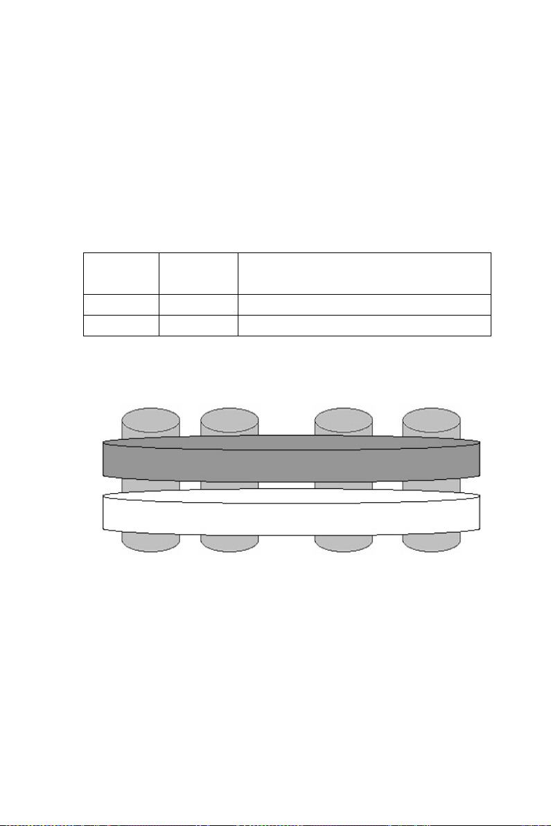
Each and every DNS-3200 is available with a SATA hot plug hard disk
when released from the factory plus 2 logically split areas. Data in the
split areas are available in the following tables and figures.
Note: Default layouts may vary depending on the num-
ber of hard disks.
Logical
RAID mode Size
Disk
1 1N 10 GB in disk 0, 1, 2 and 3
2 5 Remaining space in disk 0, 1, 2 and 3
Split Area of Operating System
logical Disk 1
RAID 1N
Data Split Area
logical Disk 2
RAID 5
Physical Disk 1 Physical Disk 2 Physical Disk 3 Physical Disk 4
DNS-3200 User’s Manual 4
Page 23
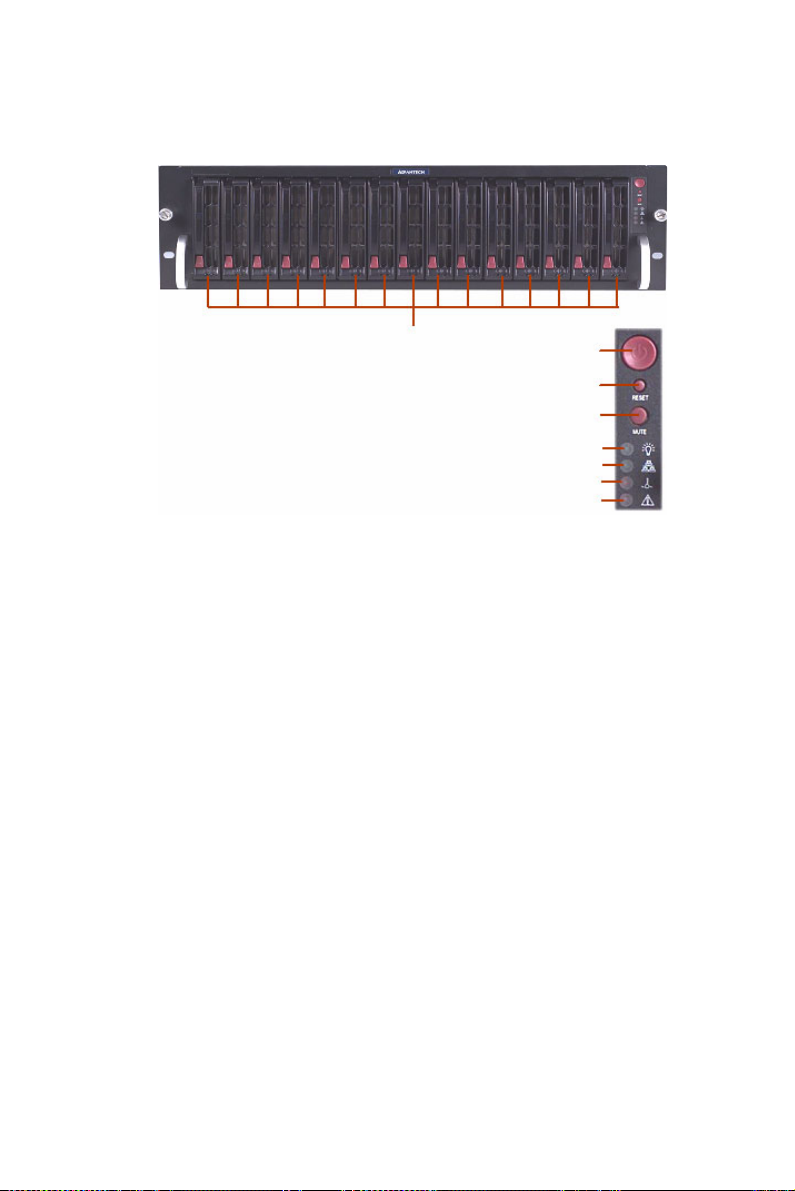
1.1.4 Product Appearance
The front panel is as shown below:
Figure 1.1: DNS-3200 Front panel
No Description
1 Power On/Off
2 Reset
3 Beeper silencer
4 Power indicator
5 Online active indicator
6 Temperature warning light
7 Voltage indicator
8
1
2
3
4
5
6
7
8 Independent hard disk indicators
5 Chapter 1
Page 24
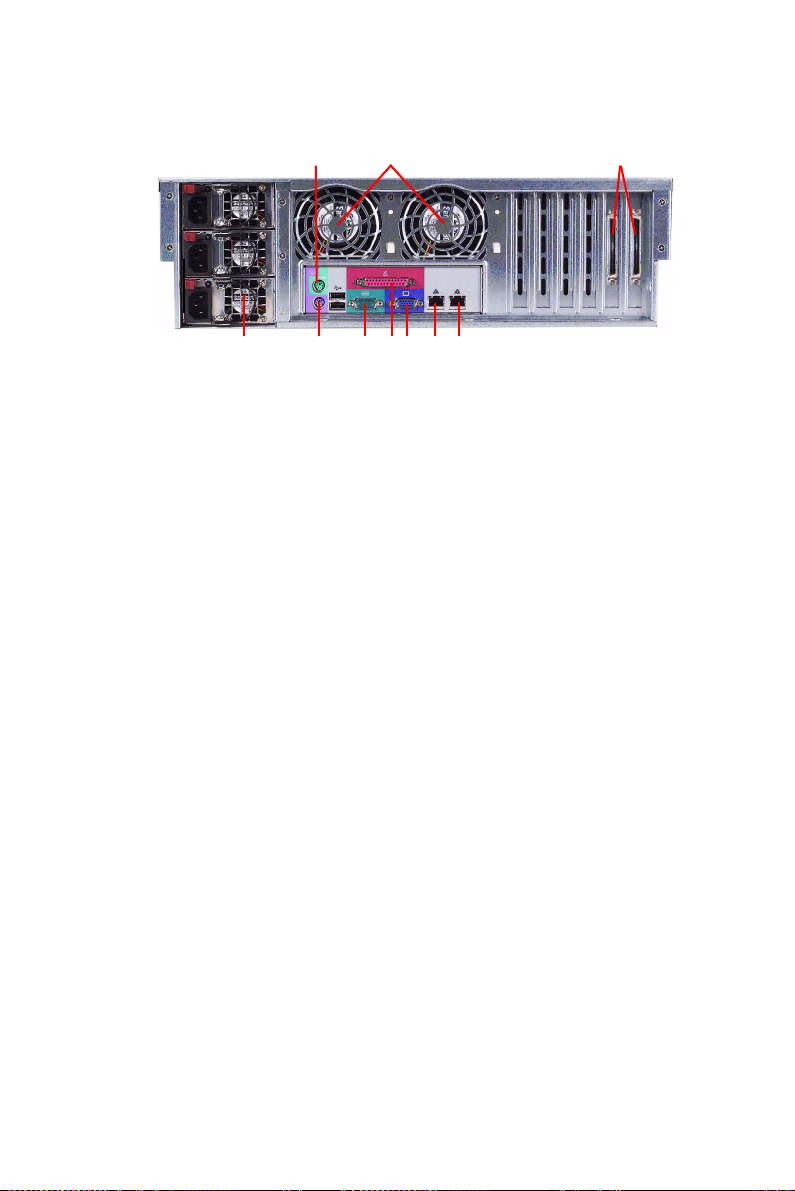
The rear panel is as shown below:
Figure 1.2: DNS-3200 Rear panel
No Description
1 Ultra320 SCSI external ports
2 Hot swap system fans
3 PS/2 mouse connector
4 RJ-45 Gigabit Ethernet port 1
5 RJ-45 Gigabit Ethernet port 2
123
5678910 4
6 Monitor output port
7 UPS port
8 PS/2 keyboard connector
9 Parallel port
10 Hot swap power module
DNS-3200 User’s Manual 6
Page 25
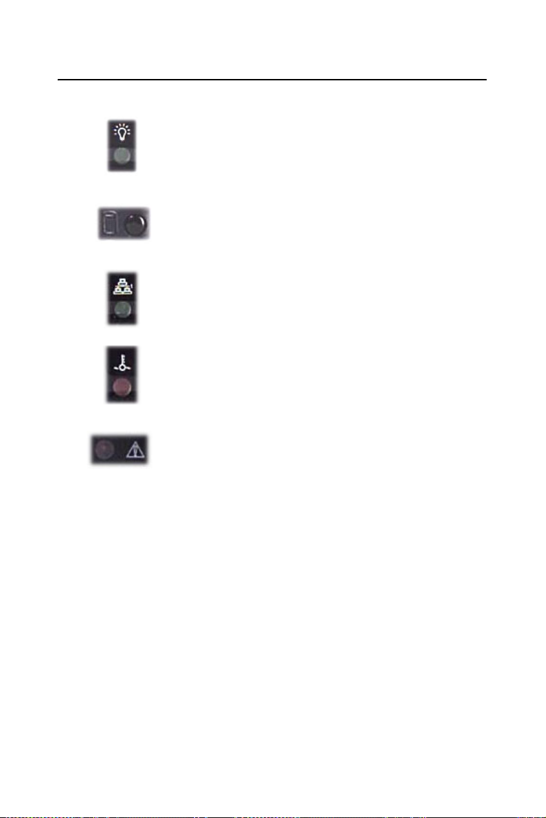
1.2 Panel Indicators
PWR: The power indicator turns green permanently
when pressing Power On/Off or when starting the unit.
HDD Active: Each and every hard disk comes with an
independent HDD Active indicator. When the hard disk is
being read or written to, the indicator turns green and
flashes.
Network State: This is the indicator that shows and state
of the network connection. When the port is communicating or transmitting, the indicator turns green and flashes.
Temperature Alarm: When the system develops abnormal temperatures, the LED indicator turns red.
Power Fail Alarm: When the system develops an abnormal power supply, the LED indicator turns red and the
system emits an alarm. Press the beep silencer to turn
the alarm off.
7 Chapter 1
Page 26

DNS-3200 User’s Manual 8
Page 27

2
2
CHAPTER
Chassis Description
and Installation
This section explains how to install the
DNS-3200 chassis.
This section includes:
• Chassis Description
• Chassis Installation
Page 28

Chapter 2 Chassis Description and
Installation
2.1 Chassis Description
Contents of the Accessory Kit:
The following items are included in the Accessory Kit:
DNS-3200 User’s Manual 10
Page 29

2.2 Chassis Installation
2.2.1 Important Safety Guidelines
Warning!: This product shall only be accessed, assembled
and serviced by technically qualified personnel or
technicians.
To avoid personal injury and property damage,
please read all the information provided in Chapter 1, and carefully follow all the Safety Guidelines listed before accessing or servicing the
DNS series or its components.
For your convenience, some safety steps are
also listed below.
Safety Steps
Before accessing the chassis:
1. Use a grounded wrist strap designed to prevent static discharge
when handling components.
2. Turn off all peripheral devices and turn off the power supply connected to the DNS series.
3. Unplug all power cords from the system or wall outlets.
4. Disconnect all the cables and label the cables for easy identification.
Removing the chassis covers:
After completing the above steps, you can remove the chassis covers and
install components and devices into the chassis as described in this chapter.
1. Unlock and remove the screws and fasteners to remove the cover or
components.
2. Save all the screws and fasteners for later use. (If necessary, label
these screws or fasteners for easy identification.)
3. Follow the instructions given in this chapter to remove the chassis
covers.
11 Chapter 2
Page 30
2.2.2 Tools Needed
1. Phillips screw driver
2. Antistatic strap (recommended)
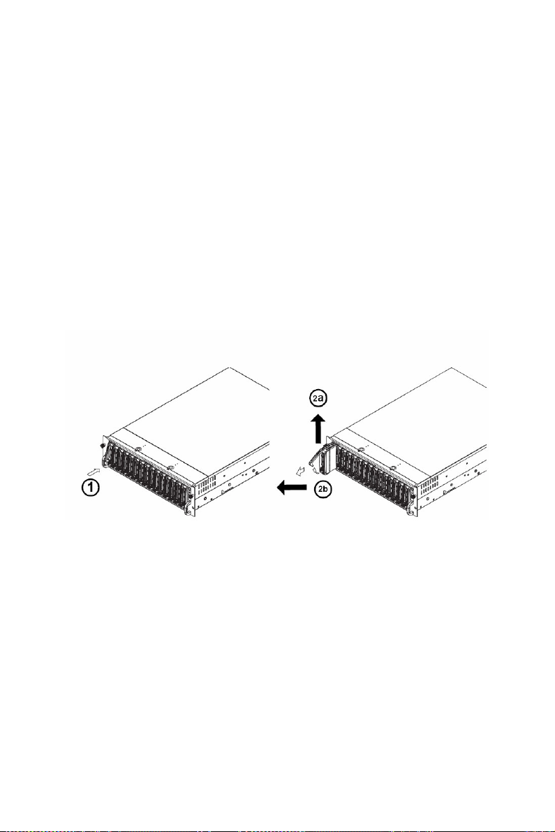
2.2.3 Accessing the SCA Drive Tray and Installing a HDD
To install the SCA drive into the chassis, you need to first remove the
SCA drive tray from the chassis.
Procedures
1. Press the release tab located on the drive tray door to release the
drive tray from its locked position as shown below.
2. Pull the drive tray door upward and then pull the SCA drive tray
out from the chassis.
3. Mount a hard drive in the drive tray and make sure that all the
screws are securely fastened.
DNS-3200 User’s Manual 12
Page 31

2.2.4 Accessing the 760W Power Supply
(*For Triple Redundant Power Supply- 3 x PWS-0050M)
Caution: Unplug the power cord before removing the
power supply.
Procedure
1. Locate the release tab on the left side of the power supply.
2. Push the release tab to the right to release the power supply from its
locked position as shown below.
13 Chapter 2
Page 32

3. Once the power supply module is released from its locked position,
remove it from the chassis.
DNS-3200 User’s Manual 14
Page 33

Please make sure the chassis covers and chassis rails are installed on the
chassis before you install the chassis into the rack.
Warning!: To avoid personal injury and property damage,
please carefully follow all the safety steps listed
below.
Before installing the Chassis rails:
1. Enclose the chassis with chassis covers.
2. Unplug the AC power cord(s).
3. Remove all external devices and connectors.
Procedure for Installing Chassis Rails
1. A pair of rail assemblies are included in the shipping package. For
each rail assembly, locate the inner rail and the outer rail.
2. Press the locking tab to release the inner rail from its locked position and pull out the inner rail from the rail assembly.
.
15 Chapter 2
Page 34

3. Locate the five rail hooks on each side of the chassis and locate the
five corresponding holes on each inner rail.
Note: The inner rails are to be attached to the chassis
and the outer rails are to be installed in the rack.
4. Align the end with the larger holes against the corresponding
hooks. Once all holes are aligned, push the holes toward their corresponding hooks until the rail is placed on the chassis.
5. Once the rail is placed on the chassis, pull the rail forward until the
rail hooks lock in the end with the smaller holes.
DNS-3200 User’s Manual 16
Page 35

6. Secure the rail to the chassis with a Type G screw (Refer to the figure given below). Repeat the above steps to install the other rail on
the chassis.
2.2.5 Rack Installation
After you have installed the inner rails on the chassis, you are ready to
install the outer rails of the rail assemblies in the rack.
Note: The rails are designed to fit in racks with a depth
of 28" to 33".
Procedure
1. In the package, locate the pair of front brackets (short) and rear
brackets (long). Please note that the brackets are marked with Up/
Front Arrows (front) and Up/Rear arrows (rear).
2. Secure the front (short) bracket (marked with the Up/Front arrows)
to the outer rail with two type G screws.
3. Locate the two hooks on the outer rail and attach the rear (long)
bracket to it by sliding the opening of the rear rail through the hook.
4. Measure the depth of your rack and adjust the length of the rails
accordingly.
17 Chapter 2
Page 36

5. Repeat the same steps to install the other outer rail on the chassis.
DNS-3200 User’s Manual 18
Page 37

6. Secure both outer rail assemblies to the rack with type H screws
and type I washers.
19 Chapter 2
Page 38

7. Once the rail assemblies are securely installed on the rack, slide the
DNS series into the assemblies as shown below.
Note: The DNS series may not slide into the rack
smoothly or easily when installed the first time.
Some adjustment to the slide assemblies might
be needed.
DNS-3200 User’s Manual 20
Page 39

8. Secure the DNS Series in the rack by tightening the screws on the
front sides as shown below.
21 Chapter 2
Page 40

DNS-3200 User’s Manual 22
Page 41

2
3
CHAPTER
Configuration
This section explains how to install the
DNS-3200 chassis.
This section includes:
• Configuration Settings
Page 42

Chapter 3 Configuration
3.1 Configuration Settings
Before starting DNS-3200 for the first time, it is necessary to have the
system undergo Initialization Setup, which includes setting the title, area,
language of the computer, manager’s password, network configuration as
well as activation of the system. After this, the user may proceed to use
DNS-3200. This section contains information on Initial Setup.
Note: Before turning the computer on for the first time,
be sure the hardware has been properly installed
and the network wires and power cord are connected properly.
3.1.1 Turning the system on for the first time
1. When turning the system on for the first time, it will enter into the
Initialization Setup screen (as shown below) and by pressing Next,
Initialization Setup starts.
DNS-3200 User’s Manual 24
Page 43

2. The END-User Authorization Agreement screen appears (as shown
below). Please read the agreement carefully before accepting the
agreement. Click Next to proceed.
25 Chapter 3
Page 44

3. The Regional and Language Options screen appears (as shown
below). Here the user may select Customize and Details to set location, language, language on display and key-in methods. Click
Next to proceed.
4. The Personalize Your Software screen then appears. Key in your
and your organization’s name. Click Next to proceed.
DNS-3200 User’s Manual 26
Page 45

5. Specify the computer’s name and password for the Administrator.
Type the Administrator’s password again in Confirm Password.
Click Next to proceed.
6. The Date and Time settings screen appears. Select the correct date
and time zone. Click Next to proceed.
27 Chapter 3
Page 46

7. The system will then install networking components. The system is
set for installation of TCP/IP Protocol. IP is set as DHCP. Click
Next to proceed.
8. The system will restart. You will need to key in the new manager
password for log-in.
After the login is completed, the system will automatically have the two
Gigabit cards of the DNS-3200 set to load balancing mode (as shown
below), where DNS-3200 has only one IP for access and the DNS-3200
will automatically assign the network flow onto the 2 network ports.
Besides, it is available with failover function, which means that when one
network port fails, the other one will be switched on automatically, just to
maintain the online communication.
DNS-3200 User’s Manual 28
Page 47

Note: The load balancing mode requires the two net-
work ports to be connected to one hub for normal
operation. If the user chooses not to operate
under load balancing mode, or an alternative
mode is required, please see “Network Configuration Setting”.
9. After setting load balancing mode, it is necessary to restart the system. Microsoft requires starting WSS2003 first to allow the system
to become available.
3.1.2 WSS2003 Activation
Microsoft Windows Storage Server 2003 must undergo its activation procedure before you start using it. The activation procedure is possible via
the internet or by phone. In this chapter, the procedure for activating
WSS2003 via the Internet is described. Before starting the procedure,
make sure the system is available for connection to the internet.
Note: Microsoft makes the system available for use for
30 days without activating it. If the user fails to
activate WSS2003 within 30 days, on the 31st
day, the user will not be able to log in and then
must activate to continue use.
29 Chapter 3
Page 48

1. In Start, All Programs, select Activate Windows for Initialization
Setup. (See figure below)
DNS-3200 User’s Manual 30
Page 49

2. Then select “Yes, let’s activate Windows over the Internet now” (as
shown below) and click Next to proceed.
31 Chapter 3
Page 50

3. Then select “No, I don’t want to register now”, let’s just activate
Windows (as shown below) and click Next to proceed.
4. The system will check the online status of the internet connection.
If the user can log on via internet successfully, the screen requesting the user to key in the Product Key (as shown below) will
appear. When the DNS series is released from the factory, the software authorization sticker for the WSS2003 operating system is
pasted on the unit. After keying in the Product Key given on the
sticker, press Retry.
DNS-3200 User’s Manual 32
Page 51

5. After starting the system successfully, a screen appears indicating
the system has been successfully started. The initial setup for the
DNS-3200 is complete and the user may proceed with other settings for the unit.
6. For remote management of the DNS-3200 via the internet, please
refer to the WSS_2003 user Guide available on the enclosed CD.
Note: If the system is unable to log onto the Internet for
Initialization Setup, browse to the following website for local telephone numbers:
http://www.microsoft.com/licensing/resources/
vol/numbers.nspx
33 Chapter 3
Page 52
3.1.3 Network configuration setting
When preset, the DNS-3200 can have the two built-in ethernet ports set as
Network Load Balancing in Team Mode, which provides both network
flow balancing and fault tolerance functions. To change the team mode,
use Intel®PROSet for management of DNS-3200 Team Configuration.
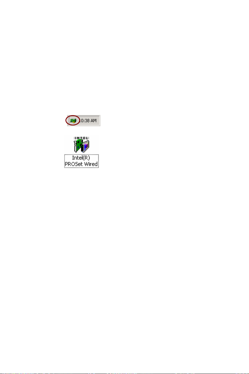
Intel PROSet
Intel PROSet is a program for advanced network configurations that
allows the user to test network interface cards while setting standard and
advanced functions. For the DNS-3200, there are several ways for the
user to start the Intel PROSet program:
Task bar: Double-click to start the program.
Console:
PROSet’s main window is shown below. To set advanced parameters,
select the required interface cards from the window on the left and press
the Advanced tab for associated settings. To change to online mode,
select “Team #0 - Adaptive Load Balancing” from the window to the left
by right-clicking the mouse. Then proceed with removal of Team Mode
or change Team Mode as required. After setting, press OK for the change
to be effective.
DNS-3200 User’s Manual 34
Page 53

Note: When changing Team Mode, online communica-
tions may experience temporary interruption.
Test Online Active
PROSet is able to test interface cards by checking the interface card hardware, cables or team for failures.
1. Start Intel PROSet.
2. Select the network interface card to test.
3. Press the Diagnostics tab once for the list of items to test.
4. Press Run Tests and select the items you want to test. Error information appears if any of the tests are failed.
5. Repeat Steps 2-4 to test each network interface card installed in the
computer.
35 Chapter 3
Page 54

Team M ode
Details of the functions and configurations required for each online mode
provided by the DNS-3200 are given below.
Adapter Fault Tolerance (AFT)
Function: AFT provides automated residue to the network interface card
as a fault tolerance. From the two network ports connected to the switch
or hub at the same time, one is the primary network for normal team, and
the other is the backup and is usually not in the “On” state. If the primary
online adapter card develops a problem, the backup network will start and
take over the team.
Network configuration:
1. The network port must be connected to the same network switch.
2. The switch must have the Spanning Tree Protocol (STP) in the
“Off” state.
3. All switches are available for support.
DNS-3200 User’s Manual 36
Page 55

Swap Fault Tolerance (SFT)
Function: SFT provides automated residue to the network interface card
as a fault tolerance. With the two network ports connected to different
switches, one is the primary network for normal team and the other is the
backup and is usually not in the “On” state. If the primary online develops
problems, the backup network will start and take over the team.
Network configuration:
1. Each network port must be connected to a different network switch.
2. The switch must have the Spanning Tree Protocol (STP) in “On”
state.
Adaptive Load Balancing (ALB)
Function: ALB provides load balancing and fault tolerance to the net-
work flow and uses the software to analyze the transmission load on each
interface card. For the two network ports sharing the load balancing of the
transmission load and received flow load balancing of the IP protocol, if
one team develops problems, the other team will take over the task.
Network configuration:
1. The network ports must be connected to the same network switch.
2. All switches must be able to support ALB.
Note: ALB does not balance non-routable communica-
tion protocols, such as NetBEUI and some other
IPX* flows.
37 Chapter 3
Page 56

Static Link Aggregation
Function: Static Link Aggregation provides network links for increased
transmission and receiving flow as well as negative balancing and fault
tolerance. The two network ports share all network flows, when one team
develops problems, the other one takes over all tasks.
Network configuration:
1. The network ports must be connected to the same network switch.
2. All network ports must be online at the same speed.
3. Use only network switches capable of Link Aggregation:
• Use Cisco FEC or GEC network switches with the PAgP proto-
col.
• Intel network switches
• All network switches supporting static 802.3ad.
Dynamic Link Aggregation
Function: Dynamic Link Aggregation provides network links for
increased bandwidth as well as negative balancing and fault tolerance.
Two network ports share all network flows, when one team develops a
problem, the other one takes over all tasks.
Network configuration:
1. The network ports must be connected to the same network switch.
2. All network ports must be online at different speeds.
3. The online switches must be fully compatible with the IEEE
802.3ad standard.
Note: For full functions and details on the use of
PROSet, please refer to User Instructions on
PROSet.
DNS-3200 User’s Manual 38
Page 57

2
4
CHAPTER
Managing Arrays and
Disks
This section gives information about
Arrays and Disks.
This sections includes:
• RAID Minimum Disk Requirements
• Arrays and Disk States
• Tasks and Spares
Page 58

Chapter 4 Managing Arrays and Disks
4.1 RAID Minimum Disk Requirements
The following table lists the minimum and maximum number of disks for
each RAID level.
Table 4.1: Min and Max Disks for RAID levels
RAID Level Minimum Number of
Disks
Volume 1 32
RAID0 2 32
RAID1 2 2
RAID1n 3 16
RAID10 4 32
RAID10n 6 32
RAID5 3 16
RAID50 6 32
Maximum Number of
Disks
4.2 Understanding Array and Disk States
The controller uses states to report the status of arrays and disks. To
ensure the health of your data, it is important to understand what each
array and disk state means as well as what causes them to change.
Array States
Within the management applications, an array is a logical device that can
exist in one of three states: NORMAL, CRITICAL, or OFFLINE. In
RAIDConsole, these states are shown in the Array List area in a column
named State. Within the bcadm program, these states also shown in the
column named State. The states are defined as follows:
Whether an array is marked as CRITICAL or OFFLINE depends on the
type of array and how many disks within the array have failed. Note the
following changes in state:
DNS-3200 User’s Manual 40
Page 59

1. NORMAL The NORMAL state is displayed when everything is
functioning correctly.
2. CRITICAL The CRITICAL state is displayed when the array is no
longer redundant (fault tolerant) because of one or more disk failures. Arrays can still be read and written to, but the data is no
longer protected should another drive fail.
3. OFFLINE The OFFLINE state is displayed when arrays cannot be
read or written to because of one or more disk failures.
• For RAID1 and RAID5 (redundant arrays), the CRITICAL state is dis-
played when a single disk fails.
• For RAID1n, RAID10, RAID10n, or RAID50 (array types with multi-
ple redundancies), the CRITICAL state is displayed if a single disk
fails in any one of those sets.
• For Volume and RAID0, the OFFLINE state is displayed when a single
disk fails.
• For RAID1 and RAID5 (redundant arrays), the OFFLINE state is dis-
played when two or more disks fail.
• For RAID1n, RAID10, RAID10n (array types with multiple redundan-
cies), the OFFLINE state is displayed if all disks in a set fail.
• For RAID50 (an array type with multiple redundancies), the OFFLINE
state is displayed if two or more disks fail within the same set. For
example, RAID50 is a stripe of RAID5 sets. If a RAID50 set contains
three RAID5 sets, each RAID5 set can have up to one disk failure and
the RAID50 array state shows as CRITICAL. If a fourth disk fails, the
state of the RAID50 array changes to OFFLINE. If two drives fail on
one of the RAID5 sets, the state of the RAID50 array changes to
OFFLINE.
More than one array can be created using the same set of disks. If you disconnect a disk that belongs to more than one array, only the arrays that try
to access the disk and receive I/O errors report the failure. For example:
you have two arrays, both RAID5 sets, and both use disk 4. If a system
being used by array 1 receives an I/O error when trying to communicate
with disk 4, the state of array 1 will change to CRITICAL. However, the
state of array 2 using disk 4 will not change to CRITICAL until an I/O
error is reported. If systems using array 1 are not communicating with the
failed disk, the state of array 1 still displays as NORMAL. If you perform
41 Chapter 4
Page 60

a rescan of all channels after disconnecting a disk, the state of every array
using the missing disk changes from NORMAL to either the CRITICAL
or OFFLINE, depending on the array type.
Disk States
Within the management applications, a disk can be part of one or more
arrays and can exist in one of three states: NORMAL, FAILED, or
UNKNOWN. In RAIDConsole, these states are displayed in the Disk
List area in a column named State. Within the bcadm program, these
states are also displayed in a column named State. The states are defined
as follows:
• NORMAL The NORMAL state is displayed when the disk is con-
nected, functioning correctly, and the controller can communicate with
it.
• FAILED The FAILED state is displayed when the controller can rec-
ognize the disk, but cannot read or write to it.
• UNKNOWN The UNKNOWN state is displayed when the disk is new
and has not been initialized, or is in a format unrecognizable by the
controller.
If a disk fails, its state in the Disk List is displayed as FAILED. However,
if the system tries to communicate with a disk that has been physically
disconnected, the disk shows as FAILED in the Array List window but
still appears in the Disk List as NORMAL until a rescan is performed.
After you have rescanned the SATA channels for information, the disconnected disk disappears from the Disk List.
DNS-3200 User’s Manual 42
Page 61

Rescanning for Changes in State
When using the bcadm program, the disk information that displays when
you run a query command is always current. In the RAIDConsole application, however, the information displayed in the Disk List area is the
state of the disks when they were last scanned. If you have not performed
a rescan, the information being displayed is the state of the disks at boot
time.
Every time you connect or disconnect a disk while online, a message asking if you want to perform a rescan (of all SATA channels) appears. If you
choose Ye s , the information in both the Array List and the Disk List is
updated. However, this view may show arrays as being in a CRITICAL or
OFFLINE state if not all disks have been installed or removed.
Although it is highly recommend that you shut down the system before
you add or remove disks, you may also be able to add or remove disks
while online if your system supports that feature. Because of this feature,
RAIDConsole does not automatically perform a rescan when it detects
that a disk has been added or removed. For example, if you want to hotswap a RAID5 set with six disks into a new system, do not perform a rescan until all six disks have been connected. Otherwise, any arrays associated with the disks that are not yet connected change state to either
CRITICAL or OFFLINE. If the state of your RAID5 set changes to
OFFLINE, you will lose your data. This feature can also result in the state
of a disk being reported differently in the Array View and the Disk List.
A disk within an array can have a state of FAILED in the Array tree view
while at the same time it can show a state of NORMAL in the Disk List.
43 Chapter 4
Page 62

4.3 Starting and Stopping Tasks
Tasks are started when you:
• Create a redundant array.
• Transform an array.
• Restore an array.
• Check for consistency on redundant arrays.
• Verify a consistency bitmap (check_bitmap) on a redundant array.
The only type of task that you can stop without deleting the array is a consistency check (CHECK).
The following types of tasks can be displayed for each array:
• TRANSFORM The TRANSFORM task is displayed while an array is
being transformed.
• CREATE The CREATE task is displayed while an array is being cre-
ated.
• CHECK The CHECK task is for redundant type arrays only. This task
is displayed while verifying that the parity (RAID5) or mirror drive
consistency is correct.
• RESTORE The RESTORE task is displayed while an array is being
restored.
• CHECK_BITMAP The CHECK_BITMAP task is displayed while
verifying that the parity on a RAID5 set, or the mirror halves on a
RAID1/10 set, are consistent. This action is performed automatically if
your system crashes.
• NOT_ACTIVE The NOT_ACTIVE task is displayed when no other
tasks are being performed.
DNS-3200 User’s Manual 44
Page 63

Note: When a task is in progress and the system is
shut down, the RAID driver may hang under certain circumstances. This may occur if arrays exist
and a task is in progress, but a drive letter has
not been assigned AND an OS partition has not
been created on the array. Because neither a
drive letter nor partition has been assigned, the
OS doesn’t notify the RAID driver that the system
is shutting down. If this condition occurs, the system can be reset, the OS will start, and the RAID
process will also restart.
4.4 Working with Spares
4.4.1 About Sparing Options
The DNS-3200 Series RAID controller supports three sparing options:
• Distributed A patent-pending sparing option comprised of reserved
space on each disk in an array
• Dedicated A spare disk assigned to a specific, redundant array
• Global A spare disk that is shared by multiple arrays
Spares are restored in the following order:
• Dedicated
• Distributed
• Global
45 Chapter 4
Page 64

Notes: 1. An array is marked critical or offline if a disk
returns failure to an I/O request, or if the SATA or
power cable is disconnected.
2. You can assign one or more spares to a
redundant array type.
3. Spare assignments do not apply to non-redundant array types. To protect this data, you must
first transform the array to a redundant array type
(see “Transforming Arrays”). You can then assign
spares.
4.4.2 Using Distributed Sparing
The distributed sparing feature reserves space on each drive in an array.
This space is used when the data from a failed drive is being regenerated
during a restore task. Whereas other methods of sparing (such as dedicated spares) provide the same level of protection, distributed sparing
provides better performance because all drives are active in an array and
are not sitting idle, as is the case with dedicated spares. Another advantage of distributed spares is that because all drives are active, a drive cannot fail and go unnoticed, as is the case with dedicated or global spares.
This is because with distributed sparing, each array has its own dedicated
fail-over spaces.
This averts the potential problem of having insufficient space to start a
failover on the single disk that has been assigned as a spare.
A distributed spare is assigned at the time an array is created or transformed. Distributed spares are valid only for RAID5 (four or more
drives), RAID50 (four or more drives per RAID5 set), and RAID10 and
RAID10n (six or more drives).
This spare type is the most protective because space is allocated when the
array is created. Like a dedicated spare, this spare type is assigned to a
specific array. If you initially created an array without a distributed spare,
you must transform the array to add a distributed spare. This is because a
distributed spare can be assigned only when an array is being created or
transformed.
DNS-3200 User’s Manual 46
Page 65

Notes: 1. If there is insufficient unused space on the
disks in an array, you cannot add a distributed
spare without adding an additional disk and
transforming to an array with distributed sparing
enabled. The distributed spare option uses the
equivalent storage of one of the disks in the
array. For example: the total capacity of six
drives is being used in a RAID5 array, and you
have enabled distributed sparing, the capacity of
the array is the same as a four-drive RAID0. The
capacity of one disk is lost to the RAID5 parity
data, and the capacity of another disk is lost to
the distributed sparing option.
2. See “About Sparing Options”.
To add a distributed spare while creating an array:
1. On the Array menu, click Create.
2. Configure the array.
3. In the Distributed Spare field, click Enabled.
47 Chapter 4
Page 66

To add a distributed spare while transforming an array:
1. On the Array menu, click Transform.
2. Configure the new array.
3. In the Distributed Spare field, click Enabled.
To remove a distributed spare:
1. On the Array menu, click Transform.
2. Configure the new array.
3. In the Distributed Spare field, click Disabled.
4.4.3 Using Dedicated Sparing
A dedicated spare is a disk that you assign as an alternate disk for a specific array. Should a disk fail in that array, the alternate disk is used to
replace the failed disk and the array is rebuilt. A dedicated spare can be
assigned to any redundant array type, and up to four spares can be
assigned to an array.
DNS-3200 User’s Manual 48
Page 67

Notes: 1. Assigning a dedicated spare does not reserve
space on that drive. Therefore, an automatic
restore is not guaranteed if a disk fails. If a disk
does fail, you must make room on the disk for the
fail-over to complete, or you must assign a different disk with enough room. If a dedicated spare
is assigned and a drive fails, the restore process
starts automatically if there is enough space
available on the dedicated spare.
2. You cannot assign a dedicated spare while a
task is running on the array.
3. When you assign a dedicated spare either
while creating or transforming an array, the first
drive you select to create the array is assigned
by default as the dedicated spare.
4. When you add a dedicated spare after the
array has been created, you can select which
disk to use as the spare.
5. For more information see “About Sparing
Options”.
49 Chapter 4
Page 68

4.4.4 Using Global Sparing
A global spare is a disk that you assign as an alternate disk for multiple
arrays instead of associating it with just one. Many arrays can be restored
using the global spare disk as long as it is not already part of the array and
it has enough space available. Unlike a dedicated spare, this type of spare
can be assigned at anytime, even while tasks are running on arrays.
Notes: 1. Assigning a disk for use as a global spare
does not reserve space on that disk. Therefore,
an automatic restore is not guaranteed if a drive
fails. If there is not enough disk space on the global spare, you must either make room for the failover to complete or assign a different disk with
enough room as the spare. However, if there is
enough space available on the global spare and
a drive failure occurs, the restore process starts
automatically.
2. For more information see “About Sparing
Options”
DNS-3200 User’s Manual 50
Page 69

2
5
CHAPTER
BIOS Configuration
Utility
This section explains when and how to
use the BIOS Configuration Utility.
This sections includes:
• When to Use BIOS Utility
• BIOS Utility Color Codes
• Initializing Disks from the BIOS
• Creating Arrays from the BIOS
• Deleting Arrays from the BIOS
• Swapping Arrays from the BIOS
• Hiding or Unhiding Arrays from the
BIOS
• Viewing Disk Details from the BIOS
• Viewing Array Details from the
BIOS
• Rescanning All Channels from the
BIOS
• Changing Controller Options from
the BIOS
• Continue Booting from the BIOS
Page 70

Chapter 5 Using the BIOS Configuration
Utility
5.1 When to Use the BIOS Configuration Utility
The firmware component of the installation kit includes the BIOS Configuration Utility. You must use this utility to:
• Create the boot array: If you are not booting off of the array, you do
not need to use this utility to create an array, although you can. You can
create a non-bootable array in the RAIDConsole management application.
• Swap in a copy of the boot array: In RAIDConsole, you can make a
copy of your boot array by mirroring and then splitting the array. By
default it is hidden from the operating system. If you were to lose the
boot array, you can use the BIOS Configuration utility to Unhide the
copy and swap it into the first position in the Arrays list.
• Initialize a new disk: When you are adding a new disk you can initialize it from the BIOS.
Notes: 1. The first device in the Arrays list is the boota-
ble array. You can only boot from the first device
in the list.
2. Until the BIOS loads, the LEDs are not indicative of disk connectivity.
To enter the BIOS Configuration Utility
When booting the system, press CTRL+R when the BIOS banner is displayed. You have up to three seconds to enter the BIOS using this key
combination.
DNS-3200 User’s Manual 52
Page 71

5.2 Color Codes for the BIOS Array Config Utility
The following color codes are used to indicate the type or status of information displayed on the screen.
• White text Available option or informational text
• Yellow highlighting Current option on which you may choose to
take action
• Green text Item has been selected
• Light blue text Item is not available for selection
• Yellow text Informational text, describes an option
• Magenta text Spare options and boot options
• Red text Failed drive or other warning to user. For
example, informational text may be red if the
option is not available.
5.3 Initializing Disks from the BIOS
Before using new disks they must be initialized and at least the boot array
must be created using the RAIDCore BIOS Array Configuration Utility.
Initialization writes the configuration information to disk. The BIOS utility can be used to create and manage arrays so that an operating system
can be installed on an array. The system is then booted from this array.
Notes: 1. When you highlight a disk from the Disk list,
the LEDs on the controller or a properly cabled
disk enclosure light up to identify that disk.
2. If you want to boot from another controller
within your system, you may need to disable
INT13 in the BIOS. See “Changing Controller
Options from the BIOS”.
3. For more information see “Color Codes for the
BIOS Array Config Utility” in 5.2.
53 Chapter 5
Page 72

To initialize disks from the BIOS:
1. Turn on your computer to start booting.
2. When prompted, type <CTRL-R> to access the RAID BIOS Array
Configuration Utility. The RAID Array Configuration menu is
displayed (see “Color Codes for the BIOS Array Config Utility” in
5.2.
3. Use the arrow keys to select Initialize Disk(s) from the Main
menu.
4. Press Enter.
5. Use the arrow keys to highlight a disk, and then press the Insert
key to select the disk or choose all selectable disks by pressing A.
Note: You can select multiple disks; there is no need to
initialize one disk at a time.
5.4 Creating Arrays from the BIOS
After your disks are initialized, you can create arrays. You can create a
maximum of eight arrays from the BIOS. See “Understanding Arrays” if
you have not yet decided what type of arrays you need.
DNS-3200 User’s Manual 54
Page 73

Notes: 1. In some circumstances, more than eight
arrays are possible and may appear to function
properly, but are not supported by Broadcom.
2. For redundant arrays, the creation process
does not complete until after the operating system and controller drivers have been installed
and you have booted into the operating system
context. However, the arrays are immediately
available to use for either a boot or data array.
3. Array numbers are valid only for a given boot,
and may be different in the BIOS and drivers. If a
permanent label is required, use the labeling feature.
4. When you highlight a disk from the Disk list,
the LEDs on the controller or a properly cabled
disk enclosure light up to identify that disk.
5. At any point in the following procedure, you
can return to a prior screen by pressing ESC.
6. See see “Color Codes for the BIOS Array Config Utility” in 5.2.
To create an array:
1. From the main menu of the Array Configuration screen, select Cre-
ate Array using the arrow keys, and then press Enter.
2. Select the disks on which to create the array by doing the follow-
ing:
a. Highlight the disk using the arrow keys.
b. For each disk, press the Insert key to select the disk. You can
insert the disks in any order.
c. After selecting the disks to be included in the array, press Enter.
3. In the User Input area, select an array type with the arrow keys,
and then press Enter. Only array types that can be created with the
selected disks are available.
4. If spares are applicable:
55 Chapter 5
Page 74

a. In the User Input area, highlight a spare type using the arrow
keys.
b. If applicable, in the Disks area, highlight the disk(s) to use as a
spare and press Insert to select them.
c. Press Enter to add the spare disk(s).
5. To select an array size, do one of the following:
6. Use the Page Up/Page Down keys or the arrow keys to select a
size, and then press Enter.
Note: By default all available space up to 2.199 TB is
selected.
Or do the following:
To create an array that is greater than 2.199 TB (the maximum
allowed by some operating systems):
Note: The Windows operating system does not support
arrays larger than 2 TB.
1. Press PAGE UP or the up arrow to increase the array size. You are
asked if you want to limit the size of the array to the 2 TB maximum.
2. Press ESC to create a larger array.
3. Press PAGE UP or the up arrow until you have reached either the
desired size or the maximum available.
4. Press Enter.
5. Select a caching mode using the arrow keys, and then press Enter.
6. Press C to continue the array creation process.
DNS-3200 User’s Manual 56
Page 75

Note: For installations of SuSE Linux, a popup appears
that says, “A new device was found, do you want
to configure it?” If you do not want to see this
popup when you create arrays, you can check
the “Do not notify me” checkbox.
7. The array is marked Ready for use, and the text at the top of Array
Configuration returns to a description of the menu items.
8. When you are finished creating arrays, resume the boot process:
a. From the Main menu, highlight Continue to Boot.
b. Press Enter. No reboot is required.
Figure 5.1: Create an array
In the example above, a 4-drive RAID5 array has been configured.
57 Chapter 5
Page 76

5.5 Deleting Arrays from the BIOS
This option allows you to delete arrays.
Caution!: Deleting an array permanently destroys all data
that was on the array. You will not be able to
undo this action and all data will be lost.
To Delete an Array:
1. Highlight Delete Array(s) from the Main menu and press Enter.
2. Do one of the following:
a. Highlight each array to delete and press Insert to select it.
Or
b. Type A to select all arrays for deletion.
3. Press Enter.
4. Press C to continue.
5.6 Swapping Arrays from the BIOS
Using the Swap Two Arrays option, you can reorder arrays.
Notes: 1. If you create more than one array, you can
install the operating system to any of them. However, a small amount of boot information is
always written to a disk in the first array on your
array list regardless of which array you install the
operating system on. If anything happens to that
disk in Array 1, you will not be able to boot.
Broadcom recommends installing on a redundant
array type — such as RAID1 or RAID5 — and
then swapping that array into the first position if it
is not already Array 1.
2. This swap feature is only available from the
BIOS.
DNS-3200 User’s Manual 58
Page 77

To swap arrays:
1. Highlight Swap Two Arrays in the Main menu, and then press
Enter.
2. Use the arrow keys to highlight an array, and then press Insert to
select it.
3. Use the arrow keys to highlight another array, and then press Insert
to select it.
4. Press Enter to swap the arrays.
Figure 5.2: Swap arrays
In this example, the RAID10 array was the first array created. However,
to boot from the RAID5 array, the arrays were swapped so that the
RAID5 array is the first device listed.
59 Chapter 5
Page 78

5.7 Hiding or Unhiding Arrays from the BIOS
The Hide/Unhide array option allows you to hide or Unhide an array or
arrays from the operating system. If an array is hidden it will not be visible through INT13 or to the operating system when booted. This is a useful feature for hiding hot backups of the system.
Note: You cannot hide a legacy array from the BIOS.
You can hide a legacy array from the operating
system (using RAIDConsole), if you have not
booted off the legacy array and another non-legacy disk is attached to the controller.
To hide or Unhide an array:
1. Select the Hide/Unhide option.
2. Use the arrow keys to highlight the array to be hidden or unhidden.
3. Press the Insert to select an array.
4. Press Enter to commit the selection.
The hidden array turns blue in the BIOS Configuration Utility and the
status of the array displays as Hidden.
DNS-3200 User’s Manual 60
Page 79

5.8 Viewing Disk Details from the BIOS
This option allows you to view details about the disk. When you highlight
a disk from the Disk list, the LEDs on the controller or a properly cabled
disk enclosure light up to identify that disk.
Note: Nothing can be changed from this menu option. It
is for information only.
To view disk details:
1. From the Main menu, select View Disk Details.
2. Use the arrow keys to choose a disk.
The details of the disk are displayed in the Information field across the
top, and include the following data:
• Disk Number
• Controller Number
• Channel Number
• Disk Size
• New/Legacy/Empty/InArray
• Free Space
• Disk Model Number
61 Chapter 5
Page 80

5.9 Viewing Array Details from the BIOS
This option allows you to look at the details of the array. Nothing can be
changed from this menu option. It is for information only.
To view array details:
1. From the Main menu, select View Array Details.
2. Use the arrow keys to choose an array.
The full details of the array are displayed in both the Information field
across the top, and include the following data:
• Array Number
• Type
• Size
• State
• Name
• Cache setting
• DOS size
Note: The Disks list shows the disks in the array as
selected (green).
5.10 Rescanning All Channels from the BIOS
This option allows you to rescan all channels to detect new or removed
disks and arrays.
To perform a rescan, select Rescan All Channels from the Main menu.
The activity indicator in the Information field spins while the disks are
being polled.
DNS-3200 User’s Manual 62
Page 81

5.11 Changing Controller Options from the BIOS
Selecting Controller Options allows you to configure whether arrays
may be bootable, as well as other aspects of the boot process. The default
is to configure an array so that an operating system can boot from the
RAID. If an error occurs, an error message is displayed. However, you
may be booting from the motherboard IDE or another SCSI device in
your system. If this is the case, you may not want to install INT13 (without INT13, DOS cannot see the array).
Note: If you configure Boot Mode to install INT13 and
to never display an error message, you will not
know during the boot process if an array is
degraded or if other problems have occurred.
This menu also sets whether you want the boot process to pause when an
error occurs. When the Pause feature is enabled and an array goes critical
or offline, or there is a controller configuration error, the boot process
stops and you must press Enter to continue booting. This gives you time
to view the error message on the screen. If the Pause feature is disabled,
the error message is displayed briefly, but the system continues to boot.
To select a boot option:
1. From the Main menu, select Controller Options. The Controller
Options area is displayed in the BIOS Array Configuration Utility window as shown below. The current settings display in
magenta text above the white selectable options.
63 Chapter 5
Page 82

Figure 5.3: Change controller options
2. Use the arrow keys to select a boot option.
Note: By default, all options are turned on. Broadcom
recommends that you leave them enabled.
3. Do one of the following:
a. If you do not want to boot from an array, highlight Toggle INT13
Installation using the arrow keys, and then press Enter to
change the setting to Disabled. (We recommend disabling INT13
only if you want to boot from another device, and leave the rest
of the options enabled.)
Or
b. To turn off warnings due to critical arrays when booting, high-
light Toggle Pause if Critical, and then press Enter to change
the setting to Disabled.
Or
c. To turn off warnings due to offline arrays when booting, high-
light Toggle Pause if Offline, and then press Enter to change
the setting to Disabled.
DNS-3200 User’s Manual 64
Page 83

Or
d. To turn off warnings due to controller configuration errors when
booting, highlight Toggle Pause if Error, and then press Enter
to change the setting to Disabled.
5.12 Continue Booting from the BIOS
After you have created arrays, you can continue booting the system from
the point where the RAID BIOS was entered. To resume the boot, highlight Continue to Boot in the Main menu, and then press Enter. No
reboot is required.
65 Chapter 5
Page 84

DNS-3200 User’s Manual 66
Page 85

2
6
CHAPTER
RAID Console Operations
This section explains the RAID Console.
This section includes:
• RAID Console Management
Page 86

Chapter 6 RAID Console Operations
6.1 RAID Console Management
For the DNS-3200, RAID management is achieved using the RAID console, of which a brief description on the main functions is given in this
chapter. For detailed functions and use of the RAID console, please refer
to the RAID Management User Guide in the CD available with this unit.
RAID Console
RAID console can be started from the icon on the screen. When
you start for the first time, you will be asked whether to set or not to set
the manager password for RAID console.
DNS-3200 User’s Manual 68
Page 87

Notes: 1. The password must consist of at least 6 char-
acters.
2. Passwords are case sensitive.
3. Do remember the password and store in a
safe place. If you forget it, you will not be allowed
to access the RAID Console.
4. You are given four opportunities to key in the
correct password. After the 4th attempt, the program will close and you have to restart.
After a successful setting of the password, the user is allowed into the primary screen of the RAID Console, where there are four sections (as
shown below), which are described as follows:
RAID list
Disk State Area
RAID State Area
System I/O State
69 Chapter 6
Page 88

Disk State Area: Available with state information on each disk, including:
• Ctrl Chan: Shows which RAID controller channel the disk is connected to.
• State: Disk state, which could be Normal, Failed and Unknown.
1.Normal: Disk online and in normal operation.
2.Failed: RAID controller identifies the disk, but can not read it or
write to it.
3.Unknown: New disk or not initialized by RAID controller or
freshly formatted.
• Type: Type of disk located on the RAID controller (RC_DISK,
RC_Legacy, or NEW).
• Capacity: Capacity of the disk.
• Free Space: Space available on the disk.
• Largest Free: Continuous free space segment available on the disk.
• GS: Indicating whether the disk has been designated as a Global Spare.
• Model Number: Model number of the disk.
Array State Area: Available with information on each and every RAID
corresponding to each logical disk, including:
• Device: No. of disk RAID
• O.S. Name: Title designated by the operating system to the array. If the
array is in a hidden state, it shows Hidden; if it is off line, it shows “??”
• Partition: Number of the corresponding disks of the operating system
in the array.
• Array Name: Name given to the array.
• Type: Type of the array.
• Tot a l Cap a cit y : Space available in the array.
• State: The state before the array, which comes in Normal, Critical and
Offline.
1.Normal: Array in normal operation.
2.Critical: One or more disk failures make array fault tolerance not
available, yet the system has normal access to the array.
DNS-3200 User’s Manual 70
Page 89

3.Offline: One or more disk failures force the array to go offline, so
the system cannot access the array.
• Ta sk : Shows the RAID tasks being executed (Transform, Check,
Check_Bitmap, Not active, Create, and Restore).
• Priority: If any task is being executed, the priority of the task is shown.
• Cache: Cache mode of the array in NC = No Cache, R = Read Cache,
W = Write Back Cache and RW = Read/Write Cache.
• Dst Spare: Showing whether the array is available with distributed
spare.
• Ded Spare: Showing whether the array is available with dedicated
spare.
Array List Area: Details of each array are shown, including array disk
and online RAID level migration.
71 Chapter 6
Page 90

6.1.1 Mirror Split
Individual arrays can be made using mirror split as a preset or advanced
option. Making splits using advanced options allow the user to indicate
clearly which disk to reserve as part of the original array.
Mirror split as a preset option
A Mirror can be split into individual arrays. One RAID1 array can be split
into 2 JBODs and one standard RAID 10 can be split into 2 RAID0
arrays. One standard RAID 1N array or RAID10N array can be split into
1 JBOD and 1 original array.
Note: A Split cannot be cancelled. Online RAID Level
Migration is required to change a split JBOD into
a mirror again.
Mirror split as a preset option
1. Select the array to split using the right button of the mouse.
2. On the array menu, select Mirror > Split > Default.
Note: Split arrays will become hidden. To keep them
from being hidden, right-click on the split arrays
and select Unhide to cancel the option.
Mirror split as an advanced option
For RAID1N or RAID10N mirrors, advanced options can be used for different splits. When using advanced options, you may first select the disks
to be reserved as part of the original array, while the other disks become
the second array. For instance, you may split one RAID1N into 2
RAID1N arrays, or keep mirror split on different array controllers.
DNS-3200 User’s Manual 72
Page 91

Mirror split RAID1, RAID1Nm RAID10 or RAID10N as advanced
y sp
option:
1. Select the array to split using the right button of the mouse.
2. On the array menu, select Mirror > Split > Advanced and the mir-
ror split screen appears (as shown below).
3. Select the disc to stay that belongs to the original array.
4. The split arrays are hidden to avoid access by the operating system.
If you do not want to hide the array, uncheck Hide the newly split
off array from the OS.
5. Click Commit to begin the split.
The unchecked disks will become
lit off arrays
Newl
Check Hi de t he newly
split off array
73 Chapter 6
Page 92

6.1.2 Online RAID Level Migration
RAID level migration allows you to migrate from a specific level of array
to another one. This function allows online RAID level migration or
online RAID expansion, even when the system is carrying out I/O. You
do not have to restart the system. Together with mirror split, this function
provides a complete system backup and repair strategy.
Notes: 1. You can not migrate major RAID levels to
minor ones. A new RAID level needs to be of the
same level or higher than the original array.
2. If the system fails during migration, once the
system is restarted, the migration will continue.
3. If the hard disk were damaged during migration, as long as both arrays before and after the
migration are available with fault tolerance, no
data would be lost.
4. Online RAID level migration can build a maximum array capacity of 2.199TB (1MB =
1,000,000 bytes and 1TB = 1,000,000MB).
Online RAID level migration:
1. Select the array to split using the right button of the mouse.
2. On the array menu, select Transform. The Online RAID level
migration window appears (as shown below).
Select the disks from
Source Target
array array
3. Select the RAID level to migrate.
DNS-3200 User’s Manual 74
the new array
Select the RAID
level to migrate
Select the capacity
of the new array
Select if supports
distributed
Page 93

4. In the disk status area, select the disks that you want to have in the
new array. The disks can be the ones included in the RAID to be
migrated to.
5. Set the capacity of the migrated array the same as the original array.
To expand capacity, just key in the capacity of the new array.
6. Click Commit to begin the split.
Note: If you have set the wrong migration configura-
tion, you will not be allowed to press the Commit
key. You may have too few disks for the selected
RAID level, or not enough space for the selected
capacity.
7. Unless the migration is completed immediately, the array list area
will show the RAID in migration.
75 Chapter 6
Page 94

DNS-3200 User’s Manual 76
Page 95

2
7
CHAPTER
System Maintenance
This section explains how to maintain
the DNS-3200.
This section includes
• Operating System Split
• Operating System Swap
• Operating System Repair
Page 96

Chapter 7 System Maintenance
7.1 System Protection & Repairs
DNS-3200 features a large number of advanced technologies for the protection of the system and data, assuring that failure and system down time
is minimized. In this chapter, we are giving detailed information about the
protection provided for the system and data.
When DNS-3200 is released from the factory, the operating system split
area comes in RAID 1N mode, where 10GB of the hard disc becomes a
logical disk for the split of the operating system. When the user completes
system setup, the mirror split is RAID 1N consisting of 4 hard disks in
two RAID 1 arrays (mirrors), one as a disk split area for the primary operating system and the other as a split area for the hidden backup operating
system (not accessible). When the primary operating system is unable to
turn the system on because of an unstable program, virus infection or
human factors, the system can then be switched to the backup operating
system mirror to turn the system on for service. The following figure
shows the configuration of disks split by RAID 1N.
logical disk 1
Primary operating system disk
Backup operating system disk
logical disk 2
Data split area
DNS-3200 User’s Manual 78
Page 97

7.1.1 Operating System Split
When the administrator completes setup of the DNS-3200, including user
accounts, permissions, and programs, the operating system is saved using
mirror split as the backup method.
1. Use the advanced option to split RAID1N into 2 RAID1 arrays. At
this time, Array 3 (as shown below) appears in the split array list.
Shown as Hidden,
The system is not accessible
79 Chapter 7
Page 98

2. The split backup system array (Array 3) is renamed, with a date for
identification. Right-click Array 3 and select Name on the array
list. The name window appears. Key in the name you want and then
press Change Name.
DNS-3200 User’s Manual 80
Page 99

7.1.2 Operating System Swap
When the primary operating system is damaged and can't start, the hidden
backup operating system (Array 3) can be used to start the system. The
RAID BIOS must be used to swap to the hidden backup OS.
1. Restart the unit and press <Ctrl-R> to enter the RAID BIOS.
2. In the upper left corner you can see the complete list of arrays (as
shown below). Array 3 has just undergone a mirror split. The blue
indicates that it is a hidden array. As only one array (Number 1) can
be used to turn on the system, we have to swap the backup system
array to the first, so it can be used to turn on the system.
81 Chapter 7
Page 100

3. Use the Insert key to decide on the 2 arrays to swap. The selected
arrays will be shown in green (as shown below).
DNS-3200 User’s Manual 82
 Loading...