

Page 1
Manual
Computer
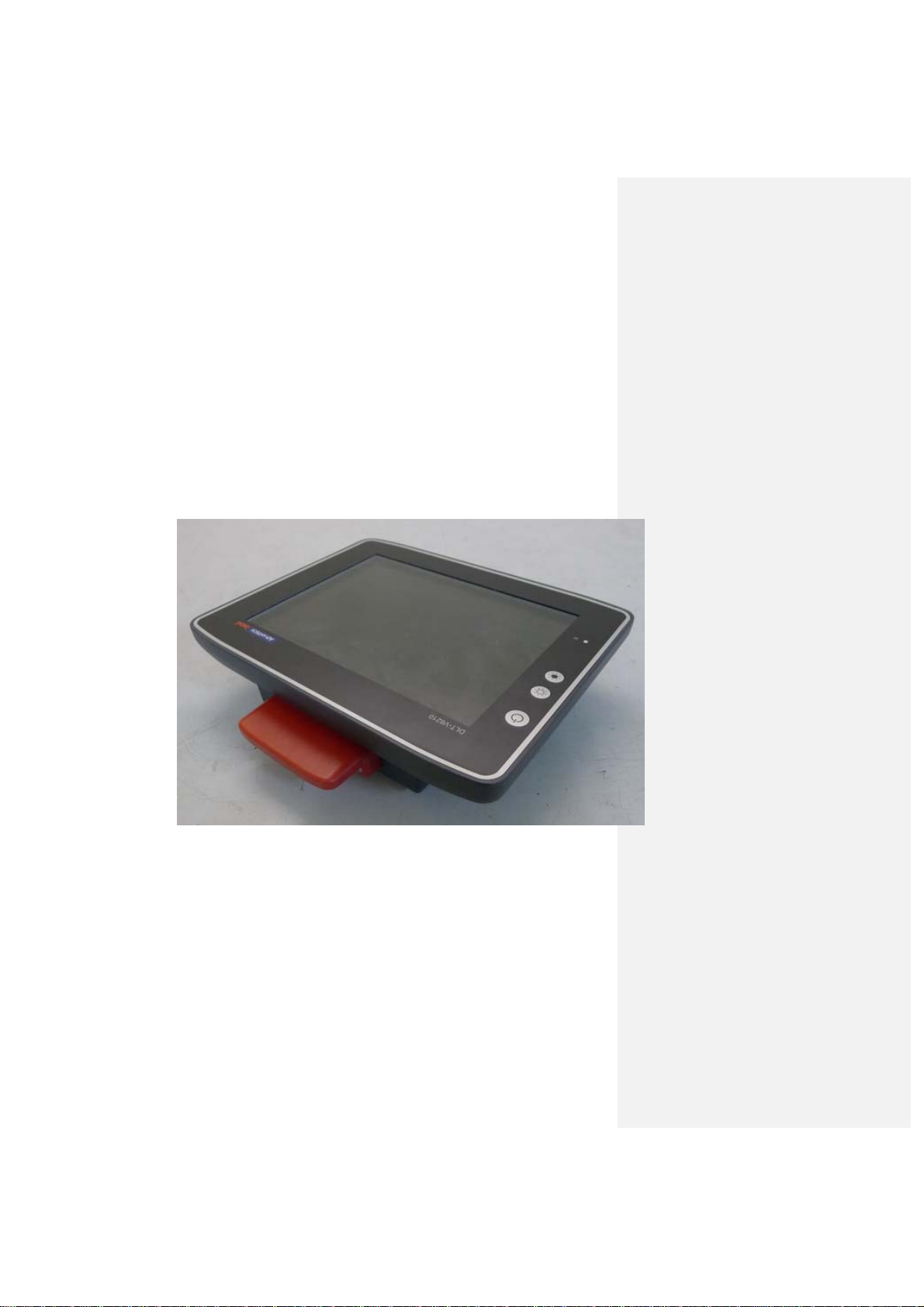
DLT-V6210
DLTV6210XXXXXXXXXXXXXX
(where X may be any alphanumeric character , blank or “-”.)
V 1.00
English
Page 2

IMPORTANT:
Read this manual carefully.
Keep for future reference.
The software and hardware designations as well as the brand names used in this documentation are in most
cases also registered trademarks and are subject to the international law (trademark, brand and patent-protection
laws).
®
Windows
is a registered trademark of Microsoft Corporation in the United States (US) and other countries.
®
RAM
and RAM Mount™ are both trademarks of National Products Inc., 1205 S. Orr Street, Seattle, WA 98108.
DLT-V6210 devices can be delivered with or without preinstalled software. For devices with preinstalled software
observe the associated license agreements.
We recognize all national and international trademarks and product names.
We reserve the right to modify the contents of this manual at any time and without prior notice.
DLoG GmbH assumes no liability for technical inaccuracies, typographic errors or faults in this documentation.
DLoG GmbH also assumes no liability for damages caused directly or indirectly by the delivery, performance or
usage of this material.
This documentation is protected by copyright. No reproduction, also in excerpts, is permitted without the prior
written permission of the DLoG GmbH.
Manual title: DLT-V6210 Industrial PC
Page 3

M
anual completed on:
Manual PN: 2005621010
Manual Version: V1.00
F
CC ID: M82-DLV6210
IC: 9404A-DLV6210
SW: V1.0
HW: V1.0
Copyright 2016
By DLoG GmbH
All rights reserved
DLoG GmbH
Industriestraße 15
D-82110 Germering
Phone (+49) 89 / 41 11 91 0
Fax (+49) 89 / 41 11 91 - 900
info@advantech-dlog.com
www.advantech-dlog.com
Page 4

Table of contents
1. IMPORTANT INFORMATION ABOUT DLT-V6210
MANUALS
5
1.1. Available manuals (in printed form and on the
Internet) 5
1.2. Design elements in the
manual 6
2. FUNCTIONAL
DESCRIPTION
7
2.1. Intended
use 7
2.1.1. Requirements for safe
operation
7
2.1.2.
Permitted environmental
conditions
7
2.2. Mount, operate and service the device
correctly 8
2.3. Warranty
conditions
8
2.4. Device identification/name
plate 9
3. INFORMATION
9
4. EXPLANATION
9
5. DLOG
GMBH
9
3. UNPACKING, TRANSPORT AND
STORAGE
10
Unpacking
3.1.
10
3.2. Transport
10
3.3. Storage
10
3.3.1. Protection of touchscreen during
storage 10
3.4. If return/repacking is
necessary
11
4. DEVICE CONFIGURATION USING SOFTWARE
TOOLS
12
4.1. Configuring the front keys, automatic shut down,
etc. 12
4.2. Wi-Fi configuration
(optional)
12
4.2.1. Radio wave emission
hazards 12
4.2.2. Antenna solutions for use in
rmany
Ge
13
5. MECHANICAL INSTALLATION AT THE DEPLOYMENT
LOCATION
14
5.1. Safety notice – observe before
installing
14
5.1.1. Correct installation
location 14
5.1.2.
Secure
attachment
15
5.1.3.
Handling the
device 16
5.2. Recommended sequence for the mechanical
installation
17
6. ELECTRICAL INSTALLATION, CABLE CONNECTION,
CABLE
COVER
18
6.1. Safety notice – observe before
connecting
18
6.1.1. General
18
6.1.2.
Installing the disconnecting
device 18
6.1.3. Installation of DLT-V6210 on automotive
ects 19
obj
6.2. Preparations
20
6.2.1. Material
required 20
6.3. Inserting the rubber seal in the cable
compartment
21
6.3.1. Plugging in and screwing on the power supply
cable 22
6.3.2. Securing the ground using ring tongue to the ground
t 23
bol
6.3.3. Securing the power supply cable to the strain relief
il 24
ra
6.4. Connecting the USB, Ethernet and COM
cables 25
6.4.1. USB
cable 25
Ethernet
6.4.2.
cable 26
6.4.3.
COM
cable 26
6.5. Closing off unused cable
openings
27
6.6. Attaching the cable
cover 27
Page 5

7.
OPERATION
28
Switching DLT-V6210
7.1.
on/off 28
7.2. Operating the
touchscreen
29
7.3. Front keys and
LEDs 30
7.3.1. Overview
30
7.4. Operating
states 30
8. POWER SUPPLY UNIT, POWER SUPPLY, EXTERNAL
CONNECTORS
31
Integrated power supply
8.1.
unit 31
8.1.1. DC voltage supply
connection
32
8.1.2.
DC Power supply
cable 32
8.2. External connectors under the cable
cover 34
8.3. Service CFast under the antenna
cap 34
8.3.1. Antenna cap
opening/closing
34
8.3.2.
CFast
slot 35
Functional
10.1.
description
40
10.2. Sequence
40
10.3. Configuration
41
11.TECHNICAL
DATA
42
11.1. Environmental
conditions
42
11.2. Projected-capacitive touchscreen
(PCT) 42
11.3. S erial interfa ce
COM1 43
11.3.1. COM1 as a voltage
source
11.4. Network adapter
(10/100/1000)
43
11.5. USB
43
11.6. I nternal spe aker,
sound 43
11.7. Device
dimensions
44
11.8. Position of VESA drill
holes 44
9. OPTIONAL
EQUIPMENT/ACCESSORIES
36
9.1. Integrated low profile
36
9.2. Wi-Fi card
(optional)
37
9.3. Keyboards and keyboard
mounts (optional)
37
9.4. Scanner and scanner
bracket (optional)
38
9.5. Touch
stylus 39
9.6. USB recovery
stick (optional)
39
10. AUTOMATIC SHUT
DOWN
40
12.MAINTENANCE
46
12.1. Do not repair or
modify 46
12.2. Regular checks and maintenance of the complete
system 46
12.3. Cleaning DLTV6210 47
13.MALFUNCTIONS
48
14.REASONABLY FORESEEABLE
MISUSE
49
14.1. O bserve the intended
use 49
14.2. Mobile
application
49
15.GUIDELINES AND
CERTIFICATES
50
15.1. FCC
USA/CAN
50
Page 6

15.
1.
RED (Radio Equipment Directive)
2014/53/EU
50
15.2. CE
marking 51
15.3. Declaration of
conformity
51
16. END-OF-LIFE DEVICE
DISPOSAL
53
TECHNICAL CUSTOMER
17.
SUPPORT
53
RETURN SHIPME NT
18.
FORM
LIST OF
19.
FIGURES
54
Page 7
1. Important information about DLT-V6210 manuals
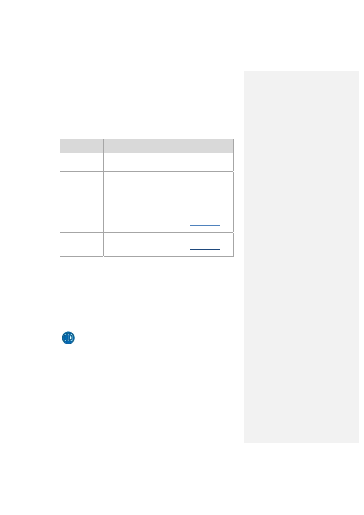
1.1. Available manuals (in printed form and on the Internet)
The following manuals are available for DLT-V6210 Series:
Contents For target
Safety instructions Important information about
Quickstart Guide First steps in commissioning,
Mounting instructions
for accessories
User Manual Complete operating
MDevice description Configuration tool
protecting personnel and
property
mechanical and electrical
installation and mounting
Mounting steps
instructions
group
skilled
personnel
skilled
personnel
skilled
personnel
skilled
personnel
skilled
personnel
Availability
Printed, enclosed with
the device
Printed, enclosed with
the device
Printed, enclosed with
the respective
accessories
PDF file (Download
Center at
www.advantechdlog.com)
PDF file (Download
Center at
www.advantechdlog.com)
Pay attention to these manuals because they help avoid hazards, reduce repair costs and
downtimes, and increase the reliability and service life of DLT-V6210.
Keep the manuals for future use.
Please contact DLoG GmbH if you require additional information or clarification. You can find the
contact address in section Technical customer support.
Curre
nt manual versions
The latest versions of our manuals are available at our website:
www.advantech-dlog.com -> Download -> Products
A
dvantech-DLoG DLT-V6210 Manual V1.00 Page 5 / 60
Page 8
1.2. Design elements in the manual
he following design elements are used in this manual:
T
DANGER / WARNING / CAUTION
DANGER means that death or severe bodily injury will occur if this information is not observed.
WARNING means that death or severe bodily injury can occur if this information is not
observed.
CAUTION means that slight bodily injury can occur if this information is not observed.
NOTICE: Physical damage
Information about possible physical damage
TIP / HINT
Tips, hints for using the product
N
ote about additional information in manuals
P
age 6 / 60 DLT-V6210 Manual V1.00 Advantech-DLoG
Page 9

2. Functional description
2.1. Intended use
DLT-V6210 industrial PCs are data communication terminals for using in commercial environments (e.g.
logistics, warehouse, manufacturing). Any other or additional use beyond this shall be deemed improper
use. The user/operator of DLT-V6210 is solely responsible for any resulting damage. This also applies to
any unauthorized modifications made to the device.
DLT-V6210 industrial PCs:
are not approved for using in EX zones (potential explosion hazard).
are not approved for using on ships.
are not approved for using in life-support systems or critical safety systems where system
malfunction can lead to direct or indirect endangerment of human life.
Indented use includes the following:
The compliance with all safety instructions.
The compliance with the approved environmental conditions and specifications for the device.
2.1.1. Requirements for safe operation
The requirements are:
Proper transportation and storage.
Proper setup and use.
Proper maintenance and service.
Operation by trained personnel.
2.1.2. Permitted environmental conditions
DLT-V6210 industrial PCs may only be used under specified environmental conditions.
See section 11.1 Environmental conditions.
A
dvantech-DLoG DLT-V6210 Manual V1.00 Page 7 / 60
Page 10

2.2. Mount, operate and service the device correctly
DLT-V6210 industrial PCs were designed and built according to modern technology and accepted safety
regulations. However, the operation of DLT-V6210 can endanger personnel or third parties and cause
damage to the device and other material assets when, for example, the device is
installed incorrectly or configured improperly.
operated by untrained or uninstructed personnel.
improperly operated and maintained.
not used as intended.
The owner/operator commitments with regards to safety (accident
safety) are to be followed.
2.3. Warranty conditions
For DLT-V6210 industrial PCs, accessories the Advantech-DLoG TOB regulations are valid (section
Liability for defects -> limitation period for claims).
Find details on the Advantech-DLoG Internet homepage.
LCD display
The LCD display of DLT-V6210 series fulfills the highest quality standards and was inspected for pixel
defects. However, due to technological reasons pixel defects can occur.
This is not a malfunction; it is a part of the technical specifications.
prevention regulations, occupational
Pa
ge 8 / 60 DLT-V6210 Manua l V1.00 Advantech-DLoG
Page 11
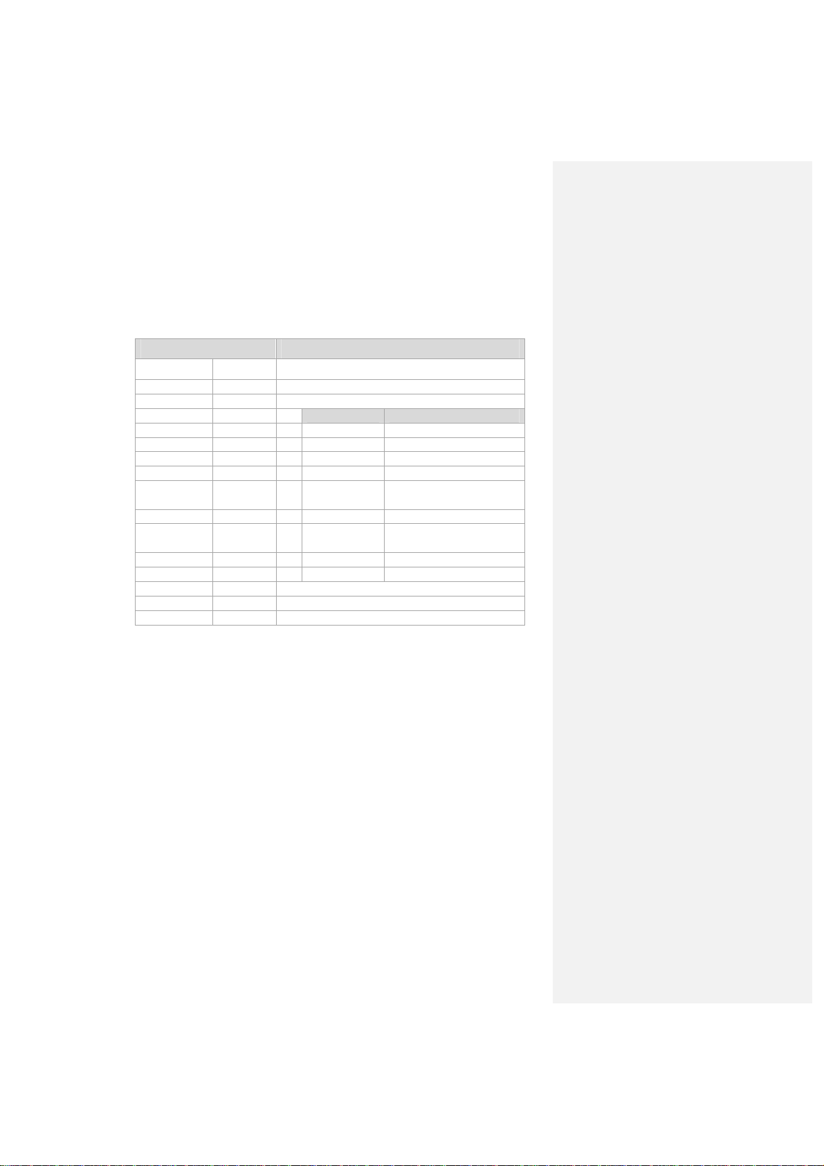
2.4. Device identification/name plate
The name plate is located on the rear side of DLT-V6210. It must remain legible at all times for the
purpose of identifying the device.
Do not damage the name plate or remove it from the device.
Information about the name plate:
Information Explanation
DLoG GmbH
Model DLT-V6210 Device name
9-digit ID Identification code (characters from left to right)
Input V / A Input voltage of DC power supply unit nominal current
S/N Serial number: Specific Advantech-DLoG device code
Barcode For Advantech-DLoG internal purposes
Manufacturer contact information
Component Explanation
9 Core processor 7 : x86 Bay Trail
10 Front unit P : PCAP
11 Storage L: 32G MLC CFast
12 Power supply 1 : 12/24/48 VDC :
13 OS
14 LTE 0 : No LTE/GPS
15WIFI
16 Revision number 0
17 RoHS appliance E : oHS
E : WES8
P : Win 7 pro
0 : No WIFI
W : WIFI
nt: X stands for not present / not applicable respectively as placeholder for add-ons.
Comme
A
dvantech-DLoG DLT-V6210 Manual V1.00 Page 9 / 60
Page 12
3. Unpacking, transport and storage
3.1. Unpacking
Open the packaging carefully to prevent damaging the device inside.
Save the packaging material (for possible forwarding transportation or return of DLT-V6210).
Check the shipment for completeness and any possible damage.
Always keep the supplied manuals and documents.
3.2. Transport
WARNUNG
Risk of injury due to weight and sharp-edged parts.
DLT-V6210 can fall down and cause injuries due to its weight.
The strain relief rail can have sharp edges and cause cutting injuries.
Always hold DLT-V6210 by the housing with both hands.
Never use the antenna cap as a handle. It can break due to the weight
involved.
Do not hold DLT-V6210 by the strain relief rail.
Use the assistance of a second person for installation work.
3.3. Storage
Observe the permissible storage temperature range in the manual, section
11.1 Environmental conditions.
3.3.1. Protection of touchscreen during storage
NOTICE: Physical damage
Damage to the touchscreen due to incorrect storage.
Protect touchscreen from sharp edges, impacts, and heavy objects.
If stacking, do not stack higher than two devices.
Place devices front-to-front in this case.
The VESA mounting point on the rear side of the device can damage the
touchscreen of another device.
Use protective material (non-flammable!) between the devices as
precaution.
P
age 10 / 60 DLT-V6210 Manual V1.00 Advantech-DLoG
Page 13

3.4. If return/repacking is necessary
If DLT-V6210 is being returned to the manufacturer, a completely filled-out return package slip must be
enclosed with every DLT-V6210.
You can find this return package slip:
at the end of this manual
and on the Internet at www.advantech-dlog.com
f you repack the device, please ensure that the cling wrap in the cardboard frame is positioned towards
I
the front of the device so that it can provide the proper protection.
A
dvantech-DLoG DLT-V6210 Manual V1.00 Page 11 / 60
Page 14
4. Device configuration using software tools
WARNING
Risk of injury and damage due to improper configuration.
These instructions are directed to skilled personnel.
Only qualified skilled personnel (e.g. IT personnel with good knowledge of
PCs, operating systems and wireless networks) may configure DLT-V6210.
If DLT-V6210 is incorrectly configured, the DLoG GmbH warranty for this device will be void.
4.1. Configuring the front keys, automatic shut down, etc.
The MDevice software is used to configure DLT-V6210 devices with Microsoft Windows operating
system.
Configuration examples:
Automatic shut down
Network settings
The MDevice manual is available in the Download Center at www.advantech-
dlog.com.
4.2. Wi-Fi configuration (optional)
Depending on the optional equipment and intended use of DLT-V6210, the settings and access data for
Wi-Fi networks should be defined.
4.2.1. Radio wave emission hazards
This information applies exclusively to DLT-V6210 devices that are equipped with wireless technology.
CAUTION
Excessive radio wave emission due to incorrect Wi-Fi configuration.
Risks to health are possible due to excessive radio wave emission if the transmission power
and the frequency are set incorrectly during the Wi-Fi configuration.
Observe the applicable regulations for your deployment location/country
with regard to frequencies and the maximum permissible transmitting power.
Responsibility for this lies with the company who is operating DLT-V6210.
The regulatory authorities in the relevant country can provide information on
this.
P
age 12 / 60 DLT-V6210 Manual V1.00 Advantech-DLoG
Page 15
Country-specific regulations
Example for Germany: In Germany according to regulations published in the gazette 89/2003 of the
RegTP (regulating body for telecommunications and mail, now: “Bundesnetzagentur”) - Federal Network
Agency for electricity, gas, telecommunications, post and railway - the maximum permissible transmitting
power, EIRP (Equivalent Isotropically Radiated Power), in the 2.4 GHz frequency band is set at 20 dBm
(100 mw).
Set the transmitting power of the Advantech-DLoG antenna so that the permitted EIRP limit value is
complied with.
Examples for worldwide:
Region Regulatory authority
EU
China CNCA-07C-031
Japan Japan SDoC, Certificate
Taiwan Taiwan Certification
Canada Canada Certification Body
USA USA Certification
Brazil Brazil Certification and Homologation
Russia Russian Certification
Argentina Argentinian Certification, CNC
ARNING
W
Electromagnetic radio frequency energy can interfere with technical devices.
Some technical equipment in hospitals and aircraft is not shielded against radio frequency
energy.
DLT-V6210 industrial PCs can affect the functioning of implanted medical devices such as
pacemakers and cause them to malfunction.
EU Verification Notified Body
Do not use DLT-V6210 in aircraft or hospitals without receiving prior
authorization.
Usage in both occasions is only permitted if such authorization has been
obtained.
Do not use DLT-V6210 near pacemakers.
Always keep a distance of at least 20 cm between a pacemaker and
DLT-V6210 to reduce the risk of interference.
Before using the device please obtain information about the use of the
device within certain areas (e.g. airports, hospitals, etc.) and also about
the respectively applicable regulations and obtain an approval for the
operation of the device, if necessary.
V1.9.1 ETSI
4.2.2. Antenna solutions for use in Germany
The Advantech-DLoG antenna solutions are based on the prevailing IEEE 802.11 standard. This
standard allows wireless data transfer at rates from 1 Mbps to 54 Mbps (300 Mbps if using
IEEE 802.11n) using the 2.4 GHz and 5 GHz frequency band.
A
dvantech-DLoG DLT-V6210 Manual V1.00 Page 13 / 60
Page 16
5. Mechanical installation at the deployment location
5.1. Safety notice – observe before installing
WARNING
Risk of injury and damage due to improper mechanical installation.
These mounting instruction are directed to skilled personnel.
Only qualified skilled personnel may perform the mechanical installation
work
on DLT-V6210.
If DLT-V6210 is incorrectly mounted, any DLoG GmbH warranty for this device will be void.
5.
1.1. Correct installation location
WARNING
Risk of injury and damage due to improper deployment location.
Observe the intended use of DLT-V6210, e.g. not in potentially explosive
areas, not in life-supporting facilities.
Ensure that the deployment location of DLT-V6210 complies with the
permissible environmental conditions.
WARNING
Risk of accident on the targeted objects due to limited field of view of the user.
User’s field of vision must remain free.
During installation, reserve sufficient space for DLT-V6210 and related
accessories.
Make sure that the user's field of vision is not restricted in a prohibited way
when mounting peripheral devices.
CAUTION
Radio wave emission in the vicinity of persons.
To ensure that the limits set for exposure to radio waves are not exceeded:
Install DLT-V6210 so that persons maintain a minimum distance of 20 cm to
the antenna.
P
age 14 / 60 DLT-V6210 Manual V1.00 Advantech-DLoG
Page 17
NOTICE: Physical damage
Installation environment without cooling air can overheat/damage DLT-V6210.
DLT-V6210 employs a passive cooling concept whereby the waste heat generated inside the
device is emitted from the surface of the housing.
For this system to work/operate properly, sufficient fresh air circulation is required.
If there is no access to fresh cooling air, it may result in overheating and severe damage to the
device.
Never install the system in a closed environment where the cooling air is unable to dissipate
accumulated heat to the outside.
The maximum permissible ambient temperature for the entire system needs to be taken into
account for the specific application area.
5.1.2. Secure attachment
Observe the following information about the mounting brackets:
All brackets and mounting parts supplied by Advantech-DLoG are only intended to be used for
attachment of the industrial PCs and the peripheral devices and may not be misused.
Only use suitable mounting brackets and screws permitted by Advantech-DLoG.
Ensure that ball-and-socket bases and mounting brackets are always attached correctly.
Risk of accident on the target objects due to unexpected emergency stop because of
electroconductive connection of DLT-V6210 to the targeted object chassis.
Due to a variety of technical properties of forklifts and forklift trucks, it can be necessary to
electrically isolate DLT-V6210 from the chassis of the targeted object to prevent malfunctions.
The necessity of this must be studied on a case-by-case basis, however, it is recommended for
targeted objects’ with potential-free chassis.
Please observe the mounting instructions supplied with the optional brackets.
DANGER
For example, using rubber buffers ensures that the terminal has no
electrically conducting connection to the chassis.
If peripheral equipment (such as scanners, printers, scales or similar) which
has its own power supply unit to be used, you must ensure that the power
supply units of these peripherals are galvanically separated from the supply
of the targeted obect. Moreover, the peripheral equipment and its cabling
must be attached electrically isolated.
If antennas are being used, you must ens
isolated at the mounting point on the targeted object chassis.
ure that the antennas are
A
dvantech-DLoG DLT-V6210 Manual V1.00 Page 15 / 60
Page 18
Risk of accident on the targeted objects due to unstable attachment of DLT-V6210.
5.
1.3. Handling the device
Hazardous voltage, electrical shock from contacting with live parts.
Risk of injury due to weight and sharp-edged parts.
DLT-V6210 can fall down and cause injuries due to its weight.
The strain relief rail can have sharp edges and cause cutting injuries.
WARNING
When installing DLT-V6210, make sure that no one will be injured if the
bracket breaks (e.g. because of a stress fracture).
Alternatively you can put appropriate safety measures in place (e.g. install a
security cable in addition to the mounting bracket).
WARNING
Do not put DLT-V6210 into operation if it is visibly damaged.
Do not open or modify DLT-V6210.
WARNING
Always hold DLT-V6210 by the housing with both hands.
Never use the antenna cap as a handle. It can break due to the weight
involved.
Do not hold DLT-V6210 by the strain relief rail.
Use the assistance of a second person for installation work.
NOTICE: Physical damage
Damage and scratching of the touchscreen without transportation protective film.
The front display of DLT-V6210 is protected during transportation by a transparent film. This film
should remain on the front display during assembly to avoid damage to the front display surface.
Only remove the film after all of the installation work has been completed.
P
age 16 / 60 DLT-V6210 Manual V1.00 Advantech-DLoG
Page 19

5.2. Recommended sequence for the mechanical installation
Requirement: The installation location must be prepared (e.g. connection to the ignition, correct
voltage, etc.)
We recommend the following sequence for the mechanical and electrical installation:
1. Determine a suitable mounting position for DLT-V6210.
2. Secure device mounting at the targeted object (RAM Mount etc.).
3. Connect external accessories to DLT-V6210.
4. Install an easily accessible disconnecting device, such as a switch close to the device.
5. Connect all cables.
6. Close DLT-V6210 with cable cover.
7. Mount DLT-V6210 on the device mounting bracket.
A
dvantech-DLoG DLT-V6210 Manual V1.00 Page 17 / 60
Page 20

6. Electrical installation, cable connection, cable cover
6.1. Safety notice – observe before connecting
6.
1.1. General
WARNING
Risk of injury and damage due to improper electrical installation.
These instructions are directed to skilled personnel.
Only qualified skilled personnel are permitted to perform the electrical
installation of DLT-V6210.
Comply with the appropriate national installation regulations for all cable
routing.
1.2. Installing the disconnecting device
6.
WARNING
Electrical shock due to lack of disconnecting device.
DLT-V6210 industrial PCs are not equipped with disconnecting devices that are accessible from
outside; they do not have switches.
To enable the devices to be quickly disconnected from the power supply in emergency
situations:
Install an easily accessible disconnecting device such as a switch close to
the device.
Make sure that the disconnecting device disconnects all power supply lines.
WARNING
Deployment location in fueling stations, chemical plants.
The operation of electrical equipment at locations where flammable gases or vapors are present
poses a safety hazard.
Turn off DLT-V6210 when you are near gas stations, fuel depots, chemical
plants or places where blast might take place.
P
age 18 / 60 DLT-V6210 Manual V1.00 Advantech-DLoG
Page 21

6.1.3. Installation of DLT-V6210 on automotive objects
DANGER
Electrical shock due to insufficient EMERGENCY shut-off swithch.
If the EMERGENCY-OFF switch of the automotive object does not switch off DLT-V6210, there
is a risk of electrical shock.
Install DLT-V6210 and the EMERGENCY-OFF switch so that DLT-V6210
also switches off when the EMERGENCY-OFF switch is operated.
NOTICE: Physical damage
Overvoltage on DLT-V6210 when charging the targeted object’s battery.
DLT-V6210 must be disconnected from the battery while the battery is being charged.
Or it must be ensured that the maximum permitted input voltage of DLT-V6210 is not
exceeded.
A
dvantech-DLoG DLT-V6210 Manual V1.00 Page 19 / 60
Page 22

6.2. Preparations
Lay out all cables which are ready to be connected to DLT-V6210.
Select the appropriate slot on the connector panel of DLT-V6210.
Check and test which order of the cables routing is the best to fit in the cable compartment.
6.2.1. Material required
Cable sealing set (scope of delivery: cable cover)
Cable cover
Rubber seal
Cable clips Screws
P
age 20 / 60 DLT-V6210 Manual V1.00 Advantech-DLoG
Page 23

Tools
Hexagon screwdriver, size 3
Philips screwdriver, size 3
Torque wrench
Flat head screwdriver, size 0
Socket wrench, size 7
6.3. Inserting the rubber seal in the cable compartment
Select suitable rubber seal which diameter of middle hole can fit the cable’s diameter.
There’s opening on the rubber seal, please open it and put the cable through it.
Place the rubber seal in the frame of the cable compartment (see figure).
Press the plugs of the rubber seal into the holes of the frame.
If there’s no cable in the compartment, please put dummy rubber seal into it.
Fig. 6.1: Rubber seal inserted in the cable compartment
WARNING
Electrical shock or fire due to incorrect cable routing or insufficient grounding.
Only use original Advantech-DLoG power cables; they meet the specific requirements for
low-temperature flexibility, UV resistance, oil resistance, etc.
Make sure that the power supply cables are running without kinks and protected (securely
protected against crushing and abrading).
DLT-V6210 may only be connected to a SELV circuit (Safety Extra Low Voltage). The
SELV circuit is a secondary circuit that is designed to protect the voltage from exceeding
the safe value when operation runs correctly or a single error occurs.
The DC+ connecting cable must be protected by a fuse (30 AT max.).
The ignition connecting cable must be protected by a fuse of the following type:
5x20 mm T 125 mA L / 250 V, for example, a Wickmann 195-125 mA / 250 V.
Observe the correct voltage ranges.
Ensure that power supply cables are fused correctly.
Read the labeling on the cable and connect the power supply cable with the correct
polarity.
Cut the power supply cable to the minimum length. This avoids cables being tangled and
improves the quality of the power supply.
Connect the power supply cable to a suitable place. Ensure that the connecting cable has
an adequate cross section and ampacity at the connection point.
ntech-DLoG DLT-V6210 Manual V1.00 Page 21 / 60
Adva
Page 24

NOTICE: Physical damage
Observe the potential ratios.
On DLT-V6210, logic ground and shield ground are firmly connected to each other.
Logic ground is the ground (GND) used to supply the internal parts and components such as the
display or CPU. All cable shields and the housing are connected to shield ground.
The chassis of some forklifts is on DC+. This means that DLT-V6210 chassis is also on DC+.
Short circuits can arise when, for example, the ground potential of a peripheral device is on DC-.
This may cause malfunctions or irreparable damage to DLT-V6210.
Always attach the ring tongue of the power supply cable to the provided
ground bolt situated on the connector panel.
The other end of the yellow-green power supply cable must be connected to
the targeted object’s chassis.
Connect the power supply cable of DLT-V6210 as directly as possible to the
battery and not to the power supply lines (e.g. the engine power supply)
which a great deal of interference or otherwise affected by consumers.
Connecting DLT-V6210 to large electrical loads, such as converters for the
forklift motor may result in random restarts, malfunctions and/or irreparable
damage to the device.
If you want to connect devices fed by other power sources to DLT-V6210
(e.g. printers), be sure to power up the peripheral devices at the same time
or after DLT-V6210; otherwise, you may encounter start-up problem,
malfunctions or even irreparable damage to the device.
Plugging in and screwing on the power supply cable
6.3.1.
Fig. 6.2: The power supply cable secured and inserted in rubber seal
Plug the power supply cable into the
power supply plug-in location.
Tighten both mounting screws hand-
tight.
Fold-open the round cable passage in
the rubber seal.
Insert the power supply cable.
Page
22 / 60 DLT-V6210 Manual V1.00 Advantech-DLoG
Page 25

6.3.2. Securing the ground using ring tongue to the ground bolt
Fig. 6.3: Ring tongue secured to the ground bolt
Secure the ring tongue of the power supply cable to the ground bolt.
1
2
3
ATTENTION
To make sure the device is grounding correctly, it
is important to follow the correct order to put the
components on the ground bolt as below (from
inside to outside):
1. Place “toothed washer“ first(internal).
2.
Then put the “Ring Tongue of the power
supply cable” (flat side faces DLT-V6210
connector panel).
3. Tightening the nut hand-tight.
Adva
ntech-DLoG DLT-V6210 Manual V1.00 Page 23 / 60
Page 26

6.3.3. Securing the power supply cable to the strain relief rail
Put the rubber seal into the compartment with power cable in the center of the rubber seal first.
Place one cable clip on the power supply cable.
Secure the cable clip to the strain relief rail using 2 mounting screws
(M3x10 screws).
Tighten the mounting screws alternatingly
ATTENTION: Tighten the mounting screws sufficiently but on no account pinch or crush the cable.
If you do, the cables may break or the cable insulation may get damaged.
Fig. 6.4: Cable clip secured to the strain relief rail.
Page
24 / 60 DLT-V6210 Manual V1.00 Advantech-DLoG
Page 27

6.4. Connecting the USB, Ethernet and COM cables
NOTICE: Physical damage
Observe the following instructions when connecting/removing external devices to/from
DLT-V6210.
Only use accessories that have been tested and approved by Advantech-DLoG for the
respective DLT-V6210.
DLT-V6210 may not be connected to the power supply if external devices
are being connected/removed (not applicable for USB devices)
Otherwise considerable damage could be caused to both DLT-V6210 and
the peripheral devices.
Make sure that peripherals with their own power supply are either switched
on at the same time as DLT-V6210 or after the start of DLT-V6210.
Otherwise, you must ensure that the backflow from the external device to
DLT-V6210 cannot take place.
Only power up DLT-V6210 when all devices are completely connected and
DLT-V6210 is closed correctly (remember the cable cover!). Otherwise, you
may damage DLT-V6210.
e observe the mounting instructions supplied with the optional accessory.
Pleas
6.4.1. USB cable
Plug the required USB cable into the associated port.
Insert the USB cable
Put the rubber seal into the compartment with USB cable in themiddle of the rubber seal.
Secure the USB cable to the strain relief rail with cable clips and screws.
ATTENTION: Tighten the mounting screws sufficiently but on no account pinch or crush the cable.
If you do, the cables may break or the cable insulation may get damaged.
Fig. 6.5: USB cable on the connector panel; secured to the strain relief rail
Adva
ntech-DLoG DLT-V6210 Manual V1.00 Page 25 / 60
Page 28

6.4.2. Ethernet cable
Plug the Ethernet cable into the associated port.
Insert the Ethernet cable.
Put the rubber seal into the compartment with Ethernet cable in themiddle of the rubber seal.
Secure Ethernet cable to the strain relief rail with cable clips and screws.
ATTENTION: Tighten the mounting screws sufficiently but on no account pinch or crush the cable.
If you do, the cables may break or the cable insulation may get damaged.
Fig. 6.6: Ethernet cable on the connector panel; secured to the strain relief rail
6.4.3. COM cable
Plug the required COM cable into the associated port.
Insert the COM cable.
Put the rubber seal into the compartment with COM cable in themiddle of the rubber seal.
Secure the COM cable to the strain relief rail with cable clips and screws.
ATTENTION: Tighten the mounting screws sufficiently but on no account pinch or crush the cable.
If you do, the cables may break or the cable insulation may get damaged.
Fig. 6.7: COM cable on the connector panel; secured to the strain relief rail
Page
26 / 60 DLT-V6210 Manual V1.00 Advantech-DLoG
Page 29

6.5. Closing off unused cable openings
Close off all unused cable openings with the blind plug type of rubber seal so that they can be
sealed.
Fig. 6.8: Unused cable outlets sealed off with blind plugs
6.6. Attaching the cable cover
NOTICE: Physical damage
The device is not completely sealed due to incorrect attachment of the cables and the
cable cover.
The protection class/category of DLT-V6210 is only ensured if the cable cover is properly
installed.
Improper installation can result in liquid penetrating into DLT-V6210 during operation. This will
cause the risk of short-circuiting, corrosion and wear.
Place the cable cover in DLT-V6210 housing slot.
Lock the screws loosely into the holes of the cable cover.
Then fully tighten the screws with 3 Nm torque.
Fig. 6.9: Cable cover closed and screwed together
Adva
ntech-DLoG DLT-V6210 Manual V1.00 Page 27 / 60
Page 30

7. Operation
7.1. Switching DLT-V6210 on/off
The following factors determine how DLT-V6210 can be switched on and off:
Is DLT-V6210 mounted on a automotive object and connected to the ignition signal?
What are the automatic shut down settings that were defined in the MDevice configuration
program?
Switch on
Switch DLT-V6210 on as follows, depending on the configuration:
Press the <Power> button.
Or: Through the ignition signal of the targeted object (depends on the automatic shutdown settings).
Fig. 7.1: <Power> button
Switch off
Switch DLT-V6210 off as follows, depending on the configuration:
Press the <Power> button of the activated DLT-V6210.
Or: Disconnect the supply voltage.
NOTICE
: Devices will be hard-terminated (data loss possible).
Or: Deactivate the ignition of the connected targeted object (depends on the automatic shut down
settings).
Time between switching off and on: 10 seconds
After DLT-V6210 is shut down and switched off, it needs to wait at least 10 seconds until the device can
react to a switch-on signal (<Power> button / ignition).
28 / 60 DLT-V6210 Manual V1.00 Advantech-DLoG
Page
Page 31

7.2. Operating the touchscreen
NOTICE: Physical damage
Improper operation can cause damage and downtimes to DLT-V6210 and to the
connected complete system.
Operators of DLT-V6210 must be trained in the handling of the device.
revent damage to the touchscreen
P
Keep the touchscreen clean.
Do not touch the touchscreen with pointed, sharp, rough or hard objects, e.g. ball point pens, writing
implements, tools of any kind (e.g. screwdrivers).
Make sure that no adhesives get on the surface of the touchscreen.
Ensure that the touchscreen surface is not influenced by high voltages or static electricity.
Do not use excessive force when touching the touchscreens, and do not hit or press hard.
If the device with the touchscreen is placed down: Place a clean, soft cloth underneath.
Operating the touchscreen
Clean, dry fingers.
Clean, dry, soft gloves.
Suitable touch stylus with capacitive (electrically conductive) tip.
NOTICE: Physical damage
Salty water on the PCT touchscreen can be interpreted as a "touch" and lead to malfunction.
Mu
lti-touch capability
Depending on the installed operating system type, the PCT touchscreen of DLT-V6210 is multi-touch
capable. This means it can detect two touch points simultaneously.
Adva
ntech-DLoG DLT-V6210 Manual V1.00 Page 29 / 60
Page 32

7.3. Front keys and LEDs
7.3.1. Overview
Fig. 7.2: Operating elements: Front keys and LED
Keys:
- Power on/off
- LCD Brightness up
- LCD Brightness down
LED:
System Status LED Status
System power on Static
System power off Off
System over/under
tempertuare
System thermal
sensor faculty
NOTICE: Physical damage
Improper operation can cause damage and downtimes to DLT-V6210 and to the
connected complete system.
Operators of DLT-V6210 must be trained in the handling of the device.
Blinking
0.2 sec. on / 0.8 sec. off
Blinking
0.5 sec. on / 0.5 sec. off
7.4. Operating states
Status of LEDs DLT-V6210 status
Supply voltage
(green)
OFF
STATIC ON
Blinking : 0.2 sec. on / 0.8 sec. off Temperature sensor faulty
Blinking : 0.5 sec. on / 0.5 sec. off
Page 30 / 60 DLT-V6210 Manual V1.00 Advantech-DLoG
Waiting for a new ignition signal or activation
of the <Power> key after switch-off; no
Computer start-up/normal operational
state/shutdown delay time
Ambient temperature lies beyong the
permitted range, i.e. < -30 or > +50 °C
voltage supply
Page 33

8. Power supply unit, power supply, external connectors
8.1. Integrated power supply unit
DLT-V6210 is equipped with a galvanically separated, integrated DC power supply unit.
Power is connected to the back of the unit using a Phoenix Contact plug.
There is no power switch.
Power supply
DC power pack
12/24/48 VDC
(wide-range power supply unit)
Voltage range 9 to 60 VDC
Maximum output power Vin < 36V => 42W
Nominal current
Connection to SELV circuit only The SELV circuit is a secondary circuit that is designed
Power consumption
DLT-V6210 Typically 34 W
Power supply unit fuses
Power supply unit Fuse type Example
Advantech Dlog
owned- design
power supply unit
The symbol of the fuse is FA. You will find the exact position on the sticker located on the connection
plate of DLT-V6210.
5 x 20 mm, 8 A, 250 V LittleFuse 0477008.MXP
12/24/48 VDC nominal
Galvanically isolated
Withstands bursts up to 2 kV
Vin > 36V => 50.4W
12V -- 3.5A
24V -- 1.75A
48V -- 0.875A
to protect from the voltage exceeding the safe value
when operation runs correctly or if a single error occurs.
or similar product produced by other
manufacturers
Advantech-DLoG DLT-V6210 Manual V1.00 Page 31 / 60
Page 34

8.1.1. DC voltage supply connection
Version: Phoenix Combicon, 3-pin.
External view:
Fig. 8.1: DC power supply connector with power cable connector detail view
Explanation:
“Ignition on” means that a control signal can be routed to this connection that matches the supply
voltage level. The signal reference is DC-.
8.1.2. DC Power supply cable
Fig. 8.2: DC Power supply cable with Phoenix Combicon, 3-pin
Page 32 / 60 DLT-V6210 Manual V1.00 Advantech-DLoG
Page 35

WARNING
Electrical shock or fire due to incorrect power supply cable.
Only use original Advantech-DLoG power supply cables; these meet the specific
requirements for low-temperature flexibility, UV resistance, oil resistance, etc.
Fig. 8.3: DC connection cable pin assignment
Advantech-DLoG DLT-V6210 Manual V1.00 Page 33 / 60
Page 36

8.2. External connectors under the cable cover
Fig. 8.4: External connectors of DLT-V6210
8.3. Service CFast under the antenna cap
NOTICE: Physical damage
Improper opening of the antenna cap can impair the function of entire DLT-V6210 system and in
particular the Wi-Fi functionality.
The antenna cap may only remain open during the service work.
No objects or liquids may enter the opened DLT-V6210 during this.
Only when the antenna cap is properly closed again may operation be resumed; the protection
class/category is only ensured again after doing so.
8.3.1. Antenna cap opening/closing
Opening
Loosen the two screws of the antenna cap using Torx screwdriver.
Carefully lift up the antenna cap.
Page 34 / 60 DLT-V6210 Manual V1.00 Advantech-DLoG
Page 37

Fig. 8.5: Antenna cap opened
Closing
Place the antenna cap back onto DLT-V6210.
The antenna cap seal must not be damaged; it must be seated correctly in the groove.
Tighten the two screws of the antenna cap again (1 Nm torque).
8.3.2. CFast slot
There is a CFast slot under the antenna cap.
Exercise special care when removing and re-inserting CFast card.
Only use CFast cards that have been approved by Advantech-DLoG.
Advantech-DLoG DLT-V6210 Manual V1.00 Page 35 / 60
Page 38

9. Optional equipment/accessories
9.1. Integrated low profile Wi-Fi antenna (optional)
Fig. 9.1: Integrated low profile Wi-Fi antenna (optional)
Technical data
Application Wi-Fi IEEE 802.11 a/b/g/n Dual Band Diversity
Number of antennas 2
Type Omnidirectional antenna
Directionality Optimized for the DLT-V6210 housing
Antenna gain
Impedance 50 Ω
Polarization Vertical/Horizontal
Maximum transmitting power 100 mW / 20 dBm
60 DLT-V6210 Manual V1.00 Advantech-DLoG
Page 36 /
2.4GHz :6.5 dBi / 5GHz:2.5 dBi
Page 39

9.2. Wi-Fi card (optional)
Technical data
Wi-Fi PCIe MiniCard
Driver
Maximum radiated power 100 mW EIRP
Integrated in the device at the factory by Advantech-DLoG
(internal PCIe MiniCard slot).
Generally, only drivers for Wi-Fi cards approved by
Advantech-DLoG can be integrated into operating system
images.
9.3. Keyboards and keyboard mounts (optional)
Any USB keyboard can be connected to DLT-V6210.
Advantech-DLoG offers the following keyboards:
Fig. 9.2: SMALL keyboard
SMALL keyboard
Mountable
Protection class IP65
Keyboard layouts: German, English,
French
Fig. 9.3: 24-key keypad
24-key keypad
Mountable
Protection class IP65
Fig. 9.4: Keyboard mounting examples
Adva
ntech-DLoG DLT-V6210 Manual V1.00 Page 37 / 60
Page 40

9.4. Scanner and scanner bracket (optional)
You can connect scanners to either the USB interface or the serial interface.
Please contact your Advantech-DLoG sales representative if needed.
If connected to COM1, the scanner can be powered through the interface with a voltage of 5 V.
Use only scanners that have been approved by Advantech-DLoG.
Optional scanner brackets are available for DLT-V6210.
Fig. 9.5: Example scanner bracket
Page
38 / 60 DLT-V6210 Manual V1.00 Advantech-DLoG
Page 41

9.5. Touch stylus
Advantech-DLoG offers some touch stylus pens (with associated mountings) for resistive and PCT
touchscreens. Please contact your Advantech-DLoG sales representative if needed.
Use only touch stylus that have been approved by Advantech-DLoG.
Fig. 9.6: Example touch stylus for PCT touchscreen
9.6. USB recovery stick (optional)
The optional Advantech-DLoG recovery stick allows images to be backed up and restored onto DLTV6210 when necessary (backup & recovery).
Please contact your Advantech-DLoG sales representative if needed.
Adva
ntech-DLoG DLT-V6210 Manual V1.00 Page 39 / 60
Page 42

10. Automatic shut down
10.1. Functional description
DLT-V6210 is equipped with an automatic shut down module.
If wired up accordingly, DLT-V6210 conveniently switches off together with the ignition.
As disconnecting the power supply during operation can lead to data loss, the operating system needs
to be shut down normally by using the appropriate hardware and software installed on the system when
the ignition is switched off.
DLT-V6210 is connected with three supply cables.
DC+ and DC- are directly connected to the power supply, the connection is of course run through fuses.
The supply voltage is then linked to DLT-V6210’s ignition input via a switch, for example, the key switch
of the ignition (also with a fuse).
10.2. Sequence
When the ignition is turned on or DLT-V6210 <Power> button is pressed, DLT-V6210 checks its internal
temperature and runs a test to confirm that the automatic shut down function is working.
If the check of the environmental conditions is successful, DLT-V6210 starts the operating system
normally.
Once these checks are completed, DLT-V6210 starts the operating system. No environmental conditions
(e.g. the internal temperature of the device or the state of the ignition input) are checked for one minute
during startup.
After one minute, DLT-V6210’s internal temperature and the state of the ignition input are constantly
monitored.
If DLT-V6210’s internal temperature reaches a critical level, shutdown of the operating system will be
carried out. The computer will remain switched off until the temperature is once again within the
permitted range.
If the ignition input is grounded or isolated during normal operation of DLT-V6210, the device will switch
to a delayed shut-off state.
The device will continue to operate normally in this state until the shut-off delay (e.g. 20 minutes) has
elapsed.
If the ignition is turned on again during this shut-off delay, DLT-V6210 will revert to a normal operational
state.
Once the shut-off delay (afterrun time) has elapsed, the operating system will shut down and the device
will automatically shut down (e.g. after one minute or a signal from the operating system).
Device shut down
If the operating system is shut down, all applications will be notified via the Windows message
“WM_QUERYENDSESSION” first.
Every application must then respond within the time set in the registry. If there is no response within the
preset time, the application will be hard-terminated.
It may not be possible to close an application automatically if it has unsaved data. For example, the
WORDPAD.EXE program (included in Windows) cannot be closed automatically if there are unsaved
changes. In such a situation, WORDPAD.EXE will acknowledge the “WM_QUERYENDSESSION”
Windows message by prompting the user to choose whether to save it or not.
All applications that can be terminated without user confirmation using the keyboard shortcut <ALT> +
<F4>, which will normally also respond correctly to the “WM_QUERYENDSESSION” message and
therefore do not need to be hard-terminated.
Page 40 / 60 DLT-V6210 Manual V1.00 Advantech-DLoG
Page 43

To ensure that the important data is saved correctly, the application must respond appropriately to
“WM_QUERYENDSESSION”, i.e. the backup data must be saved without user confirmation and within
the preset time.
10.3. Configuration
The MDevice program is used for the configuration of the automatic shut down under MS Windows.
The MDevice manual can be found online in the download center at
www.advantech-dlog.com.
Advantech-DLoG DLT-V6210 Manual V1.00 Page 41 / 60
Page 44

11. Technical data
11.1. Environmental conditions
Operating temperature -30 to +50 °C
Specification according to EN 60068-2-1/2
Storage temperature -30 to +65 °C
Specification according to EN 60068-2-1/2
Relative humidity 10% to 90% at 25 °C relative humidity
Noncondensing
Specification according to EN 60068-2-3
Mechanical vibration
and shock resistance
IP protection class IP65
11.2. Projected-capacitive touchscreen (PCT)
Technical data
Type Projected-capacitive touchscreen
Construction Glass-film-film
Surface Hardness 9 H at 500 g according to JIS-K-5400:
Impact Energy
Resistance
Mechanical properties Chemically strengthened soda lime glass
Chemical resistance
Class 5M3 according to EN 60721-3-5
US Highway Truck according to MIL-STD 810F
IK08 (5 joule) according to ECN62262
Alcohols, Dilute Acids, Dilute Alkalis, Esters, Hydrocarbons,
Ketones, Household Cleaning agents (according to DIN 42 115
PartIII)
Page 42 / 60 DLT-V6210 Manual V1.00 Advantech-DLoG
Page 45

11.3. Serial interface COM1
Max. 115,200 Baud (16550A compatible, 16 byte FIFO)
Supports EIA-232-E on external 9-pin D-Sub connection
ESD Level 4 protected (according to EN 61000-4-2)
11.4. Network adapter (10/100/1000)
DLT-V6210 is equipped with a 10/100/1000 Mbit network adapter with 10/100/1000 Mbit per second.
This adapter can be accessed via the bottom of the device and offers an RJ45 connection jack.
The RJ45 connection port has two integrated status LEDs and are assigned as follows:
Fig. 11.1: RJ45 network port
Left LED (green):
LED off: no connection LED off: no activity
LED on: connection (link) LED flashing: activity
Right LED (orange):
Problems with data transmission via LAN/Ethernet
If problems occur during data transmission over LAN/Ethernet (e.g. data is lost or not detected), the
cause of these problems may be the cable is too long. Depending on the cable layout and interference
from the environment, it may be impossible to use the cable length of 100 m given in the specification
(IEEE 802.3 standard). The solution here is to use a shorter cable.
11.5. USB
USB connection,
for example for
mouse, keyboard,
USB stick
11.6. Internal speaker, sound
DLT-V6210 is equipped with an internal speaker as standard (2 W).
The system messages from the industrial PC are output via this speaker.
The internal speaker can be configured in the audio settings of operating system in question.
2 x USB 2.0 Host
USB 2.0 Hi-Speed
Fused at 0.5 A per channel
ESD Level 4 protected (according to EN 61000-4-2)
Advantech-DLoG DLT-V6210 Manual V1.00 Page 43 / 60
Page 46

11.7. Device dimensions
Dimensions without add-ons (in mm)
Fig. 11.2: Dimensions of DLT-V6210
11.8. Position of VESA drill holes
DLT-V6210 is designed to support VESA mount standard. VESA-compatible drilling patterns for the
RAM attachment and swivel joint brackets are located on the rear side of DLT-V6210.
Dimensions without add-ons (in mm) :
Need to use
bracket thinkness to decide.
M6
screws and the length of thread should be
CAUTION
Risk of injury due to using unsuitable mounting apparatus.
To ensure that the device can be mounted and secured safely, must follow this instruction to
select the suitable apparatus.
between 8 to 10mm
depending on the
Page 44 / 60 DLT-V6210 Manual V1.00 Advantech-DLoG
Page 47

Fig. 11.3: Position VESA drill holes of DLT-V6210
Advantech-DLoG DLT-V6210 Manual V1.00 Page 45 / 60
Page 48

12. Maintenance
12.1. Do not repair or modify
Only the manufacturer and its authorized service centers may:
Conduct repairs
Carry out modifications
Replace modules
Open the device
Loss of warranty
The legal warranty shall apply. It expires if the customer performs measures on the device that are only
permitted to be performed by the manufacturer and its authorized Service Centers.
12.2. Regular checks and maintenance of the complete system
To ensure the stability and security of DLT-V6210 complete system:
Regularly check whether DLT-V6210 is firmly seated in the associated holder (RAM mount,
mounting bracket) and the mounting screws are not loose.
Also check whether the bracket is secured stably to the respective deployment location.
This is particularly important if DLT-V6210 is installed on any automotive object.
Check whether all connected cables are secured and the cable cover shuts tightly.
WARNING
Risk of accident due to unstable attachment of DLT-V6210.
If the attachment of DLT-V6210 becomes loose and breaks during moving, this can lead to
severe accidents.
Perform checks for the attachment as described above at regular intervals.
Page 46 / 60 DLT-V6210 Manual V1.00 Advantech-DLoG
Page 49

12.3. Cleaning DLT-V6210
WARNING
Hazardous voltage, electrical shock from contact with live parts when cleaning the
device.
To prevent an electrical shock while cleaning the device:
Switch off DLT-V6210 before cleaning.
Disconnect from the power supply.
Disconnect all connected accessories.
NOTICE: Physical damage
Cleaning the touchscreen and housing:
Never use chemical solvents to clean the touchscreen.
Do not use acidic or alkaline solutions.
Do not use cleaning agents that contain ammonia or sulfur (tile cleaners,
for example, contain ammonia).
Do not use any abrasive glass cleaner or cloths that could scratch the
touchscreen.
Cleaning the housing
Ensure that DLT-V6210 is switched off and currentless.
Clean the housing with a slightly dampened cloth.
Do not use compressed air, a high-pressure cleaner or vacuum cleaner, as this can damage the
surface. Using a high-pressure cleaner poses the additional risk of water entering the device and
damaging the electronics or display.
Cleaning the touchscreen
Switch off the device completely.
Use a neutral glass cleaner without ammonia or isopropyl alcohol applied to a lint-free cloth.
ATTENTION:
Then wipe off the touchscreen with it.
Advantech-DLoG DLT-V6210 Manual V1.00 Page 47 / 60
Do not apply cleaning agent to the touchscreen; apply it to the cleaning cloth
Page 50

13. Malfunctions
Problem Cause / remedy
Imprecise reaction of
touchscreen
Please contact DLoG GmbH if DLT-V6210 malfunctions. You can find the contact address in section
Technical customer support.
The touchscreen of DLT-V6210 is already calibrated at the factory
and therefore does not need to be recalibrated.
However, the MS Windows operating systems Windows 7 Pro,
Windows 8.1 Industry and WE8S do permit recalibration of the
touchscreen via software (Menu Control Panel -> Tablet PC
Settings).
This resets the sensitivity of the touchscreen to an operating system
default setting, which can result in poorer detection of taps on the
screen.
You can use Reset to reset the software recalibration.
Page 48 / 60 DLT-V6210 Manual V1.00 Advantech-DLoG
Page 51

14. Reasonably foreseeable misuse
14.1. Observe the intended use
DLT-V6210 industrial PCs are data communication terminals for using in commercial environments (e.g.
logistics, warehouse, manufacturing).
DLT-V6210 industrial PCs:
are not approved for using in EX zones (potential explosion hazard).
are not approved for using on ships.
are not approved for using in life-support systems or critical safety systems where system
malfunction can lead to the direct or indirect endangerment of human life.
Observe the permissible environmental conditions.
Observe correct voltage range.
14.2. Mobile application
Please observe the following chapters in this manual:
5.1 Safety notice – observe before installing
6 Electrical installation, cable connection, cable cover
6.1.3 Installation of DLT-V6210 on automotive objects
Advantech-DLoG DLT-V6210 Manual V1.00 Page 49 / 60
Page 52

15. Guidelines and certificates
15.1. FCC USA/CAN
DLoG GmbH Germany indicated that the radiated emission of DLT-V6210 complies with the
requirements set forth in Subpart B of Part 15 of the Federal Communication Commission (FCC) rules
for Class B devices and the Canadian Interference-Causing Equipment Standard ICES-003 for digital
apparatus.
This equipment generates, uses and can radiate radio frequency energy and, if not installed and used in
accordance with the instructions, may cause harmful interference to radio communications. However,
there is no guarantee that interference will not occur in a particular installation. If this equipment does
cause harmful interference to radio or television reception, which can be determined by turning the
equipment off and on, the user is encouraged to try to correct the interference by one or more of the
following measures:
Reorient or relocate the receiving antenna.
Increase the separation between the equipment and receiver.
Connect the equipment into an outlet on a circuit different from that to which the receiver is
connected.
Consult the dealer or an experienced radio/TV technician for help.
CAUTION
Any change or modification which is not expressly approved in the corresponding pages can
lead to the withdrawal of the operating license for this device.
15.1. RED (Radio Equipment Directive) 2014/53/EU
With regard to the RED (Radio Equipment Directive) 2014/53/EU the statements as below in the
declaration of conformity for DLT-V6210 industrial PC to apply.
Česky
[Czech]:
Dansk
[Danish]:
Deutsch
[German]:
Eesti
[Estonian]:
English:
Español
[Spanish]:
Ελληνική
[Greek]:
Français
[French]:
Page 50 / 60 DLT-V6210 Manual V1.00 Advantech-DLoG
Toto zařízení je v souladu se základními požadavky a ostatními
odpovídajícími ustanoveními Směrnice 2014/53/EU.
Dette udstyr er i overensstemmelse med de væsentlige krav og andre
relevante bestemmelser i Direktiv 2014/53/EU.
Dieses Gerät entspricht den grundlegenden Anforderungen und den
weiteren entsprechenden Vorgaben der Richtlinie 2014/53/EU.
See seade vastab direktiivi 2014/53/EU (EÜ) olulistele nõuetele ja
teistele asjakohastele sätetele.
This equipment is in compliance with the essential requirements and
other relevant provisions of Directive 2014/53/EU.
Este equipo cumple con los requisitos esenciales asi como con otras
disposiciones de la Directiva 2014/53/EU (CE).
Αυτός ο εξοπλισµός είναι σε συµµόρφωση µε τις ουσιώδεις απαιτήσεις
και άλλες σχετικές διατάξεις της Οδηγίας 2014/53/EU.
Cet appareil est conforme aux exigences essentielles et aux autres
dispositions pertinentes de la Directive 2014/53/EU.
Page 53

Íslenska
[Icelandic]:
Italiano
[Italian]:
Latviski
[Latvian]:
Lietuvių
[Lithuanian]:
Nederlands
[Dutch]:
Malti
[Maltese]:
Magyar
[Hungarian]:
Norsk
Norwegian]:
Polski
[Polish]:
Português
[Portuguese]:
Slovensko
[Slovenian]:
Slovensky
[Slovak]:
Suomi
[Finnish]:
Svenska
[Swedish]:
Þetta tæki er samkvæmt grunnkröfum og öðrum viðeigandi ákvæðum
Tilskipunar 2014/53/EU.
Questo apparato é conforme ai requisiti essenziali ed agli altri principi
sanciti dalla Direttiva 2014/53/EU (CE).
Šī iekārta atbilst Direktīvas 2014/53/EU (EK) būtiskajām prasībām un
citiem ar to saistītajiem noteikumiem.
Šis įrenginys tenkina 2014/53/EU (EB) Direktyvos esminius
reikalavimus ir kitas šios direktyvos nuostatas.
Dit apparaat voldoet aan de essentiele eisen en andere van toepassing
zijnde bepalingen van de Richtlijn 2014/53/EU.
Dan l-apparat huwa konformi mal-ħtiġiet essenzjali u l-provedimenti loħra rilevanti tad-Direttiva 2014/53/EU.
Ez a készülék teljesíti az alapvető követelményeket és más 2014/53/EU
(EK) irányelvben meghatározott vonatkozó rendelkezéseket.
Dette utstyret er i samsvar med de grunnleggende krav og andre
relevante bestemmelser i EU-direktiv 2014/53/EU (EF).
Urządzenie jest zgodne z ogólnymi wymaganiami oraz szczególnymi
warunkami określonymi Dyrektywą UE: 2014/53/EU.
Este equipamento está em conformidade com os requisitos essenciais
e outras provisões relevantes da Directiva 2014/53/EU.
Ta naprava je skladna z bistvenimi zahtevami in ostalimi relevantnimi
pogoji Direktive 2014/53/EU.
Toto zariadenie je v zhode so základnými požiadavkami a inými
príslušnými nariadeniami direktív: 2014/53/EU.
Tämä laite täyttää direktiivin 2014/53/EU (EY) olennaiset vaatimukset ja
on siinä asetettujen muiden laitetta koskevien määräysten mukainen.
Denna utrustning är i överensstämmelse med de väsentliga kraven och
andra relevanta bestämmelser i Direktiv 2014/53/EU.
Wi-Fi special regulations for Germany and France
For DLT-V6210 with Wi-Fi 802.11a/b/g/n, the following restrictions to be applied:
In Germany, Wi-Fi 5 GHz band: 5.15 GHz – 5.35 GHz may only be used indoors.
In France, Wi-Fi operation outdoors is only permitted in the 2454 – 2483.5 MHz range at max.
10 mW EIRP.
15.2. CE marking
The devices of DLT-V6210 series were tested and fulfill the CE conformity requirements and carry the
CE mark on the rear side of the device.
15.3. Declaration of conformity
Advantech-DLoG DLT-V6210 Manual V1.00 Page 51 / 60
Page 54

16. End-of-life device disposal
DLT-V6210 devices which are defective or ready for disposal which should be considered as special
waste and can be recycled. They must not be disposed as general/domestic waste.
Proper disposal in accordance with local regulations is required.
Please contact the responsible authorities in your country/region to find out about the applicable
regulations, if necessary.
17. Technical customer support
If you experience technical difficulties, please consult your distributor or contact the technical services
department at Advantech-DLoG’s headquarters:
Phone: (+49) 89 / 41 11 91 999
email: helpdesk@advantech-dlog.com
Manufacturer address:
DLoG GmbH
Industriestraße 15
D-82110 Germering
Internet: www.advantech-dlog.com
email: info@advantech-dlog.com
Advantech-DLoG DLT-V6210 Manual V1.00 Page 53 / 60
Page 55

18. List of figures
Fig. 4.1: LCM Configuration, Manage Profiles .........................................................................................................................
Fig. 4.2: LCM Manage Profiles, Admin Login ..........................................................................................................................
Fig. 4.3: Entering the LCM password SUMMIT .......................................................................................................................
Fig. 6.1: Rubber seal inserted in the cable compartment .................................................................................................... 21
Fig. 6.2: The power supply cable secured, cable inserted in rubber seal ............................................................................ 22
Fig. 6.3: Ring tongue secured to the ground bolt ................................................................................................................. 23
Fig. 6.4: Cable clip secured to the strain relief rail. .............................................................................................................. 24
Fig. 6.5: USB cable on the connector panel; secured to the strain relief rail ....................................................................... 25
Fig. 6.6: Ethernet cable on the connector panel; secured to the strain relief rail ................................................................. 26
Fig. 6.7: COM cable on the connector panel; secured to the strain relief rail ...................................................................... 26
Fig. 6.8: Unused cable outlets sealed off with blind plugs ................................................................................................... 27
Fig. 6.9: Cable cover closed and screwed together ............................................................................................................. 27
Fig. 6.10: Pressure compensation element - Do not modify or remove ...................................................................................
Fig. 7.1: <Power> button ..................................................................................................................................................... 28
Fig. 7.2: Operating elements: Front keys and LEDs ............................................................................................................ 30
Fig. 8.1: DC power supply connector with connector detail view ......................................................................................... 32
Fig. 8.2: DC Power supply cable with Phoenix Combicon, 3-pin ......................................................................................... 32
Fig. 8.3: DC connection cable assignment .......................................................................................................................... 33
Fig. 8.4: External connectors DLT-V6210 ............................................................................................................................ 34
Fig. 8.5: Antenna cap opened ............................................................................................................................................. 35
Fig. 8.6: Antenna cap opened .................................................................................................................................................
Fig. 9.1: Integrated low profile Wi-Fi antenna (optional) ...................................................................................................... 36
Fig. 9.2: Remote Wi-Fi antenna (optional) ...............................................................................................................................
Fig. 9.3: GPS receiver (optional) .............................................................................................................................................
Fig. 9.4: Ext. GPS receiver, display example during installation ..............................................................................................
Fig. 9.5: SMALL keyboard ................................................................................................................................................... 37
Fig. 9.6: 24-key keypad ....................................................................................................................................................... 37
Fig. 9.7: Keyboard mounting examples ............................................................................................................................... 37
Fig. 9.8: Example scanner bracket ...................................................................................................................................... 38
Fig. 9.9: Example touch stylus for PCT touchscreen ........................................................................................................... 39
Fig. 11.1: RJ45 network port ............................................................................................................................................... 43
Fig. 11.2: Dimensions DLT-V6210 ...................................................................................................................................... 44
Fig. 11.3: Position VESA drill holes DLT-V6210 .................................................................................................................. 45
Page 54 / 60 DLT-V6210 Manual V1.00 Advantech-DLoG
Page 56

This equipment has been tested and found to comply with the limits for a Class B digital
device, pursuant to Part 15 of the FCC Rules.
These limits are designed to provide reasonable protection against harmful interference
in a residential installation. This equipment generates, uses and can radiate radio frequency
energy and, if not installed and used in accordance with the instructions, may cause
harmful interference to radio communications.
However, there is no guarantee that interference will not occur in a particular installation.
If this equipment does cause harmful interference to radio or television reception, which can
be determined by turning the equipment off and on, the user is encouraged to try to correct
the interference by one of the following measures:
* Reorient or relocate the receiving antenna.
* Increase the separation between the equipment and receiver.
* Connect the equipment into an outlet on a circuit different from that to which the receiver
is connected.
* Consult the dealer or an experienced radio/TV technician for help.
FCC Caution: Any changes or modifications not expressly approved by the party
responsible for compliance could void the user's authority to operate this equipment.
FCC RF Radiation Exposure Statement:
1. This Transmitter must not be co-located or operating in conjunction with any other
antenna or transmitter.
2. This device complies with FCC SAR exposure limits set forth for an uncontrolled
environment. The equipment can be used in close proximity to the human body without any
restrictions.
statement.
This device complies with Part 15 of the FCC Rules. Operation is subject to the following
two conditions:
(1) this device may not cause harmful interference, and
(2) this device must accept any interference received, including interference that may cause
undesired operation.
Canada
Advantech-DLoG DLT-V6210 Manual V1.00 Page 55 / 60
Page 57

This device complies with Industry Canada’s licence-exempt RSSs. Operation is subject to
the following two conditions:
(1) This device may not cause interference; and
(2) This device must accept any interference, including interference that may cause undesired operation of the
device.
Le présent appareil est conforme aux CNR d’Industrie Canada applicables aux appareils radio
exempts de licence. L’exploitation est autorisée aux deux conditions suivantes :
(1) l’appareil ne doit pas produire de brouillage;
(2) l’utilisateur de l’appareil doit accepter tout brouillage radioélectrique subi, même si le brouillage est
susceptible d’en compromettre le fonctionnement.
This transmitter must not be co-located or operating in conjunction with any other
antenna or transmitter. This equipment should be installed and operated with a minimum
distance of 0mm between the radiator and your body.
.
Cet émetteur ne doit pas être Co-placé ou ne fonctionnant en même temps qu'aucune
autre antenne ou émetteur. Cet équipement devrait être installé et actionné avec une distance
minimum de 0mm entre le radiateur et votre corps.
1. The device for operation in the band 5150–5250 MHz is only for indoor use to reduce the potential for
harmful interference to co-channel mobile satellite systems;
2. For devices with detachable antenna(s), the maximum antenna gain permitted for devices in the bands
5250-5350 MHz and 5470-5725 MHz shall be such that the equipment still complies with the e.i.r.p. limit;
3. For devices with detachable antenna(s), the maximum antenna gain permitted for devices in the band
5725-5850 MHz shall be such that the equipment still complies with the e.i.r.p. limits specified for point-topoint and non-point-to-point operation as appropriate.
1. les dispositifs fonctionnant dans la bande 5150-5250 MHz sont réservés uniquement pour une utilisation à
l’intérieur afin de réduire les risques de brouillage préjudiciable aux systèmes de satellites mobiles utilisant
les mêmes canaux;
2. le gain maximal d’antenne permis pour les dispositifs utilisant les bandes 5250-5350 MHz et 5470-5725
MHz doit se conformer à la limite de p.i.r.e.;
3. le gain maximal d’antenne permis (pour les dispositifs utilisant la bande 5725-5825 MHz) doit se
conformer à la limite de p.i.r.e. spécifiée pour l’exploitation point à point et non point à point, selon le cas.
Page 56 / 60 DLT-V6210 Manual V1.00 Advantech-DLoG
 Loading...