

Advantech DLT-V7210 R, DLT-V7212 P, DLT-V7210 D, DLT-V72, DLT-V7212 R Operating Instructions Manual
...Page 1

Operating Instructions
DLT-V72 Series
Industrial Computer
Operating Instructions V2.50 (EN)
Page 2

IMPORTANT:
For safe and proper use, follow these Operating Instructions.
Keep them for future reference.
Operating Instructions completed on June 11, 2019.
Version 2.50
Copyright and Disclaimer
This document and the software and hardware included with this product are copyrighted 2019 by Advantech Co.,
Ltd. All rights are reserved. This document is intended for reference purposes only. All product specifications are
subject to change without notice.
Advantech Co., Ltd. reserves the right to make improvements in this document in the products described in this
document at any time without notice.
No part of this document may be reproduced in any form or by any means, electronic, photocopying, recording,
translating, transmitting or otherwise, without prior written permission of Advantech Co., Ltd.
Information provided in this document is intended to be accurate and reliable. However, Advantech Co., Ltd.
assumes no responsibility for its use, nor for any infringements of the rights of third parties, which may result from
its use.
Advantech Co., Ltd. assumes no liability for technical inaccuracies, typographic errors or faults in thi s
documentation. Advantech Co., Ltd. also assumes no liability for damages caused directly or indirectly by the
delivery, performance or usage of this material.
Note regarding all links and website content included in this document:
Advantech Co., Ltd. is not responsible for the accessibility of the webs i tes and for the content of external links
contained in this document. The content and accessibility of the linked websites are the sole responsibility of their
operators.
Acknowledgements
The software and hardware designations as well as the brand names used in this documentation are in most
cases also registered trademarks and are subject to the international law (trademark, brand and patent-protection
laws). All product names or trademarks are properties of their respective owners.
Windows® is a registered trademark of Microsoft Corporation in the United States (US) and other countries.
Android™ is a registered trademark of Google LLC.
Intel® and Pentium® are registered trademarks of Intel Corp.
Bluetooth® is a registered trademark of Bluetooth SIG, Inc. (Special Interest Group).
RAM® and RAM Mount™ are both trademarks of National Products Inc., 1205 S. Orr Street, Seattle, WA 98108.
DLT-V72 Industrial Computers can be delivered with or without preinstalled software. For devices with
preinstalled software observe the associated license agreements.
FreeRTOS™ is a registered trademark of Real Time Engineers Ltd (http://www.freertos.org).
This product uses FreeRTOS. FreeRTOS is licensed with a modified GNU GPL
http://www.freertos.org/a00114.html.
The FreeRTOS source text is available from http://sourceforge.net/projects/freertos/files/FreeRTOS/V7.4.0/ or
from Advantech.
Manufacturer
Advantech Co., Ltd.
No. 1, Alley 20, Lane 26, Rueiguang Road, Neihu District, Taipei 11491, Taiwan, R.O.C.
Page 3
DLT-V72 Industrial Computer
IMPORTANT:
Keep them for future reference.
Safety Instructions (EN)
For safe and proper use, follow these safety instructions.
1 INTRODUCTION
WARNING
Important for your safety.
These safety instructions apply to all models in the DLT-V72 Series: For DLT-V7210 and DLTV7212 in various equipment levels.
Non-observance of the safety instructions can result in injury to persons and in physical
damage, e.g. due to incorrect commissioning procedures or due to maintenance work not
being completed.
The manufacturer accepts no liability for damage resulting from a failure to comply with this
information.
− Read and observe these safety instructions before commissioning and using the DLT-V72.
This protects you and other persons and prevents damage to the equipment and to
technical equipment in the surrounding environment.
− Observe all other documents included with the device.
− Retain all documents and pass them on to any future owners of the equipment.
− Read and observe the “DLT-V72 Operating Instructions” available online and provided for
download from our websites:
www.advantech.com
www.advantech-service-iot.eu
On our websites you will also find the latest versions of all DLT-V72 documentation.
Page 4

2 INTENDED USE
DLT-V72 Industrial Computers are data communication terminals for use in commercial
industries such as logistics, warehousing and manufacturing. Any other or additional use
beyond this is regarded as improper use.
DLT-V72 Industrial Computers are only permitted to be operated:
− In accordance with the defined intended use.
− Within the usage limits and in accordance with the technical data.
− Observing the information in the documentation and in particular the safety and warning
notices.
DLT-V72 Industrial Computers:
− Are not approved for use in explosion-hazard areas.
− Are not approved for use on ships.
− Are not approved for use on rail vehicles.
− Are not approved for use in life-support systems or critical safety systems where system
malfunction can lead to the direct or indirect hazard of human life.
DLT-V72 Industrial Computers were designed and built according to modern technology and
accepted safety regulations. Improper use can result in injury to persons and in property
damage, however, necessitating the following:
− Correct transport, storage, commissioning and maintenance as specified
− Operation by trained personnel
The owner/operator commitments with regards to safety (accident prevention regulations,
occupational safety) must be observed.
Page 5

3 REQUIREMENT FOR COMMISSIONING AND OPERATING
PERSONNEL
Requirements for commissioning and maintenance
Work such as commissioning and maintaining the DLT-V72 is only permitted to be performed
by skilled personnel who have specialist vocational training and who have up-to-date
knowledge and experience in the area of work in question.
Examples:
− Mechanical mounting work must be performed by skilled mechanical personnel.
If the DLT-V72 is incorrectly mounted onto vehicles, for example, this can result in serious
accidents.
− Electronic work on the DLT-V72 must be performed by skilled electronics personnel; there
is a risk of electric shock when connecting to the power supply, for example.
− For the DLT-V72 with integrated uninterrupted power supply (UPS), specialist knowledge
on the handling of lithium-ion battery packs is required.
The “DLT-V72 Operating Instructions” (available online) offer comprehensive information on
commissioning the device, in particular also for use on vehicles.
Requirements for the operating personnel
Users of the DLT-V72 must be trained by skilled personnel and instructed in the operation of
the device. All users must be familiar with all functions of the product they come into contact
with.
Page 6

4 BATTERY PACK SAFETY
EXPLOSION HAZARD! BATTERY PACK SAFETY NOTICE
DLT-V72 devices with integrated uninterrupted power supply (UPS) contain lithium-ion battery
packs:
Battery packs may ignite if stored or handled incorrectly (fire risk, explosion risk), and may
cause chemical burns or release poisonous substances.
− Handle the DLT-V72 and the integrated battery pack with care, and do not allow it to
become damaged, to fall or be dropped, or be short-circuited.
− Do not tamper with, disassemble or repair the battery packs.
− Observe the specified temperature range, both during storage and in the work
environment.
− Do not utilize the device near sources of heat or fire, open flames or heaters.
− Do not allow water or other liquids to come into contact with the device (exercise particular
caution with corrosive liquids).
− Suitable fire extinguishers must be provided in line with safety regulations.
− If battery packs become damaged, caustic electrolyte liquid may leak out. This liquid must
not under any circumstances be permitted to come into contact with eyes, skin or clothing.
On contact with eyes or skin, rinse immediately with clear, running water and consult a
doctor.
THERE IS A RISK OF EXPLOSION IF THE BATTERY PACK IS SWAPPED OUT AND
REPLACED WITH AN INCORRECT/NON-APPROVED BATTERY PACK.
This also applies to the real time clock battery installed in the DLT-V72.
Do not open the DLT-V72, and do not replace the RTC battery. EXPLOSION HAZARD.
No third-party battery packs permitted.
− Use only original battery packs from Advantech.
− If battery packs from other manufacturers are inserted in the DLT-V72, the warranty for this
device will be rendered void.
− The battery packs must be certified for the DLT-V72.
− Do not use battery packs from any other Advantech devices; they are not compatible.
Page 7

Prevent physical damage due to deep discharge.
Storing the battery packs incorrectly will cause them to discharge completely (deep discharge)
and thus damage them irreparably.
To prevent a deep discharge:
− Remove the battery pack from the battery pocket, if the DLT-V72 is not used for a longer
period of time (more than one month).
− Charge the battery pack in the DLT-V72 device every six months.
5 HF RADIATION
Only applies to devices with radio equipment: Danger of radiation.
DLT-V72 devices with radio equipment emit high frequency energy (abbreviation: HF).
To protect persons and domestic animals against HF radiation:
− Mount the DLT-V72 so that persons and domestic animals maintain a minimum distance
of
20 to 50 cm from the radio antennas.
− Ensure that persons observe this minimum distance when operating the DLT-V72.
− High frequency energy can interfere with technical devices. For this reason, do not use the
DLT-V72 in the vicinity of pacemakers or other medical devices.
− Only operate the DLT-V72 with radio equipment that is approved by the manufacturer for
this device.
− Make sure that the transmission power and the radio frequency of the DLT-V72 comply
with the regulations for the respective country where the device is deployed.
− Observe all applicable regulations for your deployment location/country with regard to
operating channels, radio frequencies and the maximum permissible transmitting power.
Responsibility for this lies with the company operating the DLT-V72. The regulatory
authorities in the relevant country can provide information on this.
Any modifications to the DLT-V72 radio equipment which are not expressly approved by the
party responsible for the compliance can lead to the withdrawal of the operating license for
this device.
Page 8

6 INFORMATION ON SAFE MOUNTING
During the mounting process
The DLT-V72 can fall down and cause injuries due to its weight.
− Use the assistance of a second person for installation work.
− Always hold the DLT-V72 by the housing with both hands.
− Never use the antenna cap as a handle as it may break due to the weight involved.
The strain relief rail of the DLT-V72 can have sharp edges and cause cutting injuries.
− Do not hold the DLT-V72 by the strain relief plate.
Choosing the mounting position and installation environment
− The installation height of the device shall not exceed 2 m.
− The ergonomic operability of the DLT-V72 should be taken into account when selecting
the mounting position.
− Mount the DLT-V72 in such a way that no persons can be injured if the device mounting
should break (e.g. as a result of a fatigue fracture).
− Otherwise, it is essential to adopt corresponding safety measures.
− Ensure that the installation environment is correct, as is not permitted to result in an
enclosed system because the cooling concept of the DLT-V72 requires fresh air. Without a
supply of fresh cooling air, the DLT-V72 may overheat and may be damaged beyond
repair.
Specific information on vehicle mounting (forklifts, etc.)
− Mount the DLT-V72 so that the driver's field of view remains clear and safe driving
operation is guaranteed.
− During the mounting process, observe the requirements of the vehicle manufacturer
relating to attaching auxiliary devices and connecting auxiliary consumers.
− Observe all requirements relating to welding or drilling on support components of the
vehicle.
− Observe the more detailed information on the mounting process given in the “DLT-V72
Operating Instructions” available online, for example on the potential conditions on
vehicles, requirements for electrically isolated mounting, etc.
Page 9

7 INFORMATION ON SAFE ELECTRICAL INSTALLATION
Danger of electric shock
− Do not put the DLT-V72 into operation if it is showing damage.
− Do not open or modify the DLT-V72.
− Only connect or disconnect electrical connections when the device is in a de-energized
state.
− Use only original Advantech power supply cables; these meet the specific requirements for
low-temperature flexibility, UV resistance, oil resistance, etc.
Installing the disconnecting device
The DLT-V72 is not equipped with disconnecting devices that are accessible from the outside;
it does not have switches.
− To allow the device to be quickly disconnected from the power supply in emergency
situations, install an easily accessible disconnecting device close to the device and ensure
that the disconnecting device isolates all supply lines.
Fuses
− Only connect DLT-V72 devices to Safety Extra Low Voltage (SELV) circuits.
− The DC+ connecting cable must be protected by a fuse (30 AT max.).
− The ignition connecting cable must be protected by a fuse of the following type:
5x20 mm T 125 mA L / 250 V, for example, a Wickmann 195-125 mA / 250 V.
Power supply unit fuse blows repeatedly
If the fuse of the integrated power supply unit blows again immediately after replacement,
proceed as follows:
− Check the electrical installation.
Observe the information regarding to the potential ratios on vehicles, the requirements for
an electrically isolated mounting etc. in the „DLT-V72 Operating Instructions“ available
online.
If it’s excluded that a faulty installation causes the problem:
− Send in the DLT-V72 immediately for repair.
Page 10

8 SAFETY DURING ONGOING WORK OPERATI ONS
Requirements for the operating personnel
Users of the DLT-V72 must be trained by skilled personnel and instructed in the operation of
the device. All users must be familiar with all functions of the product they come into contact
with.
General
− Do not use the DLT-V72 in explosion hazard areas.
− Switch off the DLT-V72 if located in the vicinity of petrol stations, fuel depots,
chemical plants, etc.
− Switch off the DLT-V72 before using the interfaces underneath the antenna.
− Switch off the DLT-V72 before replacing the battery pack.
The following applies when using the DLT-V72 on vehicles:
− The vehicle driver is not permitted to operate the DLT-V72 while driving. Operating the
device can represent a distraction from driving operations and there is an increased risk of
accident.
− The DLT-V72 must be disconnected from the vehicle battery while the vehicle battery is
being charged. Or it must be ensured that the maximum permitted input voltage of the
DLT-V72 is not exceeded.
Page 11

9 REGULAR MAINTENANCE WORK
General
To avoid damage to the DLT-V72 and to ensure safe functioning:
− Depending on the load and environmental conditions, check at least once per month, and
more often if necessary, that all connected cables are secured and that the cable cover is
tightly sealed (important for IP protection against dust, etc.).
Cleaning the device
There is a danger of electric shock if live parts of the DLT-V72 are touched during cleaning.
− Switch off the DLT-V72 before cleaning.
− Disconnect from the power supply.
− Disconnect connected accessories.
− Clean the touchscreen and housing with a damp cloth and a neutral glass cleaning agent.
− Do not use any chemicals such as benzene, thinner or acidic/alkaline solutions for
cleaning.
− Do not use any compressed air or high-pressure cleaning equipment.
Devices used in vehicles
DLT-V72 devices used in vehicles are subject to high loads due to vibration and shocks.
To ensure the secure fastening of the device to the vehicle, the following points must be
checked at least once a month, and where necessary more often, depending on the load and
environmental conditions:
− Check that the DLT-V72 is securely positioned in the corresponding mount (e.g. in the
RAM mount or in the mounting bracket).
− Check that all fastening elements are correctly secured (e.g. screws, etc.).
− Check that the mounting with the DLT-V72 is securely fastened to the vehicle.
Page 12

10 REPAIRS AND MODIFICATIONS
Only authorized Advantech Service Centers may perform the following:
− Open the device (front unit and base unit)
− Repairs
− Modifications
− Replace integrated modules, e.g. radio cards
The device operator may perform the following (only qualified skilled personnel):
− Open and close the antenna cap (e.g. for replacing CFast card and SIM card)
− Open and close the cable cover
− Opening/closing the battery pocket to replace the battery pack
− Replacing the integrated keyboard of the DLT-V7210 K/KD versions
The legal warranty shall apply. It expires if the customer performs measures on the device
that are only permitted to be performed by Advantech Service Centers.
Accessories and peripherals
Accessories and peripherals may only be installed or integrated if expressly approved by
Advantech for the respective DLT-V72. If other parts are attached or installed and connected,
claims for warranty and / or product liability will be lost.
THERE IS A RISK OF EXPLOSION IF THE BATTERY PACK IS SWAPPED OUT AND
REPLACED WITH AN INCORRECT/NON-APPROVED BATTERY PACK.
11 RECYCLING
Waste electrical equipment and battery packs that are no longer being used may not be
disposed of in the regular residential or domestic waste; they must be taken to an official
public collection point and handled by a disposal provider.
Please contact the responsible authorities in your country/region to find out about the
applicable regulations for proper disposal, if necessary.
12 REGULATORY INFORMATION
You can find regulatory information in the “DLT-V72 Operating Instructions”. Please observe
the device labels on the rear side of the DLT-V72 (FCC-ID information, etc.).
Page 13

Table of contents
1. INTRODUCTION....................................................................................................................... 7
1.1. Information about the DLT-V72 manuals ........................................................................................................... 7
1.1.1. Current manual versions at our websites ................................................................................................................... 7
1.1.2. ONE manual for all device models ............................................................................................................................. 7
1.2. Warnings and notes in the operating instructions .............................................................................................. 8
2. TECHNICAL CUSTOMER SUPPORT ...................................................................................... 9
3. FUNCTIONAL DESCRIPTION ............................................................................................... 10
3.1. Intended use .................................................................................................................................................... 10
3.2. Mount, operate and service the device correctly .............................................................................................. 11
3.3. Device identification/name plate ...................................................................................................................... 11
4. UNPACKING, TRANSPORTING, STORING .......................................................................... 12
4.1. Packing list ....................................................................................................................................................... 12
4.2. Unpacking ........................................................................................................................................................ 12
4.3. Transport .......................................................................................................................................................... 12
4.4. Storage ............................................................................................................................................................. 13
5. TECHNICAL DATA – DEVICE ............................................................................................... 14
5.1. General ............................................................................................................................................................ 14
5.2. Environmental conditions ................................................................................................................................. 16
5.2.1. DLT-V72 without integrated UPS ............................................................................................................................. 16
5.2.2. DLT-V72 with integrated UPS (optional) .................................................................................................................. 16
5.3. Device dimensions ........................................................................................................................................... 17
5.3.1. DLT-V7210 P, R, D .................................................................................................................................................. 17
5.3.2. DLT-V7212 P, R, D .................................................................................................................................................. 17
5.3.3. DLT-V7210 K, KD .................................................................................................................................................... 18
5.3.4. DLT-V7212 P+ ......................................................................................................................................................... 18
5.4. VESA drill holes ............................................................................................................................................... 19
6. TECHNICAL DATA – RADIO MODULES (OPTIONAL) ........................................................ 20
6.1. Identification of the equipment variants ............................................................................................................ 20
6.2. Radio cards (optional) ...................................................................................................................................... 20
6.2.1. Radio card for WLAN ............................................................................................................................................... 20
6.2.2. Radio card for WWAN .............................................................................................................................................. 21
6.3. Antennas (optional) .......................................................................................................................................... 22
6.3.1. WLAN antenna IEEE 802.11 a/b/g/n/ac ................................................................................................................... 22
6.3.2. WLAN, WWAN, LTE 4G antenna (Multiband) ......................................................................................................... 23
6.3.3. External WLAN antenna IEEE 802.11 a/b/g/n ......................................................................................................... 24
6.3.4. External WWAN antenna 2G, 3G, 4G ...................................................................................................................... 25
6.4. Bluetooth .......................................................................................................................................................... 26
6.4.1. Bluetooth integrated ................................................................................................................................................. 26
6.5. GPS receiver external (optional) ...................................................................................................................... 26
7. CONNECTORS....................................................................................................................... 27
7.1. Connectors under the cable cover ................................................................................................................... 27
7.1.1. COM1 as a voltage source....................................................................................................................................... 27
7.1.2. Network adapter (10/100/1000) ............................................................................................................................... 28
7.2. Connectors under the antenna or protective cap ............................................................................................. 29
7.3. Open/close the protective cap .......................................................................................................................... 29
7.4. Open/close the WLAN antenna IEEE 802.11 a/b/g/n/ac .................................................................................. 30
Page 14

7.5. Open/close the WLAN, WWAN, LTE 4G antenna ........................................................................................... 31
8. OPERATION ........................................................................................................................... 32
8.1. Safety during ongoing work operations ............................................................................................................ 32
8.2. Switching the DLT-V72 on/off .......................................................................................................................... 33
8.3. Operating the touchscreen ............................................................................................................................... 34
8.4. Operation elements .......................................................................................................................................... 35
8.4.1. Note on the backlight function on/off ........................................................................................................................ 35
8.4.2. Rear side .................................................................................................................................................................. 35
8.4.3. Front side: DLT-V7210 P, R, D and DLT-V7212 P, R, D ......................................................................................... 36
8.4.4. Front side: DLT-V7212 P+ ....................................................................................................................................... 37
8.4.5. Front side: DLT-V7210 K, KD .................................................................................................................................. 38
8.4.6. Integrated keyboard ................................................................................................................................................. 39
8.5. Operating states ............................................................................................................................................... 41
8.6. Software keyboard (optional) ........................................................................................................................... 42
8.7. Operating the DLT-V72 with UPS .................................................................................................................... 43
9. GENERAL DEVICE CONFIGURATION ................................................................................. 44
9.1. Operating systems (optional) ........................................................................................................................... 44
9.2. MS-Windows (optional) .................................................................................................................................... 44
9.2.1. General .................................................................................................................................................................... 44
9.2.2. Configuring the front keys, automatic shutdown, etc. .............................................................................................. 44
9.2.3. Energy options and battery pack durability .............................................................................................................. 45
9.2.4. Suppress automatic Windows 10 updates ............................................................................................................... 45
9.3. Linux (optional) ................................................................................................................................................. 46
9.4. USB Recovery Stick ......................................................................................................................................... 46
9.5. Automatic shut down ........................................................................................................................................ 46
10. WLAN CONFIGURATION ...................................................................................................... 48
10.1. Safety notes ..................................................................................................................................................... 48
10.2. Configuration differences between MS Windows and Linux ............................................................................ 49
10.3. Preparation work at the factory ........................................................................................................................ 49
10.4. Customer-specific settings ............................................................................................................................... 50
10.5. Windows Zero Configuration (WZC) ................................................................................................................ 50
10.6. Advantech WLAN Client Manager (IGX Tool) .................................................................................................. 51
10.6.1. Area of application ................................................................................................................................................... 51
10.6.2. After image reinstallation: Driver installation ............................................................................................................ 51
10.6.3. Requirements ........................................................................................................................................................... 51
10.6.4. Driver installation WinEmbStd7 ............................................................................................................................... 52
10.6.5. Driver installation Win7Pro / Win 8.1 IndPro / Win 10 IoT ....................................................................................... 54
10.6.6. Start WLAN Client Manager, Login .......................................................................................................................... 59
10.6.7. WLAN Client Manager functions .............................................................................................................................. 61
10.6.8. Browse nearby wireless networks ............................................................................................................................ 62
10.6.9. Roam Management .................................................................................................................................................. 70
11. WWAN CONFIGURATION ..................................................................................................... 76
11.1. Safety notes ..................................................................................................................................................... 76
11.2. Preparation work at the factory (DLT-V72 delivery status) .............................................................................. 77
11.3. SIM card for WWAN (customer-specific).......................................................................................................... 77
11.4. Configuration of Radio card QUECTEL EC25 ................................................................................................. 78
11.4.1. Establish Internet connection ................................................................................................................................... 78
11.4.2. Trouble Shooting ...................................................................................................................................................... 81
12. MECHANICAL INSTALLATION ............................................................................................. 83
12.1. Safety notes ..................................................................................................................................................... 83
12.2. Overview: Recommended mounting sequence................................................................................................ 84
Page 15

12.3. Mounting the DLT-V72 at the deployment location .......................................................................................... 85
12.3.1. Electrically isolated DLT-V72 mounti n g ................................................................................................................... 86
12.4. Attaching accessories to the DLT-V72 ............................................................................................................. 87
12.4.1. VESA mounting hole pattern .................................................................................................................................... 87
12.4.2. Attach the mounting bracket .................................................................................................................................... 88
12.4.3. Attach accessories ................................................................................................................................................... 88
13. ELECTRICAL INSTALLATION, CABLES, CABLE COVER .................................................. 89
13.1. Safety notes ..................................................................................................................................................... 89
13.1.1. General .................................................................................................................................................................... 89
13.1.2. Power cables and fuses ........................................................................................................................................... 90
13.1.3. Observe the potential ratios ..................................................................................................................................... 90
13.2. Preparations ..................................................................................................................................................... 91
13.3. Material required .............................................................................................................................................. 91
13.3.1. Cable sealing set ...................................................................................................................................................... 91
13.3.2. Cable cover .............................................................................................................................................................. 91
13.3.3. Power supply cable .................................................................................................................................................. 91
13.3.4. Tools......................................................................................................................................................................... 92
13.4. Procedure ......................................................................................................................................................... 92
13.4.1. Insert the rubber seal in the cable compartment...................................................................................................... 92
13.4.2. Ensure a proper electrical connection ...................................................................................................................... 93
13.4.3. Plugging in and screwing on the power supply cable .............................................................................................. 93
13.4.4. Secure the power supply cable to the strain relief rail ............................................................................................. 94
13.4.5. Connecting the USB, Ethernet and COM cables ..................................................................................................... 94
13.4.6. Close off unused cable openings ............................................................................................................................. 95
13.4.7. Attach the cable cover.............................................................................................................................................. 95
13.5. Pressure compensation element ...................................................................................................................... 96
14. INTEGRATED POWER SUPPLY, POWER SUPPLY CABLE ............................................... 97
14.1. DC voltage supply connection .......................................................................................................................... 98
14.2. DC Power supply cable .................................................................................................................................... 99
15. OPTIONAL EQUIPMENT ..................................................................................................... 100
15.1. Integrated UPS (optional) ............................................................................................................................... 100
15.1.1. Battery pack specifications..................................................................................................................................... 100
15.1.2. Charging the battery pack ...................................................................................................................................... 101
15.1.3. Replacing the battery pack..................................................................................................................................... 101
15.2. Screen defroster (optional) ............................................................................................................................. 103
15.3. Screen blanking (optional) ............................................................................................................................. 103
15.4. USB recovery stick (optional) ......................................................................................................................... 103
15.5. Keyboards and keyboard mounts (optional) .................................................................................................. 104
15.6. Scanner and scanner bracket (optional) ........................................................................................................ 105
15.7. Touch stylus ................................................................................................................................................... 105
15.8. Protective film for touchscreen (optional) ....................................................................................................... 106
16. MAINTENANCE.................................................................................................................... 107
16.1. Repairs, modifications .................................................................................................................................... 107
16.2. Replacing the integrated keyboard of the DLT-V7210 K, KD ......................................................................... 108
16.2.1. Remove the integrated keyboard ........................................................................................................................... 108
16.2.2. Attach the integrated keyboard (example) ............................................................................................................. 109
16.3. Regular maintenance work ............................................................................................................................ 111
16.3.1. General .................................................................................................................................................................. 111
16.3.2. Replacing the battery pack..................................................................................................................................... 112
16.3.3. Replacing the optional touchscreen protective film................................................................................................ 112
17. MALFUNCTIONS AND TROUBLESHOOTING ................................................................... 113
Page 16

18. REASONABLY FORESEEABLE MISUSE........................................................................... 115
19. GUIDELINES AND CERTIFICATES .................................................................................... 116
19.1. Simplified EU declaration of conformity ......................................................................................................... 116
19.2. USA/CANADA ................................................................................................................................................ 116
19.3. CCC, SRRC China ......................................................................................................................................... 117
19.4. CNROHS ........................................................................................................................................................ 118
19.5. Taiwan ............................................................................................................................................................ 118
20. END-OF-LIFE DEVICE DISPOSAL ...................................................................................... 119
21. LIST OF FIGURES ............................................................................................................... 120
Page 17
Introduction
1. Introduction
1.1. Information about the DLT-V72 manuals
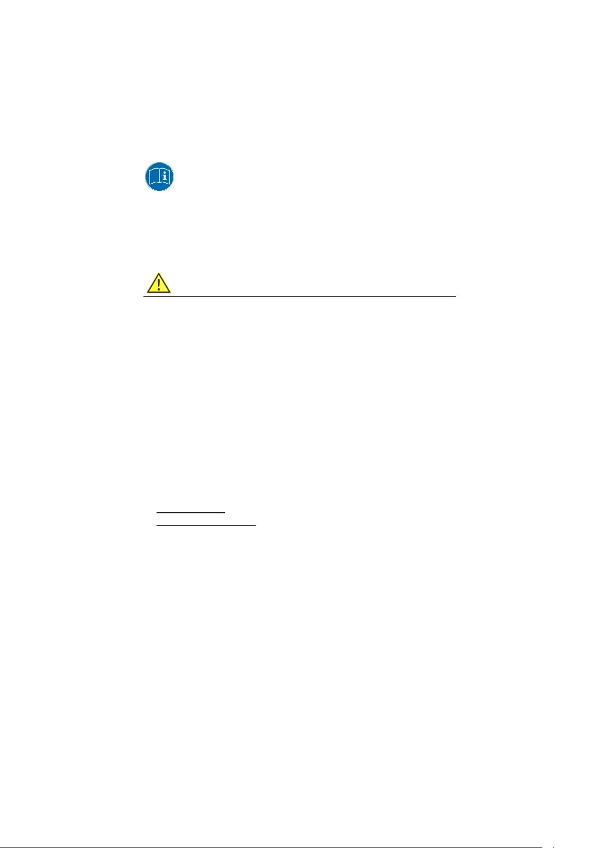
Contents For target group Availability
Safety instructions Important information
about protecting personnel
and property
Quick Start and
Installation Guide
Operating Instructions Complete operating
“DLoG Config” Manual,
etc.
Mounting instructions
for accessories
Pay attention to these manuals because they help avoid hazards, reduce repair costs and downtimes,
and increase the reliability and service life of the DLT-V72.
Keep the manuals for future use.
Please contact Advantech if you require additional information or clarification. You can find the contact
address in section Technical customer sup port.
First steps in
commissioning:
mechanical mounting and
electrical installation
instructions
Description of software for
the DLT-V72
Description of mounting
steps
Skilled personnel
Skilled personnel
Skilled personnel
and trained users
Skilled personnel
Skilled personnel
Printed, enclosed with
the device
PDF file at our
websites
1.1.1. Current manual versions at our websites
The latest versions of our manuals are available at our websites:
www.advantech.com
www.advantech-service-iot.eu
1.1.2. ONE manual for all device models
These operating instructions apply to all models of the DLT-V72 series:
− DLT-V7210 P (PCT)
− DLT-V7210 R (Resistive Touch)
− DLT-V7210 D (Defroster)
− DLT-V7212 P (PCT)
− DLT-V7212 R (Resistive Touch)
− DLT-V7212 D (Defroster)
− DLT-V7210 K (Integrated Keyboard)
− DLT-V7210 KD (Integrated Keyboard and Defroster)
− DLT-V7212 P+ (PCT)
DLT-V72 Operating Instructions V2.50 7 / 121
Page 18

Introduction
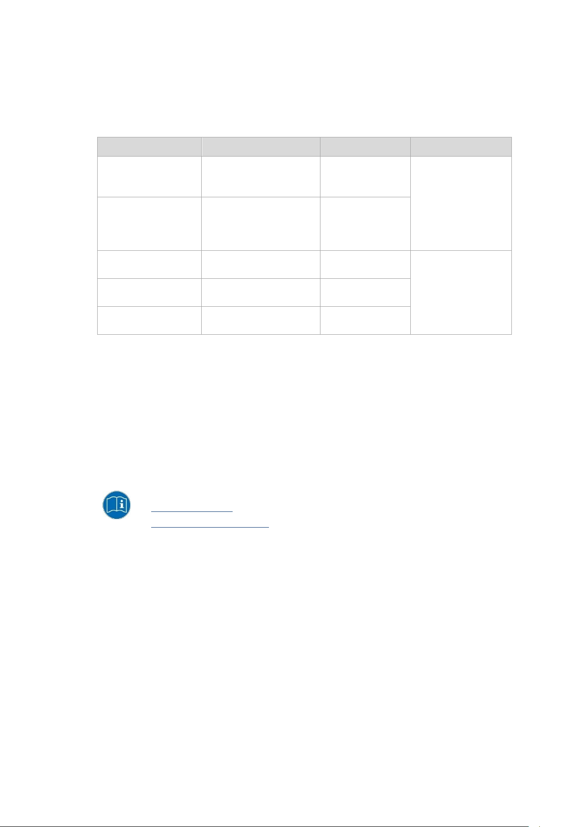
CAUTION means that slight bodily injury can occur if this information is not observed.
NOTICE: Property damage
Information about possible property damage.
Tips for using the product.
1.2. Warnings and notes in the operating instructions
Personal injury
Information with regard to personal injury is shown as follows (signal words for indicating risk level):
DANGER / WARNING / CAUTION
DANGER means that death or severe bodily injury will occur if this information is not observed.
WARNING means that death or severe bodily injury can occur if this information is not observed.
Property damage
Information about property damage is shown as follows:
Tips and notes
Tips and notes are shown as follows:
TIP
Note about additional information in manuals.
8 / 121 DLT-V72 Operating Instructions V2.50
Page 19

Technical customer support
2. Technical customer support
Contact your distributor, sales representative, or an Advantech Service Center for technical support.
Please have the following information ready:
− Product name
− Serial number
− Description of your peripheral attachments
− Description of your software (operating system, application softw are, etc.)
− The exact wording of any error messages
− A complete description of the problem
Find the contact data of our Global Advantech Service Centers on our website:
http://erma.advantech.com
DLT-V72 Operating Instructions V2.50 9 / 121
Page 20

Functional description
3. Functional description
3.1. Intended use
DLT-V72 Industrial Computers are data communication terminals for use in commercial industries such as
logistics, warehousing and manufacturing. Any other or additional use beyond this is regarded as improper use.
DLT-V72 Industrial Computers are only permitted to be opera ted:
− In accordance with the defined intended use.
− Within the usage limits and in accordance with the technical data.
− Observing the information in the documentation and in particular the safety and warning notices.
DLT-V72 Industrial Computers:
− Are not approved for use in explosion-hazard areas.
− Are not approved for use on ships and on rail vehicles.
− Are not approved for use in life-support systems or critical safety systems where system malfunction can
lead to the direct or indirect hazard of human life.
DLT-V72 Industrial Computers were designed and built according to modern technology and accepted safety
regulations. Improper use can result in injury to persons and in property damage, however, necessitating the
following:
− Correct transport, storage, commissioning and mainte nan ce as specified
− Operation by trained personnel
Accessories
Only use accessories that have been tested and certified for the respective DLT-V72. Otherwise, any warranty
for this device will be void.
Requirements for safe operation
− Proper transport and storage.
− Proper setup and use.
− Proper maintenance and service.
− Operation by trained personnel.
10 / 121 DLT-V72 Operating Instructions V2.50
Page 21

Functional description
3.2. Mount, operate and service the device correctly
DLT-V72 Industrial Computers were designed and built according to modern technology and accepted safety
regulations. However, the operation of the DLT-V72 can endanger personnel or third parties and cause damage
to the device and other material assets when, for example, the device is
− installed incorrectly or configured improperly.
− operated by untrained or uninstructed personnel.
− improperly operated and maintained.
− not used as intended.
The owner/operator commitments with regards to safety (accident prevention regulations, occupational safety)
are to be followed.
3.3. Device identification/name plate
The name plate on the rear side of the DLT-V72 must be legible at all times.
Do not damage the name plate or remove it from the device.
Information on the labels on the device (examples):
− Model name
− Serial number
− FCC ID (Radio)
− Barcode (for Advantech-internal use only)
DLT-V72 Operating Instructions V2.50 11 / 121
Page 22

Unpacking, transporting, storing
WARNING
4. Unpacking, transporting, storing
4.1. Packing list
Before setting up the system, check that the items listed below are included and in good condition. If any item
does not accord with the table, please contact your dealer immediately:
− DLT-V72 Industrial Computer
− Cable cover and cable sealing set
− Product supplement
− Possibly “OS End User License Agreement” (depends on optional OS type)
4.2. Unpacking
Open the packaging carefully to prevent damaging the device inside.
Save the packaging material (for possible forwarding transports or returns of the DLT-V72).
Check the shipment for completeness and any possible damage.
Always keep the supplied manuals and documents.
4.3. Transport
Risk of injury due to weight and sharp-edged parts.
The DLT-V72 can fall down and cause injuries due to its weight.
The strain relief rail can have sharp edges and cause cutting injuries.
Always hold the DLT-V72 by the housing with both hands.
Never use the antenna as a handle. It can break due to the weight involved.
Do not hold the DLT-V72 by the strain relief rail.
Use the assistance of a second person for installation work.
12 / 121 DLT-V72 Operating Instructions V2.50
Page 23

Unpacking, transporting, storing
WARNING
NOTICE: Property damage
4.4. Storage
Observe the permissible storage temperature range in the manual, section
5.2 Environmental conditions.
Observe the “DLT-V72 Safety Instructions” regarding DLT-V72 devices with integrated UPS.
Personal injury due to short-circuit, fire, chemical burns, toxic substances.
Devices with integrated UPS (optional) contain lithium-ion battery packs. These can ignite if handled or
stored improperly (risk of fire), cause chemical burns or release toxic substances.
Use care when handling lithium-ion battery packs.
Do not damage lithium-ion battery packs; do not drill through and do not crush or drop.
Store lithium-ion battery packs separate ly from acids and oth er materia ls.
Store the DLT-V72 and accessories in a cool and dry location and comply with the specified storage
temperature and air humidity.
Provide for sufficient ventilation of the storage location.
Do not allow water or other liquids to come into contact with the device (exercise particular caution with
corrosive liquids).
Do not store the device near sources of heat or fire, open flames or heaters.
Do not allow it to come into contact with fire.
Have suitable fire extinguishers ready (foam or powder) in accordance with safety regulations.
Prevent deep discharge
Deep discharge of the battery pack due to incorrect storage.
Storing the battery packs incorrectly will cause them to discharge completely (deep discharge) and thus
damage them irreparably.
To prevent a deep discharge:
Remove the battery pack from the battery pocket, if the DLT-V72 is not used for a longer period of time
(more than one month).
Charge the battery pack in the DLT-V72 device every six months.
Protecting touchscreens during storage
Protect touchscreens from sharp edges, impacts, and heavy objects.
If stacking, do not stack higher than four devices.
Place devices front-to-front in this case.
The VESA mounting point on the rear side of the device can damage the touchscreen of another device.
Use protective material (non-flammable!) between the devices as a precaution.
DLT-V72 Operating Instructions V2.50 13 / 121
Page 24

Technical data – Device
5. Technical data – Device
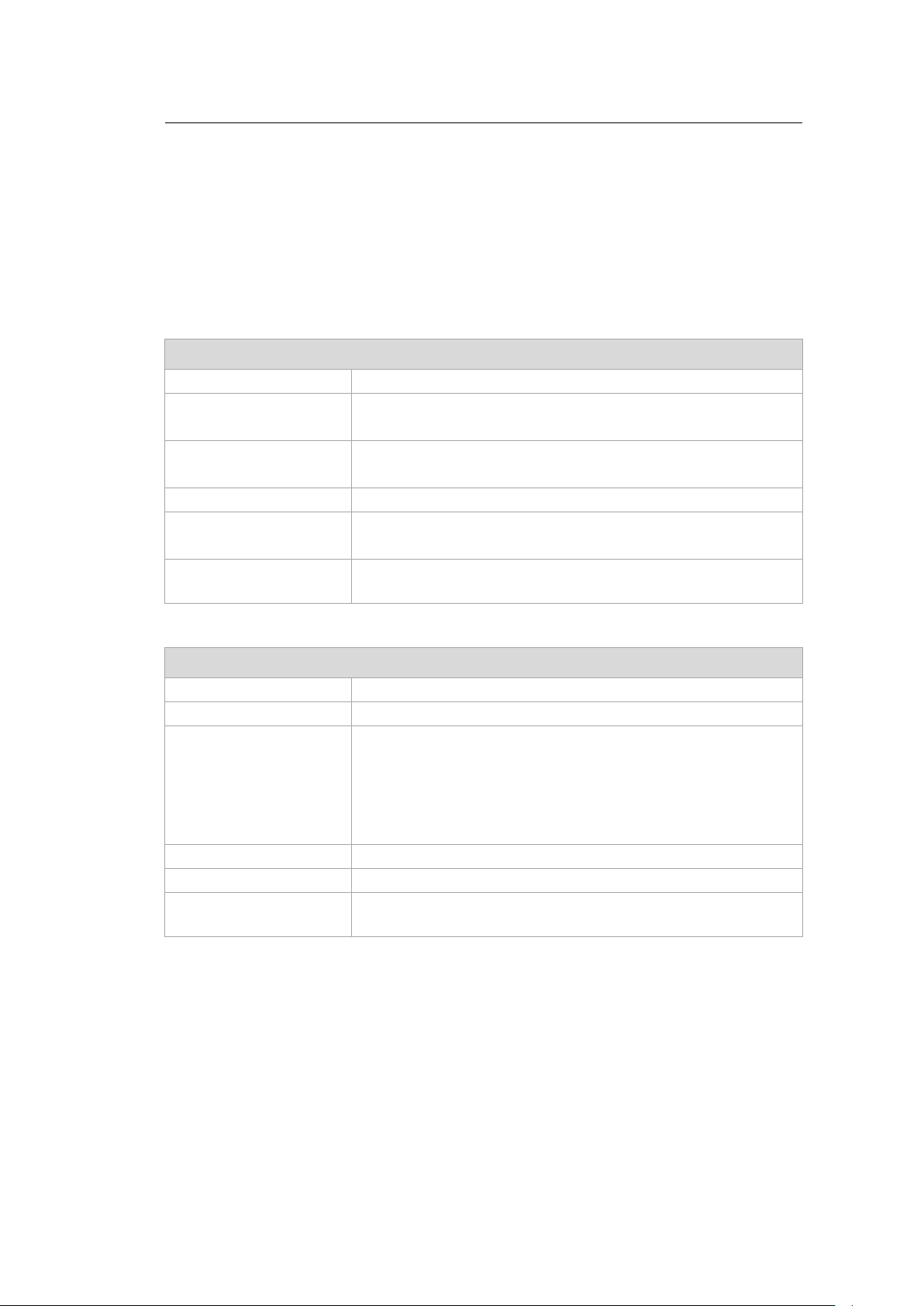
5.1. General
CPU
Chipset
Cache
RAM 4 GB RAM
BIOS AMI Aptio UEFI; ACPI 5.0 compliant
Real-time clock Real-time clock with a power reserve of up to 5 years
CFast 4 GB and more CFast memory card
Weight (without accessories, antenna, battery pack), material
DLT-V7210 P
DLT-V7210 R
DLT-V7210 D
DLT-V7212 P
DLT-V7212 R
DLT-V7212 D
DLT-V7210 K
DLT-V7210 KD
DLT-V7212 P+ Approx. 3.7 kg
Battery pack Approx. 0.15 kg
Material Rugged aluminum-cast housing, ESD safe
Intel® ATOM™ E3845 Quad Core 1.91 GHz Processor
Dual channel 1333 MHz memory bus speed
2 MB L2 cache, 22 nm
DDR3L Technology
Approx. 3.6 kg
Approx. 4.6 kg
Approx. 3.7 kg
Display
DLT-V7210 10.4" XGA color TFT
1024 x 768 resolution
400 cd/m² brightness
DLT-V7212 12.1" XGA color TFT
1024 x 768 resolution
500 cd/m² brightness
DLT-V7210 K
DLT-V7210 KD
DLT-V7212 P+ 12.1" XGA color TFT
The LCD display of the DLT-V72 series fulfills the highest quality standards and was inspected for pixel defects.
However, due to technological reasons pixel defects can occur.
This is not a malfunction; it is a part of the technical specifications.
10.1" widescreen WXGA color TFT
1280 x 800 resolution
500 cd/m² brightness
1024 x 768 resolution
600 cd/m² brightness
14 / 121 DLT-V72 Operating Instructions V2.50
Page 25
Technical data – Device
NOTICE: Property damage
Protect the display of the DLT-V72 from the memory effect.
The display of the DLT-V72 has to be protected from the burning in of a motionless image. An image
that has remained motionless for too long can cause irreversible damage to the display.
Recommendation:
Use a screensaver.
In the power management, set the display to turn off when there is no user input.
Resistive touchscreen
Type 5-wire analog resistive touchscreen
Construction Film-Film-Glass (FFG)
Fully laminated front
Surface Hardness JIS-K-5400: 2H/3H at 750 g
Chemically hardened glass
Resistance Shock resistance IK08
Mechanical resistance Tapping: > 1 million times with rubber test pen
Swiping: > 100,000 times with polydactyl pen
Chemical resistance Alcohols, Dilute Acids, Dilute Alkalis, Esters, Hydrocarbons, Ketones,
Household Cleaning agents (according to DIN 42 115)
Projected-capacitive touchscreen (PCT)
Type Projected-capacitive touchscreen
Construction Glass film
Surface Hardness JIS-K-5400: > 10 H at 750 g
Resistance Shock resistance IK08
Mechanical properties Thermally pre-stressed, acid-frosted float glass
Chemical resistance Alcohols, Dilute Acids, Dilute Alkalis, Esters, Hydrocarbons, Ketones,
Internal speaker, sound
The DLT-V72 is equipped with an internal speaker as standard (2 W).
The system messages from the industrial PC are output via this speaker.
The internal speaker is configured in the audio sett ing s for th e operatin g syst em in que stio n .
Chemical AR coated glass:
− DLT-V7210 P and DLT-V7212 P gloss value 85 at 60°
− DLT-V7210 K, KD and DLT-V7212 P+ gloss value 70 at 60°
(according to ISO 2813, 7668; ASTM D 523, D 2457; DIN 67539)
Household Cleaning agents (according to DIN 42 115)
DLT-V72 Operating Instructions V2.50 15 / 121
Page 26

Technical data – Device
DLT-V7210 KD
DLT-V7210 KD
5.2. Environmental conditions
5.2.1. DLT-V72 without integrated UPS
Operating temperature -30 to +50 °C
Specification according to EN 60068-2-1/2
Storage temperature -30 to +65 °C
Specification according to EN 60068-2-1/2
Relative humidity 10% to 90% at 40 °C relativ e h umid ity
Noncondensing
Specification according to EN 60068-2-3
Mechanical vibration
and shock resistance
IP protection class IP65 and IP66 for:
Class 5M3 according to EN 60721-3-5
US Highway Truck according to MIL-STD 810F
− DLT-V7210
− DLT-V7212
− DLT-V7212 P+
IP65 for:
− DLT-V7210 K
−
5.2.2. DLT-V72 with integrated UPS (optional)
Operating temperature -30 to +50 °C
Specification according to EN 60068-2-1/2
Storage temperature -30 to +60 °C
Specification according to EN 60068-2-1/2
Charging temperature -10 to +50 °C (ambient temperature)
Relative humidity 10% to 90% at 40 °C relativ e h umid ity
Noncondensing
Specification according to EN 60068-2-3
Mechanical vibration
and shock resistance
IP protection class IP65 and IP66 for:
Class 5M3 according to EN 60721-3-5
US Highway Truck according to MIL-STD 810F
− DLT-V7210
− DLT-V7212
− DLT-V7212 P+
IP65 for:
− DLT-V7210 K
−
16 / 121 DLT-V72 Operating Instructions V2.50
Page 27
Technical data – Device
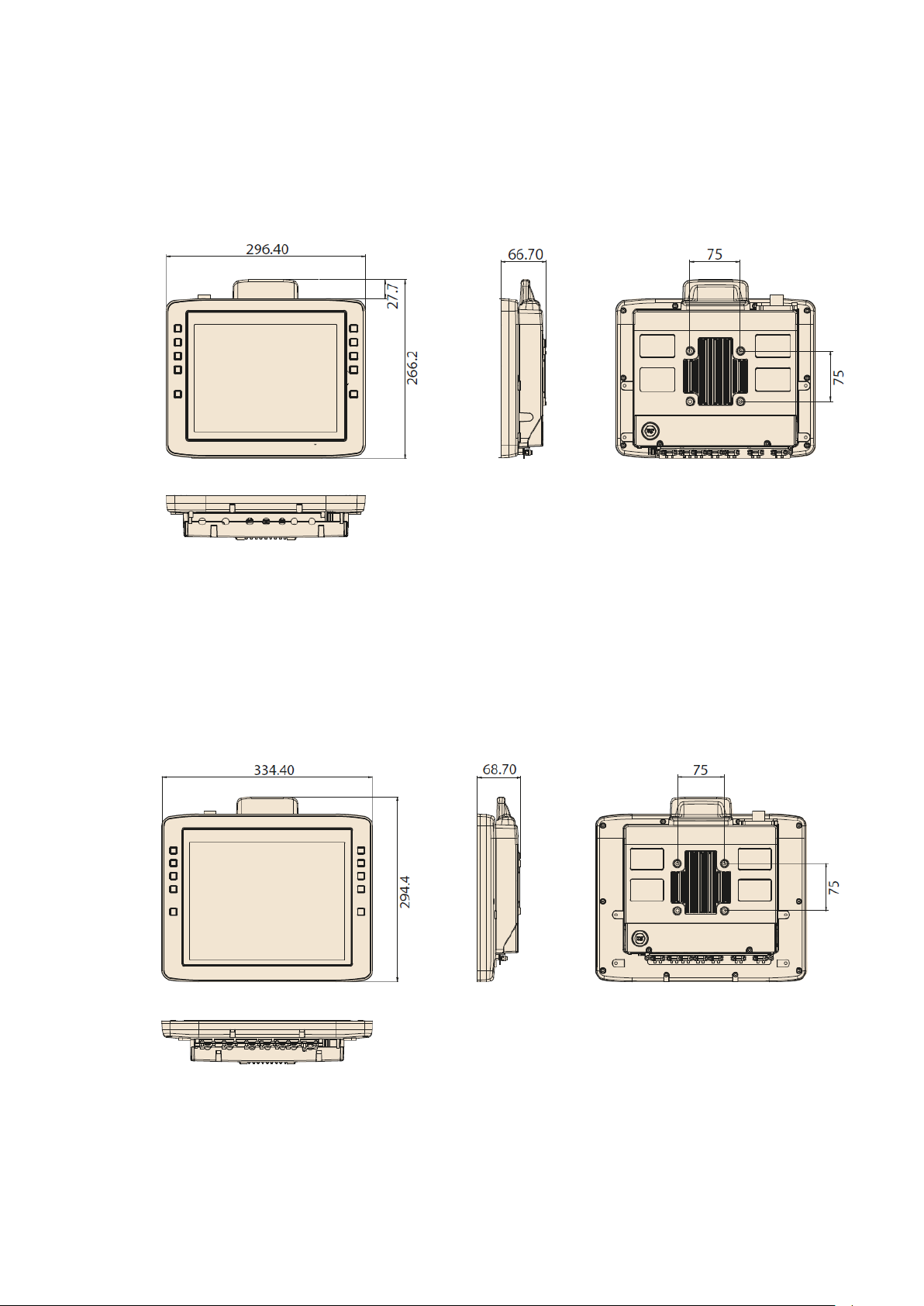
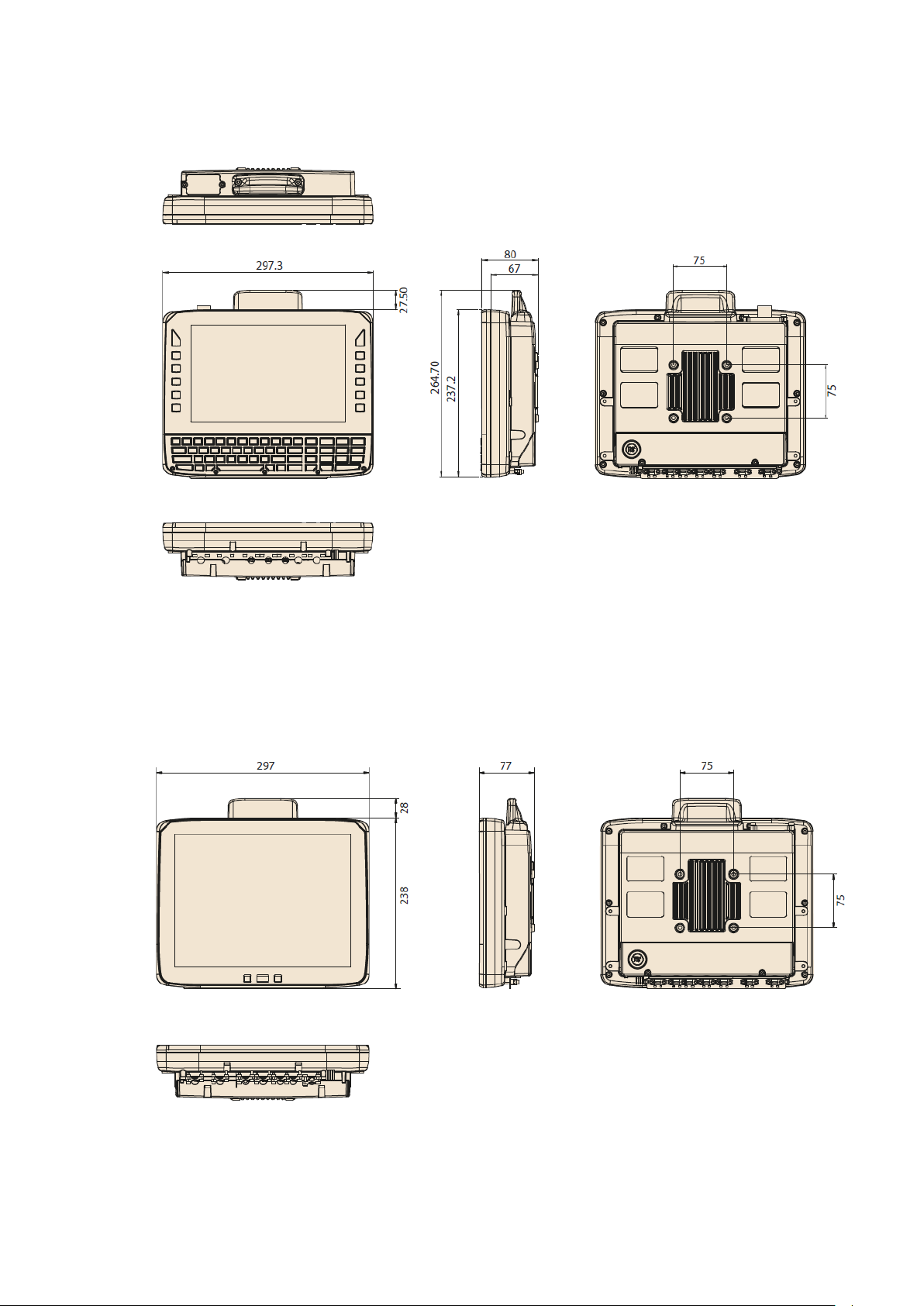
5.3. Device dimensions
5.3.1. DLT-V7210 P, R, D
Dimensions without add-ons (in mm)
Fig. 5.1: Dimensions DLT-V7210 P, R, D
5.3.2. DLT-V7212 P, R, D
Dimensions without add-ons (in mm)
Fig. 5.2: Dimensions DLT-V7212 P, R, D
DLT-V72 Operating Instructions V2.50 17 / 121
Page 28
Technical data – Device
5.3.3. DLT-V7210 K, KD
Dimensions without add-ons (in mm)
Fig. 5.3: Dimensions DLT-V7210 K, KD
5.3.4. DLT-V7212 P+
Dimensions without add-ons (in mm)
18 / 121 DLT-V72 Operating Instructions V2.50
Fig. 5.4: Dimensions DLT-V7212 P+
Page 29

Technical data – Device
NOTICE: Property damage
Otherwise, any warranty for this device will be void.
5.4. VESA drill holes
The back of the DLT-V72 has a VESA-compatible 75 x 75 mm mounting hole pattern. It is used to attach VESAcompatible mountings to mount the DLT-V72 at the deployment location.
Depth of thread: M6 x 6m m
Only use mountings and mounting material s that hav e been tested and approved for the respective DLT-V72.
Mounting
Please observe the mounting information in manual chapter:
12.4.1 VESA mounting hole pattern
DLT-V72 Operating Instructions V2.50 19 / 121
Page 30
Technical data – Radio modules (optional)
and its authorized service centers may open the device and install / r emove it.
6. Technical data – Radio modules (optional)
6.1. Identification of the equipment variants
The DLT-V72 offers numerous radio equipment variants for WLAN, WWAN, GNSS and Bluetooth.
To identify the variant installed in your device, proceed as follows:
− Read off the FCCID on the device name plate/label and compare with the technical data on the following
pages.
− Open the Device Manager to determine the name of the radio card, for example.
The radio equipment variants for WLAN, WWAN, GNSS and Bluetooth are available as options and are not
included in the standard scope of delivery of the DLT-V72.
6.2. Radio cards (optional)
NOTICE: Property damage
DLT-V72 may only be operated with the radio modules described in the following section.
Radio cards are located inside the devices and are not accessible from the outside. Only the manufacturer
6.2.1. Radio card for WLAN
SPARKLAN WPEQ-261ACN(BT)
Card type WLAN PCIe Half-Mini Card
Technology WLAN IEEE802.11 a/b/g/n/ac and Bluetooth
FCCID RYK-261ACNBT
IC ID 6158A-261ACBT
Band 1: WLAN 2.4 GHz
Frequency range 2400 to 2485 MHz
Frequency band ETSI Europe 2.4 GHz to 2.483 GHz
Channels available 1 to 13
Supported standards WLAN IEEE802.11 a/b/g/n/ac and Bluetooth
Maximum TX power 100 mW / 20 dBm
Band 2: WLAN 5 GHz
Frequency range 5150 to 5875 MHz
Frequency band ETSI Europe 5.15 GHz to 5.35 GHz
Channels available 36 to 165
Supported standards WLAN IEEE802.11 a/b/g/n/ac
Maximum TX power 100 mW / 20 dBm
(both supported via a single antenna)
(both supported via a single antenna)
5.47 GHz to 5.725 GHz
20 / 121 DLT-V72 Operating Instructions V2.50
Page 31

Technical data – Radio modules (optional)
6.2.2. Radio card for WWAN
USA: QUECTEL EC25A
Europe: QUECTEL EC25E
Card type WWAN PCIe Full-Mini Card
Technology WWAN 2G, 3G, 4G cellular bands and GNSS
FCCID FCC ID: XMR201605EC25A
Maximum transmitting power Class 3 (23dBm±2dB) for LTE FDD
(valid for the EC25-A variant)
Class 3 (23dBm±2dB) for LTE TDD
Class 3 (24dBm+1/-3dB) for TD-SCDMA
Class 3 (24dBm+1/-3dB) for WCDMA
Class E2 (27dBm±3dB) for EDGE 850/900MHz
Class E2 (26dBm+3/-4dB) for EDGE 1800/1900MHz
Class 4 (33dBm±2dB) for GSM 850/900MHz
Class 1 (30dBm±2dB) for GSM 1800/1900MHz
DLT-V72 Operating Instructions V2.50 21 / 121
Page 32
Technical data – Radio modules (optional)
6.3. Antennas (optional)
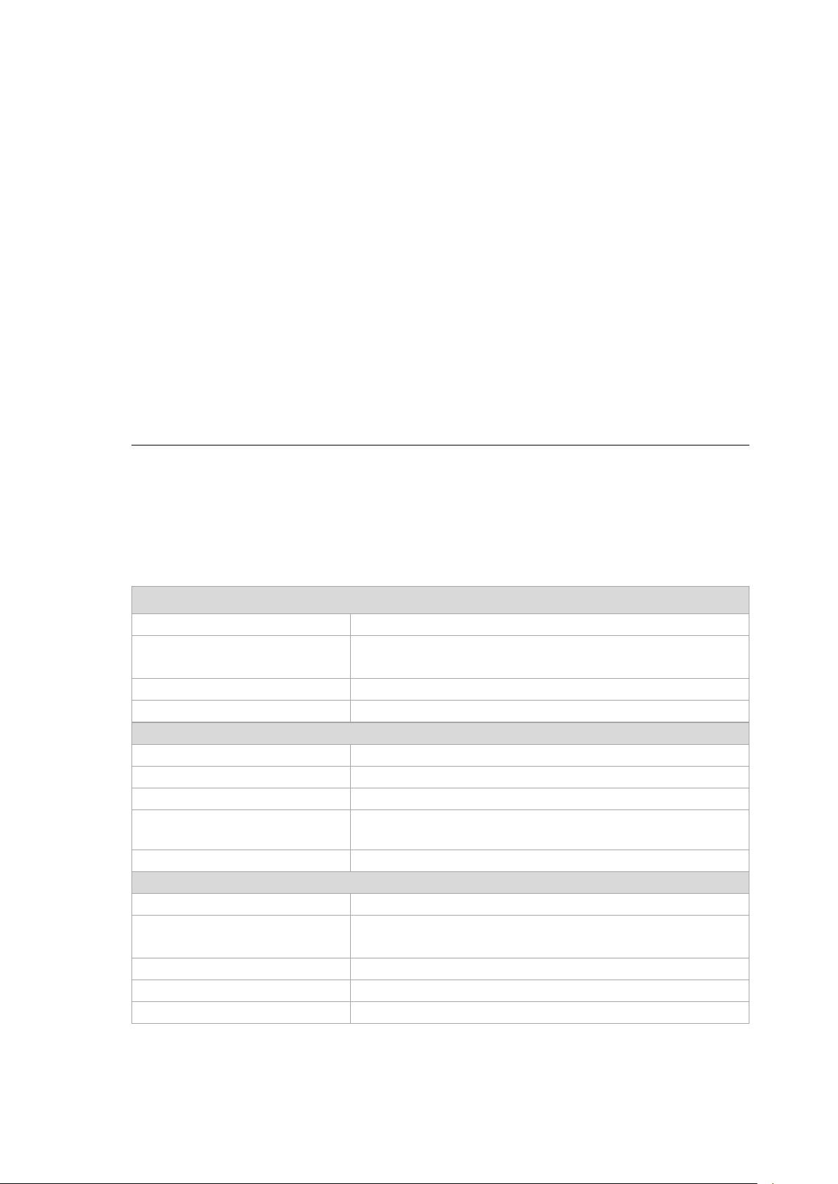
6.3.1. WLAN antenna IEEE 802.11 a/b/g/n/ac
Fig. 6.1: WLAN antenna IEEE 802.11 a/b/g/n/ac
Technical data
Application WLAN a/b/g/n/ac Dual Band with MRC
WLAN frequency range Band 1: 2400 to 2485 MHz
Bluetooth features
Number of antennas 2
Available color Red
Type Omnidirectional antenna
Antenna gain Max. 4.44 dBi (without loss through the cable)
Impedance 50 Ω
Polarization Vertical/horizontal
Maximum transmitting power 100 mW / 20 dBm
Compatible Radio card: SPARKLAN WPEQ-261ACN(BT)
Bluetooth (integrated via Radio card)
Band 2: 5150 to 5850 MHz
See section 6.4.1 Bluetooth
(see section 6.2.1 Radio card)
22 / 121 DLT-V72 Operating Instructions V2.50
Page 33

Technical data – Radio modules (optional)
6.3.2. WLAN, WWAN, LTE 4G antenna (Multiband)
Fig. 6.2: WLAN, WWAN, LTE 4G antenna (Multiband)
Technical data
Application WLAN IEEE 802.11 ac/a/b/g/n Dual Band with MRC
WWAN 4G
Bluetooth 4.2+HS
WLAN frequency range Band 1: 2400 to 2485 MHz
Band 2: 5150 to 5875 MHz
WWAN frequency bands
with EC25-E
FDD LTE: B1/B3/B5/B7/B8/B20
TDD LTE: B38/B40/B41
WCDMA: B1/B5/B8
GSM: 900/1800
WWAN frequency bands
with EC25-A
Bluetooth features
FDD LTE: B2/B4/B12
WCDMA: B2/B4/B5
See section 6.4.1 Bluetooth
Number of antennas 4
Available color Red
Type Omnidirectional antenna
Antenna gain WLAN: Max. 5.8 dBi
WWAN: Max. 3.5 dBi
Impedance 50 Ω
Polarization Vertical/horizontal
Maximum transmitting power WLAN: 100 mW / 20 dBm
WWAN:
Class 3 (23dBm±2dB) for LTE FDD
Class 3 (23dBm±2dB) for LTE TDD
Class 3 (24dBm+1/-3dB) for TD-SCDMA
Class 3 (24dBm+1/-3dB) for WCDMA
Class E2 (27dBm±3dB) for EDGE 850/900MHz
Class E2 (26dBm+3/-4dB) for EDGE 1800/1900MHz
Class 4 (33dBm±2dB) for GSM 850/900MHz
Class 1 (30dBm±2dB) for GSM 1800/1900MHz
Compatible WLAN card: SPARKLAN WPEQ-261 ACN (BT)
(see section 6.2.1 Radio card)
Compatible WWAN card: USA: QUECTEL EC25A
Europe: QUECTEL EC25E
(see section 6.2.2 Radio card)
DLT-V72 Operating Instructions V2.50 23 / 121
Page 34
Technical data – Radio modules (optional)
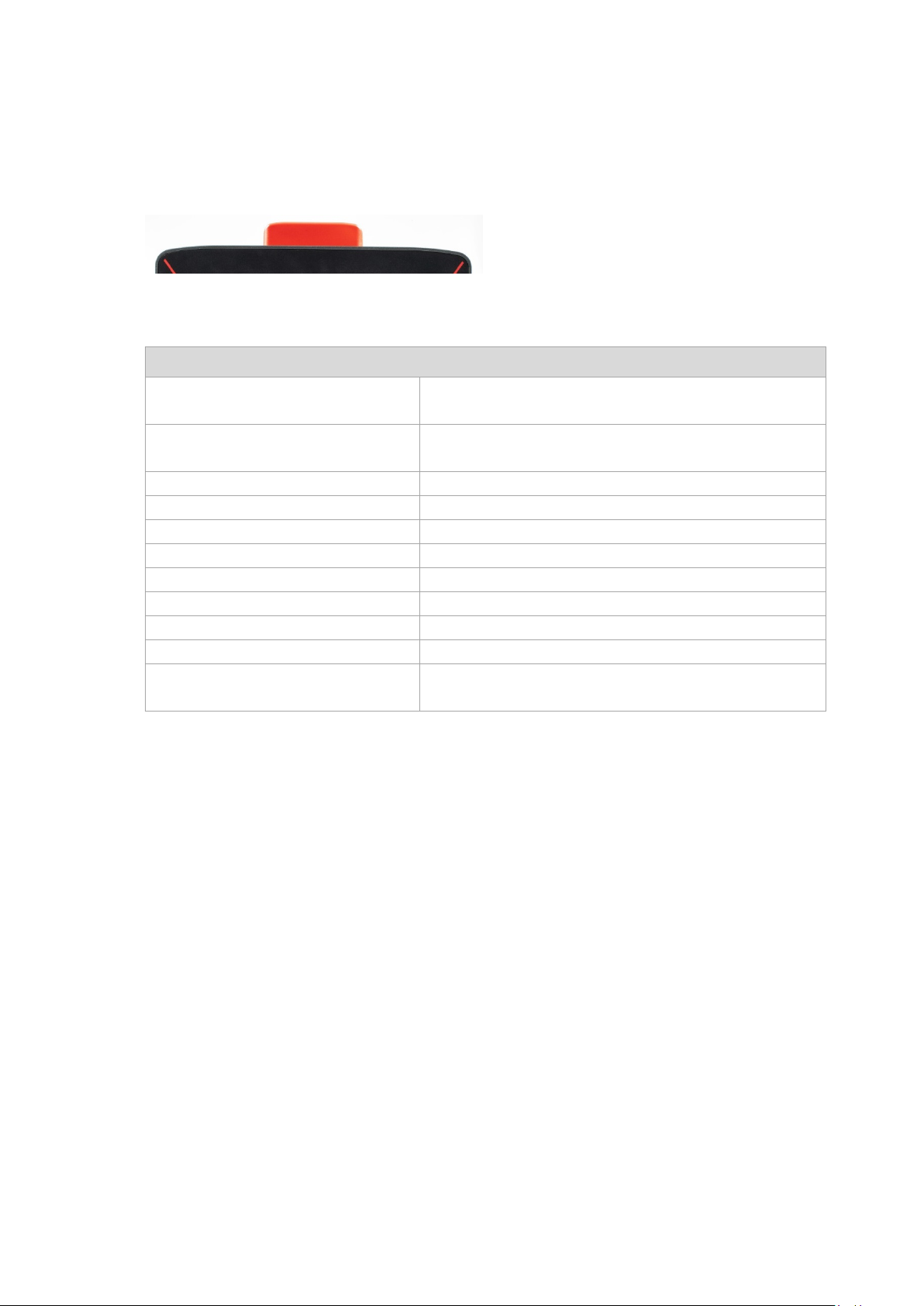
6.3.3. External WLAN antenna IEEE 802.11 a/b/g/n
Fig. 6.3: External WLAN antenna
Technical data
Application WLAN IEEE 802.11 a/b/g/n Dual Band
Mounting location For detached mounting, e.g. on the roof of the forklift
WLAN frequency range Band 1: 2400 to 2485 MHz
Number of antennas 1
Type Omnidirectional antenna
Antenna gain Band 1: Max. 4 dBi (without loss through the cable)
Impedance 50 Ω
Polarization Vertical/horizontal
Dimensions Ø 86 x 43 mm (Ø 3.39” x 1.69”)
Weight 0.3 kg (0.66 lbs)
Connector labeling N-type or TNC N, Jack, female, bottom
Scope of delivery 3 m antenna cable
Maximum transmitting power 100 mW / 20 dBm
Corresponding WLAN radio card: SPARKLAN WPEQ-261 ACN (BT)
Band 2: 5150 to 5875 MHz
Band 2: Max. 6.5 dBi (without loss through the cable)
RSMA plug for RSMA socket on the terminal
(see section 6.2.1 Radio card)
24 / 121 DLT-V72 Operating Instructions V2.50
Page 35

Technical data – Radio modules (optional)
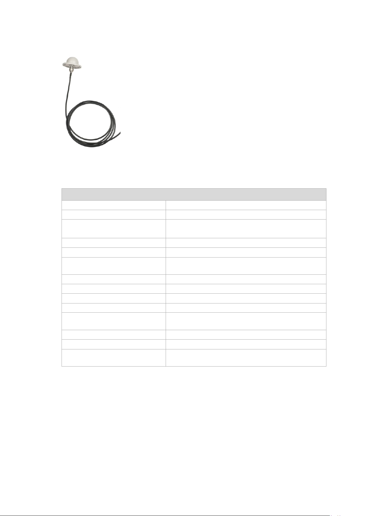
6.3.4. External WWAN antenna 2G, 3G, 4G
Fig. 6.4: External 2G, 3G, 4G WWAN antenna
Technical data
Application WWAN 2G, 3G, 4G cellular bands
Mounting location For detached mounting, e.g. on the roof of the forklift
Number of antennas 1
Type Omnidirectional antenna
Antenna gain Typically 2.2 dBi
Impedance 50 Ω
Polarization Vertical
Dimensions Height 79.45 mm
Cable length 3 m
IP protection IP67 and IP69K
Max. transmitting power
of antenna
Compatible WWAN card: USA: QUECTEL EC25A
Diameter 42 mm
Class 3 (23dBm±2dB) for LTE FDD
Class 3 (23dBm±2dB) for LTE TDD
Class 3 (24dBm+1/-3dB) for TD-SCDMA
Class 3 (24dBm+1/-3dB) for WCDMA
Class E2 (27dBm±3dB) for EDGE 850/900MHz
Class E2 (26dBm+3/-4dB) for EDGE 1800/1900MHz
Class 4 (33dBm±2dB) for GSM 850/900MHz
Class 1 (30dBm±2dB) for GSM 1800/1900MHz
Europe: QUECTEL EC25E
(see section 6.2.2 Radio card)
DLT-V72 Operating Instructions V2.50 25 / 121
Page 36

Technical data – Radio modules (optional)
6.4. Bluetooth
6.4.1. Bluetooth integrated
Requirement: Use of the radio card SPARKLAN WPEQ-261ACN (BT)
Technical data
Type Blueto ot h 4.2+HS
Standards V4.2, V4.0 LE, V3.0+HS, V2.1+EDR
Transmission rate 1 Mbps, 2 Mbps, up to 3 Mbps
6.5. GPS receiver external (optional)
With the optional GPS receiver the DLT-V72 can be used for GPS navigation.
The GPS receiver has an integrated antenna for position data of the Global Positioning System (GPS) and
communicates with the DLT-V72 via USB interface.
We recommend using only a GPS receiver approved by Advantech.
Fig. 6.5: External GPS receiver (optional)
Installation
The installation CD supplied with the GPS receiver includes installation files and a multi-lingual manual.
Please read the additional information in the manual about the GPS receiver.
Fig. 6.6: Ext. GPS receiver, display example during installation
26 / 121 DLT-V72 Operating Instructions V2.50
Page 37

Connectors
7. Connectors
7.1. Connectors under the cable cover
Fig. 7.1: External connectors under the cable cover
Pin assignment
Power supply 12/24/48 VDC nominal
1 x SMA (optional) Remote WWAN antenna
1 x RSMA (optional) Remote WLAN antenna
USB0, USB1, USB2, USB3 USB 2.0 interfaces (HI-SPEED™), bootable
Fused at 1.0 A per channel
ESD Level 4 protected (according to EN 61000-4-2)
RJ45 LAN Ethernet 10/100/1000 MBit/s
COM1, COM2 Serial interfaces
Max. 115,200 Baud (16550A compatible, 16 byte FIFO),
supports EIA-232-E on external 9-pin D-Sub con nection
ESD Level 4 protected (according to EN 61000-4-2)
7.1.1. COM1 as a voltage source
The COM1 interface can optionally supply to externally connected equipment with +5 VDC.
The voltages are protected by internal fuses and may not exceed a continuous consumed current
of 1 A at 5 V.
Depending on the connected devices, the maximum current consumption may be significantly lower.
Using the “DLoG Config” tool, you can select whether +5 VDC or RI is output on pin 9 of COM1.
DLT-V72 Operating Instructions V2.50 27 / 121
Page 38

Connectors
Left LED (green):
Right LED (orange):
LED off: no connection
LED off: no activity
LED on: connection (link)
LED flashing: activity
7.1.2. Network adapter (10/100/1000)
The DLT-V72 is equipped with a 10/100/1000 Mbit network adapter with 10/100/1000 Mbit per second.
This adapter can be accessed via the bottom of the device and offers an RJ45 connection jack.
The RJ45 connection port has two integrated status LEDs and are assigned as follows:
Fig. 7.2: RJ45 network port
Problems with data transmission via LAN/Ethernet
If problems occur during data transmission over LAN/Ethernet (e.g. data is lost or not detected), the cause of
these problems may be a cable which is too long. Depending on the cable layout and interference from the
environment, it may be impossible to use the cable length of 100 m given in the specification (IEEE 802.3
standard). The solution here is the use of a shorter cable.
28 / 121 DLT-V72 Operating Instructions V2.50
Page 39

Connectors
NOTICE: Property damage
Hold cards and sticks securely and carefully, and insert precisely into the connections to avoid anything
sealed again; only then is the protection class guaranteed.
7.2. Connectors under the antenna or protective cap
The following connectors can be found under the DLT-V72 antenna or under the protective cap (for devices
without radio equipment):
− Service-USB (USB 3.0 Host, SUPERSPEED
− CFast-Slot
− Mini-SIM card slot (optional)
− Antennas or protective caps are only permitted to be removed by qualified expert personnel and only
for the duration of servicing work.
− Switch off the DLT-V72 before removing the antenna or protective cap.
− No objects or liquids are permitted to enter the opened DLT-V72.
− Insert/remove cards and sticks when the device has been fully deenergised.
−
falling inside the device
− The device is only permitted to be operated again once the protective cap or antenna is pro perly
TM
)
7.3. Open/close the protective cap
Tool required: 3mm Allen wrench
Open protective cap:
Unfasten both screws on the protective cap.
Remove the protective cap from the device.
The interfaces are now accessible.
Close protective cap:
Place the protective cap back onto the DLT-V72.
Tighten both screws (1 Nm torque).
DLT-V72 Operating Instructions V2.50 29 / 121
Page 40

Connectors
7.4. Open/close the WLAN antenna IEEE 802.11 a/b/g/n/ac
Tools required:
− Torx screwdriver, Tx20
− Allen key (size 7)
Opening the antenna cap:
Unfasten both screws on the antenna cap.
Remove the antenna cap from the device.
Fig. 7.3: WLAN antenna IEEE 802.11 a/b/g/n/ac opened
Closing the antenna cap:
Place the antenna back onto the DLT -V72.
Tighten both screws (1 Nm torque).
30 / 121 DLT-V72 Operating Instructions V2.50
Page 41
Connectors
NOTICE: Property damage
radio operation is no longer guaranteed.
7.5. Open/close the WLAN, WWAN, LTE 4G antenna
Tools required:
− Torx screwdriver, Tx20
− Allen key (size 7)
Opening the antenna cap:
Unfasten both screws on the antenna.
Remove the antenna carefully.
The antenna module is located underneath the antenna cap:
Fig. 7.4: Open WLAN, WWAN LTE 4G antenna
Removing the antenna module:
Unfasten both screws on the antenna module.
Remove the antenna module extremely carefully.
− Remove the antenna module extremely carefully from the device, as it is secured using thin
connection cables onto the Radio card(s) in the interior of the device.
− The connection cables can be detached from the antenna module and the radio card, meaning
Fasten antenna module and antenna cap:
Place the antenna module back onto the DLT-V72.
Take care not to pinch or damage the connection cables when doing this.
Tighten the two bolts again (1 Nm torque).
Place the antenna cap back onto the DLT-V72.
Tighten the two screws of the antenna cap again (1 Nm torque).
DLT-V72 Operating Instructions V2.50 31 / 121
Page 42

Operation
8. Operation
8.1. Safety during ongoing work operations
WARNING
Personal injury, Property damage and downtimes due to improper operation
Requirements for the operating personnel
Users of the DLT-V72 must be trained by skilled personnel and instructed in the operation of the device. All
users must be familiar with all functions of the product they come into contact with.
General
Do not use the DLT-V72 in explos ion haz ard ar ea s.
Switch off the DLT-V72 if located in the vicinity of petrol stations, fuel depots, chemical plants, etc.
Switch off the DLT-V72 before using the interfaces undern eath the antenna.
Switch off the DLT-V72 before replacing the battery pack.
Ensure that the deployment location of the DLT-V72 complies with the permissible environmental
conditions.
The following applies when using the DLT-V72 on vehicles:
The vehicle driver is not permitted to operate the DLT-V72 while driving. Operating the device can
represent a distraction from driving operations and there is an increased risk of accident.
The DLT-V72 must be disconnected from the vehicle battery while the vehicle battery is being charged.
Or it must be ensured that the maximum permitted input voltage of the DLT-V72 is not exceeded.
Deployment location fueling stations, chemical plants.
The operation of electrical equipment at locations where flammable gases or vapors are present pos es a safety
hazard.
Turn off the DLT-V72 when you are near gas stations, fuel depots, chemical plants or places where
blasting operations take place.
32 / 121 DLT-V72 Operating Instructions V2.50
Page 43

Operation
WARNING
8.2. Switching the DLT-V72 on/off
The following factors determine how the DLT-V72 can be switched on and off:
− Is the DLT-V72 mounted on a vehicle and connected with the ignition signal?
− What are the automatic shutdown settings that were defined in the “DLoG Config” program?
Switch on
Switch the DLT-V72 on as follows, depending on the configuration:
Press the <Power> button.
Or: By applying the supply voltage.
Or: Through the ignition signal of the vehicle (depends on automatic shutdown settings).
Switch off
Switch the DLT-V72 off as follows, depending on the configuration:
Press the <Power> button of the activated DLT-V72.
Or: Disconnect the supply voltage.
NOTICE: Devices without integrated UPS will be hard-terminated (data loss possible).
Devices with integrated UPS will switch automatically to UPS/battery power supply when the supply
voltage is broken.
Or: Deactivate the ignition of the connected vehicle (depends on automatic shutdown settings).
Electric shock due to incomplete switching off of the DLT-V72 with integrated UPS.
Because of the lithium-ion battery pack, the integrated UPS may still carry current even if the DLTV72 itself is switched off.
Reason: If the DLT-V72 has been configured to also start without <Power> button and ignition in the
"DLoG Config" program, this setting will need to be changed first. Otherwise, the DLT-V72 will restart
after a short pause as long as there is available battery capacity.
Shut down the DLT-V72 via the operating system function.
Disconnect from the power supply.
Open the battery cover; unp lu g the batt ery pack.
Time between switching off and on: 10 seconds
After the DLT-V72 has been shut down and switched off, it takes 10 seconds until the device will react to a
switch-on signal (<Power> button / ignition).
DLT-V72 Operating Instructions V2.50 33 / 121
Page 44

Operation
NOTICE: Property damage
Salt water on the PCT touchscreen can be interpreted as a "touch" and lead to malfunctions.
8.3. Operating the touchscreen
All touchscreens can be operated with:
− Clean, dry fingers
− Clean, dry gloves
− Suitable touch stylus:
Resistive touchscreens: t ouc h sty lus plastic or wood, rounded tip
PCT touchscreens: touch stylus with capacitive (electrically condu ctiv e) tip
Prevent damage to the touchscreen
Valid for all touchscreen versions: Resistive and PCT!
Keep the touchscreen clean.
Do not touch the touchscreen with pointed, sharp, rough or hard objects, e.g. ball point pens, writing
implements, tools of any kind (e.g. screwdrivers).
Make sure that no adhesives get on the surface of the touchscreen.
Ensure that the screen surface is not influenced by high voltages or static electricity.
Do not use excessive force when touching touchscreens, do not hit or press hard.
If the device with the touchscreen is placed down: Place a clean, soft cloth underneath.
Multi-touch capability
Depending on the installed operating system type, the PCT touchscreen of the DLT-V72 is multi-touch capabl e.
This means it can detect two touches simultaneous ly .
34 / 121 DLT-V72 Operating Instructions V2.50
Page 45
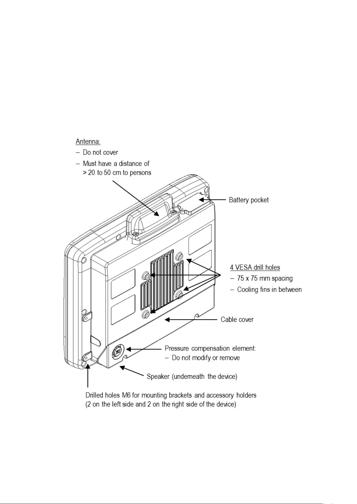
Operation
8.4. Operation elements
8.4.1. Note on the backlight function on/off
The DLT-V72 will continue to react to keyboard, mouse and touchscreen inp uts ev en if the backlight is sw itched
off.
8.4.2. Rear side
DLT-V72 Operating Instructions V2.50 35 / 121
Page 46
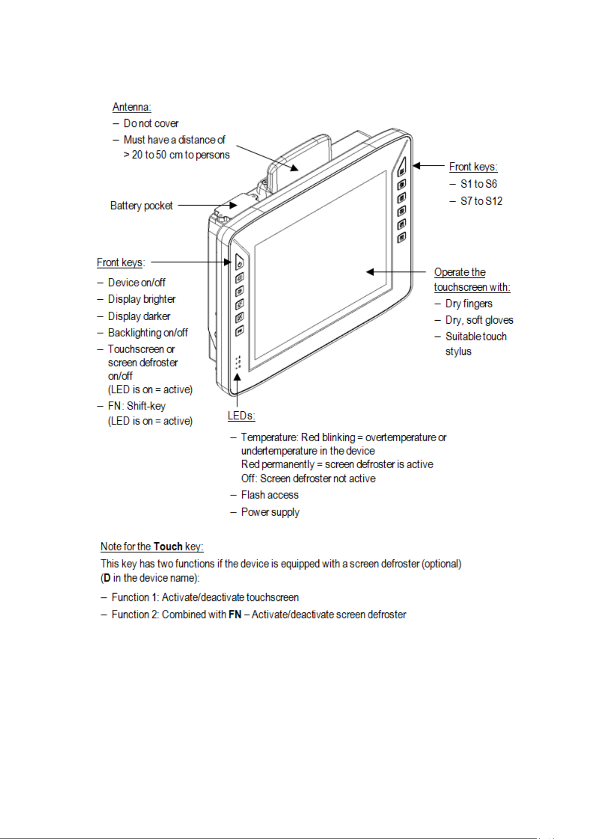
Operation
8.4.3. Front side: DLT-V7210 P, R, D and DLT-V7212 P, R, D
36 / 121 DLT-V72 Operating Instructions V2.50
Page 47

Operation
8.4.4. Front side: DLT-V7212 P+
DLT-V72 Operating Instructions V2.50 37 / 121
Page 48
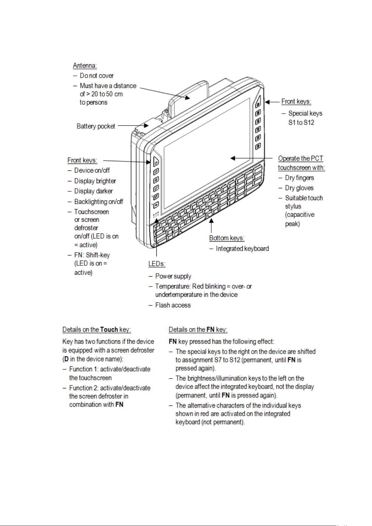
Operation
8.4.5. Front side: DLT-V7210 K, KD
38 / 121 DLT-V72 Operating Instructions V2.50
Page 49

Operation
8.4.6. Integrated keyboard
8.4.6.1. Language variants
The integrated keyboard of the DLT-V7210 K is available in three languages:
− English
− German
− French
The integrated keyboard of the DLT-V7210 KD is available in English.
Example English version (QWERTY)
Fig. 8.1: Integrated keyboard English (QWERTY)
8.4.6.2. Description of specific keys
Key Function
<Shift> key
Caps Lock: permanent switch to uppercase letters
FN key pressed has the following effect: The alternative characters of the individual
keys shown in red are activated on the integrated keyboard (not permanent).
Windows key
8.4.6.3. Integrated keyboard German (QWERTZ) features
Abb. 8.2: Integrated keyboard German (QWERTZ)
DLT-V72 Operating Instructions V2.50 39 / 121
Page 50
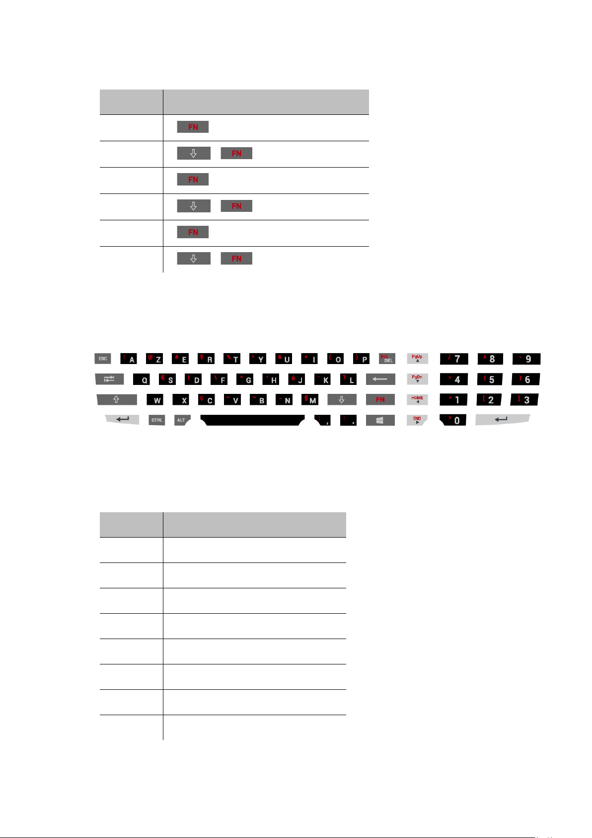
Operation
German „Umlaute“
Umlaut Press the keys successively:
ä
Ä
ö
Ö
ü
Ü
+ V + A
+ + V + A
+ V + O
+ + V + O
+ V + U
+ + V + U
8.4.6.4. Integrated keyboard French (AZERTY) features
Abb. 8.3: Integrated keyboard French (AZERTY)
Special characters French
Character Press the keys successively:
Æ ALT + 146
æ ALT + 145
Ç ALT + 128
É ALT + 144
ΠALT + 0140
œ ALT + 0156
» ALT + 175
« ALT + 174
40 / 121 DLT-V72 Operating Instructions V2.50
Page 51

Operation
8.5. Operating states
Status of LEDs
Supply voltage
OFF OFF Initial state, idle time – waiting for a new ignition
OFF FLASHING Temperature sensor faulty
FLASHING OFF DLT-V72 is in standby mode (S3)
OFF ON
ON OFF Computer start-up/normal operational
ON ON Screen defroster active
ON FLASHING Ambient temperature lies outside of the permitted
Temperature
DLT-V72 status
signal or for the <Power> key after switch-off; no
voltage supply
Computer will only start if the temperature in the
device is in the range between -30 and +59 °C
again.
state/shutdown delay time
range, i.e. < -30 or > +50 °C
DLT-V72 Operating Instructions V2.50 41 / 121
Page 52
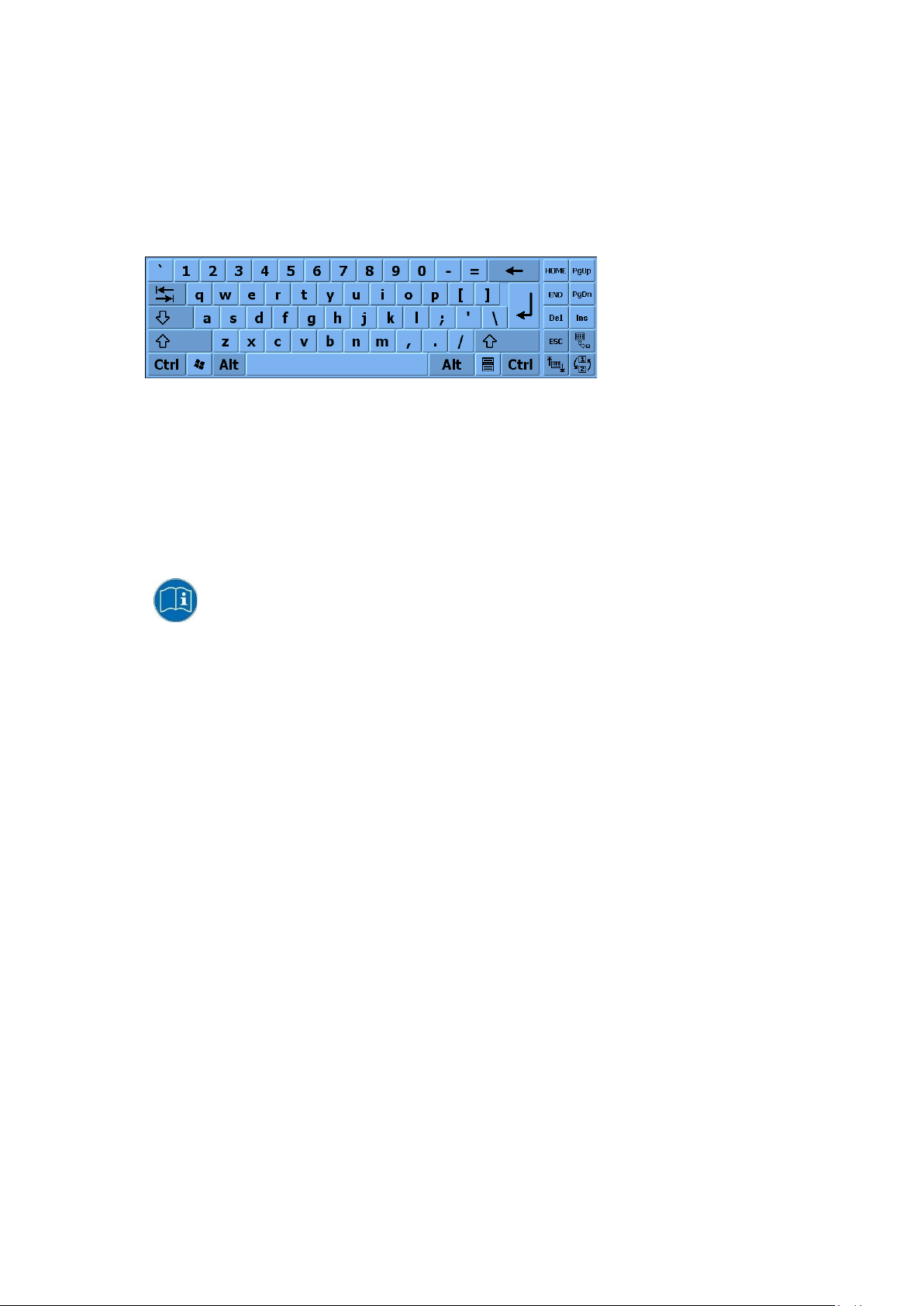
Operation
8.6. Software keyboard (optional)
The optional “DLoG software keyboard” brings the complete standard keyboard with function keys and numeric
pad directly to your DLT-V72 screen – with easy touch operation.
Any entries made, for example, letters and numbers, are passed to the currently active application program.
Example for a software keyboard (the layout can be configured individually):
Fig. 8.4: Software keyboard
If the software keyboard was ordered together wi th the DLT-V72 industrial PC, then the program will have been
fully pre-licensed by the Advantech production department. For subsequent installation, an installation program
is available.
The “DLoG software keyboard manual” is available on our websites.
42 / 121 DLT-V72 Operating Instructions V2.50
Page 53

Operation
WARNING
8.7. Operating the DLT-V72 with UPS
Personal injury due to short-circuit, fire, chemical burns, toxic substances.
DLT-V72 devices with integrated UPS contain lithium-ion battery packs. These can ignite if handled or
stored improperly (risk of fire), cause chemical burns or release toxic substances.
Use care when handling lithium-ion battery packs.
Do not damage lithium-ion battery packs; do not drill through and do not crush or drop.
Do not allow water or other liquids to come into contact with the device (exercise particular
caution with corrosive liquids).
Do not allow it to come into contact with fire.
For details about the UPS, see section 15.1 Integrated UPS (optional).
DLT-V72 Operating Instructions V2.50 43 / 121
Page 54

General device configuration
9. General device configuration
9.1. Operating systems (optional)
Please find the latest overview of all supported operating systems in the DLT-V72 data
sheets on our websites.
The following operating systems are available at the time of manual creation, June 2019:
− Windows 10 IoT Enterprise
− Windows 7 Pro
− Windows Embedded Standard 7
− Debian-based Linux
− IGEL Linux
9.2. MS-Windows (optional)
9.2.1. General
If a DLT-V72 with preinstalled operating system is placed into operation, this operating system will be loaded
after the BIOS system messages. System-specific device drivers (e.g. for graphics, sound, network,
touchscreen) are already installed.
In DLT-V72 units with a pre-installed operating system, the system is located on the C partition.
When a DLT-V72 is started up for the first time without a pre-installed operating system, the user needs to carry
out a number of steps that will vary depending on the system to be installed. Refer to the relevant operating
system manual for specific instructi ons .
9.2.2. Configuring the front keys, automatic shutdown, etc.
The “DLoG Config” software is used to configure DLT-V72 devices with a Microsoft Windows operating system.
For configuring DLT-V72, the “DLoG Config” version 5.0 or higher is required.
Configuration examples:
− Automatic shut down
− Front-key assignment
− Network settings
And depending on the equipment of the DLT-V72 also:
44 / 121 DLT-V72 Operating Instructions V2.50
− Battery pack charge settings (only on devices with optional UPS)
− Screen defroster heating function (only on devices with optional screen defroster)
− Operation with gloves possible (only on devices with optional PCT touchscreen)
The “DLoG Config manual” is available on our websites.
Page 55

General device configuration
NOTICE: Property damage
integrated UPS to stop functioning and need to be sent in for repair.
9.2.3. Energy options and battery pack durability
Valid for all MS Windows operating systems:
All DLT-V72 devices with MS Windows have had the power options set at the factory so that the
optimal duration of the battery pack can be achieved: The power saving plan is set to power options
(DLoG).
Do not modify or deactivate the power options (DLoG).
Under certain circumstances and configurations a modification may cause the battery pack of the
9.2.4. Suppress automatic Windows 10 updates
Under Windows 10, the automatic Windows updates can no longer be deactivated; the "Never check for
updates" setting in the Windows Update dialog is not available.
With the following entry in the Windows registry, the "Never check for updates" setting can be set anyw ay :
Manually create the following entry in the Windows registry (type "dwords"):
[HKEY_LOCAL_MACHINE\SOFTWARE\Policies\Microsoft\Windows\WindowsUpdate\AU]
"NoAutoUpdate"=dword:00000001
[HKEY_LOCAL_MACHINE\SOFTWARE\WOW6432Node\Policies\Microsoft\Windows\WindowsUpdate\AU]
"NoAutoUpdate"=dword:00000001
Restart Windows.
Via Start -> Settings -> Update & Security, switch to the Windows Updates dialog.
Click on Retry to search for updates.
Click on Advanced Options.
The Never check for updates setting is now set.
Fig. 9.1: Automatic Windows 10 Updates
To deactivate Never check for Updates:
Delete the entry manually from the Windows registry.
Restart the computer.
Search for updates.
DLT-V72 Operating Instructions V2.50 45 / 121
Page 56

General device configuration
9.3. Linux (optional)
The configuration of the DLT-V72 with Linux with regard to radio networks, touchscreen
calibration, etc. is described in the “Advantech Linux Manual”. Plea se cont act our
Technical Customer Support if required.
9.4. USB Recovery Stick
The optional recovery stick allows images to be backed up and restored onto the DLT-V72 w hen necessary
(backup & recovery).
The “USB Recovery Stick for ADLoG Terminals” user manual is available on our
websites.
9.5. Automatic shut down
Functional description
The DLT-V72 is equipped with an automatic shutdown module.
If wired up accordingly, the DLT-V72 conveniently switches off together with the vehicle’s ignition.
As disconnecting the power supply during operation can lead to data loss, the operating system needs to be
shut down normally using the appropriate hardware and software installed on the system when the ignition is
switched off.
The DLT-V72 is connected to the vehicle with three supply cables.
DC+ and DC- are directly connected to the power supply of the vehicle, the connection is of course run through
fuses. The supply voltage connected is then linked to the DLT-V72’s ignition input via a switch, for example, the
key switch of the ignition (also with a fuse).
Sequence
When the vehicle ignition is turned on or the DLT-V72 <Power> button is pressed, the DLT-V72 checks its
internal temperature and runs a test to confirm that the automatic shutdown function is working.
If this check of the environmental conditions is successful, the DLT-V72 starts the operating system normally.
Once these checks have been successfully completed, the DLT-V72 starts the operating system. No
environmental conditions (e.g. the internal temperature of the device or the state of the ignition input) are
checked for one minute during startup.
After one minute, the DLT-V72’s internal temperature and the state of the ignition input are constantly
monitored.
If the DLT-V72’s internal temperature reaches a critical level, a controlled shutdown of the operating system is
carried out. The computer will remain switched off until the temperature is once again within the permitted
range.
If the ignition input is grounded or isolated during normal operation of the DLT-V72, the device will switch to a
delayed shut-off state.
The device will continue to operate normally in this state until the shut-off delay (e.g. 20 minutes) has elap sed.
If the ignition is turned on again during this shut-off delay, the DLT-V72 will revert to a normal operational state.
Once the shut-off delay (after run time) has elapsed, the operating system will shut down and the device will
automatically shut down (e.g. after one minute or a signal from the operating system).
46 / 121 DLT-V72 Operating Instructions V2.50
Page 57

General device configuration
DLT-V72 with MS-Windows OS
„DLoG Config Manual“. Available on our Websites
Device shut down
If the operating system is shut down, all applications will be notified via the Windows message
“WM_QUERYENDSESSION” first.
Every application must then respond within the time set in the registry. If there is no response within the preset
time, the application will be hard-terminated.
It may not be possible to close an application automatically if it has unsaved data. Example: For example, the
WORDPAD.EXE program (included in Windows) cannot be closed automatically if there are unsaved changes.
In such a situation, WORDPAD.EXE will acknowledge the “WM_QUERYENDSESSION” Windows message by
prompting the user to choose whether to save or not.
All applications that can be terminated without user confirmation using the keyboard shortcut <ALT> + <F4> will
normally also respond correctly to the “WM_QUERYENDSESSION” message and therefore do not need to be
hard-terminated.
To ensure that important data is saved correctly, the application must respond appropriately to
“WM_QUERYENDSESSION”, i.e. the backup data must be saved without user confirmation and within the
preset time.
Automatic shutdown configuration
OS Configuration description
DLT-V72 with Linux OS „Advantech Linux Manual“. Please contact our Technical
Customer Support if required
DLT-V72 Operating Instructions V2.50 47 / 121
Page 58

WLAN configuration
10. WLAN configuration
10.1. Safety notes
CAUTION
Danger of radiation emission.
DLT-V72 devices with radio technology emit high frequency energy (abbreviation: HF).
To protect persons and domestic animals against HF radiation:
Mount the DLT-V72 so that persons and domestic animals maintain a minimum distance
of 20 to 50 cm from the radio antennas.
Ensure that persons observe this minimum distance when operating the DLT-V72.
High frequency energy can interfere with technical devices. For this reason, do not use the DLT-V72 in the
vicinity of pacemakers or other medical devices.
Only operate the DLT-V72 with radio modules that are approved by the manufacturer for this device.
Make sure that the transmission power and the radio frequency of the DLT-V72 comply with the regulations
for the respective country where the device is deployed.
Observe all applicable regulations for your deployment location/country with regard to operating channels,
radio frequencies and the maximum permissible transmitting power. Responsibility for this lies with the
company operating the DLT-V72. The regulatory authorities in the relevant country can provide information
on this.
Any modifications to the DLT-V72 which are not expressly approved by the party responsible for the compliance
can lead to the withdrawal of the operating license for this device.
Examples of country-specific regulations:
Region: Radio approval:
EU RED (formerly R&TTE)
China SRRC
Japan MIC (formerly TELEC)
Taiwan NCC
Canada Canada IC
USA FCC
Antenna solutions for use in Germany
The Advantech antenna solutions are based on the prevailing IEEE 80 2.11 sta ndard. This standard allows radio
data transfer at rates from 1 Mbps to 54 Mbps (867 Mbit/s if using IEEE 802.11ac) using the 2.4 GHz and
5 GHz frequency band.
48 / 121 DLT-V72 Operating Instructions V2.50
Page 59

WLAN configuration
Information on radio performance
The consistency of the radio performance is dependent on the following factors:
− Radio card (set transmission power)
− Connecting cables
− Antenna gain
Help table for the correct setting:
10.2. Configuration differences between MS Windows and Linux
The radio configuration of the DLT-V72 with MS Windows operating system is descri bed in t he follow ing man ual
sections. The radio configuration of the DLT-V72 with Linux is described in the “Advantech Linux Manual”.
Please contact our Technical Customer Support if required.
10.3. Preparation work at the factory
The following preparations have already been carried out at the factory for the optional radio functionality of the
DLT-V72:
− The radio card and the corresponding drivers are installed.
− A default profile with basic settings is defined.
NOTICE: Property damage
No access to radio cards in the DLT-V72
Radio cards are located inside the devices and are not accessible from the outside.
Only the manufacturer and its authorized service centers may open the device and install/remove radio cards.
DLT-V72 Operating Instructions V2.50 49 / 121
Page 60
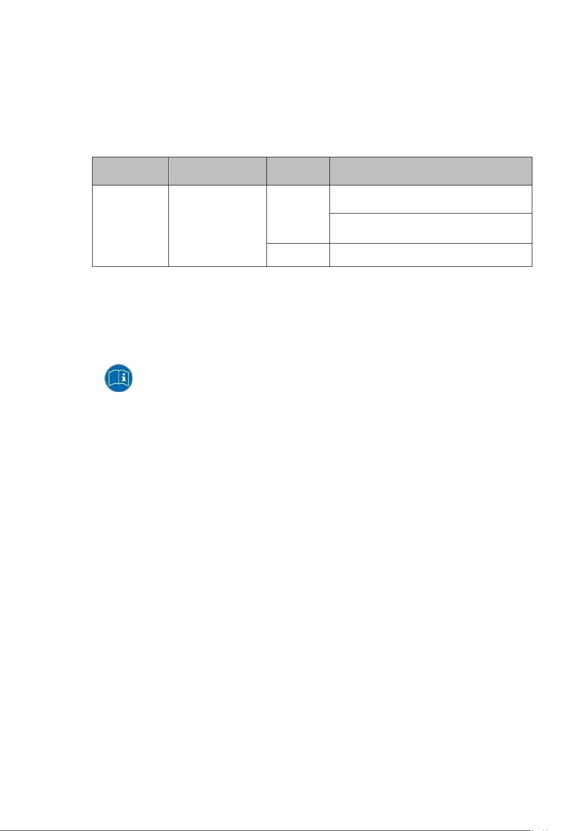
WLAN configuration
Operating
system
10.4. Customer-specific settings
To create a customer-spe cif ic profil e:
Use the configuration program that is already factory-installed on the DLT-V72.
Observe the description of the configuration programs in the following sections.
Radio card
SPARKLAN
WPEQ 261
ACN (BT)
Qualcomm Atheros
QCA61x4A Wireless
Network Adapter
Windows
Linux Linux Configuration Utility
10.5. Windows Zero Configuration (WZC)
Configuration program
Advantech WLAN Client Manager (IGX Tool)
Password: gold
Wireless Zero Configuration (abbreviation: WZC)
No password required
WZC (Windows Zero Configuration) is a tool for automatic WLAN configuration in MS Windows.
Comprehensive information can be found in the online help for the progr am.
50 / 121 DLT-V72 Operating Instructions V2.50
Page 61

WLAN configuration
The following steps should be performed as the Administrator for the installation process.
10.6. Advantech WLAN Client Manager (IGX Tool)
10.6.1. Area of application
This chapter describes the Advantech WLAN Client Manager program version 1.00 under the following
operating systems:
− Win7Pro
− WinEmbStd7
− Win8.1IndPro
− Win10IoTEnt
This chapter applies to DLT-V72 devices with the Radio card "SPARKLAN WPEQ-261ACN(BT) MiniPCIe".
10.6.2. After image reinstallation: Driver installation
If the image has been reinstalled, the DLT-V72 must be set up again using the IGX WLAN driver.
Two drivers are available:
− Driver for Win7Pro \ WinEmbStd7
− Driver for Win8.1IndPro \ Win10IoTEnt
10.6.3. Requirements
The currently available IGX drivers can be downloaded from the following website:
www.advantech-service-iot.eu -> Downloads -> Service -> Drivers -> Link to FTP:
Advantech-DLoG_Products\Additional-DriversSoftware\WLAN_driver\X86_(DLoG_MPC_MTC_IPC_series\Sparklan_261_ACN_BT
Once the download has completed, the content s of the ".zip" directory on the desktop must be unzipped.
NOTES
The IGX driver needs a valid licence.
DLT-V72 Operating Instructions V2.50 51 / 121
Page 62

WLAN configuration
Setup.exe in the main folder is not supported in WinEmbStd7.
10.6.4. Driver installation WinEmbStd7
If it is not known which operating system variant (32 or 64 bit) is installed on the DLT-V72, the system overview
can be used for testing:
Fig. 10.1: System overview in Control Panel
For 32 bit systems:
Open the subfolder Win7_X86.
Run Setup.exe to start the installation.
For 64 bit systems:
Open the subfolder Win7_X64.
Run Setup.exe to start the installation.
NOTE
52 / 121 DLT-V72 Operating Instructions V2.50
Page 63

WLAN configuration
The remaining installation workflow is covered in the next chapter and is identical in all operating systems.
Example screenshot for 64 bit system, subfolder Win7_X64:
Fig.10.2: Setup.exe for 64 bit operating system in the subfolder Win7_X64
NOTE
DLT-V72 Operating Instructions V2.50 53 / 121
Page 64
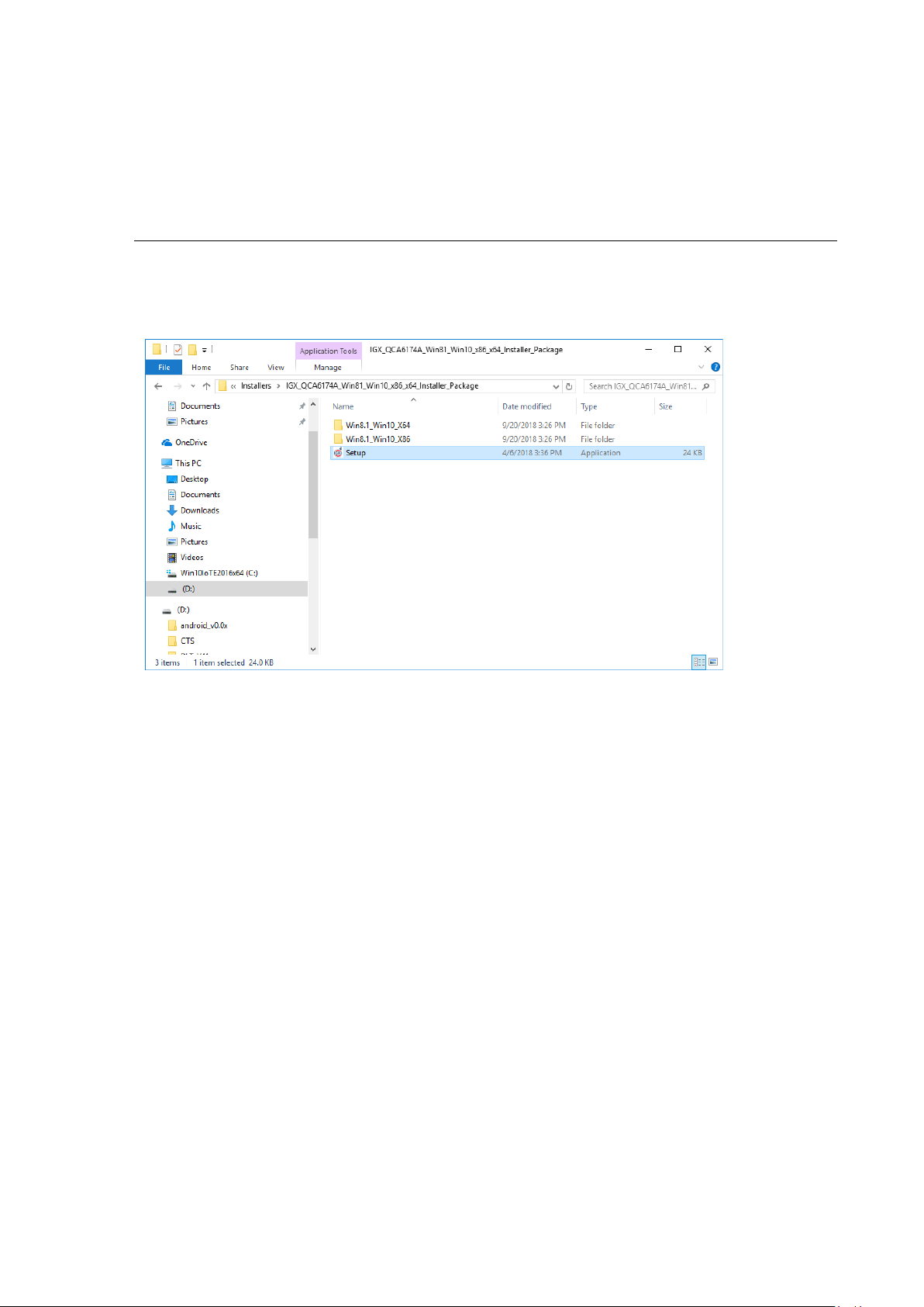
WLAN configuration
For Windows7 installation, please use the corr e sp ondi ng Win7 driver .
10.6.5. Driver installation Win7Pro / Win 8.1 IndPro / Win 10 IoT
Open the corresponding installation directory depending on the operating system.
Run Setup.exe to start the installation.
NOTE
The following installation example shows the Win8.1 / 10 driver.
Fig.10.3: Setup.exe for 64 bit operating systems Win8.1 / 10
If the C++ executables / runtimes required for the installation are missing on the operating system, these must
be set up before running the WLAN driver installation.
Respond to the relevant prompt in the installation workflow.
54 / 121 DLT-V72 Operating Instructions V2.50
Page 65

WLAN configuration
On completion, the following window is displayed that starts the actual driver installation process:
Fig.10.4: IGX driver installation Welcome dialog
Continue the installation with Next:
Fig.10.5: IGX driver installation user and company name
In this dialog, enter a username and a company name and confirm with Next.
DLT-V72 Operating Instructions V2.50 55 / 121
Page 66

WLAN configuration
Fig.10.6: IGX driver installation All program features
Leave the Complete option enabled.
Continue the installation with Next.
56 / 121 DLT-V72 Operating Instructions V2.50
Fig.10.7: IGX driver installation starts
Continue the installation of the required files with Install.
Page 67
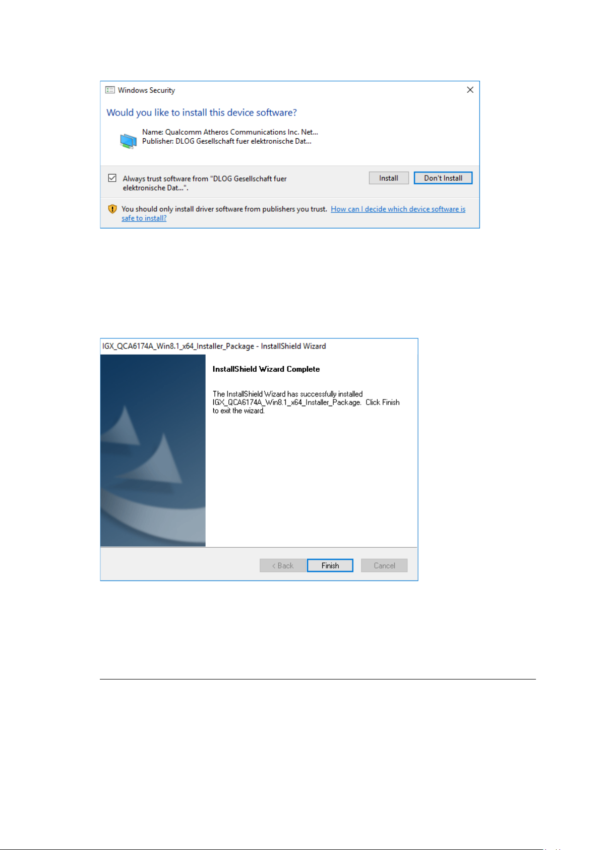
WLAN configuration
It is recommended to run the required system re-start directly following installation.
During installation, the following window is opened:
Fig.10.8: IGX driver installation Windows Security
Ensure that the Always trust software from… option has been selected.
Continue the driver installation with Install.
Fig.10.9: IGX driver installation Exit with Finish
Exit the driver installation with Finish.
NOTE
Select Yes, I want to restart my computer now.
Press the Finish button.
DLT-V72 Operating Instructions V2.50 57 / 121
Page 68

WLAN configuration
The system re-start is carried out.
Fig.10.10: IGX driver installation Perform computer re-start
58 / 121 DLT-V72 Operating Instructions V2.50
Page 69

WLAN configuration
10.6.6. Start WLAN Client Manager, Login
Launch the WLAN Client Manager by double-clicking the Launch WCU icon:
Fig.10.11: WCU icon on the desktop
You must login as "WCU_Administrator" first.
To do this, click Admin Login.
Fig.10.12: WCU main window, Admin Login
DLT-V72 Operating Instructions V2.50 59 / 121
Page 70
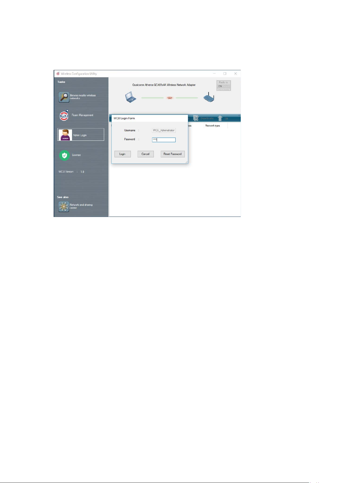
WLAN configuration
Then open the login window.
Enter the passport, which by default is "gold".
Confirm the input with the Login button.
Fig.10.13: WCU-Administ rat or l ogin window
60 / 121 DLT-V72 Operating Instructions V2.50
Page 71

WLAN configuration
terminal.
10.6.7. WLAN Client Manager functions
10.6.7.1. License
The License function lists the curren t statu s of the enabled o pt ion s:
Fig.10.14: Check License
NOTE
The correct implementation of the WLAN driver requires a valid license in combination with the DLT-V72
If, as shown in the image, the license information is missing:
Contact technical customer support to solve the problem.
Fig.10.15: Info display via existing license
DLT-V72 Operating Instructions V2.50 61 / 121
Page 72

WLAN configuration
10.6.8. Browse nearby wireless networks
10.6.8.1. Set up the WLAN connection
To set up a WLAN connection, you can show all available networks using the Browse nearby wireless
networks function.
You can select the appropriate network from here.
Fig.10.16: Browse nearby wireless networks function
62 / 121 DLT-V72 Operating Instructions V2.50
Page 73
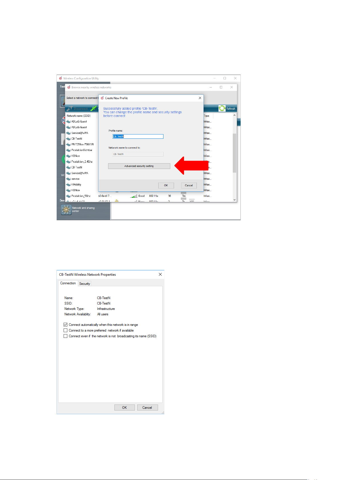
WLAN configuration
10.6.8.2. Define security settings
The security settings must now be selected depending on the network.
These settings can be made in the Advanced Security Setti ngs section:
Fig.10.17: Advanced Security Settings dialog
To be able to connect with the network automatically, set the checkmark to connect automatically when the
network is in range:
Fig.10.18: Connection when the network is in range dialog
DLT-V72 Operating Instructions V2.50 63 / 121
Page 74

WLAN configuration
Available parameters in the Connection and Security sections:
Connection
Connect automatically when the
network is in range
Enable this parameter to set up an automatic connection
to the network.
Connect to a more preferred network
if available
Connect even if the network is not
broadcasting its name (ssid)
The security settings (Fig.10.17: Advanced Security Settings dialog ) must be adapted. These settings differ
depending on the network.
The Security Type must be selected first. The following options are available:
− No authentication (Open)
− WPA2-Personal
− WPA2-Enterprise
− CCKM
The encryption process (Encryption Type) is then selected. The options available here depend on the selected
Se cu rity Type.
− None
− WEP
− AES
In the event of multiple profiles being present, this option
can be used to select the preferred profile.
This option can be used to set that a connection is still
established when the name of the network is not being
transmitted.
64 / 121 DLT-V72 Operating Instructions V2.50
Page 75

WLAN configuration
This results in the following selection optio ns and sett ing s:
Fig.10.19: Sec urity settings - network authentication methods
The network authentication methods shown, as well as their designations, differ depending on the operating
system used.
DLT-V72 Operating Instructions V2.50 65 / 121
Page 76
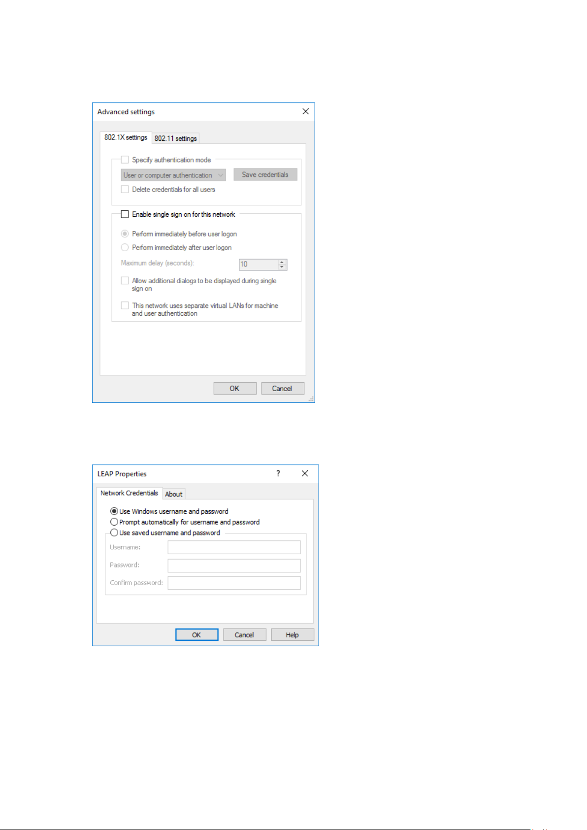
WLAN configuration
For the remaining settings as in the case shown above (Cisco: Leap), the required additional parameters are
carried out using the two buttons Settings and Advanced settings.
Fig.10.20: Sec urity settings – Advanced settings (Cisco: Leap)
Fig.10.21: Sec urity settings – LEAP properties
66 / 121 DLT-V72 Operating Instructions V2.50
Page 77

WLAN configuration
Lastly, the network key must be entered in the following example (WPA2-Personal) (Network Security
Key).
Confirm the settings with OK.
Fig.10.22: Wireless Network properties dialog
DLT-V72 Operating Instructions V2.50 67 / 121
Page 78

WLAN configuration
Fig.10.23: Create new profile dialog
Confirm the new profile with the OK button.
68 / 121 DLT-V72 Operating Instructions V2.50
Page 79

WLAN configuration
10.6.8.3. Establish network connection
After the WLAN profile settings have been made, a connection to the network is established automatically.
The connection setup with the selected network is successful only if the "green" connection line is display ed in
the WCU main window.
Fig.10.24: Network connection is established
DLT-V72 Operating Instructions V2.50 69 / 121
Page 80

WLAN configuration
10.6.9. Roam Management
10.6.9.1. General
After clicking the General dialog, the following information is displayed on the screen:
Fig.10.25: General dialog in the Roam Management menu
General
Info Meaning of the display
Client Status Current connection status: Connected / Disconnected
Network Name SSID SSID of the currently connected access points
Network Type Network type Ad-hoc or Infrastructure
AP BSSID Correspondi ng M AC address of the curr ently conn ect ed acc ess points
Channel Displays the configured channel used in the access point
Mode Frequency band used, e.g. "802.11g"
Signal Strength (dBm) Current signal strength of the connected access points in (dBm)
SNR Relative signal strength (SNR) as bar chart
Radio Power on Time (sec) Display of the current elapsed operating time of the Radio card
Country Code The country code supplied by the access point such as US, DE, JP
IP Address The Client IP address configured by the access point (DHCP) or manually
(static ) assigned
CCX AP Name SSID of the Cisco CCX Access Points (if present)
70 / 121 DLT-V72 Operating Instructions V2.50
Security
Authentication The authentication process used, e.g. WPA2-PSK (Pre-Shared-
Key)
Encryption Display of the corresponding encryption process, e.g. (AES-CCMP,
TKIP)
Page 81
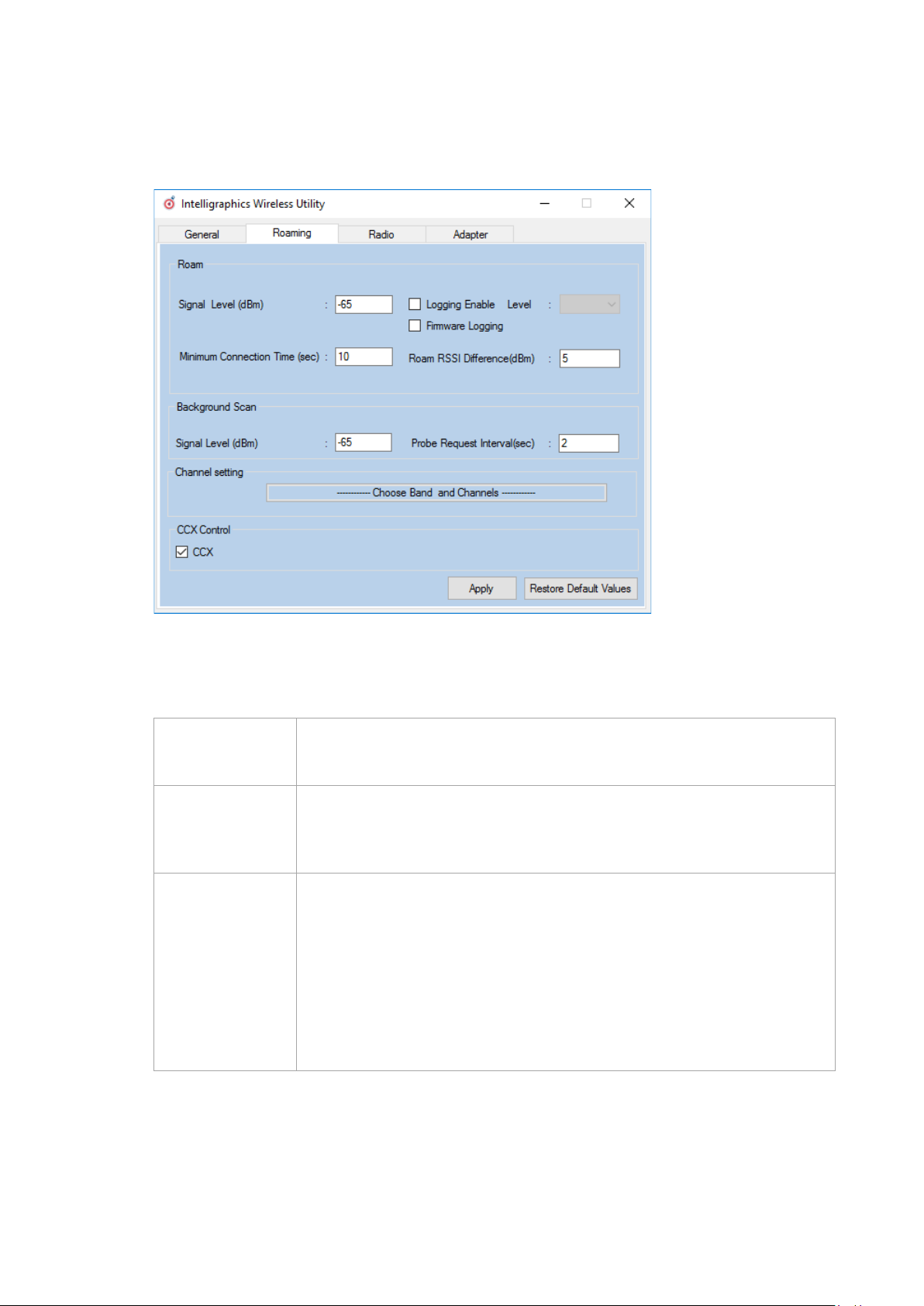
WLAN configuration
10.6.9.2. Roaming
The Roaming dialog is used to define the following parameters:
Fig.10.26: Roaming dialog in the Roam Management menu
Roam
Signal Level (dBm): This setting defines when the client is to be begin the roaming process.
Minimum
Connection Time
(sec)
Logging Enable
Level
Possible values: -55 dBm to -80 dBm
Default value: -65 dBm (adjustable in 5 dBm increments)
This setting defines how long the client is to remain connected to the current access
point before roaming to the new access point starts.
Possible values: 5 to 25 seconds
Default value: 10 seconds
This setting can be used to define that the activities of the driver are recorded in a
log. Two levels are available: Critical and All.
Critical: If the debug level is set to Critical, only the critical messages from the
driver will be recorded.
All: If the debug level is set to All, all messages from the driver will be recorded.
The log file is saved in the C:\WlanLogs folder and a current timestamp is added.
If the log file is larger than 100 mb, a new file is created.
NOTE: This option should only be enabled for short periods for analysis purposes,
not permanently!
DLT-V72 Operating Instructions V2.50 71 / 121
Page 82

WLAN configuration
Firmware Logging Option can be enabled to create a "Firmw are" log .
The log file is saved to the C:\WlanLogs folder and is assigned the current
timestamp and the extension _fw.
If the log file is larger than 100 mb, a new file is created.
NOTE: This option should only be enabled for short periods for analysis purposes,
not permanently!
Roam RSSI
Difference (dBm)
The client will not connect to the new access point until the defined RSSI difference
between the new visible access point and the currently connected access point is
reached.
Possible values: 5 dBm to 25 dBm
Default value: 5 dBm
Background Scan
Signal Level (dBm) This setting defines when the client is to begin the background scan.
Possible values: -55 dBm to -80 dBm
Default value: -65 dBm
Probe request
interval
This setting is used to define how frequently the probes are to be sent when the
client is in the "Connected" status.
The minimum value here is 1 second.
The maximum value is 10 seconds.
Each scan process (repetition) takes 4 to 5 seconds.
Clicking the Choose Band and Channels button opens the follow ing dia log:
72 / 121 DLT-V72 Operating Instructions V2.50
Fig.10.27: Roam Management – Choose Band and Channels
Page 83

WLAN configuration
Channel List
Select all 2.4Ghz
channels
This option can be used for simultaneous pre-selection of all 2.4 GHZ channels
1 to 13 supported by the WLAN driver.
Modifications to individual channels can be carried out at any time by clicking
the checkboxes for each channel.
NOTICE: Country-specific channel settings / residual restrictions on the use of
special channels should be set according to the legal guidelines and must be
observed!
Select all 5Ghz
channels
This option can be used for simultaneous pre-selection of all 5 GHZ channels
36 to 140 supported by the WLAN driver.
Modifications to individual channels can be carried out at any time by clicking
the checkboxes for each channel.
NOTICE: Country-specific channel settings / residual restrictions on the use of
special channels should be set according to the legal guidelines and must be
observed!
Select all channels Used to select or de-select the complete channel list 2.4/5 GHZ (to simplify
channel selection).
Band The following selection options are available:
− 2.4 GHz
− 5 GHz
− Dual band (2.4 GHz and 5 GHz)
The corresponding settings mean that only channels occurring in the frequency
band are displayed for selection and de-selection.
CCX Control
CCX / CCKM The CCX specification (Cisco
®
Compatible eXtensions) contains a series of
functional extensions to the IEEE 802.11 WLAN standard to support rapid
roaming (CCKM): with improved security, reliability and diagnostic
performance.
®
The CCX specification is a brand from Cisco
and requires a license
agreement to be able to equip mobile devices with this technology.
Currently the CCX versions 4 (CCXv4) and 5 (CCXv5) are supported.
DLT-V72 Operating Instructions V2.50 73 / 121
Page 84

WLAN configuration
10.6.9.3. Radio Tab
The Radio dialog is used to define the following parameters:
Fig.10.28: Radio dialog in the Roam Management menu
Power Save The Power Save Level is set.
Mode Selection The band of the client is specified.
The levels OFF and Auto-PSM are available.
The possible options are: 11n and 11ac / 11n / 11a/b/g
74 / 121 DLT-V72 Operating Instructions V2.50
Page 85

WLAN configuration
10.6.9.4. Adapter Tab
After clicking the Adapter dialog, the following information is displayed on the screen:
Fig.10.29: Adapter Tab in Roam Management menu
DLT-V72 Operating Instructions V2.50 75 / 121
Page 86

WWAN configuration
11. WWAN configuration
11.1. Safety notes
CAUTION
Danger of radiation emission.
DLT-V72 devices with radio technology emit high frequency energy (abbreviation: HF).
To protect persons and domestic animals against HF radiation:
Mount the DLT-V72 so that persons and domestic animals maintain a minimum distance
of 20 to 50 cm from the radio antennas.
Ensure that persons observe this minimum distance when operating the DLT-V72.
High frequency energy can interfere with technical devices. For this reason, do not use the DLT-V72 in the
vicinity of pacemakers or other medical devices.
Only operate the DLT-V72 with radio modules that are approved by the manufacturer for this device.
Make sure that the transmission power and the radio frequency of the DLT-V72 comply with the regulations
for the respective country where the device is deployed.
Observe all applicable regulations for your deployment location/country with regard to operating channels,
radio frequencies and the maximum permissible transmitting power. Responsibility for this lies with the
company operating the DLT-V72. The regulatory authorities in the relevant country can provide information
on this.
Any modifications to the DLT-V72 which are not expressly approved by the party responsible for the compliance
can lead to the withdrawal of the operating license for this device.
Examples of country-specific regulations:
Region: Radio approval:
EU RED (formerly R&TTE)
China SRRC
Japan MIC (formerly TELEC)
Taiwan NCC
Canada Canada IC
USA FCC
76 / 121 DLT-V72 Operating Instructions V2.50
Page 87

WWAN configuration
11.2. Preparation work at the factory (DLT-V72 delivery status)
The following preparations have already been carried out at the factory for the optional WWAN functionality of
the DLT-V72:
− The WWAN card and the corresponding drivers are installed.
− GNSS is enabled at the factory
NOTICE: Property damage
No access to radio cards in the DLT-V72
Radio cards are located inside the devices and are not accessible from the outside. Only the manufacturer and
its authorized service centers may open the device and install/remove radio cards.
11.3. SIM card for WWAN (customer-specific)
A SIM card is required in addition to the WWAN card.
The SIM card must be plugged in into the SIM card slot underneath the DLT-V72 antenna:
Fig. 11.1: Sim card slot underneath the DLT-V72 antenna
NOTICE: Property damage
Inserting the SIM card: DLT-V72 must be switched off.
TIP
If the SIM card contains a PIN, the customer must set up an application for the PIN query.
For this reason, we recommend not using a PIN.
DLT-V72 Operating Instructions V2.50 77 / 121
Page 88

WWAN configuration
11.4. Configuration of Radio card QUECTEL EC25
The following information is valid for the Radio card QUECTEL EC25. Its precise designation is:
− USA: QUECTEL EC25A or EC25V
− Europe: QUECTEL EC25E
The WWAN configuration is identical for both Radio cards. For this reason, the abbreviation QUECTEL EC25 is
used.
11.4.1. Establish Internet connection
NOTE
In the section below, the provider Vodafone is used as an example. Adjust the settings for your provider.
Open the Network and Sharing
Center.
Click Set up a new connection or
network.
Fig. 11.2: QUECTEL EC25 - Set up a new connection or network
Fig. 11.3: QUECTEL EC25 - Connect to the Internet
Connect to the Internet - select
and confirm.
78 / 121 DLT-V72 Operating Instructions V2.50
Page 89
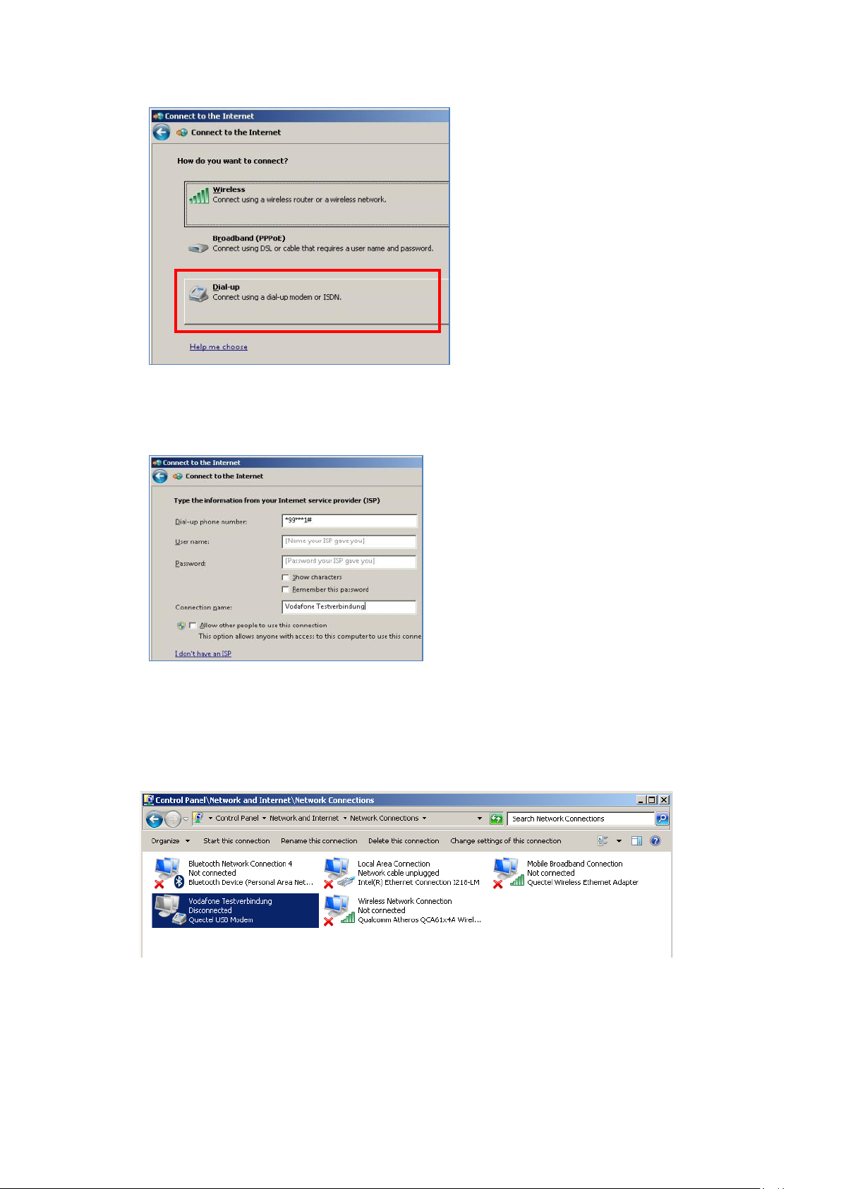
WWAN configuration
Click Dial-up.
Fig. 11.4: QUECTEL EC25 - Connect to the Internet - Dial-up
Specify as a telephone number, e.g.
*99***1#.
Enter a connection name, e.g.
Vodafone test connection.
Username and password are not
required in the example. (Providerdependent)
Fig. 11.5: QUECTEL EC25 - Connect to the Internet - Telephone number
Open the Vodafone test connection under Network conne cti ons.
Fig. 11.6: QUECTEL EC25 - Network connections - Vodafone test connection
DLT-V72 Operating Instructions V2.50 79 / 121
Page 90

WWAN configuration
Do not enter a user name or password.
Click Dial.
The test connection is established.
Fig. 11.7: QUECTEL EC25 - Dial Vodafone test connection
In the Network and activation center of the device, the status of the test connection can be tested:
Right-click the network and then select Status.
80 / 121 DLT-V72 Operating Instructions V2.50
Fig. 11.8: QUECTEL EC25 - Function test GSM / GNSS, test connection status
Page 91
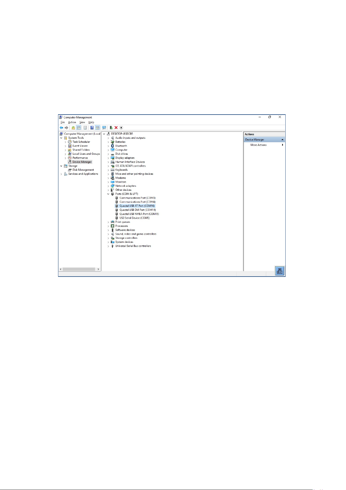
WWAN configuration
11.4.2. Trouble Shooting
11.4.2.1. Test virtual COM ports
In the device manager it is possible to test that the virtual COM ports are correctly set.
If they are not correctly set, they must be modified as appropriate.
The virtual COM ports must be set up as shown in the figure:
Fig. 11.9: QUECTEL EC25 - Virt ual COM ports DLT-V72
DLT-V72 Operating Instructions V2.50 81 / 121
Page 92
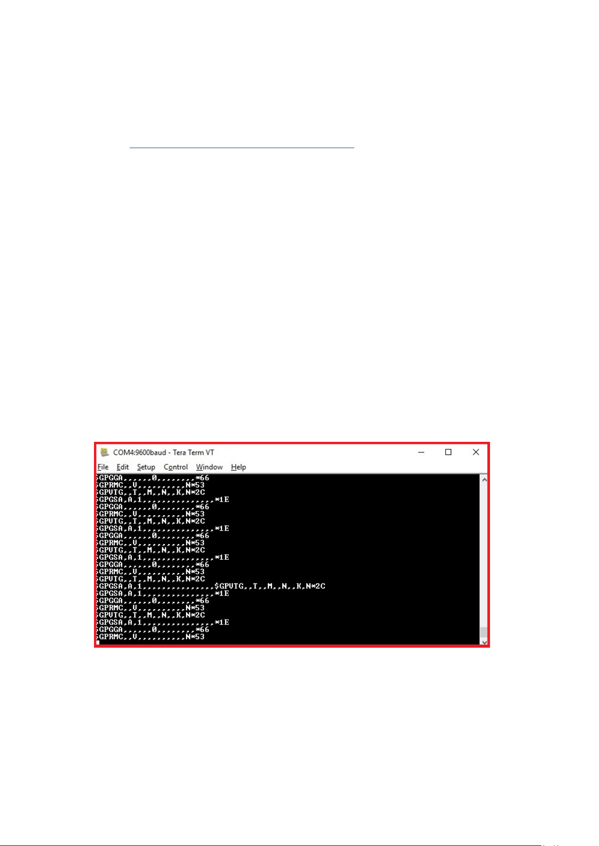
WWAN configuration
11.4.2.2. Test communication between DLT-V72 and WWAN Radio card
The open source software Tera Term, for example, can be used to test that the DLT-V72 can communicate
with the Radio card.
This software can be downloaded from the following URL, for example (webs ite available at time of writing this
operating manual, dated May 2019):
https://www.heise.de/download/product/tera-term-51776
Perform the following steps:
Open the AT port via Tera Term.
Connect to the AT port.
In the AT port, enter the command AT.
If the response received is OK, communication is present.
11.4.2.3. Test that GNSS data can be received
The open source software Tera Term, for example, can be used to test that GNSS data can be received.
Availability of the software: se e previou s sect ion .
Perform the following steps:
Open the NMEA port via Tera Term.
Test that NMEA data are received.
Enabled data flows are displayed.
Example:
Fig. 11.10: QUECTEL EC25 - Test NMEA data flows
82 / 121 DLT-V72 Operating Instructions V2.50
Page 93

Mechanical installation
WARNING
NOTICE: Property damage
12. Mechanical installation
12.1. Safety notes
Risk of injury and damage due to improper mechanical installation.
These mounting instruction are directed to skilled personnel. Only qualified skilled personnel may perform
the mechanical installation work on the DLT-V72. If the DLT-V72 is incorrectly mounted, any warranty for
this device will be void.
The mounting of the DLT-V72 must not endanger the safety of the operating personnel.
Example: When mounting to forklifts, the driver's field of view must remain free.
Hazardous voltage, electric shock fro m con tact with liv e parts.
Do not put the DLT-V72 into operation if it is visibly damaged.
Do not open or modify the DLT-V72.
Risk of injury due to weight and sharp-edged parts.
The DLT-V72 can fall down and cause injuries due to its weight.
The strain relief rail can have sharp edges and cause cutting injuries.
Always hold the DLT-V72 by the housing with both hands.
Never use the antenna as a handle. It can break due to the weight involved.
Do not hold the DLT-V72 by the strain relief rail.
Use the assistance of a second person for installation work.
Damage and scratching of the touchscreen without transport protective film.
The front display of the DLT-V72 is protected during transport by a transparent film. This film should remain
on the front display during assembly to avoid damage to the front display surface.
Only remove the film after all of the installation work has been completed.
DLT-V72 Operating Instructions V2.50 83 / 121
Page 94

Mechanical installation
12.2. Overview: Recommended mounting sequence
Requirement: The vehicle/installation location must be prepared (e.g. connection to the ignition, correct
voltage, etc.)
− Find a suitable installation position for the DLT-V72.
− Secure the device mounting (RAM or mounting bracket) to the targeted subject/vehicle.
− Connect external accessories to the DLT-V72.
− Install an easily accessible disconnecting device such as a switch close to the device.
− Connect all cables (power supply, peripherals).
− Close off all unused cable openings of the rubber seal using the accomp any ing bli nd plug s
so that they are sealed.
− Close the DLT-V72 with the cable cover.
− Install the DLT-V72 on the device mounting.
84 / 121 DLT-V72 Operating Instructions V2.50
Page 95

Mechanical installation
WARNING
NOTICE: Property damage
specific application area.
12.3. Mounting the DLT-V72 at the deployment location
Risk of injury and damage due to improper deployment location.
Observe the intended use of the DLT-V72, e.g. not in potentially explosive areas, not in life-supporting
facilities.
Ensure that the deployment location of the DLT-V72 complies with the permissible environmental
conditions.
The installation height of the device shall not exceed 2 m.
Risk of accident on vehicles due to unstable attachment of the DLT-V72.
When installing the DLT-V72, make sure that if the bracket breaks (e.g. because of a stress fracture)
no one will be injured.
Alternatively please put appropriate safety measures in place (e.g. install a security cable in addition to
the mounting bracket).
Radio wave emission in the vicinity of persons.
To ensure that the limits set for exposure to radio waves are not exceeded:
Install the DLT-V72 so that persons maintain a minimum distance of 20 to 50 cm to the antenna.
Installation environment without cooling air can over hea t / damage the DLT-V72.
The DLT-V72 employs a passive cooling concept whereby the waste heat ge ner at ed ins ide the devi ce is
emitted from the surface of the housing. For this system to function properly, sufficient fresh air circulation
is required. If there is no access to fresh cooling air, it may result in overheating and severe damage to the
device.
Never install the system in a closed environment where the cooling air is unable to dissipate accumulated
heat to the outside.
The maximum permissible ambient temperature for the entire system needs to be taken into account for the
DLT-V72 Operating Instructions V2.50 85 / 121
Page 96

Mechanical installation
DANGER
12.3.1. Electrically isolated DLT-V72 mounting
Risk of accident on vehicles due to unexpected vehicle emergency stop because of electroconductive connection of the DLT-V72 to the vehicle chassis.
Due to a variety of technical properties of forklifts and forklift trucks, it can be necessary to electrically
isolate DLT-V72 from the chassis of the vehicl e to prevent malf un cti ons .
The necessity of this must be studied on a case-by-case basis, however, it is recommended for vehicles
with potential-free chassis.
For example, using rubber buffers ensures that the terminal has no electrically conducting connection
to the vehicle chassis.
If peripheral equipment (such as scanners, printers, scales or similar), which has its own power supply
unit is used, you must ensure that the power supply units of these peripherals are galvanically
separated from the supply of the vehicle. Moreover, the peripheral equipment and its cabling must be
attached electrically isolated.
If external antennas are being used, you must ensure that the antennas are isolated at the mounting
point on the vehicle chassis.
86 / 121 DLT-V72 Operating Instructions V2.50
Page 97

Mechanical installation
WARNING
NOTICE: Property damage
misused.
12.4. Attaching accessories to the DLT-V72
Risk of accident during vehicle operation if the mounting of the DLT-V72 becomes loose and breaks
while driving.
Ensure the following when attaching the mounting on the VESA mounting hole pattern:
− Special mechanical knowledge is required for correct mounting!
− Use suitable mounting material.
− Use suitable screws: Screws that are too long can penetrate the back of the DLT-V72 and cause
irreparable damage. Screws that are too shor t do not prov ide secur e mount ing .
− Use suitable washers.
− Observe the maximum screw-in depth of the hole of the mounting hole pattern: The recommended
screw-in depth of Dx1 always applies (screw diameter x 1).
− If you ordered a bracket from Advantech, it includes the suitable screws and washers. Please use
them.
Only use mounting brackets, accessories and mounting materials that have been tested and approved for
the respective DLT-V72. Otherwise, any warranty for this device will be void.
All mounting brackets, accessories and mounting materials supplied by Advantech are only intended to be
used for attachment of the Advantech Industrial Computers and the peripheral devices and may not be
12.4.1. VESA mounting hole pattern
The rear side of the DLT-V72 has a VESA-compatible mounting hole pattern with 75 x 75 mm for a RAM Mount
bracket or swivel mounting.
Screw-in depth VESA mounting hole pattern: M6 x 6 mm
Suitable mounting material:
− Cylinder-head screws int.hex DIN912 M6
− Washers ISO 8738 (DIN 1440)-A6-A2
Fig. 12.1: VESA mounting hole pattern on the rear side of the DLT-V72
DLT-V72 Operating Instructions V2.50 87 / 121
Page 98

Mechanical installation
12.4.2. Attach the mounting bracket
The housing of the DLT-V72 has holes provided for attaching a mounting bracket.
Fig. 12.2: Mounting bracket on the DLT-V72
12.4.3. Attach accessories
The housing of the DLT-V72 has holes provided for attaching an accessory. Example:
Screw-in depth: M6 x 6 mm
Suitable mounting material:
− Cylinder head screws DIN912 M6
− Washers DIN 125 - A 6.4
Screw-in depth: M6 x 6 mm
Suitable mounting material:
− Cylinder head screw DIN 912 M6
− Washer ISO 8738 - A6-A2
88 / 121 DLT-V72 Operating Instructions V2.50
Fig. 12.3: Scanner mounting attachment
Installation sequence if mounting bracket and additional accessory are being attached
If you are mounting a mounting bracket and a keyboar d hold er:
− Attach the mounting bracket to the DLT-V72 first.
− Then mount the keyboard holder.
− Only mount the complete system at the deployment location, e.g. to the forklift.
Please note: In addition to the mounting bracket, one accessory holder per side can still be attached in each
case.
Page 99

Electrical installation, cables, cable cover
WARNING
13. Electrical inst allation, cables, cable cover
13.1. Safety notes
13.1.1. General
Risk of injury and damage due to improper electrical installation.
These instructions are directed to skilled personnel.
Only qualified skilled personnel are permitted to perform the electrical installation of the DLT-V72.
Comply with the appropriate national installation regulations for any and all cable routing.
Installing the disconnecting device
The DLT-V72 is not equipped with disconnecting devices that are accessible from the outside; it does not
have switches.
To allow the device to be quickly disconnected from the power supply in emergency situations, install
an easily accessible disconnecting device close to the device and ensure that the disconnecting
device isolates all supply lines.
Electrical shock due to insufficient EMERGENCY shut-off of the vehicle.
If the EMERGENCY-OFF switch of the vehicle does not switch off the DLT-V72, there is a risk of
electrical shock.
Install the DLT-V72 and the EMERGENCY-OFF switch so that the DLT-V72 also sw it ches off when
the EMERGENCY-OFF switch is operated.
Important: If a DLT-V72 with integrated UPS is installed in a vehic le, the EMERGENCY-OFF switch
of the vehicle has no effect on the DLT-V72. This also applies to the peripherals supplied by the
device.
DLT-V72 Operating Instructions V2.50 89 / 121
Page 100

Electrical installation, cables, cable cover
WARNING
13.1.2. Power cables and fuses
Electric shock, fire due to incorrect cable routing or insufficient grounding.
Use only original Advantech power cables; these meet the specific requirements for low-temperature
flexibility, UV resistance, oil resistance, etc.
Make sure that the power supply cables are run without kinks and are protected (securely protected
against crushing and abrading).
The DLT-V72 may only be connected to a SELV circuit (Safety Extra Low Voltage). The SELV circuit is a
secondary circuit that is designed and prote cted so that its voltag es will not ex ceed a safe v alue both
when operating correctly or if a single error occur s.
The DC+ connecting cable must be protected by a fuse (30 AT max.).
The ignition connecting cable must be protected by a fuse of the following type:
5x20 mm T 125 mA L / 250 V, for ex ample, a Wickma nn 195-125 mA / 250 V.
Observe correct voltage ranges.
Ensure that power supply cables are fused correctly.
Read the labeling on the cable and connect the power supply cable with the correct polarity.
Cut the supply cable to the minimum length. This avoids tangled cables and improves the quality of the
power supply.
Connect the power supply cable to a suitable place. Ensure that the connecting cable has an adequate
cross section and ampacity at the connection poin t.
13.1.3. Observe the potential ratios
On the DLT-V72, the logic ground and the shield ground are firmly connected to each other.
Logic ground is the ground (GND) used to supply the internal parts and components such as the display or
CPU. All cable shields and the housing are connected to shield ground.
The chassis of some forklifts is on DC+. This means that the DLT-V72 chassis is also on DC+. Short circuits
can arise when, for example, the ground potential of a peripheral device is on DC-. This may cause
malfunctions or irreparable damage to the DLT-V72.
Always attach ring tongue of the supply voltage cable to the provided ground bolt situated on the connector
panel.
The other end of the yellow-green power supply cable must be connected to the vehicle’s chassis.
Connect the power supply cable of the DLT-V72 as dire ctly as possible to the battery and not to power
supply lines with a great deal of interference (e.g. the engine power supply) or otherwise affected by
consumers.
Connecting the DLT-V72 to large electrical loads, such as converters for the forklift motor may result in
random restarts, malfunctions and/or irreparable damage to the device.
If you want to connect devices fed by other power sources to the DLT-V72 (e.g. printers), be sure to power
up the peripheral devices at the same time or after the DLT-V72; otherwise, you may encounter start-up
problems, malfunctions or even irreparable damage to the device.
90 / 121 DLT-V72 Operating Instructions V2.50
 Loading...