

Advance Security TR31 INSTALLATION MANUAL

PROFESSIONAL 2-WAY LCD REMOTE CAR STARTER & ALARM SYSTEM
With
Built-in Temperature, Voltage Sensor
And Two Way Serial Port Data Link
INSTALLATION MANUAL
INSTALLATION DIAGRAMS
H1: 6 PIN HEAVY GAUGE WIRING CONNECTION 6
H1/1 Violet Wire – Starter Output
H1/2 & H1/3 Red Wire – +12V Power Input
H1/4 Yellow Wire – Ignition 1 Output
H1/5 Pink Wire – Ignition 2 Output
H1/6 Brown Wire – Accessory Output (Heater /ACC Output)
H5: 5 PIN WHITE WIRE HARNESS 7
H5/1 Red / White wire – Parking Light Relay Power Input
H5/2 White wire – Parking Light Relay Output
H5/3 Black wire – System Ground
H5/4 Brown wire – Siren Drive Output
H5/5 Red wire – System Power
H7: 3-PIN BLACK CONNECTO TWO-WAY TRANSCEIVER/ANTENNA MODULE 7
H8. 2 PIN BLUE CONNECTOR FOR THE VALET SWITCH 8
H3. 2 PIN WHITE CONNECTOR FOR THE LED STATUS INDICATOR 8
H9. 4 PIN ORANGE CONNECTOR FOR 2 STAGE SHOCK SENSOR (ZONE 1/4) 8
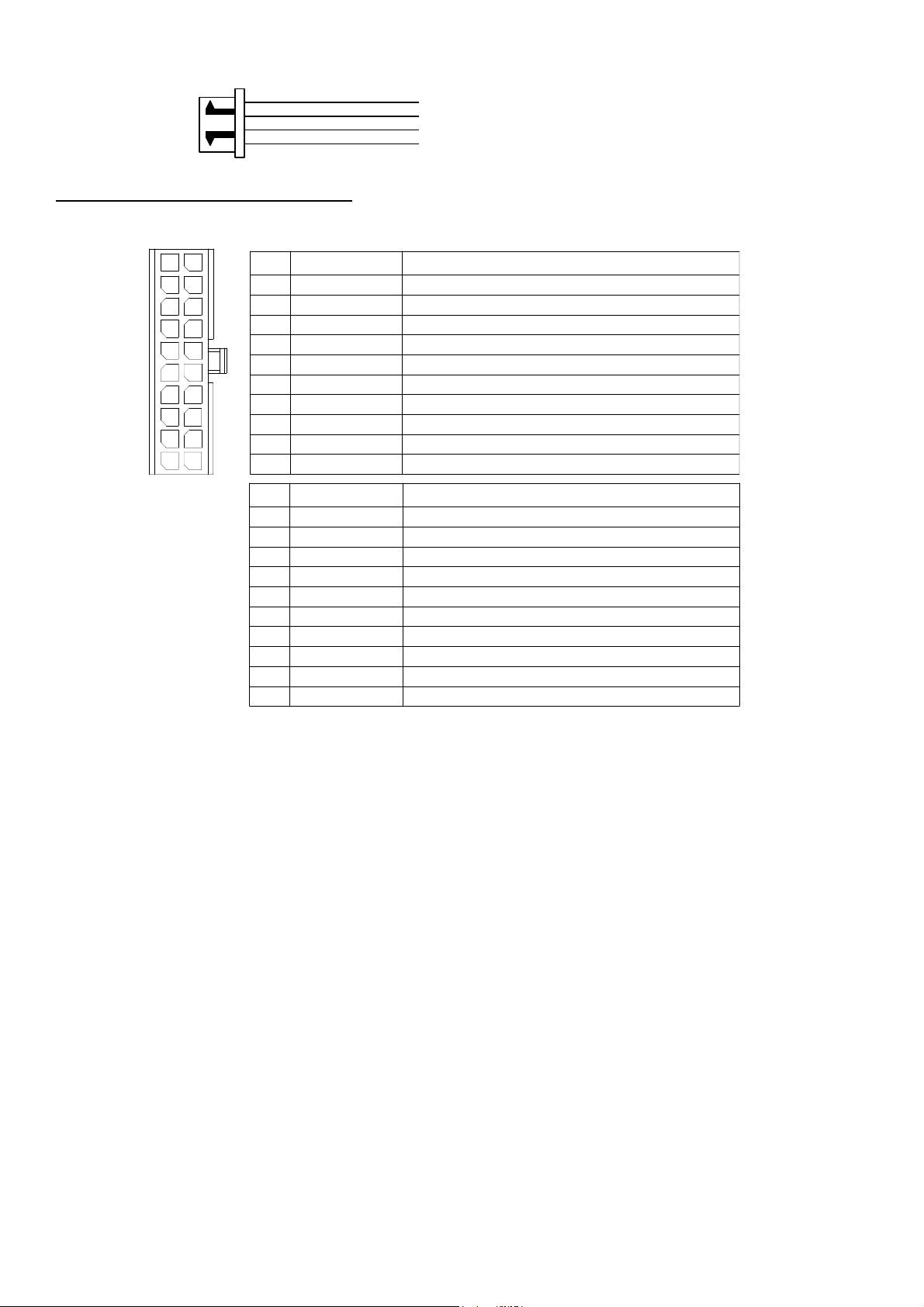
H6: 20 PIN WIRE CONNECTOR 8
H2: SERIAL DATA PORT CONNECTION RS-232 Port 13
H4. 3 PIN DOOR LOCK CONNECTOR (maximum 200 mA output) 13
Negative Trigger Door Lock System
Positive Trigger Door Lock System
Alternating Door Lock System
Vacuum Operate Door Locking System
2 Steps Door Unlock Wire Connection-5 Wires Alternating Lock System
2 Steps Door Unlock Wire Connection- (-) Switched Door Lock System
2 Steps Door Unlock Wire Connection- (+) Switched Door Lock System
THIS PRODUCT IS DESIGNED FOR PROFESSIONAL INSTALLATION ONLY
TABLE OF CONTENTS:
4
6
6
6
6
7
7
7
7
7
7
13
13
13
14
14
14
14
PROGRAMMING & TESTING:
PROGRAMMING THE REMOTE TRANSMITTER
FEATURES PROGRAMMING 14
Alarm Feature “A” Programming 14
Alarm Feature “B” Programming 15
Alarm Feature “C” Programming 17
Channel 4 Timer Control Output Programming
Password Pin Code Setup
Start Feature “D” Programming 19
Start Feature “E” Programming 20
Tachometer Checking Type – RPM Learning & Testing
Voltage Checking Type – Start Timer Set-up & Testing
Timer Checking Type – Start Timer Set-up & Testing
Test Mode
RETURN TO FACTORY DEFAULT SETTING 22
TROUBLE SHOOTING 23
SHUTDOWN DIAGNOSTICS 23
14
17
18
20
21
21
22

TESTING YOUR INSTALLATION 23
Test the Brake shutdown circuit
Test the Hood Pin shutdown circuit
Neutral Start Safety Test
Mechanical Neutral Safety Switch Considerations
Park/Neutral ECM Input
Key In Sensor Circuits
INTRODUCTION
23
23
23
24
24
24
This Remote Starter with Alarm and Keyless Entry System has been designed to be installed on fuel-injected vehicles
with an automatic transmission ONLY
Never
install this remote starter on a manual transmission vehicle.
.
This system must be installed and wired through a safety switch so it will not start in any forward or reverse gear.
Some automatic transmission vehicles mainly older GM vehicles with a purple starter wire have a mechanical-type
park safety switch instead of electrical safety switch. The mechanical type does not interrupt the starter circuit when
the transmission is in any gear and does not offer the 100% level of safety required for remote starting purposes.
Therefore, our system should never be installed on any vehicle that uses a mechanical type park safety switch.
Once you install this system, you must verify that the vehicle will not start in any forward or reverse gear,
regardless of the type of vehicle.
Read the operation manual for operating.
Do not install
any component near the brake, gas pedal or steering linkage.
Some vehicles have a factory installed transponder immobilizer system that can severely complicate the
installation. There is a possibility that this system cannot be installed on some immobilizer-equipped vehicles.
Most vehicles have an SRS air bag system. Use extreme care and do not probe any wires of the SRS system.
Disconnect the car battery before beginning work on the vehicle.
Check behind panels before drilling any holes. Ensure that no wiring harness or other components are located
behind the panels that would otherwise be damaged.
Do not use conventional crimp lock, bullet on any wiring. Poor wiring, i.e. taped joints will possibly introduce
unreliability into the alarm system and may result in false alarms or incorrect operation. We suggest soldering all
connection points.
Install the wiring neatly under carpets or behind trim to prevent possible damage to wires.
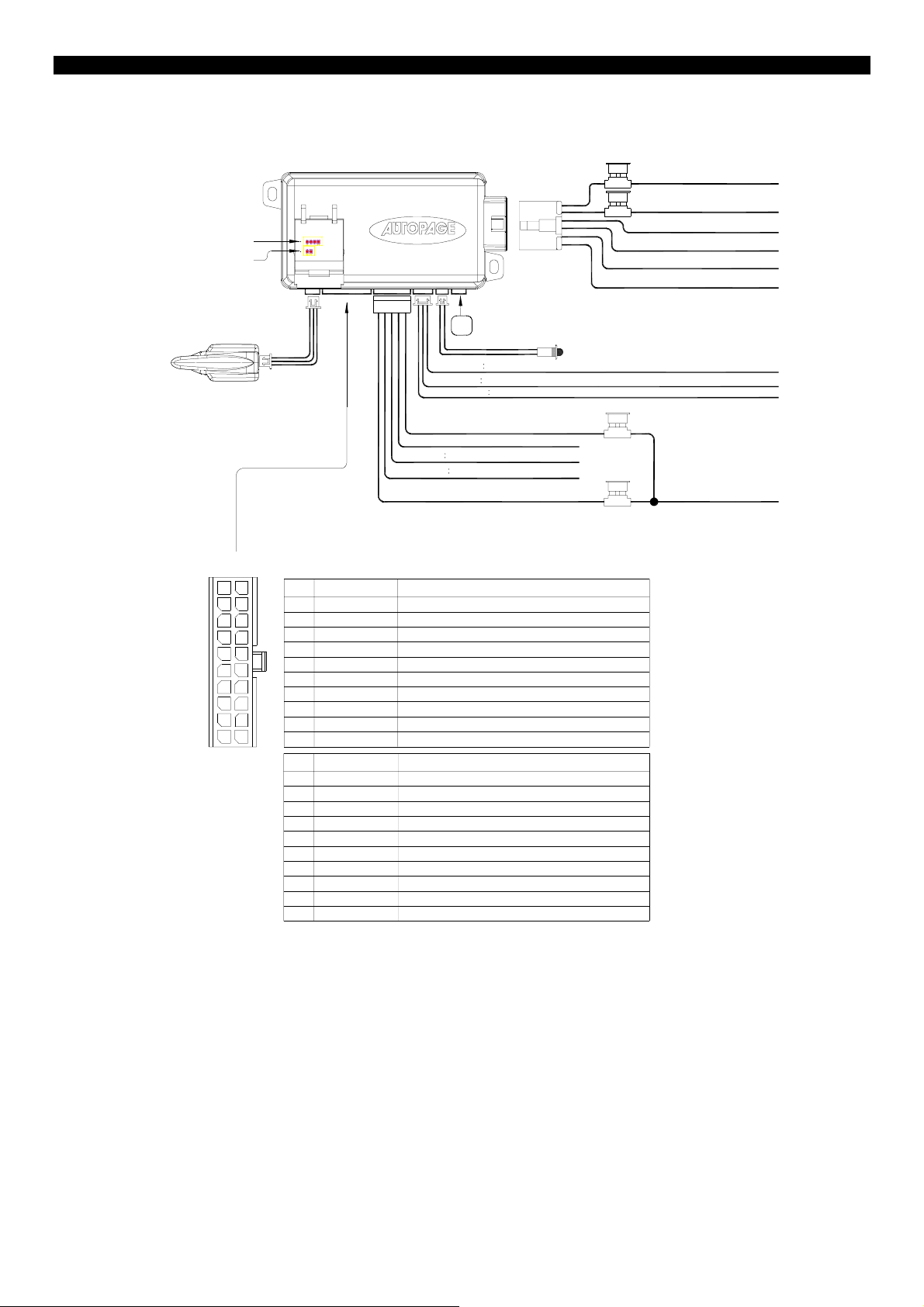
Orange : Sensor #1(Zone4)
Blue : Valet sw Input
Antenna Receiver Assembly(434MHz)
H8
Black
INSTALLATION DIAGRAM
20A Fuse
Red : +12v input
20A Fuse
Red : +12v input
H1
H9
Black
H7
CI3 RS-730
H3
H4
White
H5
H2H6
White
Black
White
DB
I
Blue
(-) Unlock Pulse,(+) Lock Pulse Output
Red +12v Output
Green
(+) Unlock Pulse,(-) Lock Pulse Output
Red/White : Parking Light Relay Power Input
White : Parking Light Relay Output
System Main Gr ound
Black
Brown Siren(+) Output
Red : +12v Battery Power
LED Indicator
15 A Fuse
3A Fuse
Violet : Starter Output
Yellow : Ignition 1 Output
Pink : Ignition 2 Output
Brown : ACC/Heater Output
To Car Battary
10
11
1
12
2
3
13
14
4
5
15
6
16
7
17
8
18
9
19
20
Pin
Brown/Black
1
Gray/Black
2
Pink
3
White/Blue
4
White
5
6
Brown/White
7
Black/Green
Black/White
8
Orange/White
9
White/Red
10
Pin
Blue/Black
11
White/Green
12
Yellow
13
Green
14
Gray
15
Blue
16
White/Violet
17
Violet
18
19
White/Black
Orange
20
Color
Color
Function
Ground Output While Running
Second Starter Output
2-Step Unlock/Factory Disarm/Sensor By-pass
Instant Start And Turn Off Input
Dome Light Control Output
Horn
Output (Programmable)
Channel 4 Programmable Output
Neutral Safety Switch Input
Ground
Output When Disarmed
Tachometer Signal Input
Function
Accessory 2 Control Output
Diesel Wait To Start Input
Ignition 3 Control Output
Zone 3 (-) Negative Door Pin Trigger
Channel 3(Trunk) Output
Zone 2 Negative Hood/Trunk Trigger
(+) Brake Switch Shutdown Input
Zone 3 (+) Positive Door Pin Trigger
(-) Negative Hood Pin Safety Shutdown
Ground
Output When Armed
r
)
g
(+)
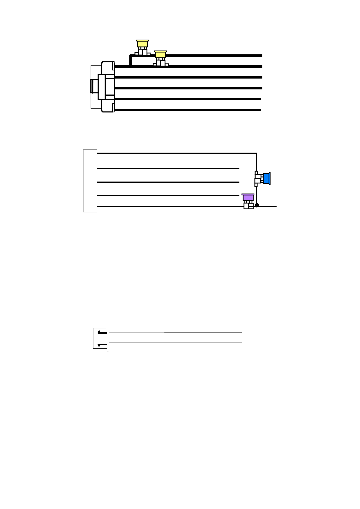
H1 6 PIN HEAVY GAUGE WIRE HARNESS
20A
H5 5 PIN WIRE HARNESS
Red/White: Parkin
White: Parking Light Relay Output
Black:
System Main Ground (-
Brown: Siren(+) Output
20A
Light Relay Power Input
Red: Remote Start Power 1
Red: Remote Start Power 2
Violet: Starter (+) Output
Pink: Ignition 2 (+) Output
Yellow: Ignition 1 (+) Output
Brown: Acc/Heater (+) Output
Red: 12v + Battery Powe
H4. 3 PIN, DOOR LOCK CONNECTOR
1. Blue
3. Green
Wire
Wire
( - ) Unlock Pulse
Lock Pulse
( - ) Lock Pulse
( + ) Unlock Pulse
WIRING
V
Keep wiring away from moving engine parts, exhaust pipes and high-tension cable. Be sure to tape wires that pass
through holes on the firewall to prevent fraying.
CAUTION: Do not connect the wire harness to the control module until all wiring to vehicle is complete.
H1: 6 PIN HEAVY GAUGE WIRING CONNECTIONS:
Remember that what the system does to start a vehicle is to duplicate the functions of the ignition key switch! Below,
we will explain the three basic functions of the ignition switch. Since this installation will require analysis of the ignition
switch functions, we recommend making the three connections below at the ignition switch harness directly.
Violet Wire—Starter Output
Careful consideration for the connection of this wire must be made to prevent the vehicle from starting while in gear.
Understanding the difference between a mechanical and an electrical Neutral Start Switch will allow you to properly
identify the circuit and select the correct installation method. In addition you will realize why the connection of the
safety wire is required for all mechanical switch configurations.
Failure to make this connection properly can result in personal injury and property damage.
In all installations it is the responsibility of the installing technician to test the remote start unit and assure that the
vehicle can not start via RF control in any gear selection other than park or neutral.
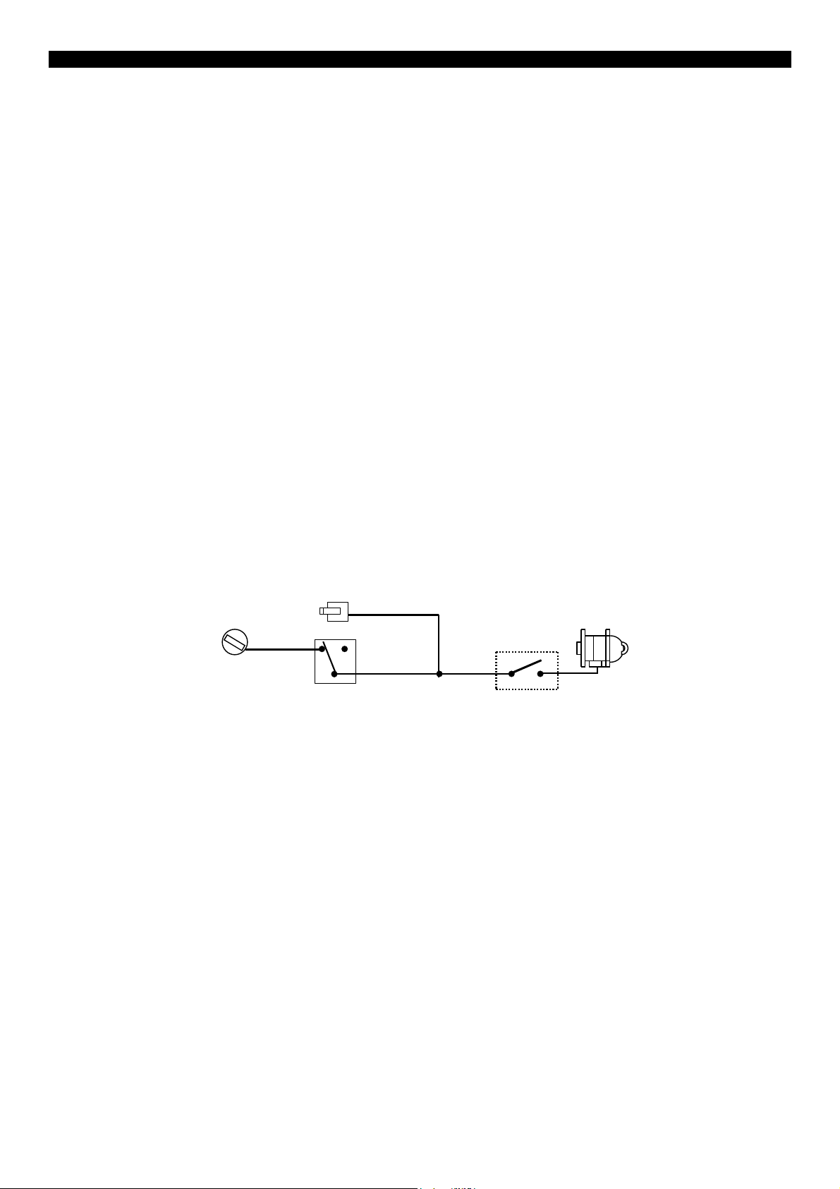
In both mechanical and electrical neutral start switch configurations, the connection of the VIOLET wire will be made
to the low current start solenoid wire of the ignition switch harness. This wire has +12 volts when the ignition switch
is turned to the “START” (CRANK) position only. This wire has 0 volts in all other ignition switch positions.
NOTE
: This wire must be connected to the vehicle side of the starter cut relay (when used). For the electrical neutral
switch configuration, this connection must be made between the starter inhibit relay (when used) and the neutral
safety switch as shown in the following diagram. Failure to connect this wire to the ignition switch side of the neutral
safety switch can result in personal injury and property damage.
DETAILS.
IOLET Wire
“On”
“Off”
“Acc”
Ignition
Switch
“Start”
Start Cut Relay
(When Used)
Red Wire (2) — +12V Power Input
Remove the two 20A fuses prior to connecting these wires and do not replace them until the satellite has been
plugged into the control module. These wires are the source of current for all the circuits the relay satellite will
energize. They must be connected to a high current source. Since the factory supplies (+) 12V to the key switch that
is used to operate the motor, it is recommended that these wires be connected there.
Note: If the factory supplies two separate (+) 12V feeds to the ignition switch, connect one RED wire of the satellite
to each feed at the switch.
Yellow Wire – Ignition 1 Output
Connect the YELLOW wire to the ignition 1 wire from the ignition switch. The ignition wire should receive “12 volts”
when the ignition key is in the “ON” or “RUN” and “START” or “CRANK” position. When the ignition is turned “OFF”,
the ignition wire should receive “0” voltage. The YELLOW wire must be connected.
PINK Wire – Ignition 2 Output
Some vehicles have [2] ignition wires that must be power. Connect the PINK wire to the ignition 2 wire from the
ignition switch. The ignition wire should receive “12 volts” when the ignition key is in the “ON” or “RUN” and “START”
or “CRANK” position. When the ignition is turned “OFF”, the ignition wire should receive “0” voltage. If the PINK wire
is not used, cap the end of the wire.
Brown Wire –Accessory Output (Heater /AC Output)
Connect the BROWN wire to the accessory wire in the vehicle that powers the climate control system.
An accessory wire will show + 12 volts when the ignition switch is turned to the “ACCESSORY” or “ON” and “RUN”
positions, and will show 0 Volts when the key is turned to the “OFF” and “START” or “CRANK” position. There will
often be more than one accessory wire in the ignition harness. The correct accessory wire will provide power to the
SEE NEUTRAL START SAFETY TEST FOR FURTHER
Neutral Safety
Switch
Closed in Park or
Neutral Only
Starter
vehicle’s climate control system. Some vehicles may have separate wires for the blower motor and the air
conditioning compressor. In such cases, it will be necessary to add a relay to power the second accessory wire.
H5: 5 PIN WIRE HARNESS:
RED / WHITE WIRE –PARKING LIGHT RELAY INPUT —
The RED/WHITE wire is the input to the flashing parking light relay. The connection of the RED/WHITE wire will
determine the output polarity of the flashing parking light relay.
If the vehicle you are working on has +12volt switched parking lights, you don’t need connect this wire. This wire is
already connected to +12volt.
If the vehicle’s parking lights are ground switched, cut the RED/WHITE wire, connect the RED/WHITE wire to
chassis ground.
WHITE WIRE — PARKING LIGHT RELAY OUTPUT
(+12 V 10A OUTPUT) —
Connect the WHITE wire to the parking light wire coming from the headlight switch. Do not connect the WHITE wire
to the dashboard lighting dimmer switch. (Damage to the dimmer will result). The limitation of the WHITE wire is 10
AMP max. Do not exceed this limit or damage to the alarm and parking relay will result.
BLACK WIRE — SYSTEM GROUND –
This is the main ground connection of the alarm module. Make this connection to a solid section of the vehicle frame.
Do not connect this wire to any existing ground wires supplied by the factory wire loom, make the connection to the
vehicle’s frame directly.
BROWN WIRE – (+) 2A SIREN OUTPUT –
This wire is provides power to the supplied siren. Connect the Brown wire to the Red wire of the siren. Connect the
Black wire of the siren to a stable chassis ground.
RED WIRE — SYSTEM POWER (+12V CONSTANT) —
The RED wire supplies power to the system. Connect this wire to a stable constant +12 volt source.
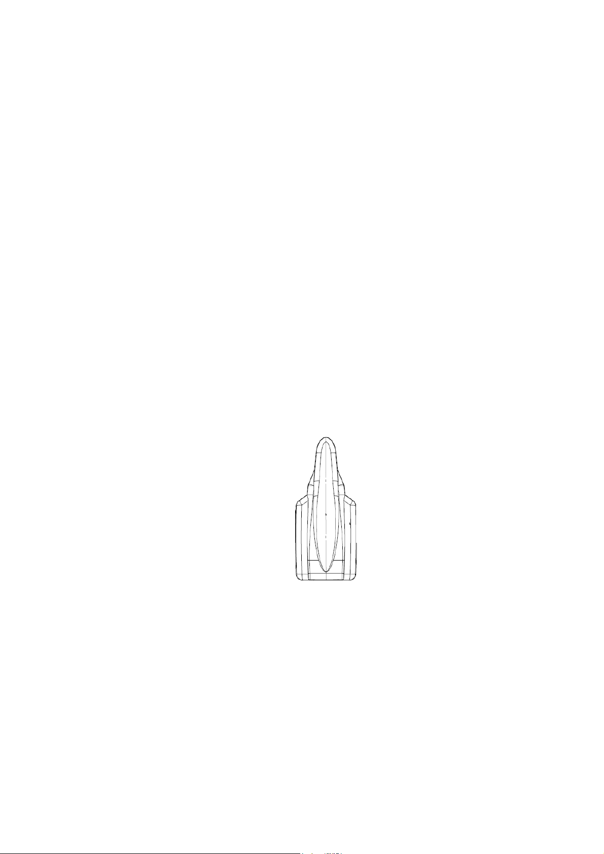
H7. 3-PIN BLACK CONNECTOR. – TWO-WAY TRANSCEIVER/ANTENNA MODULE
The Two-way transceiver/antenna mounting
location should be the upper left or lower left corner
of driver’s windshield. For optimum range we
suggest that the antenna be mounted as shown in
picture to the right. (Antenna tip facing up)
Warning!
Do not mount in such a manner that it obstructs the
driver’s view.
- Remove the protective tape backing.
- Carefully align the two-way transceiver/antenna and apply to windshield.
- Route the black connector wire behind the trim and connect to the two-way transceiver/antenna.
- Connect the other end to the control module.
- Special considerations must be made for windshield glass as some newer vehicles utilize a metal-shielded window glass that
will inhibit or restrict RF reception. In these vehicles, route the two ways transceiver/antenna module away from metallic
shielded window glass as far as possible.
H8. 2 PIN BLUE CONNECTOR FOR THE VALET SWITCH: (Under door on main unit)
Select a mounting location for the switch that is easily accessible to the driver of the vehicle. The switch does not
have to be concealed, however, concealing the switch is always recommended, as this provides an even higher level
of security to the vehicle. Mount the valet switch in a hidden but accessible location. Route the valet switch wires to
the control module.
H3. 2 PIN WHITE CONNECTOR (THE LED STATUS INDICATOR):
The led indicator status should be mounted in a highly visible area such as top of the dashboard, on top of the shifter
console or on the dashboard face. Leave at least 6mm space behind the mounting location for LED housing. Once a
suitable location is chosen, drill a 6mm hole. Run the LED wires through the hole then press the 2 pin LED housing into
place. Route the LED wires to the control module.
H9. 4 PIN ORANGE CONNECTOR 2 STAGE SHOCK SENSOR, ZONE-4, (Under door on main unit)
1. Green Wire / Zone 1 Warn Away Input
2. Blue Wire / Zone 4 Ground Trigger
3. Black Wire / Ground
4. Red Wire / +12Volts
H-6: 20 PIN WIRE CONNECTORS:
11
10
1
12
2
3
13
14
4
5
15
6
16
7
17
8
18
9
19
20
Pin
1
2
3
4
5
6
7
8
9
10
Pin
11
12
13
14
15
16
17
18
19
20
H6/1 BROWN/BLACK WIRE: 200 mA (-) Ground Output When Running.
This wire provides a negative output during the remote start process. It can be used to operate by-pass modules that may be
required in your installation. This wire will provide ground once the remote start process has been initiated and will remain
grounded while the engine is running.
H6/2 GRAY/BLACK WIRE: 200 mA (-) Second Starter Output.
This line can be used if a second starter line is needed. Some vehicles require a two-starter line to remote start. This wire
provides a negative output that will work the same way as the Violet starter line in connector H1.
H6/3 PINK WIRE – (-) 200mA Programmable Output
2 Steps Unlock Output (Factory default setting)
(See Alarm Feature C – 1 Programming)
The 2 steps unlock feature will work for the most fully electronic door lock circuit. The vehicle must have an electronic door lock
switch (not the lock knob or key switch), which locks and unlocks all of vehicle's doors. When wired for this feature, press the
disarm (or unlock) button one time will disarm the alarm and unlock the driver's door only. If, press disarm (or unlock) button two
times within 3 seconds, the alarm will disarm and all doors will unlock.
Factory Security Disarm Signal Output –
This wire is designed to disarm a factory installed security system. This wire sends a negative (-) 1 seconds pulse upon a
remote start and remote door unlocking. Some factory systems must be disarmed to allow remote starting. In most cases, this
wire may be connected directly to the factory alarm disarm wire. The correct wire will show negative ground when the key is
used to unlock the doors or trunk. This wire is usually found in the kick panel area in the wiring harness coming into the car body
from the door.
Start Status (Shock Sensor By-Pass Control) Output–
This wire is designed to by-pass shock sensor module. This wire will supply an output at all times the remote start is operating
plus an additional 3 seconds after the remote start unit turn off.
Key Sensor By-Pass Output –
This output is for a Key Sense wire by-pass that some Chrysler and Toyota vehicles need to activate remote start. This wire
comes on when remote start is activated and stays on for 20 seconds.
Color
Brown/Black
Gray/Black
Pink
White/Blue
White
Brown/White
Black/Green
Black/White
Orange/White
White/Red
Color
Blue/Black
White/Green
Yellow
Green
Gray
Blue
White/Violet
Violet
White/Black
Orange
Function
Ground Output While Running
Second Starter Output
2-Step Unlock/Factory Disarm/Sensor By-pass
Instant Start And Turn Off Input
Dome Light Control Output
Horn
Output (Programmable)
Channel 4 Programmable Output
Neutral Safety Switch Input
Ground
Tachometer Signal Input
Output When Disarmed
Function
Accessory 2 Control Output
Diesel Wait To Start Input
Ignition 3 Control Output
Zone 3 (-) Negative Door Pin Trigger
Channel 3(Trunk) Output
Zone 2 Negative Hood/Trunk Trigger
(+) Brake Switch Shutdown Input
Zone 3 (+) Positive Door Pin Trigger
(-) Negative Hood Pin Safety Shutdown
Ground
Output When Armed
 Loading...