

Page 1
s
r
MODEL TRX72
REMOTE ENGINE STARTER
WITH ALARM SYSTEM
INSTALLATION MANUAL
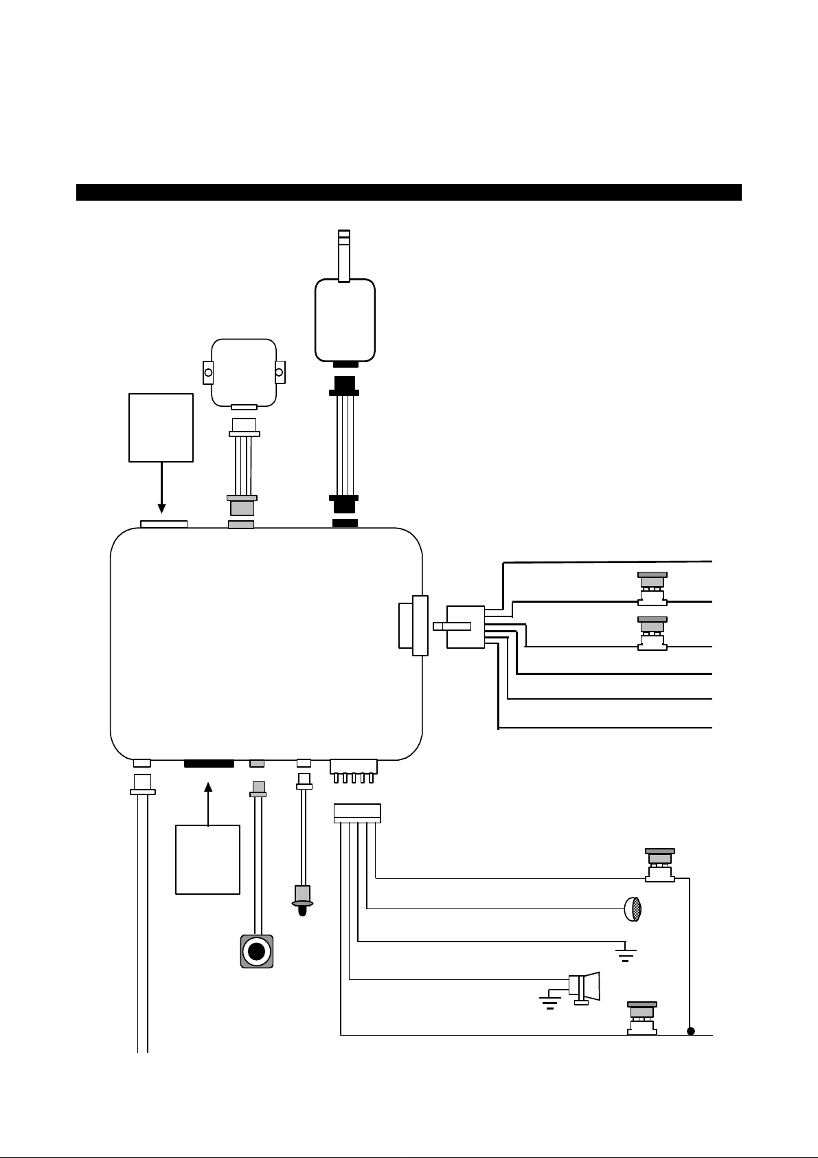
INSTALLATION DIAGRAM
Two Way
Transceive
Antenna
Dual Zone
Shock
Sensor
H7
8 Pin Black
Connector
for Input
Connection
H 6
3 Pin
White
3. Green: (-) Lock Pulse. Or (+)Unlock Pul
H 7
8 Pin
Black
1. Blue: (-) Unlock Pulse. Or (+)Lock Pulse
H 8
4 Pin
Orange
H 5
6 Pin
White
H5
6 Pin White
Connector
for Output
Connection
H 4
2 Pin
Blue
VALET
SWITCH
H 3
2 Pin
White
LED
Ind icator
H 9
4 Pin
Black
H 2
5 Pin
White
H 1
6 Pin
White
1. Red / White:
2. White:
3. Black:
4. Brown:
1. Violet:
2. Red:
3. Red:
4. Yello w:
5. Pink:
6. Brown:
Parking Light Relay Power input
Parking Light Relay Output
Ground to Vehicle Frame
Positive Outpu t to Siren
Starter Output
+12V Input
+12V Inp u t
Ignition 2 output
Ignition 1 output
ACC/Heater Output
20A
Fuse
20A
Fuse
10A Fuse
3A Fuse
+12V Input
5. Red:
1
Page 2
p
(
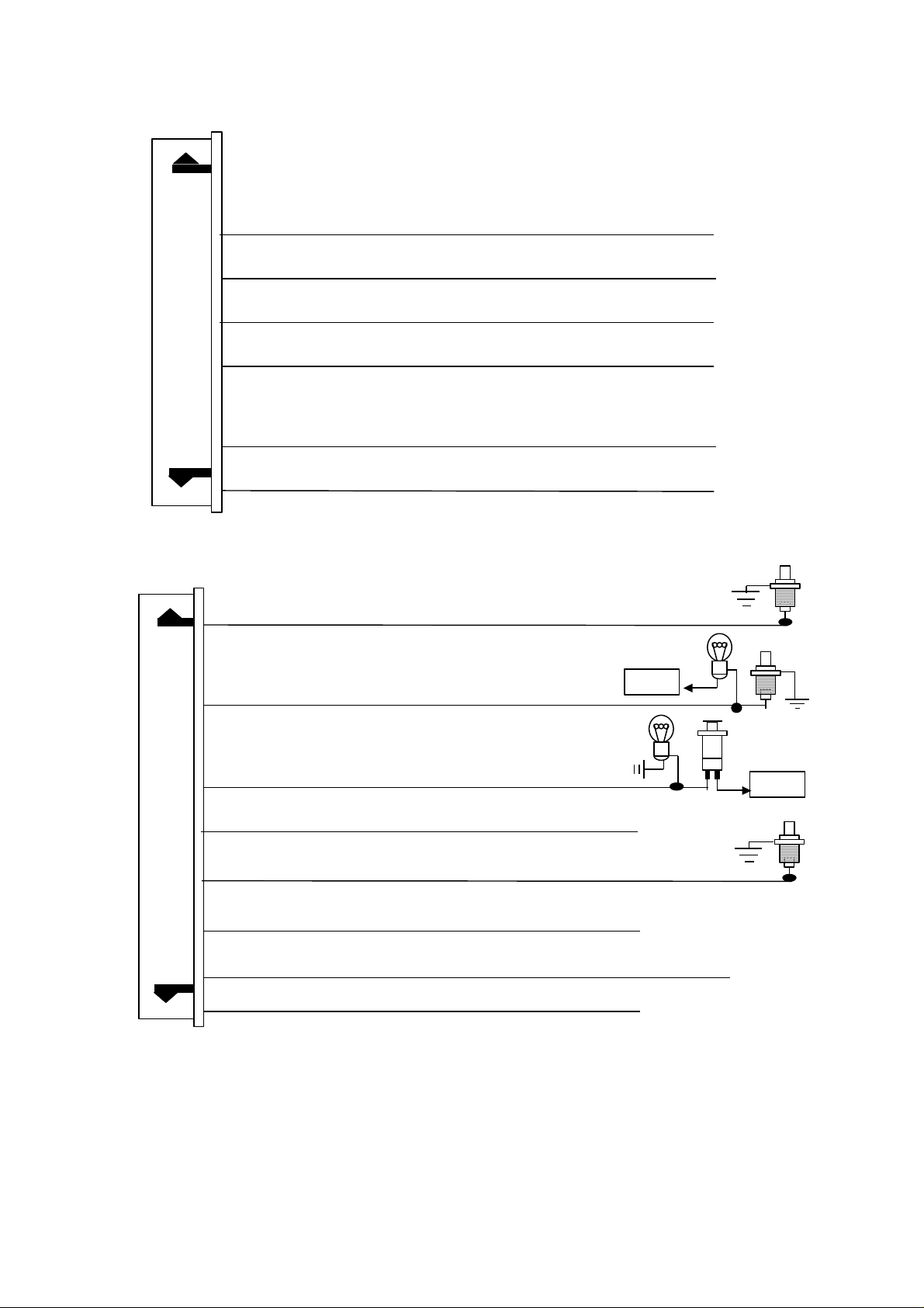
#H5 6 PIN WHITE CONNECTOR FOR OUTPUT CONNECTION
1. W hite
Wire: (-) 2 0 0 mA P rogram mable output
Dome Light C ontrol Output (F a ctory Default se tting)
Or Horn Output
Or Factory Security Rearm Signal Output
Or Ground Out
2. Yellow
3. Black / Green
4. Gray
5. Pink
Wire: (-) 200 m A Ignition 3 C ontrol Output
Wire: (-) 2 00 mA Time Cont rol C h annel 4 Output
Wire: (-) 2 00 mA Chan n e l 3 (T runk) Output
Wire: (-) 200 m A Programmable output
ut During Start (Crank).
2-Step Do or U nlock Output (F ac tory Default setting)
Or Factory Security Disarm Signal Output
Or Start Status (S ho c k S ens o r B y pass Co ntrol) Outp ut
6. Orange
Wire:
-) 500mA Groun ded Output When Armed
#H7. 8 PIN BLACK CONNECTOR FOR INPUT CONNECTION:
1. Blue
Wire:
Zone 2
Instant Trigger Ground Input
2. Green
3. Violet
4. White/Blue
5. White/Black
6. Black/White
7. White/Violet
8. White/Red
IMPORTANT NOTE:
is not used.
Wire:
Wire:
Zone 3
Zone 3
Wire: (-) Ins ta nt St art a n d Turn O ff Inp ut.
Wire: (
Wire: (
Wire: (
Wire: Tach. Signal Input
Directly connect the H7/6 BLA CK/WHITE wire to the “GROUND” when this wire
Negative Door Pin Trigger Input:
Positive Door Pin Trigger
) Negative Safety Sh ut D own Input for Hood pin switch
-
) Neu tral Safety Switch Input &
-
) Remote Start Toggle Sw itch Input
(
-
) Pos itive Safety Shut Down Input for B r a ke sw itc h .
+
+12V
+12V
2
Page 3

INTRODUCTION
INSTALLER WARNINGS
This Remote Starter with Alarm System is designed to be installed on fuel injected vehicles ONLY.
For automatic transmis sion vehicle, this system m ust be inst alled and wired through a saf ety switch it will
not start in any forward or reverse gear.
Some automatic transmission vehicle [mainly older GM vehicles with a purple starter wire] have a
mechanical-type park safety switch instead of electrical safety switch. The mechanical type does not
interrupt the starter circuit when the transmission is any gear and does not off er the 100% level of safety
required for remote s tarting purposes. Therefor e, our system should never be installed on any vehicle that
uses a mechanical type park safety switch.
For automatic transm ission vehicle, once you install this system, you must verify that the vehicle will not
start any forward or reverse gear. Regardless of the type of vehicle.
Read operation manual for operating and programming routine.
Do not install any component near the brake, gas pedal or steering linkage.
Some vehicles have a factor y installed transponder imm obilizer system that can severely com plicate the
installation. There is possibility that this system can not be installed on some immobilizer equipped vehicles.
Most vehicles have an SRS air bag system. Use extrem e care and do not probe any wires of the SRS
system.
Disconnect the car battery before connecting work on the vehicle.
Check behind panels before drilling any holes. Ensure that no wiring harnes s or other com ponents are
located behind the panels that would otherwise be damaged.
Use conventional crimp lock, bullet on any wiring. Poor wiring, i.e. taped joints will possibly introduce
unreliability into the alarm system and may result in false alarms or incorrect operation.
Install wiring neatly under carpets or behind trim to prevent possible damage to wires.
For the wire operates the current mor e than 10A. W e suggest soldering all c onnection point. Do not use
crimp lock type connectors or wire nuts.
WIRING
Keep wiring away from moving engine parts, exhaust pipes and high-tension cable. T ape wires that pass
through holes on the firewall to prevent fraying. Watches out sharp edges that may damage wires and
causes short circuit.
CAUTION: Do not connect the wire harness to the control module until all wiring to vehicle is complete.
H1: 6 PIN HEAVY GAUGE WIRING CONNECTION:
Remember that the system does to start a vehicle is duplicate the functions of the ignition key switch!
Below, we will explain the three basic functions of the ignition switch. Since this installation will require
analysis of the ignition switch functions, we recom m end mak ing the three connections below at the ignition
switch harness directly.
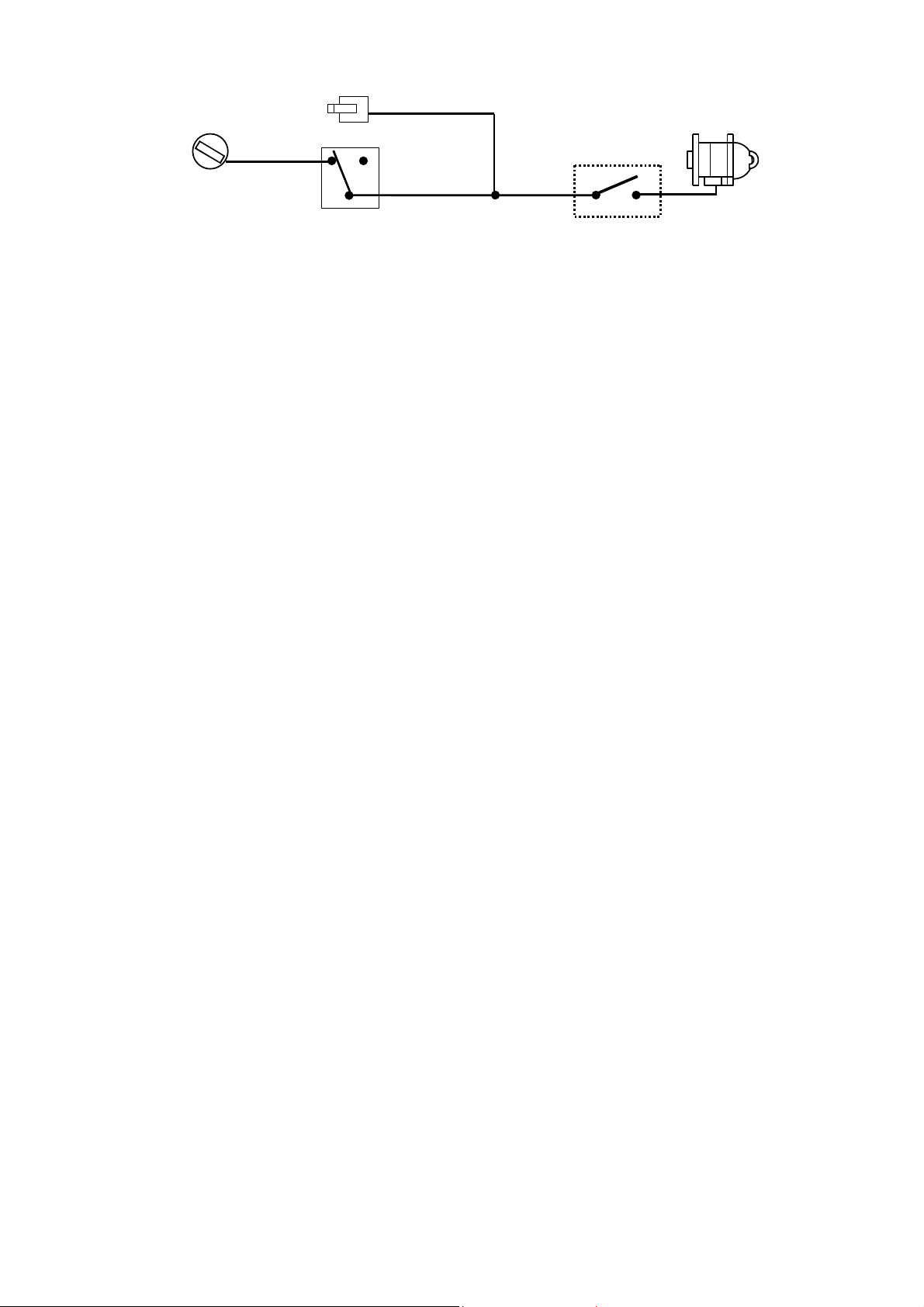
H1/1. Violet Wire – Starter Output
Careful consideration for the connection of this wire must be made to prevent the vehicle from starting
while in gear. Understanding the difference between a m echanical and an electrical Neutral Start Switch
will allow you to properly identify the circuit and select the cor rect installation method. In addition you will
realize why the connection of the safety wire is required for all mechanical switch configurations.
Failure to make this connection properly can result in personal injury and property damage.
In all installations it is the responsibility of the installing technician to test the rem ote start unit and assure
that the vehicle can not start via RF control in any gear selection other than park or neutral.
In both mechanical and electrical neutral star t switch conf igurations, the c onnection of the VIOLET wire will
be made to the low current start solenoid wire of the ignition s witch har nes s . T his wire have +12 volts when
the ignition switch is turned to the “START” (CRANK) position only. This wire have 0 volts in all other
ignition switch positions.
NOTE: This wire must be connected to the vehicle side of the starter cut relay (when used). For the
electrical neutral switch configuration, this connec tion must be made between the starter inhibit relay (when
used) and the neutral safety switch as shown in the following diagram.
Failure to connect this wire to the ignition switch side of the neutral safety switch can result in personal
injury and property damage. SEE NEUTRAL START SAFETY TEST FOR FURTHER DETAILS.
3
Page 4
V
“Off”
“Acc”
Ignition
Switch
“On”
“Start”
IOLET Wire
Neutral Safety
Switch
Starter
Start Cut Relay
(When Used)
Closed in Park or
Neutral Only
H1/2 & H1/3. Red Wire (2) – +12V Power Input
Remove the two 20A fuses prior to c onnecting these wires and do not replace them until the satellite has
been plugged into the control module. These wires are the source of c urrent for all the circuits the relay
satellite will energize. They must be connected to a high current sour ce. Since the f actor y supplies ( +) 12V
to the key switch that is used to operate the motor, it is recommended that these wires be connected there.
Note: If the factory supplies two separate (+) 12V feeds to the ignition switch, connect one RED wire of the
satellite to each feed at the switch.
H1/4. Yellow Wire – Ignition 1 Output
Connect the YELLOW wire to the ignition 1 wire from the ignition s witch. The ignition wire should receive
"12 volts" when the ignition key is in the "ON" or “RUN” and "START" or “CRANK” position. W hen the
ignition is turned "OFF", the ignition wire should receive "0" voltage.. The Yellow wire must be
connected.
H1/5. Pink Wire – Ignition 2 Output
Some vehicles have [2] ignition wires that must be power. Connect the PINK wire to the ignition 2 wire from
the ignition switch. The ignition wire should receive "12 volts" when the ignition key is in the "ON" or “RUN”
and "START" or “CRANK” position. W hen the ignition is turned "OFF", the ignition wire should receive "0"
voltage. If the PINK wire is not used, cap the end of the wire.
H1/6. Brown Wire –Accessor y Output (Heater /ACC Output)
Connect the BROWN wire to the accessory wire in the vehicle that powers the climate control system.
An accessory wire will show + 12 volts when the ignition switch is turned to the “ACCESSORY” or “ON” and
“RUN” positions, and will show 0 Volts when the key is turned to the “OFF” and “START” or “CRANK”
position. There will often be mor e than one accessory wire in the ignition har ness. The c orrect accesso ry
wire will power the vehicle’s climate control system. Som e vehicle m ay have separate wires for the blower
motor and the air conditioning compressor. In such cases , it will be necessary to add a relay to power the
second accessory wire.
H2: 5 PIN WIRE HARNESS:
H2/1. Red / White Wir e – Par king Light Relay Input --
The RED/WHIT E wire is the input to the flashing parking light relay. The connection of the RED/WHITE
wire will determine the output polarity of the flashing parking light relay.
If the vehicle you are working on has +12volt switched parking lights, you don’t need connect this wire. This
wire already connected to +12volt.
If the vehicle’s parking lights are ground switched, cut the RED/W HIT E wire, c onnect the RED/WHITE wire
to chassis ground.
H2/2. W hite Wire –Parking Light Relay Output (+12 V 10A Output) --
Connect the WH ITE wire to the parking light wire coming from the headlight switch. Do not connect the
WHIT E wire to the dashboard lighting dim mer switch. ( Damage to the dim mer will result) . The lim itation of
the WHIT E wire is 10 AMP max. Do not exceed this limit or damage to the alarm and parking relay will
result.
H2/3. Black Wire – System Ground –
This is main ground connec tion of the alar m m odule. Mak e this c onnection to a solid s ection of the vehicle
frame. Do not connect this wire to any existing ground wires supplied by the factory wire loom, mak e the
connection to the vehicle's frame directly.
H2/4. Brown Wir e – Sir en Drive Programmable Output – (See Alarm Feature III - 1 Programming)
This is the positive (+) output connec tion for the s iren. Curr ent capacity is 2 amps . Mak e connection to the
(+) red wire from the siren. Make the (-) black wire coming from the siren to a good chassis ground.
H2/5. Red W ir e –System Power (+12V Constant) --
The RED wire supplies power to the system. Connect this wire to a constant +12 volt source.
H3. 2 PIN WHITE CONNECTOR FOR THE LED STATUS INDICATOR:
The led indicator status should be m ounted in a highly visible area such as top of the dashboard, on top of
the shifter console or on dashboard face. Leave at least 6m m s pace behind the m ounting location for LED
housing. Once a suitable location is chos en, drill a 6mm hole. Run the LED wires through the hole then
press the 2 pin LED housing into the place. Route the LED wires to the control module.
4
Page 5
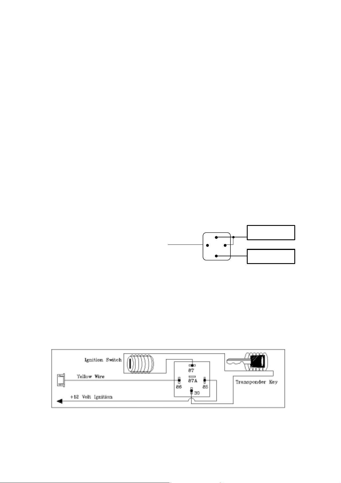
H4. 2 PIN BLUE CONNECTOR FOR THE VALET SWITCH:
Select a mounting location for the s witch that is easily accessible to the driver of the vehicle. The switch
does not have to be concealed, however, concealing the switch is always recomm ended, as this provides
an even higher level of security to the vehicle. Mount the valet switch in a hidden but accessible location.
Route the valet switch wires to the control module.
H5: 6-PIN MINI WHITE CONNECTOR WIRE HARNESS:
H5/1. White Wire –(-) 200ma Programmable Output.
Dome Light Control Output (Factory Default Setting)—
This wire becomes grounded when the dome light controls circuit active. The current capacity of this wire is
200mA. This wire can control the operation of the interior lights. An optional 10 Amps relay can be used to
this system for interior lights operation.
a). Upon disarming, the interior lights will remain on for 30 seconds.
b). If the vehicle is violated, the interior light will flash for the same duration as the siren.
Horn Output– See Alarm Feature III - 2 Programming)
This wire is provided to use the existing vehicle's horn as the alarm system's optional's warning audible
device. It's a transistorized low current output, and should only be connected to the low current ground
output from the vehicle's horn switch. When the system is triggered, the horn will sound.
Factory Security Rearm Signal Output– (See Alarm Feature III - 2 Programming)
This wire is designed to rearm a factory installed security system. This wire will supply a pulse whenever
the remote start times out or is shut dowm using the transmitter and remote door locking..
Ground Output During Star t ( Cr ank) –
(See Alarm Feature III - 2 Programming)
This wire will provide a 200 mA ground output while the starter output of the remote start unit is active. This
output can be used to activate the Crank Low/Bulb Test wire found in some GM vehicles. This wire is also
referred to as the ECM wake up wire in some vehicles.
H5/2. Yellow Wire – (-) 200ma Ignition 3 Output –
This wire provides a 200mA (-) ground output that becomes active 4 seconds before the remote start unit
initialize, and remains grounded while running.
Ignition 3 output:
Some newer vehicles use a third ignition wire
which is required to start and keep the vehicle’s
engine running. If this is the case, wire an IGN 3
relay (not supplied) as shown below:
Do not connect any vehicle circuits together, they
are isolated for a resaon.
Transponder interfacing using relay:
If the vehicle has transponder system installed, you will need to by-pass the system while the vehicle is
operating under the control of the Remote Start Unit. To do this:
1. You will need a transponder key that's already programmed to the vehicle.
2. Remove the trim around the ignition switch.
3. Wrap a thin (28 - 30awg) wire tightly around ignition switch 6 to 8 times and secure it.
4. About 6"down line make another loop of approximately 2"diameter.
5. Place the key inside this loop and secure it to the loop.
6. Connect on end of the (28 - 30awg) wire to pin (87) of the relay module.
7. Connect the other end of the loop wire to Pin (30) of relay module.
8. Connect the pin (86) of the relay module to the ignition wire from the ignition switch.
9. connect the pin (85) of the relay module to the H5/2 Yellow wire of 5-pin mini white connector.
Yellow Wire
30
87
87a
8586
+ 12 V Constant
Fused 25A Capable
Ignition 3 Wire From
Ignition Key Switch
GM VATS KEY OVERRIDE:
If the vehicle has the General Motor VAT S system installed, you will need to by-pass the system while the
vehicle is operating under the control of the Remote Start Unit. To do this:
1. Measure the resistance of the resistor pellet on the ignition key then select a resistor within 5% of the
key’s value.
5
Page 6
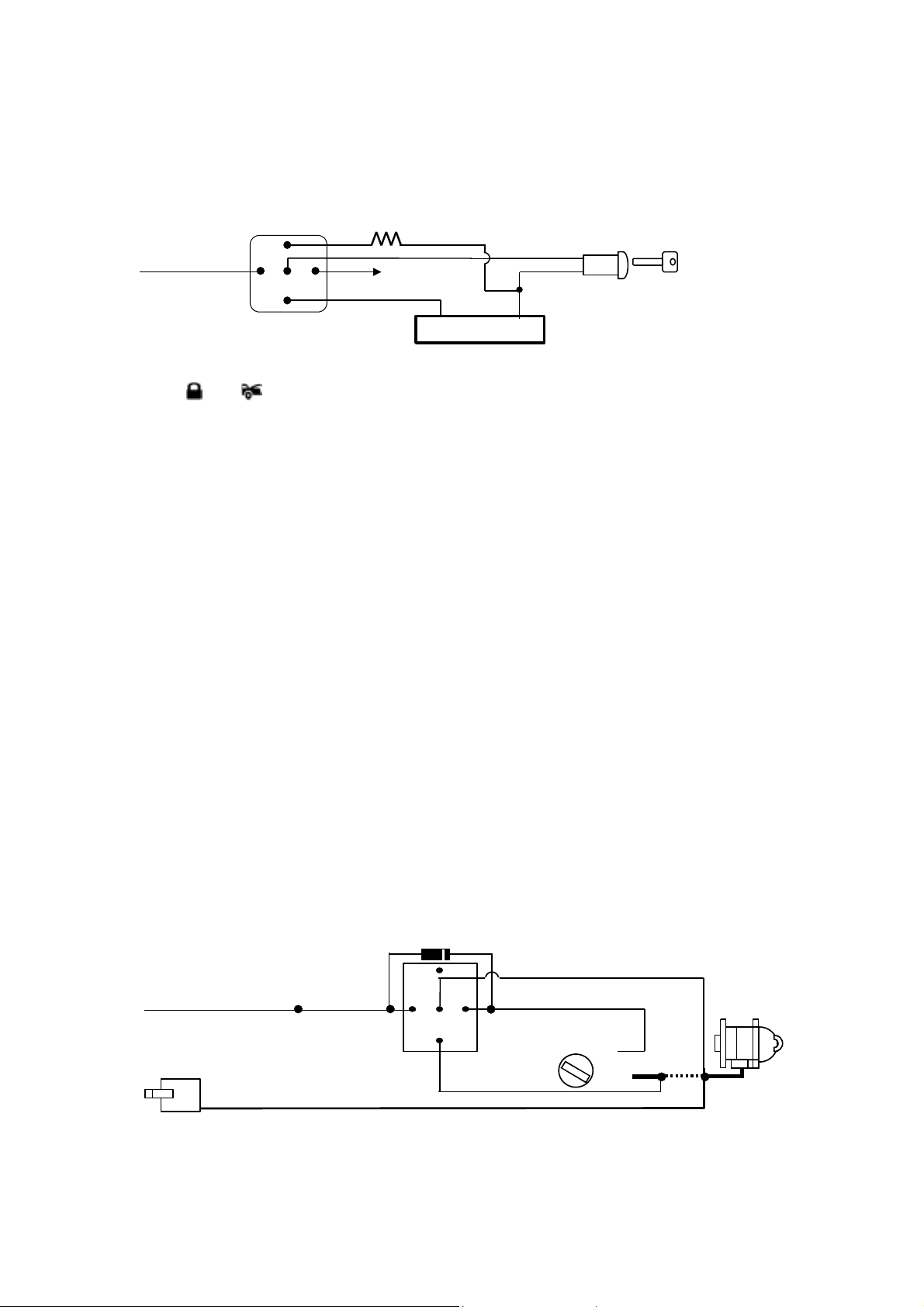
2. Loc ate the pair of VAT S wires in the vehicle, usually a pair of thin gauge wires running fr om the ignition
(#2)
switch to the VATS control module.
3. Connect the YELLOW wire from Remote Start Unit to TERMINAL #85 of an external relay. Connect
terminal #86 of the relay to a fused +12 volt.
4. Cut (#1) wire (as shown), and connect the ignition switch side of the cut wire to term inal #87a of the
relay. Connect the other side of the (#1) wire to terminal #30.
5. Connect the previously selseced resistor from terminal #87 to the second(#2) wire (as shown).
Matching Re si stor
YELLO W wire
85
87
87a 86
30
To + 12 V
VATS control Module
VAT wire (#1)
VAT wire
Ignition
Switch
H5/3 Black / Green Wire – (-) 200mA Tim er Control Channel 4 Output –
This wire is built-in user-programmable timer output provides a ground through this wire. Press the
transmitter
and buttons at the same time. You may program the built-in timer to send a ground
signal for any time interval between 1 second and 2 minutes. For instance, this timer output m ay be used
to turn on the headlight with the remote control. Also on certain BMW, Mercedes Benz, Jaguar and
Volkswagen cars, you can use this unique timed output to allow rem ote closure of all power window and
sunroof without the need for an external module! (See Alarm Feature III – 4 Programming) (Factory
default setting on momentary grounded)
H5/4 . Gray Wire – Channel 3 (Trunk Release) Output
This will become a 1 second pulse ground by activate channel 3 on transmitter for two seconds, the current
capacity of this wire is 200 mA. This feature allows you to remote control trunk release or other electric
device.
H5/5. Pink Wire –(-) 200ma Programmable Output (See Alarm Feature III - 3 Programming)
2 Steps Unlock Output – (Factory Default Setting) –
The 2 steps unlock feature will work f or the most fully electronic door lock c irc uit. T he vehic le must have an
electronic door lock switch (not the lock knob or k ey switch), which locks and unlock s all of vehicle's doors.
When wired f or this featur e, press the disar m ( or unlock ) button one time will disarm the alarm and unloc k
the driver's door only. If, press disarm (or unlock ) button two times within 3 seconds , the alarm will disarm
and all doors will unlock.
Factory Security Disarm Signal Output–
This wire is designed to disarm a factory installed security system. This wire sends a negative (-) 1 seconds
pulse upon a remote start and rem ote door unlocking. Some f actory systems must be disarmed to allow
remote starting. In most cases , this wire may be connected directly to the factory alarm disarm wire. The
correct wire will show nagative ground when the key is used to unlock the doors or trunk. This wire is
usually found in the kick panel area in the wiring harness coming into the car body from the door.
Start Status (Shock Sensor Bypass Contr ol) Output –
This wire is designed to by-pass shock sensor module. This wire will supply an output at all times the
remote start is operating plus an additional 3 seconds after the remote start unit turn off.
H5/6 Orange Wire –(-) 500ma Grounded Output When Armed --
This wire will become grounded when the alarm is armed. The current capacity of this wire is 200mA. This
output can control starter disable, when an intrusion is detected and the system is triggered. The vehicles
prevent from any unauthorized starting.
IN4003 Diode
White wire
Yellow wire to
Ignition Switch
“Off”
“Acc”
“On”
“Start”
Starter
Cut
X
: ORANGE wire
H5/6
from control module
VIOLET wire (Starter output)
H1/1
form Heavy Gauge wire harness
87
Orange wire
86
85
87a
30
Red wire
H7: 7 PIN MINI BLACK CONNECTOR :
H7/1. Blue W ire – Ground Instant Trigg er I nput --
This wire is the ground trigger input wire for hood/trunk pin switches.
H7/2. Green Wire – Negative Door Switch Sensing Input --
6
Page 7
This wire is the ground trigger input wire for negative door pin switch. This wire is connection for
p
"grounding" type factory door pins locate the "common wire" that connec ts the door pin s witches . Make the
connection of the GREEN Wire here.
H7/3. Violet Wire – Positive Door Switch Sensing Input --
This wire is the positive trigger input wire for pos itive door pin switch. T his wire is connection f or "positive"
type factory door pins(typical FORD MOTOR). Locate the "c ommon wire" for all door pins and m ake the
connection of the VIOLET Wire here.
H7/4 Whit e / Blue Wire –(-) Instant Start & Turn O ff Input –(See Alarm Feature III - 5 Programming)
This wires activates and turns off the remote starter each time it sees a momentary ground signal.
Normally only used for testing during installation or when activating the module from an after-market
system.
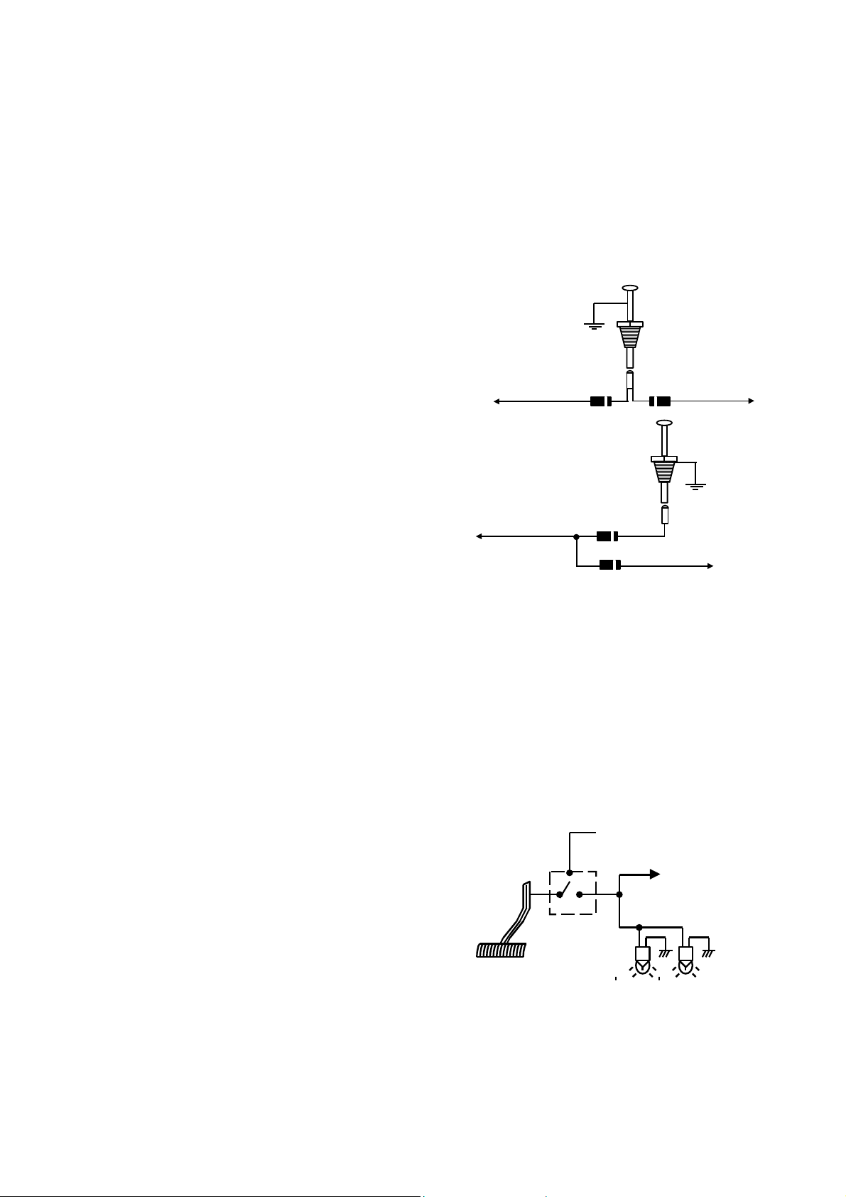
H7/5. W hite/Black W ir e – Negative Safety Shut Down Input –
The W HITE/BLACKE wire provides an instant shutdown
for the remote start, whenever it is grounded. Connect
the wire to the hood pin switch previously installed. This
wire must be routed though a gromm et in the f irewall and
connected to the hood pin switch. If the pin switch is to be
used with an alarm system, connect this wire with diode.
To: White/Black Wire /
Negative safety
Hood Pin Switch
To: Alarm instant
trigger Blue wire
Diode Diode
Hood Pin Switch
Important! This connec tion is a safety wire and must
be connected as shown and tested as specifiled. Failure
to do so may result in personal injury or property
damage. See detail of wiring in the following diagram.
This wire may also be used if the vehicle brake light
circuit switches ground to the brak e lights. An isolation
diode must be used for ground switched brake light
circuits and must be connected to the output of the
brake switch.
White/Black
To:
Negative safety
Wire /
Diode
To Vehicle
Brake Switch
H7/6. BLACK/WHITE W ir e – ( -)Remote Start Enable Toggle Switch Input —
— (-)Neutral Safety Switch Input —
When the BLACK/WHITE wire is gr ounded, the remote star t unit is operable. W hen this wire is open f rom
ground, the remote start is disable.
1. The optional “remote start toggle switch” can be added on to temporarily disable the Remote Start
Device, it can prevent the vehicle from being remote started accidentally. This feature is useful if the
vehicle is being serviced or stored in an enc losed area. To disable the rem ote start, move the optional
remote start enable toggle switch to the OFF position. To enable the r emote start, move the optional
remote start enable toggle switch to the ON position.
2. If needed, This wire can connect to the PARK/NEUTRAL switch in the vehicle. (See the TESTING
YOUR INSTALLATION GUIDE)
IMPORTANT NOTE: Directly connect the BLACK/WHITE wire to the “GROUND” when this w ire is
not used.
H7/7. W hite/Violet Wir e – Positive Safety Shut Down Input
This wire provides an instant shutdown for the remote
start, whenever it gets +12volts. If the brak e lights switch
in the vehicle switches +12 volts to the brake light circuit,
connect this wire to the output side of the brake s witch.
This will allow the remote start to shut down if an attem pt
is made to operate the vehicle without the key while
running under the control of the remote start. In most
vehicles, in order to shift gear, the brak e pedal must be
depressed. The brak e input will in turn cause the rem ote
start unit to shut off. See below diagram.
Switch closes
When brake is
ress
de
+12 volts from fuse box
To White/ Violet
wire
Brake light bulbs
H7/8. W hit e /Red Wire – Tach. Signal connection—
Note: You should connect this wire if you program the Start Feature II – 2 to “Engine checking TACH.”
otherwise not to connect this wire and tap the end.
Note: No connection of this wire is required, if you use the voltage or timer checking type mode.
This input provides the remote start system with information about the engine’s revolutions per minute
(RPM). It can be connected to the negative side of the c oil in vehicle with conventional coils. In m ulti-coil
and high energy ignition system locating a proper signal may be more difficult. Once connected,
7
Page 8
To test for a tach. wire, a m ulti-meter capable of test AC voltage must be used. The tach. wire will show
(+)
between 1V and 6V AC at idle, and will increase as engine RPM increases. In m ulti-c oil ignition s ystem, the
system can learn individual coil wire. Individual coil wires in a m ulti-coil ignition system will regis ter lower
amounts of AC voltage. Also, if neces sary, the system can us e a fuel inj ector c ontrol wire for engine speed
sensing. Common locations for a tach. wire are the ignition coil itself, the back of the gauges, engine
computers, and automatic transmission computers.
IMPORTANT! Do not test tach. wires with a test light or logic probe. The vehicle will be damaged.
How to find a tachometer wire with your multi-meter
1. Set the ACV or AC voltage (12V or 20V is fine.)
2. Attach the (-) probe of the meter to chassis ground.
3. Start and run the vehicle.
4. Probe the wire you suspect of being the tach. wire with the red probe of the meter.
5. If this is the correct wire the meter will read between 1V and 6V.
Important Note: You must program the “Tach Signal” before trying to remote start.
H8. 4 PIN ORANGE CONNECTOR FOR 2 STAGE SHOCK SENSOR
4. Green
3. Blue
2. Black
1. Red
Wire / +12Volts
Wire /
Wire /
Zone 1
Zone 4
Wire / Neg ative
War n Away Input
Ground Trigger
H9. BLACK 4-PIN CONNECTOR. – TWO-WAY TRANSCEIVER/ANTENNA MODULE
The Two-way transceiver/antenna mounts on the location above the belt line (dashboard) of the vehicle for best reception. We suggest you mount it on the lower left or upper left-hand side of windshield. Warning! Do not mount in such a manner that it obstructs the driver’s view.
- Remove the protective tape backing.
- Carefully align the two-way transceiver/antenna and apply to windshield.
- Route the black connector wire behind the trim and connect to the two-way transceiver/antenna.
- Connect the other end to the control module.
- Special considerations must be made for windshield glass as some newer vehicles utilize a metallic
shielded window glass that will inhibit or restrict RF reception. In these vehicles, route the two ways
transceiver/antenna module away from metallic shielded window glass as far as possible.
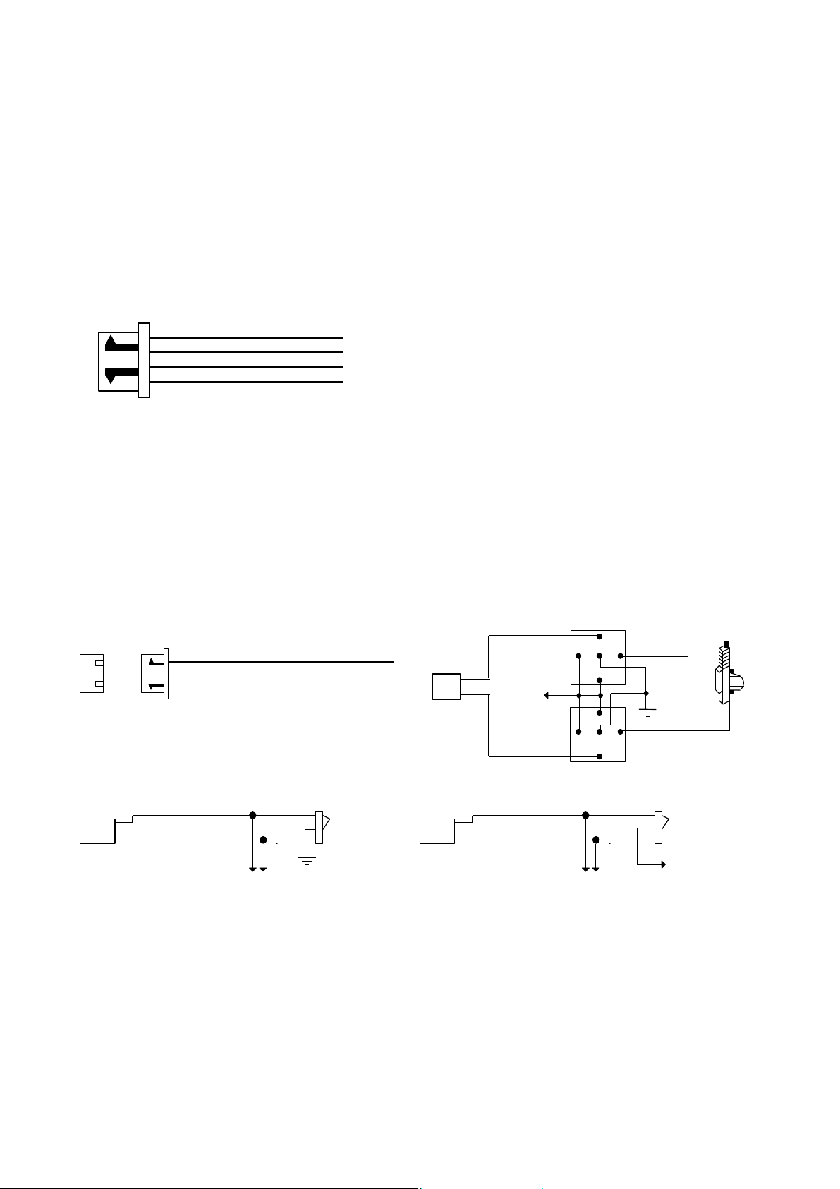
H6. 3 PIN DOOR LOCK CONNECTOR:
I
INSTALL NEW DOOR LOCK MOTOR
Blue Wire
Green Wire
NEGATIVE TRIGGER DOOR LOCK SYSTE
Blue Wire Door Unlock
Green Wire Door Lock
( - ) Unloc k P u lse
Lock Pulse
( - ) Lock P u lse
( + ) Un lock P ulse
To Exiting
Door Lock Relay
Locking
Master
Switch
3 Pin
Plug To
Alarm
POSITIVE TRIGGER DOOR LOCK SYSTEM
Blue Wire
+12V
Green Wire
Blue Wire Door lock
Green Wire Door Unlock
86
87
30
87a
85
86
87a
87
30
85
To Exiting
Door Lock Relay
Locking
Master
Switch
+ 12V
8
Page 9
X
e
e
)
5-WIRE ALT E R N ATING DOOR LOC K
Cut the Existing
X
Lock Wire
To Door
+12V
Lock
Motor
3 Pin Plug
To Alarm
Green Wire
87
87
Blue Wire
87a
87a
86
85
86
85
Master Door
Lock Switch
30
30
To Slave Door
Lock switches
Cut the Existing
Unlock Wire
+12V
Splice
Splice
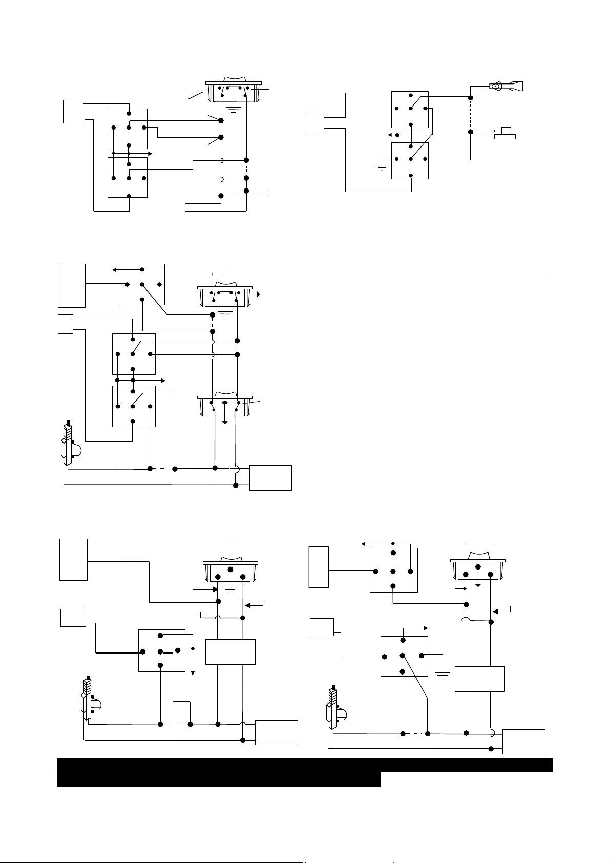
2 STEP DOOR UNLOCK WIRE CONNECTIO N FOR
5 WIRE ALTERNATING DOOR LOCKS
:
H5/5
6-Pin
Plug
From
Alarm
:
H6
3 Pin
Plug
To
Alarm
+ 12V
Pink Wire
Green Wi re
Blue Wire
87
86
85
87A
30
Cut the Unlock Wire
85
87
30
87A
86
85
30
87
87A
86
OEM Door Master Lock
Unlock
+ 12V
+12V
Lock
x
Cut the Existing
Lock Wire
OEM Slave
Door Lock
Switch
LockUnlock
+12V
VACUUM OPERATED CENTROL LOCKIN G
3 Pin
Plug To
Alarm
Green Wire
+12V
Blue Wire
86
87a
30
87
85
86
87a
87
30
85
X
Door Switch
Cut
Compressor
VACUUM OPERATED DOOR LOCKING SYSTEM:
TYPICAL OF MERCEDES BENZ AND AUDI.
Locate the wire under the driver's kick panel. Use the
voltmeter connecting to ground, verify that y ou have th
correct wire with the doors unlocked, the voltmeter will
receive "12 volts". Lock the doors and the voltmeter wi
read "0 volt". Move the alligator clip to +12V and the
voltmeter will receive "12 volts". Cut this wire and mak
connections. Be sure to program door lock timer to
3.5 seconds.(See Alarm Feature
II – 1 Programming.
OEM Driver’s
Door Lock Motor
Cut Existing Unlock
To All Other
Door Lock
Motors
2 STEP DOOR UNLOCK WIRE CONNECTION FOR
GROUND SWITCHED DOOR LOCK S
:
H5/5
6-Pin
Plug
From
Alarm
:
H6
3 Pin
Plug
To
Alarm
Pink Wire
Green Wire
Door Lock
Blue Wire
Door Unlock
OEM
Door Lock
Motor
Existing Neg.
Unlock Wire
87
86
87A
30
Cut Existing Unlock
OEM Door Master Lock Switch
85
+ 12V
OEM Door
Lock Relay
X
LockUnlock
Existi ng Neg.
Lock Wire
To All Other
Door Lock
Motors
2 STEP DOOR UNLOCK WIRE CONNECTION FOR
POSITIVE SWITCHED DOOR LOCKS
:
H5/5
6-Pin
Pink Wire
Plug
From
Alarm
:
H6
3 Pin
Plug
To
Alarm
ROGRAMMING
A. PROGRAMMING THE REMOTE TRANSMITTER:
+12V
86 85
30
Blue Wire Door Lock
Green Wire
Door Unlock
OEM Driver's
Door Lock
Motor
87
87A
Existing Pos.
Unlock Wire
87
87A
86
85
30
X
Cut Existing Unlock
OEM Door Master Lock Switch
+ 12V
+ 12V
OEM Door
Lock Relay
LockUnlock
Existing Pos .
Lock Wire
To All Other
Door Lock
Motors
9
Page 10
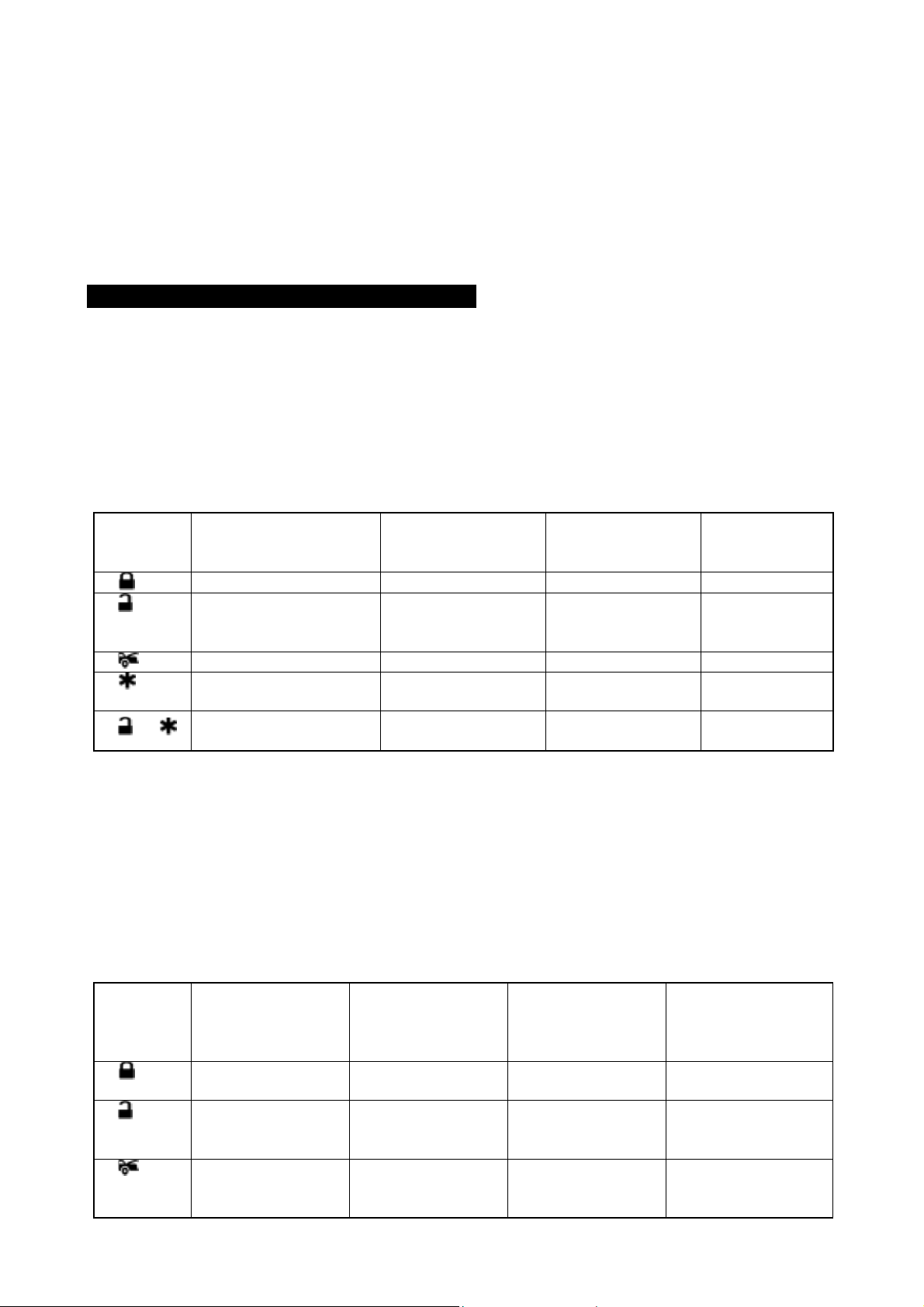
Note: This mode will only retain the last 4 remote tr ansmitters program med. If the transm itter mem ory is
exceeded, the security system will start deleting transmitters from memory in chronological order.
1. Turn the Ignition 'switch ‘OFF/ON’ 3 TIMES and stay in ON position. Within 15 seconds.
2. Push the Valet switch 3 times and holding in on 3rd push until a long c hirp is hearing then release the
valet switch. You are now in the Transmitter programming mode.
3. Press and hold any button of the transmitter until the siren responds with a confirming chirp, indicating
the signal has been stored into memory.
4. If you have additional transmitters (up to 4) that need to be programmed, repeat step 3 for each
transmitter.
Exit: Turn Ignition to 'OFF' position, or leave it for 15 seconds. A 3 long c hirps & 3 parking light f lashes to
confirm exit.
B. ALARM FEATURES PROGRAMMING:
ALARM FEATURE “I” PRORAMMING:
1. Turn the Ignition 'switch ‘ON/OFF’ 3 TIMES and stay in OFF position.
2. Push the Valet switch 2 times and holding in on 2
release the valet switch. You are now in the Alarm feature ‘I’ programming mode.
3. Press and release the transmitter button ‘A’ corresponding to the feature ‘A’ you want to change.
a. The siren chirps and LED pause will indicate newly setting.
b. The system would advance to [2] LED flash, [2] chirp. (The f actory default settings is always [1] LED
flash, [1] chirp.)
4 Depress the transmitter button ‘A’ again to change the feature again. Simple keep re-depressing the
transmitter button ‘A’ again until the module advances to your desired setting.
5. Depress the transmitter button ‘B’ corresponding to the feature ‘B’ you wants to program.
Press
Transmitter
Button
1
2
One Chirp /
LED one pulse
Factory Default Setting
Two Chirps /
LED two pulse
All chirps on Siren chirp on only Horn chirp on only All chirps off
Active arming Passive arming
without passive door
locking
3
4
5 +
Automatic Rearm on Automatic Rearm off
Instantly Door Ajar
Warning
Without Car-jack mode Active Car-jack mode Passive Car-jack
45 seconds delay
Door Ajar Warning.
Exit: T urn Ignition to 'ON' position, or leave it for 15 seconds . A 3 long chirps & 3 parking light flashes to
confirm exit.
3 / 45 seconds Delay Door Ajar Warning:
This feature controls the error chirp that is generated if the system is armed with the door trigger active.
This useful in a vehicle that has a long dome light delays after the door has been closed. If the system is
armed before the dome light has turned off, the security system will generate the door trigger error chirp.
Use this feature to disable the door open error chirp.
nd
push until one chirp with a long chirp is hearing then
Three Chirps /
LED three pulse
Four Chirps /
LED four pulse
Passive arming with
passive door
locking.
mode
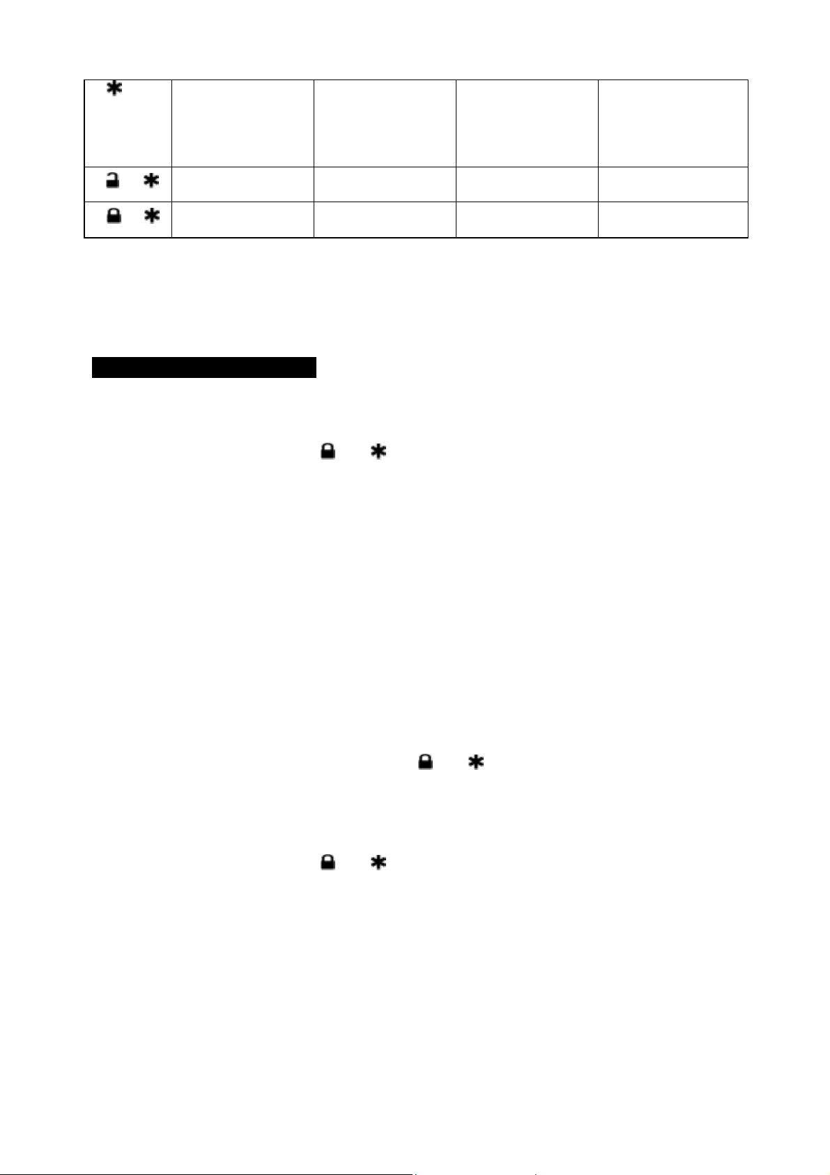
ALARM FEATURE “II” PRO RAMMING:
1 . Turn the Ignition 'switch ‘ON/OFF’ 3 TIMES and stay in OFF position.
2 . Push the Valet switch 4 times and holding in on the 4
then release the valet switch. You are now in the Alarm feature ‘II’ programming mode.
3 . Press and release the transmitter button ‘A’ corresponding to the feature ‘A’ you want to program.
Press
T
ransmitte
Button
One Chirp / LED
r
one pulse
Factory Default
Two Chirps / LED
two pulse
Setting
1
2
0.8-second Door
lock pulses.
Ignition controlled
door locks &
3.5-second Door
lock pulse.
Ignition controlled
door locks only
unlocks
3
Door lock before
start
Door lock after
shut-down
th
push until two ch irps with a long chirp is hearing
Three Chirps / LED
three pulse
Four Chirps / LED
four pulse
Double pulse unlock Door lock with
“Comfort Feature”
Ignition controlled
door unlocks only
Without ignition
controlled door locks
& unlocks
Door lock before
Without this feature
start and Door lock
after shut-down
10
Page 11
4
Pathway illumination
feature “off”
Parking light “on” for
30- second upon an
unlock signal
Parking light “on” for
30- second upon an
unlock signal &
10-second upon a
lock signal.
5 +
+
6
Disable the out of
range check.
Override Without
Password Pin Code
Enable the out of
range check
Override With
Password Pin Code
Exit: T urn Ignition to 'ON' position, or leave it for 15 seconds . A 3 long chirps & 3 parking light flashes to
confirm exit.
Comfort Feature:
Some Vehicles have a special “COMFORT feature”. When you lock the door with the key, you just have to
keep on turning the key on the door about 5 or 7 seconds and the window will close directly.
If your vehicle with “COMFORT feature” and you wish the door being locked and the window being closed
automatically at the same time by remote control, You can set the alarm feature II-1 “with comfort feature”.
Password Pin Code Setup:
Enter:
1. Turn the Ignition 'switch ‘ON/OFF’ 3 times and stay in OFF position.
2. Push the Valet switch 4 times and holding in on the 4
th
push until two c hirps with a long chirp is hearing
then release the valet switch. You are now in the Alarm feature ‘II’ programming mode.
3. Press and release the transm itter
and button at the same time twice, [2] LED flash, [2] s iren/horn
chirp to indicate your are in features “Password Pin Code Programming mode”.
4. Within 5 seconds, begin to enter your chosen first 9ths digit by pressing and releasing the valet switch
from 1 – 9 times.
5. Within 15 seconds of the last entered 9ths digit, turn the Ignition switch to “ON” position.
6. Within 15 seconds, enter your chosen second 9ths digit by pressing and releasing the valet switch from
1 – 9 times.
7. Finish by turning the ignition switch to “OFF” position.
If the new password code was accepted, the unit would report back the newly entered code, by flashing the
LED, first indicating the first digit code has been memorized, pause and then the second digit code. The
unit will report the new code three times with a one-second’s pause between each code.
Note: If 15 seconds of inactivity expire, or if the ignition switch is turned “ON” for more then 5 seconds
during of above steps, the unit will revert back to the last successfully stored code. A [3] long chirps to
confirm exit. Will
revert back to the last successfully stored code
Delete Password Pin Code / Override Without Password Pin Code (Factory default setting):
1. Turn the Ignition 'switch ‘ON/OFF’ 3 times and stay in OFF position.
2. Push the Valet switch 4 times and holding in on the 4
th
push until two c hirps with a long chirp is hearing
then release the valet switch. You are now in the Alarm feature ‘II’ programming mode.
3. Within 15 seconds, press and hold the transmitter
and button at the same time for 3 seconds. A
one long chirps to confirm Deleted the Password Pin Code.
Example: To program the Password Code 92, you would;
1. Turn the Ignition 'switch ‘ON/OFF’ 3 times and stay in OFF position.
2. Push the valet switch 4 times and holding in on the 4
th
push until two c hirps with a long ch irp is hearing
then release the valet switch. You are now in the Alarm feature ‘II’ programming mode.
3. Press and release the transmitter
and button at the same time twice, [2] LED flash, [2] s iren/horn
chirp to indicate your are in features “Password pin code programming mode”.
4. Within 5 seconds, press and release the valet switch 9 times.
5. Within 15 seconds of the last entered 9ths digit, turn the Ignition Switch to “ON” position.
6. Within 15 seconds press and release the valet switch two times.
7. Turn the Ignition Switch to “OFF’ position.
You will note the LED flashing nine times, pause and then flash two times, pause. This pattern will be
repeated three times indicating the new code (92) has been accepted and stored in memory.
Exit: Press any button of the transmitter to exit the password pin set up mode.
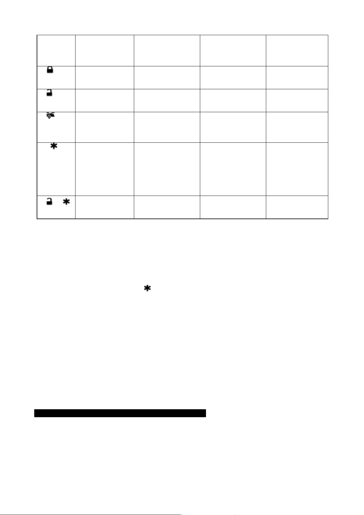
ALARM FEATURE “III” PRO RAMMING:
1. Turn the Ignition 'switch ‘ON/OFF’ 3 TIMES and stay in OFF position.
2. Push the Valet switch 6 times and holding in on the 6
hearing then release the valet switch. You are now in the Alarm feature ‘III’ programming mode.
3. Press and release the transmitter button ‘A’ corresponding to the feature ‘A’ you want to program.
th
push until three chirps with a long chirp is
11
Page 12
Press
Transmitter
Button
1
2
3
4
5 +
Exit: T urn Ignition to 'ON' position, or leave it for 15 seconds . A 3 long chirps & 3 parking light flashes to
confirm exit.
Ground Output During Start (Crank) = This wire will provide a 200mA ground output while the starter
output of the remote start unit is active. This output can be used to activate the Crank Low/Bulb Test wire
found in some GM vehicles. This wire is also referred to as the ECM wake up wire in some vehicles.
Channel 4 Timer Control Output Programming.
1. Turn the Ignition 'switch ‘ON/OFF’ 3 TIMES and stay in OFF position.
2. Push the Valet switch 6 times and holding in on the 6
hearing then release the valet switch. You are now in the Alarm feature ‘III’ programming mode.
3. Press and release the transm itter
your are in features “Channel 4 Timer Programming mode”.
4. Press and hold the valet switch, the timer will immediately start.
5. When the desired interval has passed, release the valet switch. One long chirp for confirmation.
(Set to any interval between 1 second and 2 minutes)
Note 1:
If your built-in timer controls window/sunroof closure in your car DO NOT change the timer setting! This
requires installer-only programming. Changing the value will adversely effect operation and may cause
damage.
Note 2:
Momentary output = The momentary output selection will output a negative signal from the Channel 4
(5/6) output immediately when the channel 4 (5/6) button is pressed and will continue until the button is
release.
Latched output = The latched output selection will output a negative signal as soon as the Channel 4 (5/6)
button is pressed and will continue until the button is pressed again.
Latched output / reset with ignition = The latched / reset with ignition output selection operates just like
the latched output but will reset or stop when the ignition is turned on.
One Chirp /
LED one pulse
Factory Default
Setting
H2/4 Brown Wire =
Constant Siren
output
H5/1 White Wire =
Dome light Output
H5/5 Pink Wire =
2-Step Door
Unlock Output
H5/3 Black / Green
Wire Channel 4
Output =
Momentary output
H7/4 White / Blue
Wire =
1 pulse activate
Two Chirps /
LED two pulse
H2/4 Brown Wire =
5-second pulse Siren
output
H5/1 White Wire =
Horn Output
H5/5 Pink Wire =
Factory Security
Disarm Signal Output
H5/3 Black / Green
Wire Channel 4
Output =
Latched output
H7/4 White / Blue
Wire =
2 pulse activate
Three Chirps /
LED three pulse
H2/4 Brown Wire =
H5/1 White Wire =
Factory Security
Rearm Signal Output
H5/5 Pink Wire =
Start Status (Shock
Sensor By-Pass
Control) Output
H5/3 Black / Green
Wire Channel 4
Output =
Latched output and
reset with ignition
“on”
H7/4 White / Blue
Wire =
3 pulse activate
Four Chirps /
LED four pulse
Horn Output
H5/1 White Wire =
Ground Output
During Start (Crank)
H5/3 Black / Green
Wire Channel 4
Output =
Timer programming
(set to any interval
between 1 second
and 2 minutes.)
th
push until three chirps with a long chirp is
button 4 times, [4] LED flas hes, [4] siren/horn chirps to indicate
REMOTE START FEATURE PROGRAM MODE.
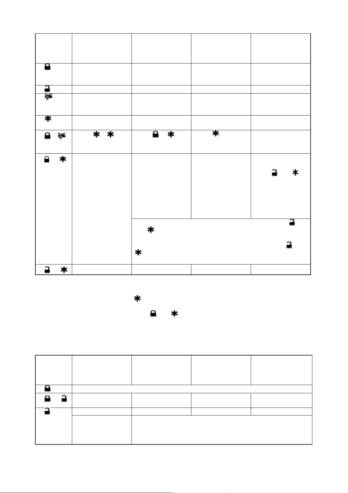
START FEATURE “I” PRORAMMING:
1. Turn the Ignition 'switch ‘ON/OFF’ 3 TIMES and stay in OFF position.
2. Push the Valet switch 8 times and holding in on the 8
then release the valet switch. You are now in the Start feature ‘I’ programming mode.
3. Press and release the transmitter button ‘A’ corresponding to the feature ‘A’ you want to program.
th
push until four c hirps with a long chirp is hear ing
12
Page 13
Press
T
ransmitte
Button
1
2
3
4
+
5
6 +
+
7
Exit: T urn Ignition to 'ON' position, or leave it for 15 seconds . A 3 long chirps & 3 parking light flashes to
confirm exit.
SAFE START (Child safety mode)
Factory defaults setting to press the
Programming this feature to eliminate an accidental remote start, when kids enter this transmitter, it
requires: The user presses the transmitter
One Chirp /
r
LED one pulse
Factory Default
Setting
Gasoline Engine Diesel Engine and
10 minutes run time 20 minutes run time 30 minutes run time 5 minutes run time
Factory alarm
disarm with channel
3 on
Constant parking
light output
Press
button = Activate
Remote Start.
The Vehicle without
Turbo (The system
Cannot be Arm with
the engine running)
3 Hour Time start 2 Hour Time Start
-
Two Chirps /
LED two pulse
10 seconds warn-up
timer
Without this feature
Flashing parking
light output
Press
button = Activate
Remote Start.
The Vehicle has
aftermarket Turbo
timer installed:
The system Can be
Arm with the engine
running and the
shock sensor will be
bypass as long as
the engine running.
Five chirps = Built-in Turbo Timer Control is Active / Press
and
minutes.
Six chirps = Built-in Turbo Timer Control is Active / Press
minutes.
button twice to start the vehicle.
+
buttons at the same time to control Engine running three
buttons at the same time to control Engine running five
and buttons at the same time to start the vehicle.
Three Chirps /
LED three pulse
Diesel Engine and
15 seconds warn-up
timer
Press
Activate Remote
Start.
The Vehicle has
aftermarket Turbo
timer installed:
The system Can be
Arm with the engine
running and the
shock sensor will be
bypass for three
minutes
button =
Four Chirps /
LED four pulse
Diesel Engine and
20 seconds warn-up
timer
Built-in Turbo Timer
Control is Active:
Press
buttons at the same
time to control
Engine running one
minute.
and
and
START FEATURE “II” PRORAMMING:
1. Turn the Ignition 'switch ‘ON/OFF’ 3 TIMES and stay in OFF position.
2. Push the Valet switch 10 times and holding in on the 10
hearing then release the valet switch. You are now in the Start feature ‘II’ programming mode.
3. Press and release the transmitter button ‘A’ corresponding to the feature ‘A’ you want to program.
Press
T
ransmitte
Button
1
2
3
+
One Chirp /
r
LED one pulse
Factory Default
Setting
Exit the programming mode. (3 long chirp & 3 parking light flashes to confirm this exit.)
Engine Checking
TACH.
RPM learning
Start Timer:
0.6-second
Two Chirps /
LED two pulse
Engine Checking
Voltage
0.8-second (2 chirps), 1.0-second (3 chirps), 1.2-second (4 chirps),
1.4-second (5 chirps), 1.6-second (6 chirps), 1.8-second (7 chirps),
2.0-second (8 chirps), 3.0-second (9 chirps), 4.0-second (10
chirps),
th
push until five chirps with a long chirp is
Three Chirps /
LED three pulse
Engine Checking
OFF
Four Chirps /
LED four pulse
13
Page 14
4
5
-
6 +
Low check level for
“Engine Checking
TACH” mode or
Hi check level for
“Engine Checking
Voltage” mode
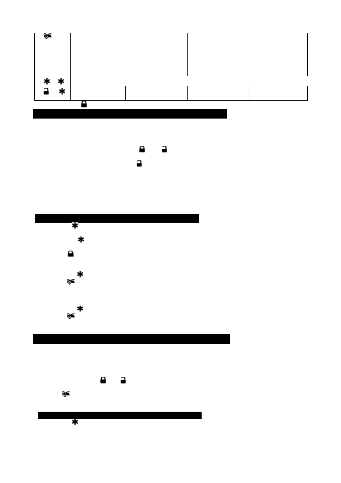
Start / Stop the system for TESTING & ADJUSTMENT
Without Shock
sensor Test Mode
Hi check level for
“Engine Checking
TACH” mode or
Low check level for
“Engine Checking
Voltage” mode
With Shock Sensor
Test Mode
Exit: Press the button on the transmitter. A 3 long chirps & 3 parking light flashes to confirm exit.
ENGINE CHECKING TACH. / RPM LEARNING
Important Note: You must program the “Tach Signal” before trying to remote start.
1. Turn the Ignition switch ‘ON/OFF’ 3 TIMES and stay in OFF position.
2. Push the Valet switch 10 times and holding in on the 10
th
push until five chirps with a long chirp is
hearing then release the valet switch.
3. Press and release the transmitter
and buttons at the same time once to set the “Engine
Checking TACH.” [1] LED flash, [1] chirp to confirm this setting.
4. Press and release the transmitter button once, [1] LED flash, [1] chirp to indicate the system in
features “RPM Learning mode”.
5. Start the vehicle with the key. (While the engine is running, the park ing light & LED will flash, If don’t,
please check tachometer White/Red wire connection. (H7/8)
6. Press and hold the valet switch for 2 seconds until a long chirp and the LED light constant for two
seconds. The RPM signal is learned.
7. Turns off the ignition switch to stop engine running.
Once you complete step 7, you can adjust and test “Check Level” as below:
CHECK LEVEL PROGRAMMING: (TEST and ADJUST)
1. Press the button twice on the transmitter to start the vehicle.
2. If everything goes well:
a. Press the
button twice on the transmitter to stop engine running. You have been completed this
programming successfully.
b. Press
button on the transmitter to exit the program mode. T here will be 3 long chirps & 3 parking
light flashes for confirmation.
3. If the crank time is too short, (The engine did not successfully run before the starter quit cranking):
a. Press the
Press
button on the transmitter to turn ignition lights “OFF”.
button on the transmitter to set proper “Check Level ” to Hi position. [2] LED flashes,
[2] chirps to confirm this setting
b. Repeat the step1 – 4.
4. If the crank time is too long, (Engine is successfully running, while the starter is still cranking):
a. Press the
Press
button on the transmitter to stop engine running.
button on the transmitter to set proper “ Check Level ” to Low position. [1] LED flash,
[1] chirp to confirm this setting
b. Repeat the step1 – 4.
ENGINE CHECKING VOLTAGE
Important Note: The “Check Level” for most vehicles would be set in “H i Check Level”, while in “Engine
Check Voltage mode”, the “Check Level” must be set at “HI” position first.
1. Turn the Ignition 'switch ‘ON/OFF’ 3 TIMES and stay in OFF position.
2. Push the Valet switch 10 times and holding in on the 10
hearing then release the valet switch.
3. Press the transmitter
and buttons at the same tim e to set the “ Engine Checking Voltage”. [2] LED
flashes, [2] chirps to confirm this setting.
4. Press
button on the transmitter to set “Check L evel” to “HI” position. [2] LED flashes, [2] chirps to
confirm this setting.
Once you complete step 4, you can adjust and test “Start Timer” as below:
START TIMER PROGRAMMING: (TEST and ADJUST)
1. Press the button twice on the transmitter to start the vehicle.
2. If everything go well, Wait for 20 seconds:
a. If the engine still running.
th
push until five chirps with a long chirp is
14
Page 15

I. Press the button twice on the transmitter to stop engine running. You have been c ompleted this
programming successfully.
II. Press
button on the transmitter to exit the program mode. There will be 3 long chirps & 3 parking
light flashes for confirmation.
b. If the engine shut down after the vehicle has been started.
I. Press the
II. Press
button twice on the transmitter to turn ignition lights “OFF”.
button on the transmitter to set “Check Level” to LOW position. [1] LED flash,
[1] chirp to confirm this setting
III. Repeat the step1 – 2.
3. If the crank time is too long, (Engine is successfully running, while the starter is still cranking):
a. Press the
b. Press
button twice on the transmitter to stop engine running.
button on the transmitter to set pr oper “ Start Timer”. The chir p & LED paus e will c onf ir m this
enter. (Decrease “Start Timer” is necessary.)
c. Repeat the step1 – 4.
4. If the crank time is too short, (The engine did not successfully run before the starter quit cranking):
a. Press the
b. Press
button twice on the transmitter to turn ignition lights “OFF”.
button on the transmitter to set pr oper “ Start Timer”. The chir p & LED paus e will c onf ir m this
enter. (Increase “Start Timer ” is necessary.)
c. Repeat the step1 – 4.
ENGINE CHECKING OFF
1. Turn the Ignition 'switch ‘ON/OFF’ 3 TIMES and stay in OFF position.
2. Push the Valet switch 10 times and holding in on the 10
hearing then release the valet switch.
3. Press the transmitter
and buttons at the same time to set the “Engine Checking Off”. [3] LED
flash, [3] chirp to confirm this setting
Once you complete step 3, you can adjust and test “Start Timer” as below:
START TIMER PROGRAMMING: (TEST and ADJUST)
1. Press the button twice on the transmitter to start the vehicle.
2. If everything goes well:
a. Press the
button twice on the transmitter to stop engine running. You have been completed this
programming successfully.
b. Press
button on the transmitter to exit the program mode. T here will be 3 long chirps & 3 parking
light flashes for confirmation.
3. If the crank time is too long, (Engine is successfully running, while the starter is still cranking):
a. Press the
b. Press the
button twice on the transmitter to stop engine running.
button on the transmitter to set proper “Start T im er” . The c hirp & LED pause will conf irm
this enter. (Decrease “Start Timer” is necessary.)
c. Repeat the step1 – 4.
4. If the crank time is too short, (The engine did not successfully run before the starter quit cranking):
a. Press the
b. Press
button twice on the transmitter to turn ignition lights “OFF”
button on the transm itter to s et pr oper “ Start Timer”. The chir p & LED paus e will conf irm this
enter. (Increase “Start Timer ” is necessary.)
c. Repeat the step1 – 4.
th
push until five chirps with a long chirp is
TEST AND ADJUST THE SHOCK SENSOR:
The control module has built- in a two stage shock s ensor. You can use “T est Mode” to test and adjus t the
shock sensor sensitivity.
1 Turn the Ignition 'switch ‘ON/OFF’ 3 TIMES and stay in OFF position.
2 Push the Valet switch 10 times and holding in on the 10
hearing then release the valet switch.
3 Press the
button and button at the same time on the transmitter to enter the Shock Sensor
Test mode, there will be a chirp confirmation for you to test shock sensor.
4 A light impact to the vehicle will activate the warn-away (first s tage shock s ensor/ Zone 1), s ystem will
emit a short chirp.
5 A more f orceful impact will activate the full alarm (second stage shock s ensor / Zone 4), system will
emit a long chirp.
6 Continue to test the shock sensor until reach the proper sensitivity.
NOTE: Using a small screwdriver gently turns the adjustment screw
1. Turn the sensitivity adjustment screw to the “
– “ (anti-clockwise) direction for decreasing the
sensitivity.
th
pus h until five chirps with a long chirp is
15
Page 16
2. Turn the sensitivity adjustment screw to the “
+ “ (clockwise) direction for increasing the sensitivity.
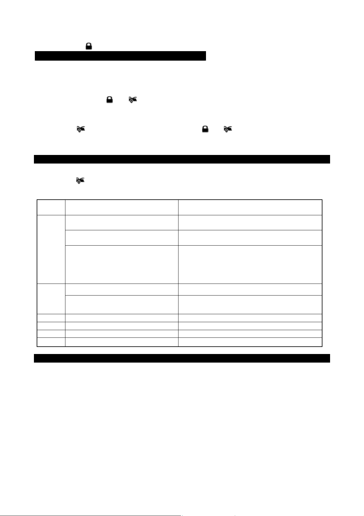
Exit: Press the button on the transmitter. A 3 long chirps & 3 parking light flashes to confirm exit.
RETURN TO FACTORY DEFAULT SETTING:
1. Turn the ignition ON then OFF 3 TIMES and stay in OFF position.
2. Push the Valet switch 12 times and holding in on the 12
hearing then release the valet switch. You are now in the “Return To Factory Default Setting”
programming mode.
ALA RM FEATURE ALL RETURNS TO FACTORY DEFAULT SETTING:
3. Press and hold the
confirmation six chirp with 3 long chirp to confir m the system “Alarm Feature I & II & III Program m ing all
returns to factory default setting.
START FEATURE ALL RETURNS TO FACTORY DEFAULT SETTING:
4. Press the
for 5 seconds, there will be a confirmation six chirp with 3 long chirp to confirm the s ystem “Star t F eature
I & II Programming all returns to factory default setting.
first, within 3 seconds press and hold the and buttons on the transmitter together
and buttons on the transmitter together for 5 seconds, there will be a
th
push until six chirps with a long chirp is
SHUTDOWN DIAGNOSTICS
The unit has the ability to report the cause of the last shutdown of the remote start system.
1. Turn the Ignition 'switch to ‘ON position.
2. Press the
3. The LED will now report the last system shutdown by flashing for 3 cycles in the following grouped
patterns:
LED
Flashes
1 (-) Safety Shutdown input (Hood)or 1. Close the hood.
2 (+) Safety Shutdown input (Brake)
Neutral Safety Switch input fail 3. Move the Enable Toggle Switch to “ON”
3
button on the transmitter.
Shutdown Mode
or Hand Brake (if installed) or
No RPM (Engine Checking TACH.)or Check H7/8 White/Red wire connection
2. Check H7/5 White/ Black wire connection.
1. Set the Hand Brake (if installed)
2. Check H7/7 White/ Violet wire connection.
position. (If installed.)
4. Move the gear selector to “Park”/ “NEUTRAL”
position.
5. Check H7/6 Black/White wire connection.
Low Voltage. (Engine Checking
Voltage.
5
6 System timed out
7 Transmitter
8 Tach. Signal has not been learned
Over-rev
Program the “Check Level” from
“Hi Check Level” to “Low Check Level”
Re-learning the RPM (Start Feature
II – 2 / 3
)
TESTING YOUR INSTALLATION:
Caution!! The follow procedure mus t be perform ed af ter the installation of the Remote Start Device. It is the
responsibility of the installing technician to complete these tests. Failure to test the unit in the following
manner may result in personal injury, property damage, or both.
1. Test the BRAKE shutdown circuit: With the vehicle in park (P), start the vehicle using the remote
transmitter, Once the engine is r unning, pr ess the br ak e pedal. T he vehicle should s hut down imm ediately.
If the vehicle continues to run, check the brake circuit WHITE/ VIOLET
2. Test the HOOD PIN shutdown circ uit: Start the vehicle using the remote trans mitter, Once the engine is
running, pull the hood release and raise the hood. The vehicle should shut down imm ediately. If the vehicle
continues to run, check the hood pin WHITE/ BLACK wire (H7/5) connection.
3. NEUTRAL START SAFETY TEST:
1. Set the vehicle parking brake.
2. Block the drive wheels to prevent vehicle movement.
3. Sitting in the vehicle, turn the ignition switch to “ON” or “RUN” position. But do not start the engine.
4. Step on the brake pedal and shift the gear selector into “DRIVE” (D).
5. Put your foot over the brake pedal but do not press down on it. Be ready to step on the brake to shut
down the Remote Start Device.
wire (H7/7) connection.
16
Page 17
6. Start the vehicle using remote transmitter.
a. If the starter does not engage, the test is complete.
b. If the starter engages, immediately step on the brake pedal to shut down the system, r echeck your
VIOLET wire (H1/1 starter output wire) connec tion. T he heavy gauge VIOLET wire must be connected
to the ignition switch side of the Neutral Start Switch. If the vehicle you are working on does not have
an Electrical Neutral Safety Switch, it will be necessary to reconfigure the Remote Starts W iring to
accommodate this vehic le. T he information concerning the Mechanic al Neutr al Saf ety Switch provided
below will help you to determine if the vehicle you are working on has this type of safety switch and will
provide alternate wiring methods to accommodate this situation.
MECHANICAL NEUTRAL SAFETY SWITCH CONSIDERATIONS:
Mechanical neutral safety switch configurations diff er slightly in that they do not offer the sam e level of saf ety
when installing a remote start device. Often when the ignition switch is turned off while the gear selector is in
any position other than park or neutral, the mechanic al func tion will not allow the k ey to be turned to the star t
position or be removed fr om the ignition c ylinder. This conf iguration prevents m echanical operation while the
vehicle is in gear but offers no cons ideration for electrical operation. Because of this potential problem, this
installation requires the additional connection of a safety wire from the remote start device to the vehicle
PARK/NEUTRAL ECM input or the vehicle key in sensor. This connection will prevent rem ote start operation
if the key is left in the ignition switch regardless of the gear selector position.
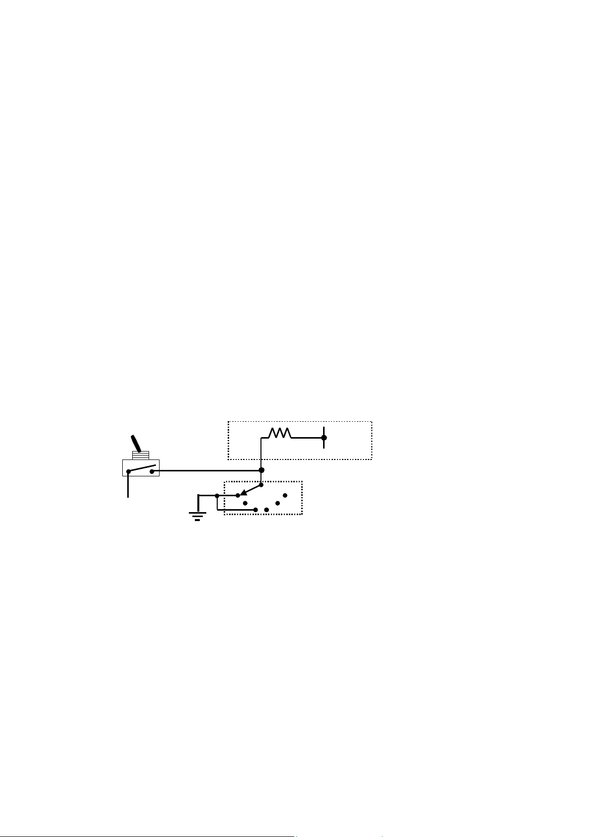
PARK/NEUTRAL ECM INPUT:
The Park/Neutral ECM input is the preferred method of installation. This not only maintains the integrity of the
factory circuit, it is also the easiest to install, providing the vehicle you are working on has this ECM input.
The installation required for this application (shown below), indicates in the slight reconfiguration of the
control switch wiring. Shown is a typical GM Park/Neutral ECM input circuit. To connect the Remote Start unit
to the GM Park/Neutral ECM input:
1. Locate the Orange/Black reference wire in the “C2” connector found at the ECM in GM B Body vehicles
or, locate the equivalent reference wire in the vehicle you are installing the Remote Start Unit in.
2. Connect the BLACK/WHITE Neutral Safety Switch wire (H7/6) to this reference wire.
NOTE: If the optional remote starts enable toggle switch is installed, connect the one side the enable switch
to this reference wire and connect the other side of the enable switch to the BLACK/WHITE Neutral Safety
Switch wire (H7/6) of the Remote Start unit.
The reference diagram below shows a typical GM B Body ECM reference wire and how it is to be connected
to the Remote Start Unit.
Optional Enable Switch
Ignition
Electronic Control Module (ECM)
Solid State, Do Not Measure
Resistance
P 1
To Neutral Safety
Switch Input wire
Black/White (H7/6
R
)
2
DN
KEY IN SENSOR CIRCUITS:
If the vehicle you are working on does not have or you cannot locate the ECM reference wire, there are two
alternatives available. Although not preferred, the vehicle Key In Sensor may be reconfigured to allow a
margin of safety and will prevent the vehicle with a Mechanical Neutral Start Switch from starting in gear.
WE ADVISES THAT YOU MAINTAIN THE FACTORY CIRCUIT WHENEVER POSSIBLE. The following two
circuits may be used only if the above circuit is not available.
NOTE: When completing an installation using either of the following key in sensor circuits, if the operator
inserts the ignition key while the vehicle is running under the control of the Remote Start, the vehicle will shut
down. This must be explained to the operator as it is in contrast to the normal operation of a vehicle utilizing
an electrical neutral start switch and is inconsistent with the operators manual.
Additional information concerning Key in Sensor methods 1&2 are listed below and should be reviewed
before considering either alternative.
Method 1 will allow the safety required for the remote start unit and prevent the vehicle from starting while in
any gear other than Park or Neutral while the key is in the ignition cylinder however, if the key is left in the
ignition switch and the door is left opened, the added relay will be energized causing a 150mA drain on the
battery.
Method 2 will allow the safety required for the remote start unit and prevent the vehicle from starting while in
any gear other than Park or Neutral while the key is in the ignition cylinder however, the original factory key in
chime module will not alert the owner that the key has been left in the ignition switch. In addition, this may
also effect other warning tones such as the light on reminder.
These situations should be carefully considered before altering the vehicle’s wiring and must be fully
17
Page 18
explained to the consumer.
This device complies with part 15 of the FCC rules. Operation is subject to the following two
conditions.
1)This device may not cause harmful interference, and
2)This device must accept any interference received, including interference that may cause undesired
operation.
Per FCC 15.21, you are cautioned that changes or modifications not expressly approved by the part
responsible for compliance could void the user’s authority to operate the equipment.
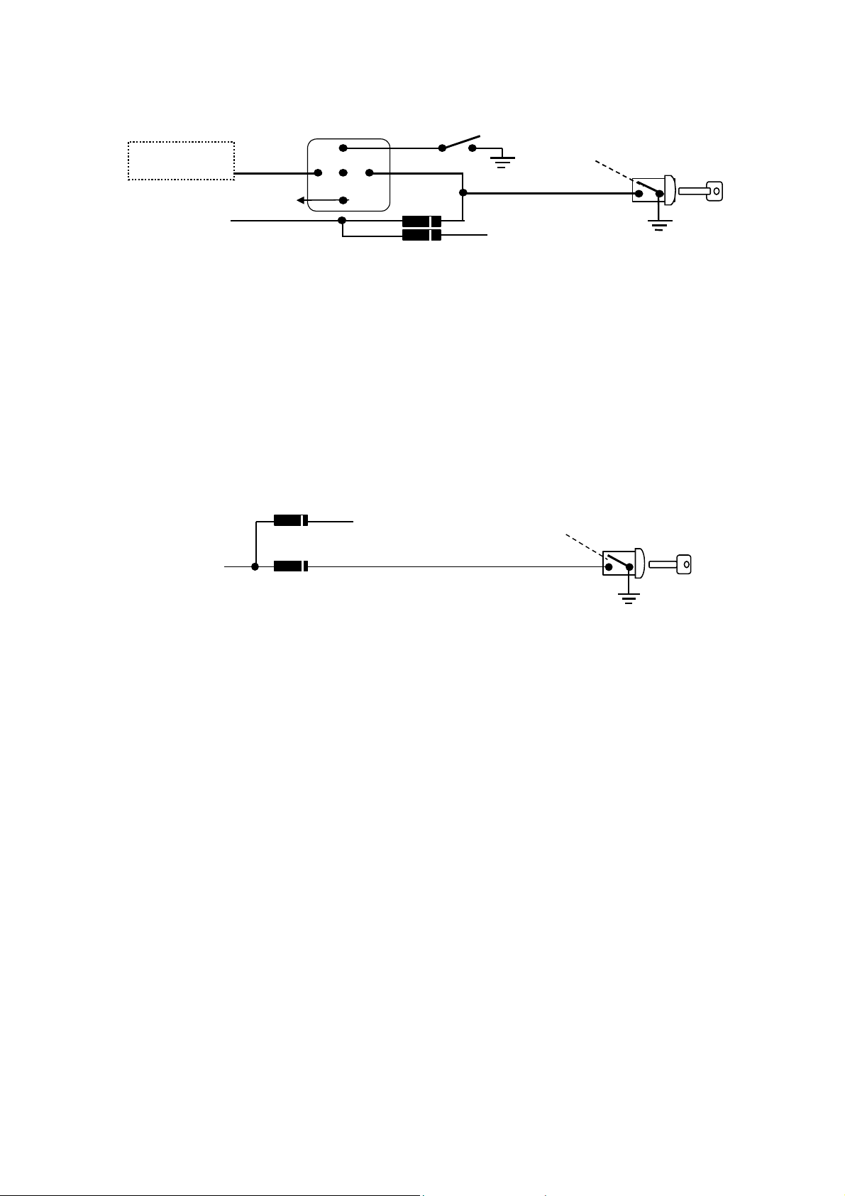
METHOD 1
Key In
Chime Module
Connected to (-) Negative
Safety Input Wire
White/ Black (H7/5
)
+ 12V
85
+ 12 V
87a
86
Drivers Door Pin Sw itch
30 87
1N4003
To Hood Pin Swit ch
Safety Shut Down (
To connect to the key in sensor as shown in method 1:
A. Locate the control wire that connects the drivers door pin switch to the key in sensor switch.
B. Cut this wire and connect the ignition cylinder side to chassis ground.
C. Locate the key in sensor switch wire that connects the chime module to the ignition cylinder.
D. Cut this wire and connect the ignition cylinder side to terminal 30 of a P&B VF45F11 or equivalent relay.
E. Connect the cathode (striped) side of a 4003 series diode to this same wire, and connect the (non striped)
side to the negative safely input wire (WHITE/ BLACK) (H7/5) of the Remote Start Unit.
F. Connect terminal 86 of the relay to a fused + 12 volt constant battery source.
G. Connect terminal 87 of the relay to the Chime Module side of the previously cut wire in step D.
H. Connect terminal 85 of the relay to the Drivers Door side of the pin switch wire previously cut in step B.
Note: A second 4003 series diode may be required to maintain the integrity of the hood open, shut down
circuit. If this is the case, it must be installed as shown in the diagram above. The anode (Non Stripped)
side must be connected to the WHITE/ BLACK wire (H7/5) of the Remote Start Unit. The cathode (Striped)
side must be connected to the hood pin switch.
Ignition Key In Sensor
Switch Closes with Key In
Ignition Cylinder
)
H7/5
METHOD 2
Connected to (-) Negative
Safety Input Wi re
White/ Black (H7/5
)
1N4003
To Hood Pin Swit ch
Safety Shut Down
(
)
H7/5
To connect to the key in sensor circuit as shown for method 2:
A. Locate the control wire that connects the drivers door pin switch to the key in sensor switch.
B. Cut this wire and connect the ignition cylinder side to chassis ground.
C. Locate the key in sensor switch wire that connects the chime module to the ignition cylinder.
D. Cut this wire and connect the ignition cylinder side to the Remote Start Negative Safety Shut down wire
WHITE/ BLACK (H7/5), using a 4003 series diode as shown above.
Note: A second 4003 series diode may be required to maintain the integrity of the hood open, shut down
circuit. If this is the case, it must be installed as shown in the diagram above. The anode (Non Striped) side
must be connected to the WHITE/ BLACK wire (H7/5) of the Remote Start Unit. The cathode (Striped) side
must be connected to the hood pin switch.
AFTER THE CONNECTION OF THE NEUTRAL START SAFETY WIRE AS INDICATED IN ANY OF THE
PREVIUOS ALTERNATE CONFIGURATINS, THIS CIRCUIT MUST BE TESTED FOR OPERATION.
Retest by following the steps outlined in the NEUTRAL START SAFETY TEST shown in this manual. (D)
Ignition Key In Sensor
Switch Closes with Key
In Ignition Cylinder
18
 Loading...