


SDR Modular Repeater
USER MANUAL
Version 0.4
3116 West Vanowen St.
Burbank, CA 91505
Tel: 818-840-8131
Fax: 818-840-8138
www.adrftech.com

SDR Repeater
User Manual V0.4
Glossary
The following is a list of abbreviations and terms used throughout this document.
Abbreviation/Term |
Definition |
|
AGC |
Automatic Gain Control |
|
ALC |
Automatic Level Control |
|
AROMS |
ADRF’ Repeater Operation and Management |
|
|
System |
|
BTS |
Base Transceiver Station |
|
CDMA |
Code Division Multiple Access |
|
CFE |
Compact Front End |
|
CW |
Continuous Wave (un-modulated signal) |
|
DAS |
Distributed Antenna System |
|
DL |
Downlink |
|
Downlink |
The path covered from the Base Transceiver |
|
|
Station (BTS) to the subscribers service area via |
|
|
the repeater |
|
HPA |
High Power Amplifier |
|
HW |
Hardware |
|
IF |
Intermediate Frequency |
|
LNA |
Low Noise Amplifier |
|
LTE |
Long Term Evolution |
|
MS |
Mobile Station |
|
PLL |
Phased Locked Loop |
|
PS |
Power Supply |
|
RF |
Radio Frequency |
|
SQE |
Signal Quality Estimate |
|
SW |
Software |
|
UL |
Uplink |
|
Uplink |
The path covered from the subscribers service |
|
|
area to the Base Transceiver Station(BTS) via the |
|
|
repeater |
|
VSWR |
Voltage Standing Wave Ratio |
|
Page | 2

SDR Repeater
User Manual V0.4
Released version: 0.4
Information in this document is subject to change without notice.
Advanced RF Technologies, Inc. 1996-2011.
All rights reserved.
Please send comments to:
E-Mail: |
info@adrftech.com |
Phone: |
(818) 840-8131 |
|
(800) 313-9345 |
Fax: |
(818) 840-8138 |
Address: |
Advanced RF Technologies, Inc. |
|
Attention: Technical Publications Department |
|
3116 Vanowen St. |
|
Burbank, CA 91505 |
|
USA |
|
www.adrftech.com |
Revision History |
|
|
|
|
Version |
|
Author |
Description |
Date |
0.1 |
|
Sun Kim |
Initial Release |
January 18, 2011 |
0.2 |
|
Sun Kim |
Revised max gain levels for SMR module |
May 10, 2011 |
0.3 |
|
Sun Kim |
Revised Band Selection section on the Install Page |
July 15, 2011 |
0.4 |
|
Sun Kim |
Update illustrations and changes to specifications; |
July 19, 2011 |
|
|
|
added Closeout Package, User Log, and Backup |
|
|
|
|
sections |
|
|
|
|
|
|
|
|
|
|
|
|
|
|
|
|
|
|
|
|
|
|
|
|
|
|
|
|
|
|
|
|
|
|
|
|
|
|
|
|
|
Page | 3

|
SDR Repeater |
|
User Manual V0.4 |
TABLE OF CONTENTS |
|
1. SDR REPEATER.............................................................................................................. |
6 |
1.1 Introduction.................................................................................................................. |
6 |
1.1.1 Highlights ............................................................................................................. |
6 |
1.1.2 Parts List ............................................................................................................... |
7 |
1.1.3 Repeater Quick View ............................................................................................ |
1 |
2. WARNINGS AND HAZARDS ........................................................................................ |
9 |
3. SDR OVERVIEW........................................................................................................... |
11 |
3.1 Switches & Fault Indicators....................................................................................... |
11 |
3.1.1 NMS and Module LED....................................................................................... |
11 |
3.1.2 Module LEDs...................................................................................................... |
11 |
3.1.3 Message Board Alarms and Notification............................................................ |
12 |
3.2 Switches and Ports ..................................................................................................... |
13 |
3.2.1 Power Switch...................................................................................................... |
13 |
3.2.2 Back Up Battery Switch & Battery Port............................................................. |
13 |
3.2.3 Ethernet Port and Host/Remote Switch .............................................................. |
14 |
3.2.4 RF Ports .............................................................................................................. |
14 |
3.5 Installation.................................................................................................................. |
15 |
3.5.1 Wall Mount Procedure ........................................................................................ |
15 |
3.5.2 Rack Mount Procedure ....................................................................................... |
15 |
3.5.3 Grounding ........................................................................................................... |
1 |
3.5.4 Antenna Separation/Isolation.............................................................................. |
17 |
3.5.5 Line of Sight ....................................................................................................... |
18 |
4. SDR WEB-GUI SETUP ................................................................................................. |
19 |
4.1 Repeater/PC Connection Using Web-GUI................................................................. |
19 |
4.2 Status Tab ................................................................................................................... |
20 |
4.2.1 StatusNMS........................................................................................................ |
20 |
4.2.2 StatusSMR, PCS, BRS ..................................................................................... |
22 |
4.3 Control Tab................................................................................................................. |
25 |
4.3.1 ControlNMS ..................................................................................................... |
25 |
4.3.2 ControlSMR, PCS, BRS................................................................................... |
26 |
4.4 Install Tab................................................................................................................... |
29 |
4.4.1 InstallNMS ....................................................................................................... |
29 |
4.4.2 InstallSMR........................................................................................................ |
31 |
4.4.3 InstallPCS......................................................................................................... |
33 |
4.4.4 InstallBRS ........................................................................................................ |
35 |
4.5 System........................................................................................................................ |
36 |
4.5.1 SystemAccount................................................................................................. |
37 |
4.5.2 SystemCloseout Package.................................................................................. |
38 |
4.5.3 SystemUser Log ............................................................................................... |
39 |
4.5.4 System: Update................................................................................................... |
39 |
4.5.5 SystemBackup .................................................................................................. |
39 |
|
Page | 4 |

|
|
SDR Repeater |
|
|
User Manual V0.4 |
4.6 |
Help............................................................................................................................ |
40 |
4.7 |
Logout ........................................................................................................................ |
40 |
Clicking the Logout button will log the current user off the system. .............................. |
40 |
|
5. MAINTENANCE GUIDE FOR SDR REPEATER .................................................... |
41 |
|
5.1 |
Periodic Inspection Checklist..................................................................................... |
41 |
5.2 |
Preventive Measures for Optimal Operation.............................................................. |
41 |
5.2.1 Recommendations............................................................................................... |
41 |
|
5.2.2 Precautions.......................................................................................................... |
41 |
|
6. WARRANTY AND REPAIR POLICY......................................................................... |
42 |
|
6.1 |
General Warranty ....................................................................................................... |
42 |
6.2 |
Limitations of Warranty ............................................................................................. |
42 |
6.3 |
Limitation of Damages............................................................................................... |
42 |
6.4 |
No Consequential Damages ....................................................................................... |
42 |
6.5 Additional Limitation on Warranty ............................................................................ |
42 |
|
6.6 |
Return Material Authorization (RMA)....................................................................... |
42 |
7. SPECIFICATIONS ........................................................................................................ |
43 |
|
7.1 |
Electrical Specifications............................................................................................. |
43 |
7.2 |
Mechanical Specifications ......................................................................................... |
43 |
7.3 |
Power Specifications.................................................................................................. |
44 |
7.4 |
Environment Specifications ....................................................................................... |
44 |
7.5 Warranty & Certificates ............................................................................................. |
44 |
|
APPENDIX A: MECHANICAL DRAWING................................................................... |
46 |
|
APPENDIX B: SHUTDOWN RETRY LOGIC............................................................... |
47 |
|
Page | 5

SDR Repeater
User Manual V0.4
1. SDR Repeater
1.1 Introduction
Four technologies in one body: SDR is an over-the-air repeater system that can incorporate up to four (4) technologies in one body. Current supported technologies are SMR800, SMR900, PCS, and BRS.
1.1.1 Highlights
• Supports up to 4 frequency bands simultaneously
oCovers the SMR800, SMR900, PCS, and BRS, LTE, Cellular, AWS bands
[SDR-S]SMR800- Covers 18 MHz
SMR900Covers 5 MHz
[SDR-P]PCS- Covers 65 MHz
3 independent RF PCS channels, each channel supports 1.25 to 18.75 MHz bandwidth
[SDR-B] BRSCovers 30 MHz
[SDR-700]LTE- Covers A+B:12MHz , C:11MHz
[SDR-C]Cellular- Covers 25MHz
[SDR-A] AWSCover 45MHz
•Composite Output Power of 24 or 30 dBm
•30 dB AGC Range @ 0.5 dB Step
•Adjustable AGC Output Power Level
•Adjustable ALC Level
•Band Selectable via Web-GUI
•Can Support up to 3 Non-Contiguous Bands on the PCS module
•Supports Network Management Monitoring System via SNMP
•Adjustable FA (3 channels)
•Digital filtering
•Incremental Automatic Shutdown/Resumption Time: SDR gradually increases the time span between automatic shutdown and resumption before it permanently shuts itself down
•Versatility and Usability: SDR gives total control to the user. Most of the control parameters, e.g., gain, output power, alarm threshold, etc. can be changed using the Web-GUI so that the user can adjust the system perfectly to the given RF environment
•Web-GUI connectivity via DHCP
•Supports DHCP; No 3rd party GUI software required
•Automated installation
Page | 6
|
|
|
SDR Repeater |
|
|
|
User Manual V0.4 |
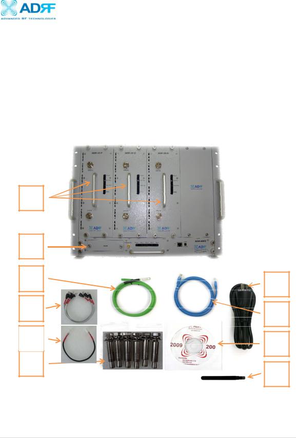
1.1.2 Parts List |
|
|
|
|
|
|
|
|
Label |
Quantity |
Description |
|
A |
1 |
SDR Network Management System (NMS) |
|
B |
Up to 3* |
Optional SDR Modules* |
|
C |
1 |
AC Power Cable |
|
D |
1 |
Ethernet Cable (Crossover) |
|
E |
1 |
Documentation CD** |
|
F |
1 |
Ground Cable |
|
G |
3 |
Channel Data Cable |
|
H |
1 |
Dipole Antenna |
|
I |
1 |
NMS Power Cable |
|
J |
6 |
Anchor Bolt |
Table 1 – Parts List
B |
|
A |
|
F |
C |
G |
D |
I |
E |
J |
H |
|
*At least 1 module must be present in order to use SDR
**CD includes: User Manual, Quick-Start Guide, and Troubleshooting Guide
Figure A – SDR Repeater Parts List
Page | 7

1.1.3 Repeater Quick View
LED indicator
Host / Remote
Switch & RJ-45 port
NMS Power Input
Port
NMS RJ-45 Hub
DC out for external modem box
SDR Repeater
User Manual V0.4
19” Rack  mount holes
NMS Output
 Power Port
RJ-45 Module
Communication Port
Battery Backup
Port
Module Power
Switch & AC IN port
Master AC IN
Module AC Power
Cords
Page | 8

SDR Repeater
User Manual V0.4
2. Warnings and Hazards
WARNING! ELECTRIC SHOCK
Opening the SDR could result in electric shock and may cause severe injury.
WARNING! EXPOSURE TO RF
Working with the repeater while in operation, may expose the technician to RF electromagnetic fields that exceed FCC rules for human exposure. Visit the FCC website at www.fcc.gov/oet/rfsafety to learn more about the effects of exposure to RF electromagnetic fields.
WARNING! DAMAGE TO REPEATER
Operating the SDR with antennas in very close proximity facing each other could lead to severe damage to the repeater.
RF EXPOSURE & ANTENNA PLACEMENT Guidelines
Actual separation distance is determined upon gain of antenna used.
Please maintain a minimum safe distance of at least 60 cm while operating near the donor and the server antennas. Also, the donor antenna needs to be mounted outdoors on a permanent structure.
Page | 9

SDR Repeater
User Manual V0.4
WARRANTY
Opening or tampering the SDR will void all warranties.
Lithium Battery: CAUTION. RISK OF EXPLOSION IF BATTERY IS REPLACED BY INCORRECT TYPE. DISPOSE OF USED BATTERIES ACCORDING TO INSTRUCTIONS.
Ethernet Instructions: This equipment is for indoor use only. All cabling should be limited to inside the building.
FCC Part 15 Class A
NOTE: This equipment has been tested and found to comply with the limits for a Class A digital device, pursuant to part 15 of the FCC Rules. These limits are designed to provide reasonable protection against harmful interference when the equipment is operated in a commercial environment. This equipment generates, uses, and can radiate radio frequency energy and, if not installed and used in accordance with the instruction manual, may cause harmful interference to radio communications. Operation of this equipment in a residential area is likely to cause harmful interference in which case the user will be required to correct the interference at their own expense.
CAUTION
Double Pole/Neutral Fusing.
Page | 10
SDR Repeater
User Manual V0.4
3. SDR Overview
3.1Switches & Fault Indicators
3.1.1NMS and Module LED
|
|
|
|
|
|
|
|
|
|
|
Figure 1: NMS LED |
|
|
|
|
|
|
|
|
|
|
SDR-NMS |
|
|
Specifications |
|
|
|
Power |
Solid Green |
|
NMS power is ON |
|
|
|
|
|
OFF |
|
NMS is powered OFF |
|
|
CH-1, CH-2, CH-3, |
Solid Green |
|
Module has communication with NMS |
|
|
|
CH-4 |
Solid Red |
|
Module has a communication failure with NMS |
|
|
|
|
|
OFF |
|
Module is powered OFF |
|
3.1.2 Module LEDs
SDR has LEDs on the front of the module as shown below in Figure 2.
|
|
Figure 1: Module LED |
SDR-Module |
|
Specifications |
Power |
Solid Green |
Module power is ON |
|
OFF |
Module is powered OFF |
Soft Fail |
Solid Yellow |
Soft Fail alarm exist in the system |
|
OFF |
No Soft Fail alarm are present in the system |
Hard Fail |
Solid Red |
Hard Fail alarm exist in the system |
|
OFF |
No Hard Fail alarms are present in the system |
RSSI |
Input < -85dBm |
Zero (0) bar On |
|
Input < -75dBm |
One (1) bar On |
|
Input < -65dBm |
Two (2) bars On |
|
Input < -55dBm |
Three (3) bars On |
|
Input < -45dBm |
Four (4) bars On |
|
Input >= -45dBm |
Five (5) bars On |
Page | 11

SDR Repeater
User Manual V0.4
3.1.3 Message Board Alarms and Notification
Parameters |
Remark |
Communication failure |
Internal Communication failure |
RMF |
Field replaceable module failure |
RESET |
Reset alarm |
Heartbeat |
Heartbeat |
OSC |
Oscillation detected |
UL RSSI fail |
Power at coverage port too high |
UL PLL fail |
UL Synthesizer failure |
H/W fail |
Hardware failure |
S/W fail |
Software failure |
UL Emission fail |
UL Out-of-band emissions out of spec |
DL RSSI fail |
Donor Power too high/low |
ISO fail |
Low isolation |
DL PLL fail |
DL Synthesizer failure |
DL Spur fail |
DL Spurious emissions out of spec |
Interfere |
Interferer power exceeded |
Link Fail |
Communication error between the module and NMS |
Over Temperature |
Module is above the normal operating temperature |
Under Temperature |
Module is below the normal operating temperature |
Fan Fail |
System has detected an issue with the fan |
System Halt |
System is in a shutdown state due to a hard fail alarm |
DL Signal not detected |
DL signal is below the specified level |
DL Signal Low |
DL signal is below the specified level |
Outband overload |
System has detected a strong out of band signal |
Input overload |
In-band incoming signal strength is above max input level |
Synthesizer Lock Fail |
Issue with internal system amp |
DSP Fault |
System has detected an issue with the internal DSP chip |
DL RF Power |
Input + gain does not match the output level (above delta of 6 dB) |
Overpower |
Output level is above the max output levels |
DL Oscillation Alarm |
Oscillation has been detected in the system |
VSWR |
Power is being reflected back to the repeater |
AC Fail |
Power supply is not operating within specs |
DC Fail |
Power supply is not operating within specs |
Over Current |
Power supply is not operating within specs |
Page | 12

SDR Repeater
User Manual V0.4
3.2Switches and Ports
3.2.1Power Switch
The AC Power on/off switch is located at the back of each individual module. Each module must be powered on separated. The switch should be powered on after the repeater has been installed properly.
Figure 2: SDR Repeater Power Switch View
3.2.2 Back Up Battery Switch & Battery Port
Figure 3: Battery Backup Port
The SDR module can be connected to an ADRF-BBU (ADRF Battery Backup) to provide power during a power failure. If an ADRF-BBU is utilized, connect the ADRF-BBU to the SDR via the external battery port as shown in Figure 4.
(WARNING: The circuit switch on the ADRF-BBU must be set to OFF before connecting the ADRF-BBU to the SDR to prevent damage to the repeater or the ADRF-BBU and personal injury.)
Note: Please contact ADRF Technical Support for assistance if you are unfamiliar with the installation procedure of our battery box.
Page | 13
SDR Repeater
User Manual V0.4
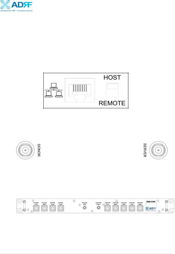
3.2.3 Ethernet Port and Host/Remote Switch
Ethernet Port
The Ethernet port can be used to communicate directly with the SDR using a RJ-45 crossover cable or can also be used to connect the SDR to an external modem box.
Host/Remote Switch
The Host/Remote Switch allows the user to switch the default Repeater IP, Subnet Mask, and Gateway of the repeater to an alternative setup. These settings can be adjusting by logging into the repeater in HOST mode and configuring the settings under the Modem Box Setting section on the Install Page (section 4.4). Once the settings are set, flipping the switch to the REMOTE position will reboot the repeater with the new alternate settings. Please note that when the repeater is set to the REMOTE position, DHCP is disabled and the repeater will not automatically assign an IP address to any device that connects directly to the repeater.
Figure 4: Ethernet Port and Host/Remote Switch
3.2.4 RF Ports
Module RF Ports
Donor and server antennas can be connected directly to the modules or the optional SDR-CHC (channel combiner) can be used to split or combine signals.
Figure 5: RFU RF port
Optional SDR-CHC
An optional channel combiner can be mounted directly above the SDR. The donor portion of the SDR-CHC can be used to split up a combine donor signal into PCS, BRS, and SMR. The server portion of the SDRCHC can be used to combine the server signals (PCS, BRS, 2.4 GHz WIFI, and SMR) into the Server Sum port. Please contact sales@adrftech.com if you are interested in purchasing the SDR-CHC.
Figure 6: Donor Combiner RF port
Page | 14
3.5Installation
3.5.1Wall Mount Procedure
Verify that the SDR and mounting hole are in good condition
Remove all SDR modules from the system
Place the SDR chassis up against the wall so that that module’s RF ports face the ceiling
Mount the SDR chassis to wall use the six (6) mounting hold on the wall mount bracket
Install the SDR modules into the chassis and secure the module by tightening the four (4) hand screws
Connect the power and data cables at the bottom on the SDR
Connect the GND cable
Connect the Antenna cable
Connect the Power cable
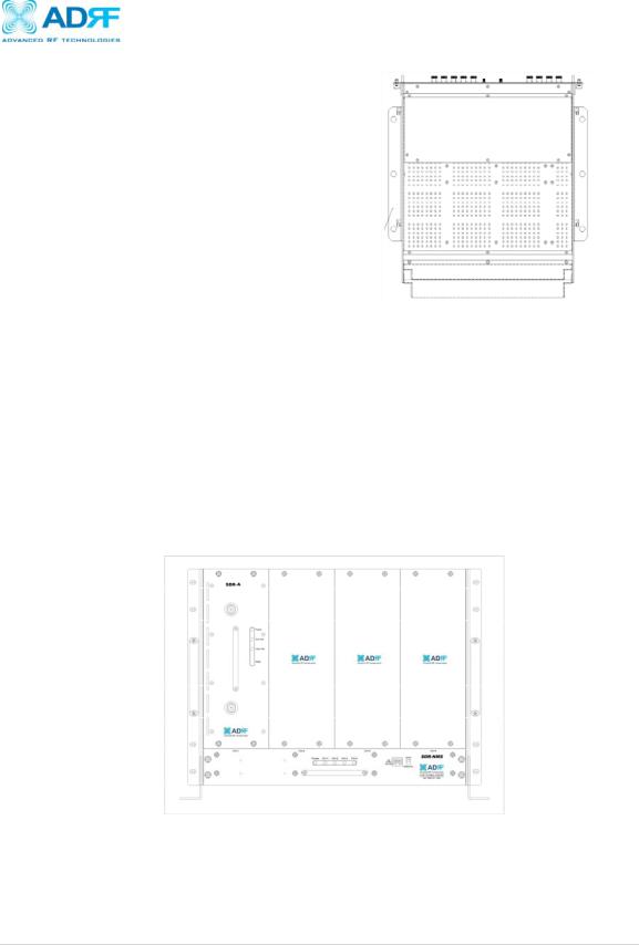
3.5.2 Rack Mount Procedure
SDR Repeater
User Manual V0.4
Wall Mount
Bracket
Figure 8: SDR Wall Mount
Verify that the SDR and mounting hole are in good condition
Remove all SDR modules from the system
Install the SDR chassis into the 19” rack mount system
Screw the SDR chassis into the 19” rack mount system using the eight (8) mounting holes
Install the SDR modules into the chassis and secure the module by tightening the four (4) hand screws
Connect the power and data cables at the back of the SDR
Connect the GND cable
Connect the Antenna cable
Connect the Power cable
Figure 7: SDR Rack Mount
Page | 15
 Loading...