

Page 1

User Manual V1.01
ACR330 Validator
with QR Code Scanner
Subject to change without prior notice info@acs.com.hk
www.acs.com.hk
Page 2

Page 2 of 57
Table of Contents
1.0. Introduction ............................................................................................................. 4
2.0. ACR330 Hardware Overview ................................................................................... 5
2.1. Parts of the Reader ................................................................................................................ 5
2.1.1. Connection Ports ........................................................................................................... 6
2.1.2. Input Power, RS232, RS485 Pin Assignment ............................................................... 7
2.1.3. SAM Slot Arrangement ................................................................................................. 8
2.1.4. LTE Board Description .................................................................................................. 9
2.2. ACR330 EVK Components.................................................................................................. 10
2.3. Installing the Back Mount ..................................................................................................... 11
2.3.1. Preparing the Components ......................................................................................... 11
2.3.2. Installing ACR330 using a Vertical Pole ..................................................................... 16
2.3.3. Installing the ACR330 using a Horizontal Pole ........................................................... 23
2.4. Turning the Device ON/OFF ................................................................................................ 30
2.4.1. Turn ON the Device .................................................................................................... 30
2.4.2. Turn OFF the Device................................................................................................... 30
2.5. Accessing the ACR330 through a PC using LAN ................................................................ 31
2.6. Replacing the Real Time Clock (RTC) Battery .................................................................... 34
3.0. ACR330 Software Overview .................................................................................. 36
3.1. C++ Software Block Diagram .............................................................................................. 36
3.2. Java Software Block Diagram.............................................................................................. 37
3.3. ACR330 Demo ..................................................................................................................... 38
3.3.1. Contactless Module..................................................................................................... 38
3.3.2. Connectivity Module .................................................................................................... 43
3.3.3. Barcode Module .......................................................................................................... 47
3.3.4. GPS Module ................................................................................................................ 50
3.3.5. Card Slot Module ........................................................................................................ 51
3.3.6. LED/Speaker Settings Module .................................................................................... 52
3.3.7. Settings Module .......................................................................................................... 54
3.3.8. Power OFF Module ..................................................................................................... 55
3.4. Installing an Application ....................................................................................................... 56
3.4.1. Changing the Application Directory (For FW1.7.10 and below) ................................. 57
List of Figures
Figure 1 : ACR330 Parts ....................................................................................................................... 5
Figure 2 : ACR330 Connection Ports ..................................................................................................... 6
Figure 3 : ACR330 Input Power ............................................................................................................. 7
Figure 4 : SAM Slot Arrangement .......................................................................................................... 8
Figure 5 : LTE Board Components ........................................................................................................ 9
Figure 6 : ACR330 EVK Components .................................................................................................. 10
Figure 7 : Pole Hole Position ................................................................................................................ 11
Figure 8 : Power Button ........................................................................................................................ 30
Figure 9 : Jumper Location................................................................................................................... 31
Figure 10 : RSR232 Debug Console Cable ......................................................................................... 31
Figure 11 : Ethernet Port ...................................................................................................................... 32
Figure 12 : RJ11 Serial Port ................................................................................................................. 33
Figure 13 : C++ Software Block Diagram ............................................................................................. 36
Figure 14 : Java Software Block Diagram ............................................................................................ 37
Figure 15 : ACR330 Demo Default Screen .......................................................................................... 38
Figure 16 : Contactless Module ........................................................................................................... 38
ACR330 Validator with QR Code Scanner – User Manual info@acs.com.hk
Version 1.01 www.acs.com.hk
Page 3

Page 3 of 57
Figure 17 : DESfire TOP-UP ................................................................................................................ 39
Figure 18 : DESfire PAY ....................................................................................................................... 40
Figure 19 : DESfire CHECK BALANCE ............................................................................................... 41
Figure 20 : EMV Contactless Card ....................................................................................................... 42
Figure 21 : Connectivity Module ........................................................................................................... 43
Figure 22 : Connection and APN Settings ........................................................................................... 44
Figure 23 : NTP Settings ...................................................................................................................... 45
Figure 24 : Wi-Fi Settings ..................................................................................................................... 46
Figure 25 : Bluetooth Settings .............................................................................................................. 47
Figure 26 : Barcode / QR code Validity Check..................................................................................... 48
Figure 27 : Barcode / QR code Information ......................................................................................... 49
Figure 28 : GPS Settings ...................................................................................................................... 50
Figure 29 : Card Slot Information ......................................................................................................... 51
Figure 30 : LED Settings ...................................................................................................................... 52
Figure 31 : Speaker Settings ................................................................................................................ 53
Figure 32 : Device Information ............................................................................................................. 54
Figure 33 : Additional Settings ............................................................................................................. 54
Figure 34 : Auto Power Settings .......................................................................................................... 54
Figure 35 : Power OFF Module ............................................................................................................ 55
List of Tables
Table 1 : ACR330 Parts Description ....................................................................................................... 5
Table 2 : ACR330 Connection Ports Description ................................................................................... 6
Table 3 : ACR330 Input Power Pins Description .................................................................................... 7
Table 4 : ACR330 LTE Board Description .............................................................................................. 9
Table 5 : Rubber Adapter According to Pole Size and Orientation ...................................................... 14
Table 6 : Hole Cover According to Pole Size and Orientation.............................................................. 15
ACR330 Validator with QR Code Scanner – User Manual info@acs.com.hk
Version 1.01 www.acs.com.hk
Page 4
Page 4 of 57
1.0. Introduction
The ACR330 Bus Validator is designed specifically for Automatic
Fare Collection (AFC) systems. It offers the convenience of
cashless payment in buses, ferries, trams, railways and other
transportation modes.
The bus validator enables high-speed transaction processing and
records collection through 13.56 MHz contactless (RFID)
technology, supporting ISO 14443 Type A and B cards,
MIFARE®, and FeliCa. Being certified with major payment
standards such as PBOC Level 1 (Contactless) and EMV™
Levels 1 and 2 (Contactless) including MasterCard® Contactless
and Visa PayWave® offers flexibility to adapt to an open loop
payment system. An embedded barcode scanner enables
transactions through the use of print or mobile barcodes.
It has advanced wireless connectivity options for data transfer such as GSM/GPRS, 3G/4G, and Wi-Fi.
With an optional GPS feature, it can also locate vehicles, manage fleets and set flexible distancebased fares. Protecting the bus validator from harsh environment is its IP54 rating for dust and water
protection and the additional Military Standard MIL-STD-810 for Shock and Vibration.
This document provides detailed guidelines on using the ACR330.
ACR330 Validator with QR Code Scanner – User Manual info@acs.com.hk
Version 1.01 www.acs.com.hk
Page 5
Page 5 of 57
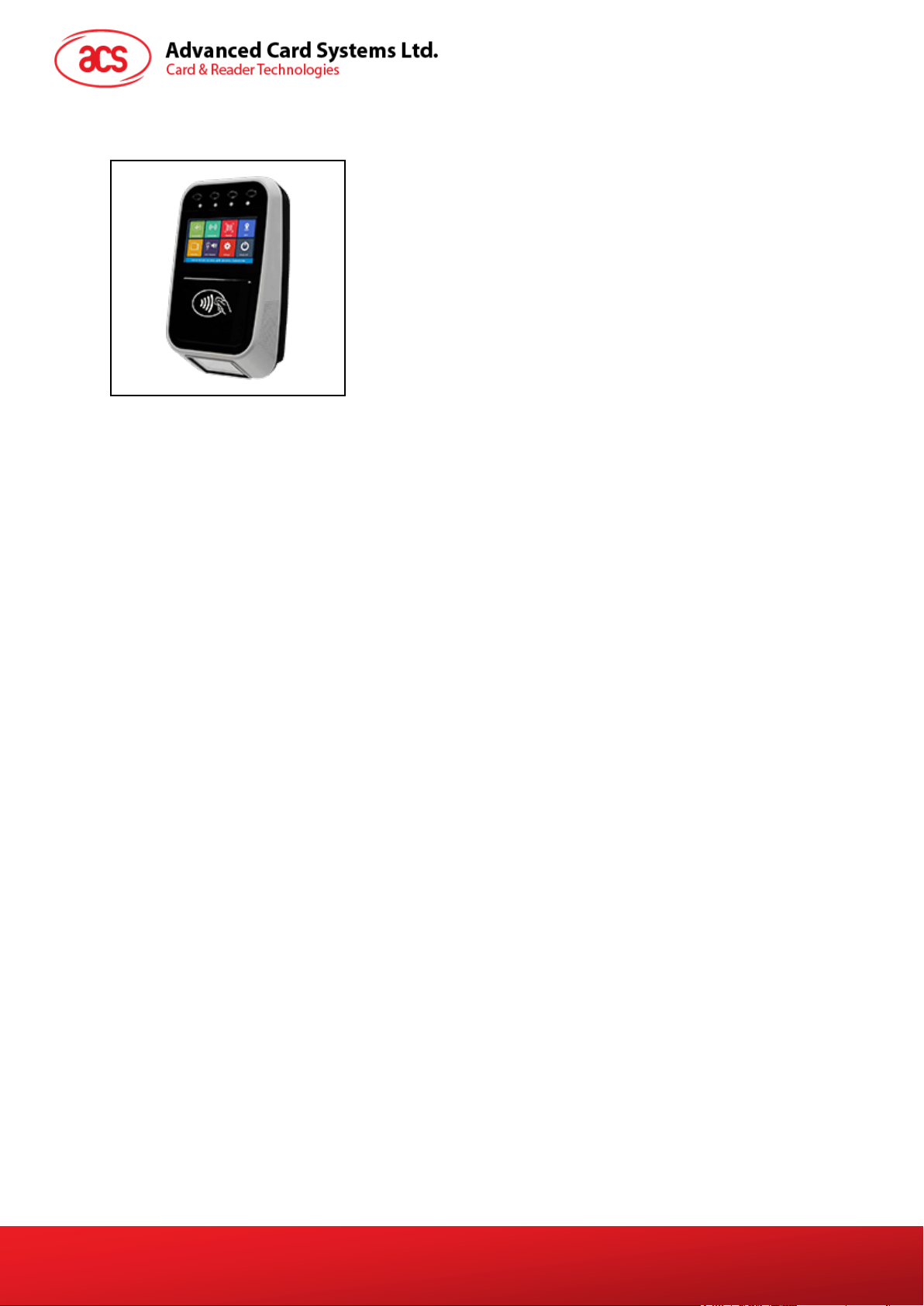
Part Number
Part Name
1a, 1b, 1c,1d
Programmable Button with Backlight (Blue)
2
Blue LED Indicator (For passenger)
3
Yellow LED Indicator (For passenger)
4
Green LED Indicator (For passenger)
5
Red LED Indicator (For passenger)
6
LCD Display with Touch Panel
7
Tapping Area
8
1D/2D Barcode Scanning Area
9
Speaker
10
Green LED Indicator (For Driver)
11
Red LED Indicator (For Driver)
12
Buzzer
13
Power Button
14
SIM and SD Card Cover
15
Back Cover
1a
1b
1c
1d
2 3 4
5 6 7
8
9
10
11
12
13
14
15
2.0. ACR330 Hardware Overview
2.1. Parts of the Reader
Figure 1: ACR330 Parts
ACR330 Validator with QR Code Scanner – User Manual info@acs.com.hk
Version 1.01 www.acs.com.hk
Table 1: ACR330 Parts Description
Page 6
Page 6 of 57
Port Number
Port Name
1
Power Socket
2
RJ11 Serial Port (RS232, RS485)
3
USB Host
4
Ethernet
5
USB Client (for internal debugging)
6
Socket for External GPS Antenna
7
SAM Cover with 4 ISO7816 SAM Socket
inside
1
2 3 4
5 6 7
2.1.1. Connection Ports
Figure 2: ACR330 Connection Ports
Table 2: ACR330 Connection Ports Description
ACR330 Validator with QR Code Scanner – User Manual info@acs.com.hk
Version 1.01 www.acs.com.hk
Page 7
Page 7 of 57
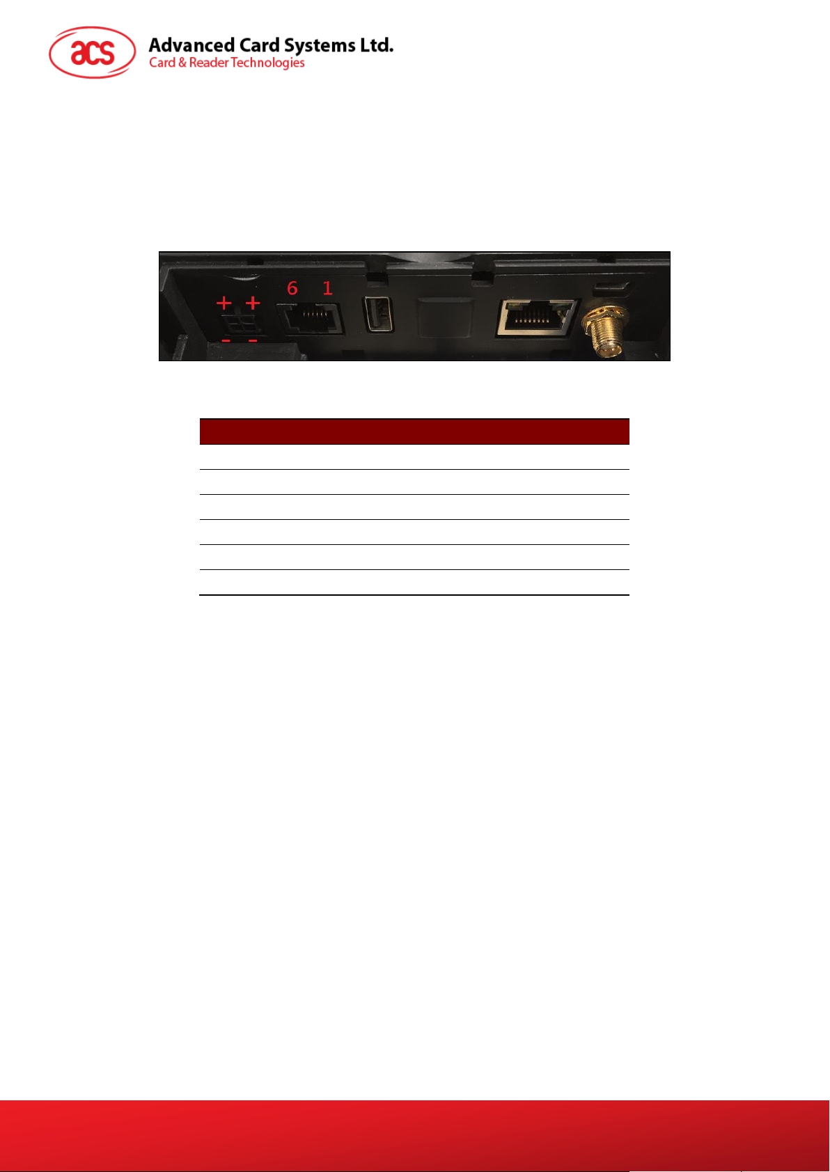
Pin Number
Pin Name
1
NC 2 RS232-TX
3
RS232-RX
4
RS485-A
5
RS485-B
6
GND
2.1.2. Input Power, RS232, RS485 Pin Assignment
Power Socket Type: Molex 43045-0400, Micro-Fit 3.0 Right Angle Header, 3.00mm Pitch, Dual Row,
4 Circuits
RS232, RS485 Socket type: RJ11
Pin Assignment is shown as below:
Figure 3: ACR330 Input Power
Table 3: ACR330 Input Power Pins Description
Note: Below is the application direct access device paths list:
RS232 - /dev/ttyO0 (115200 baud, 8 data bits, no parity, and 1 stop bit)
RS485 - /dev/ttyO1(115200 baud, 8 data bits, no parity, and 1 stop bit)
USB disk - /media/udiskp1
ACR330 Validator with QR Code Scanner – User Manual info@acs.com.hk
Version 1.01 www.acs.com.hk
Page 8
Page 8 of 57
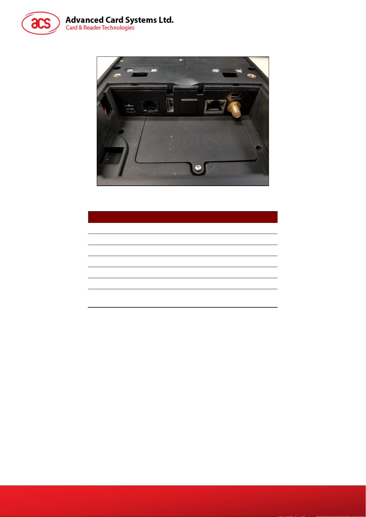
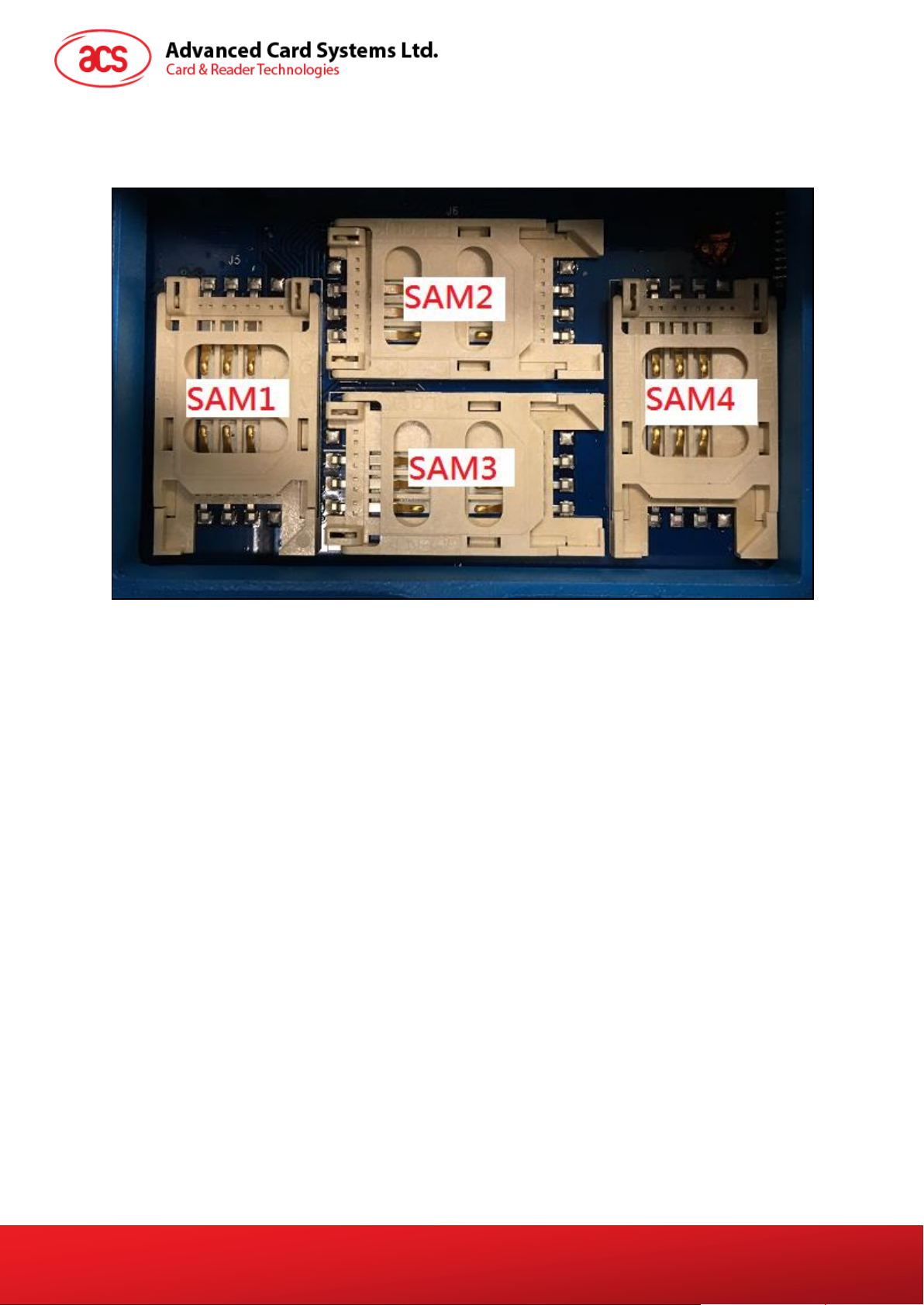
2.1.3. SAM Slot Arrangement
The SAM Slot Arrangement is shown in the image below.
Figure 4: SAM Slot Arrangement
ACR330 Validator with QR Code Scanner – User Manual info@acs.com.hk
Version 1.01 www.acs.com.hk
Page 9
Page 9 of 57
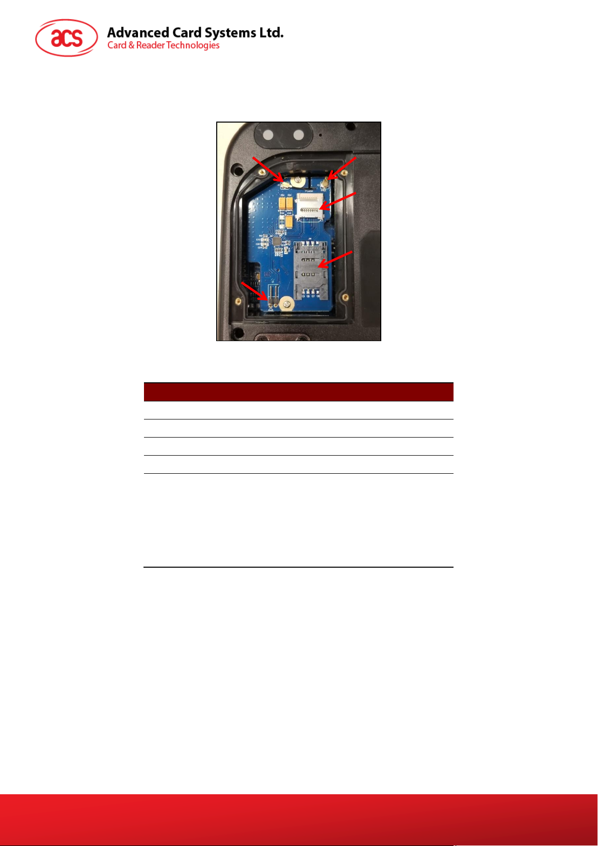
Part Number
Part Name
1
4G Antenna Socket
2
GPS Socket
3
SD Card Slot
4
SIM Card Slot
5
Console Jumper Port (Console mode is
enabled through RS232 when jumper is
plugged in.
Speed: 115200 baud, 8 data bits, no parity,
and 1 stop bit)
Note: Jumper is not included in standard
product. May be purchased locally.
4
5
1
2
3
2.1.4. LTE Board Description
Figure 5: LTE Board Components
Table 4: ACR330 LTE Board Description
Note: Below is the application direct access device paths list:
MicroSD - /media/sdcardp1
ACR330 Validator with QR Code Scanner – User Manual info@acs.com.hk
Version 1.01 www.acs.com.hk
Page 10
Page 10 of 57
1 2 3
4
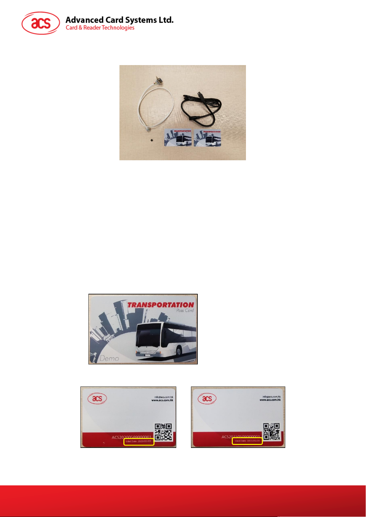
2.2. ACR330 EVK Components
Figure 6: ACR330 EVK Components
The ACR330 EVK contains the following items:
1. Debug Cable
2. Console Jumper Port
3. 1m DC Power Jack to Molex Power Cord
The cable should comply with the required power rating.
(example: 12V == 4A; 24V == 2A)
A DC jack adapter may be needed depending on the power supply used.
4. Demo Cards
Purpose: To be used for the demo pre-installed on the reader
2 pcs. Test Cards [Type: Mifare Desfire EV1]
There are QR Codes at the back of the cards to emulate both a valid and an expired
card.
Note: For more information about the demo, please check Section 3.3 - ACR330 Demo
ACR330 Validator with QR Code Scanner – User Manual info@acs.com.hk
Version 1.01 www.acs.com.hk
Page 11
Page 11 of 57
Cable out
2 Holes that
prevent the
back- mount
from moving
Cable in
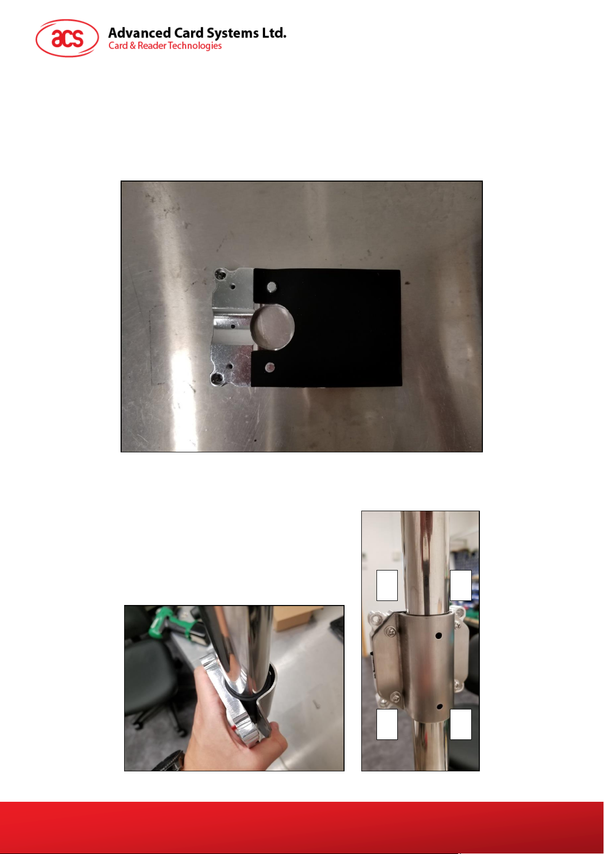
2.3. Installing the Back Mount
2.3.1. Preparing the Components
Prior to installation, it is necessary to ensure that the components are complete and in good condition.
Both the Pole and the Back Mount should be ready before the installation.
2.3.1.1. The Pole
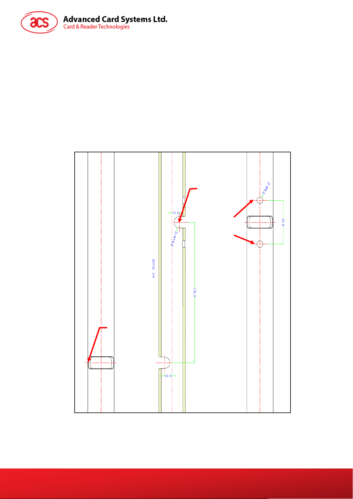
To prepare the pole:
1. On the right side of the pole, check if the holes needed to secure the position of the ACR330 have
been well-drilled. For reference, please refer to the illustration below.
Note: The position of the holes can be adjusted depending on the requirement
Figure 7: Pole Hole Position
ACR330 Validator with QR Code Scanner – User Manual info@acs.com.hk
Version 1.01 www.acs.com.hk
Page 12
Page 12 of 57
Key
Back-mount
Brown Box
2. Check if the required cables (e.g. power cords) have been properly passed through the poles, and
that they can reach the position of the mounting with ample extra length.
3. Check the following details of the pole:
Diameter (31/32mm or 35mm)
Orientation (Vertical or Horizontal)
4. After checking the pole, proceed to check the back -mount.
2.3.1.2. The Back-mount
To prepare the back mount:
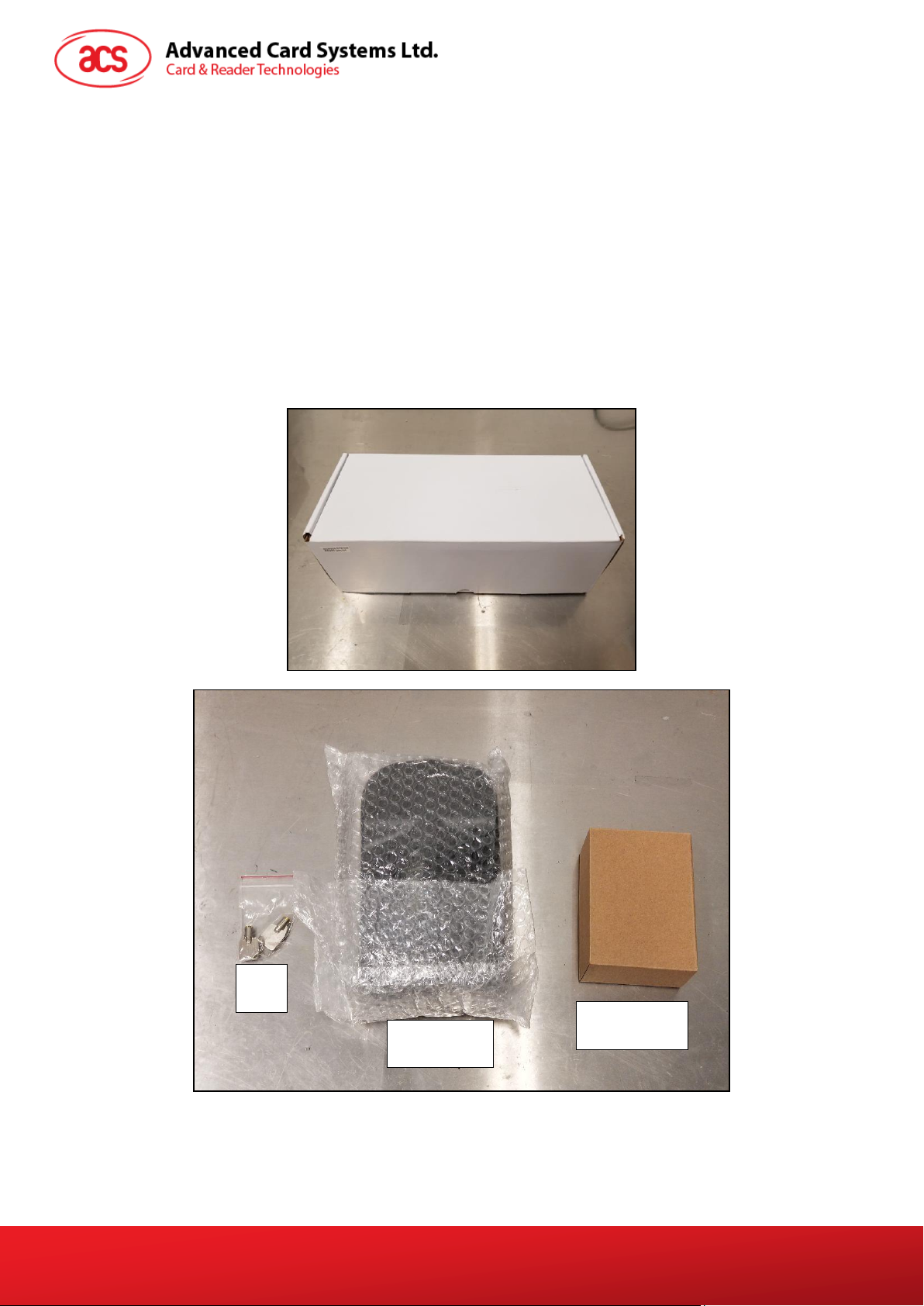
1. Unbox the tools. A back-mount, a key, and a brown box are included in the package.
ACR330 Validator with QR Code Scanner – User Manual info@acs.com.hk
Version 1.01 www.acs.com.hk
Page 13
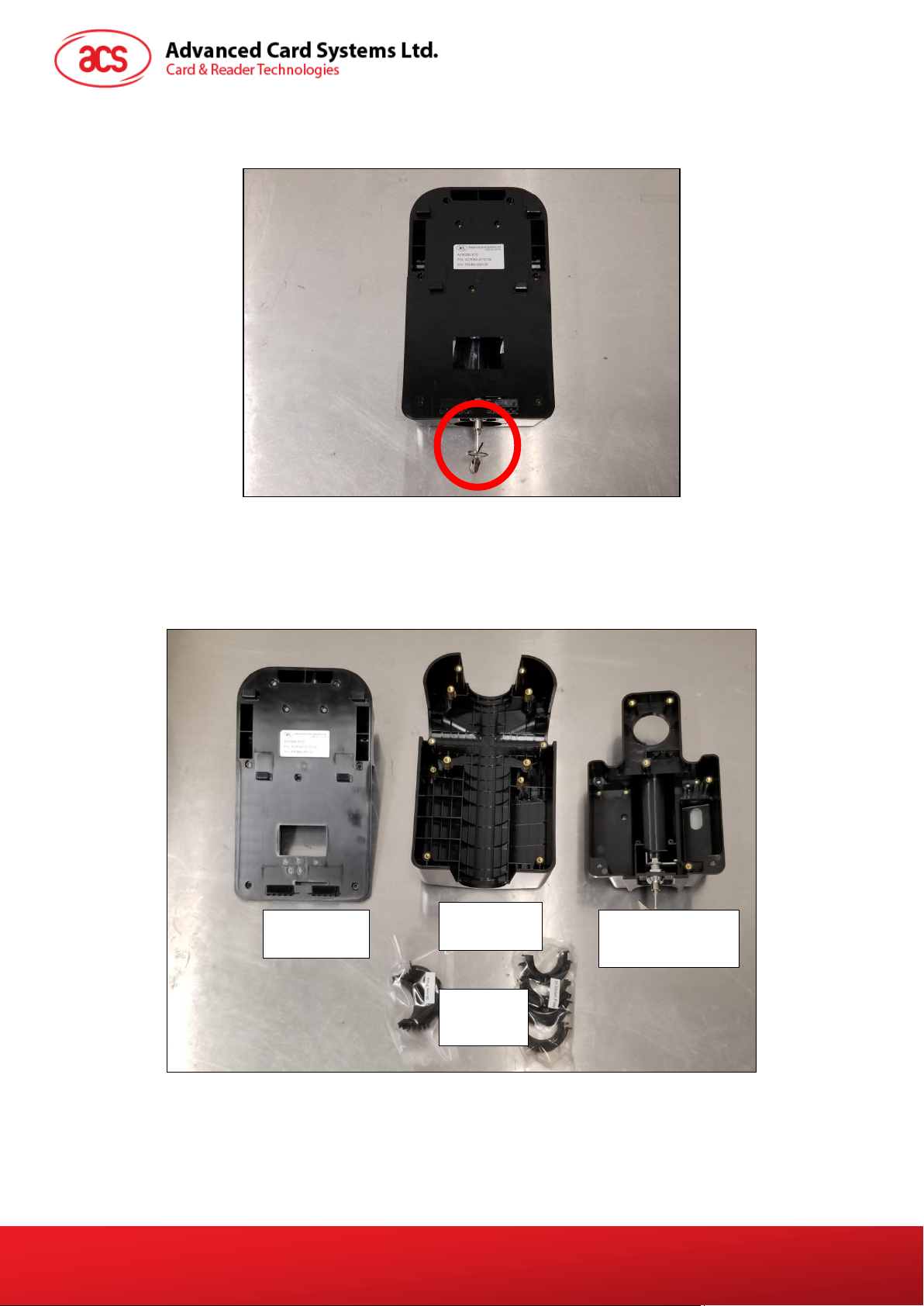
Page 13 of 57
Front Cover
Back Cover
Water-resistant
Part
Rubber
Adapters
2. Using the key, open the lock of the back-mount. The lock is located at the bottom part of the
back-mount as shown on the image below:
3. Unlocking the back-mount will cause it to disassemble into three parts: front cover, back
cover, and the water-resistant part. Rubber adapters are also included inside the backmount.
ACR330 Validator with QR Code Scanner – User Manual info@acs.com.hk
Version 1.01 www.acs.com.hk
Page 14
Page 14 of 57
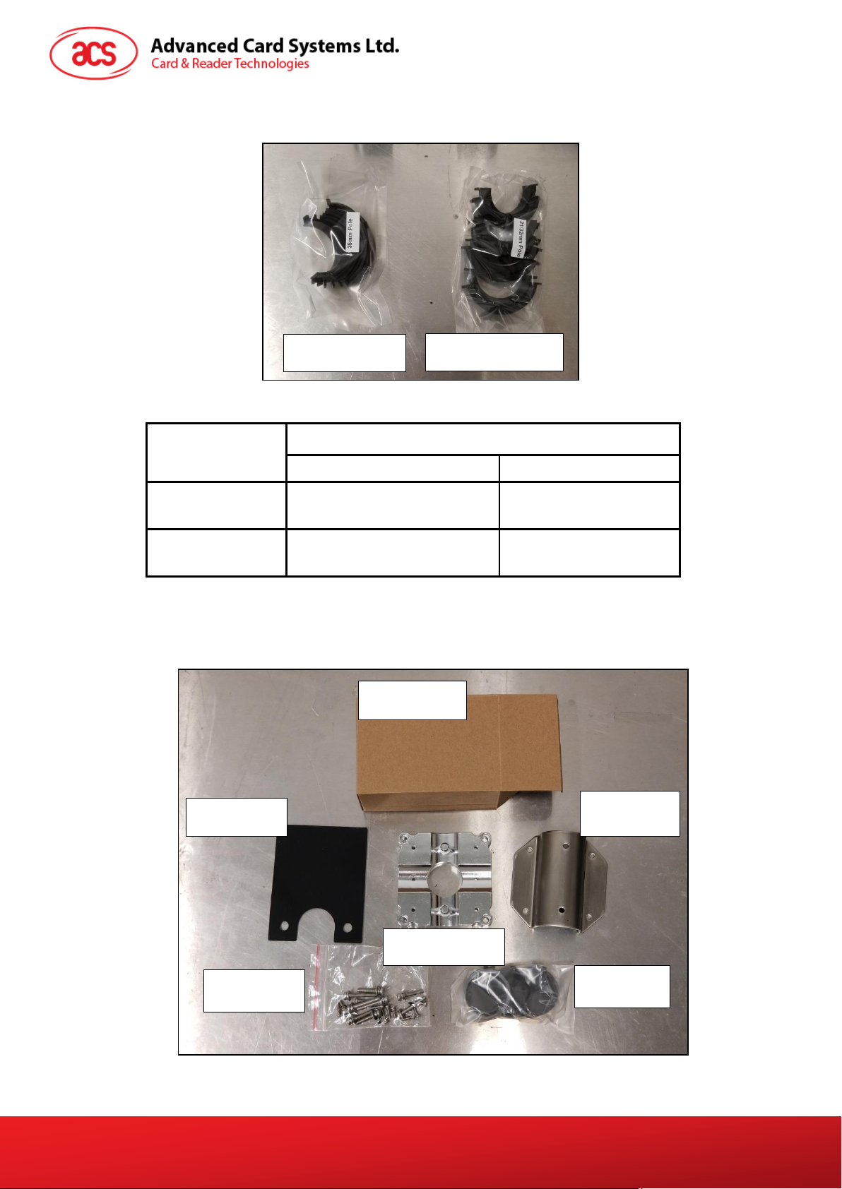
Orientation of pole
for mounting
Pole diameter
31/32mm
35mm
Horizontal (H)
HB-D31/32, HB-D31/32,
HT-D31/32, HT-D31/32,
HB-D35, HB-D35,
HT-D35, HT-D35,
Vertical (V)
VB-D31/32, VB-D31/32,
VT-D31/32, VT-D31/32,
VB-D35, VB-D35,
VT-D35, VT-D35,
For 31/32mm Pole
For 35mm Pole
Hole Cover
Screws
Rubber Part
Metal Part 1
Metal Part 2
Brown Box
4. Using the codes on their inner side, select the rubber adaptors that match the pole’s size
and orientation, as shown on the table below:
Table 5: Rubber Adapter According to Pole Size and Orientation
5. Open the brown box. The following components are inside the box.
ACR330 Validator with QR Code Scanner – User Manual info@acs.com.hk
Version 1.01 www.acs.com.hk
Page 15
Page 15 of 57
Orientation of pole
for mounting
Pole diameter
31/32mm
35mm
Horizontal
VT, VT
VT, VT
Vertical
HT, HT
HT, HT
HT
HT
VT
VT
VT for
Horizontal Pole
HT for Vertical Pole
6. Select the appropriate hole cover according to the orientation of the pole, as shown in the
photo and table below:
Table 6: Hole Cover According to Pole Size and Orientation
7. After preparing the back-mount, installation can now be started.
Version 1.01 www.acs.com.hk
ACR330 Validator with QR Code Scanner – User Manual info@acs.com.hk
Page 16
Page 16 of 57
1
2
3
4
2.3.2. Installing ACR330 using a Vertical Pole
Note: Please ensure that the components are well prepared before starting the installation.
To install the ACR330 using a vertical pole:
1. Place the rubber part on top of the metal part 1.
Note: This step is only applicable when using a 31/32mm pole. When using a 35mm pole,
please skip this step.
2. Put metal part 1 and metal part 2 on top of the pole and screw them together using PM4*20
screws (4 pieces). The order of screwing is shown on the picture below:
ACR330 Validator with QR Code Scanner – User Manual info@acs.com.hk
Version 1.01 www.acs.com.hk
Page 17
Page 17 of 57
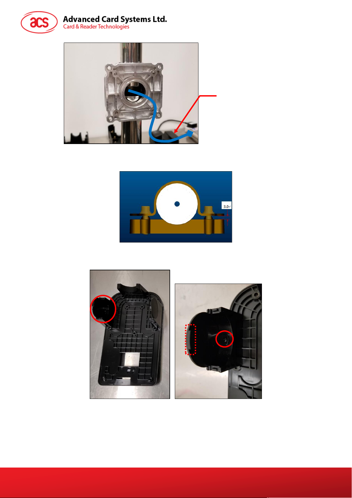
Note: This is where the Connection
Cable (ie, Power Cord) will go
through. Make sure that the cables
are out so that they may be easily
connected to the ACR330 Validator
later on.
HT
HT
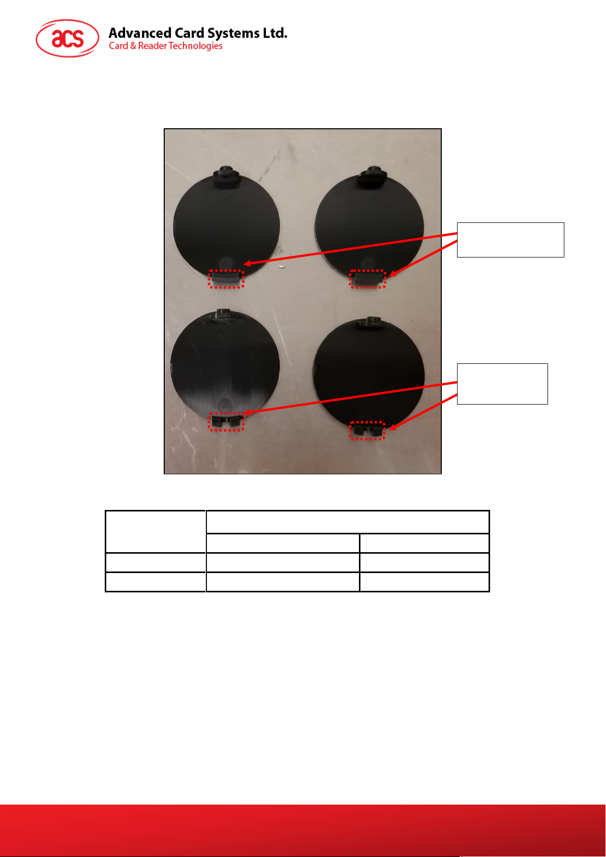
Note: The gap between the two metal parts is around 3mm for any size (31/32/35mm) of
pole.), as shown in the picture below.
3. Screw the rubber adapters and hole covers using the PB2.0 screws (2 pieces). The exact
position is shown on the photos below:
ACR330 Validator with QR Code Scanner – User Manual info@acs.com.hk
Version 1.01 www.acs.com.hk
Page 18

Page 18 of 57
HT
Hole Cover
HT
Hole Cover
HT
Hole Cover
HT
Hole Cover
VT-D31/32
Rubber Adapter
VT-D31/32
Rubber Adapter
VB-D31/32
Rubber Adapter
VB-D31/32
Rubber Adapter
VT-D35
Rubber Adapter
VT-D35
Rubber Adapter
VB-D35
Rubber Adapter
VB-D35
Rubber Adapter
For 31/32mm pole:
For 35mm pole:
ACR330 Validator with QR Code Scanner – User Manual info@acs.com.hk
Version 1.01 www.acs.com.hk
Page 19

Page 19 of 57
O-ring
Note: This is where the
Connection Cable (ie, Power
Cord) will go through. Make
sure that the cables are out
so that they may be easily
connected to the ACR330
Validator later on.
Note: This is where the
Connection Cable (ie, Power
Cord) will go through. Make
sure that the cables are out
so that they may be easily
connected to the ACR330
Validator later on.
4. Screw the back cover to the metal parts using PM4*25 screws (4 pieces).
5. Place the O-ring on top of the metal part. The exact position is shown on the photo below:
ACR330 Validator with QR Code Scanner – User Manual info@acs.com.hk
Version 1.01 www.acs.com.hk
Page 20

Page 20 of 57
Note: This is where the
Connection Cable (ie, Power
Cord) will go through. Make
sure that the cables are out
so that they may be easily
connected to the ACR330
Validator later on.
6. Screw the water resistant part using PM3*8 screws (2 pieces).
7. Using the key, open the lock. The exact location is shown on the photo below:
ACR330 Validator with QR Code Scanner – User Manual info@acs.com.hk
Version 1.01 www.acs.com.hk
Page 21

Page 21 of 57
1 2 3 4 5
6
7
8
9
Note: This is where the
Connection Cable (ie, Power
Cord) will go through. Make
sure that the cables are out
so that they may be easily
connected to the ACR330
Validator later on.
8. Screw the top cover to the back cover using PM3.0*10 screws (9 pieces). The exact position
and order is shown on the photo below:
9. Connect the cables to the ACR330.
10. Mount the ACR330 on the back-mount.
ACR330 Validator with QR Code Scanner – User Manual info@acs.com.hk
Version 1.01 www.acs.com.hk
Page 22

Page 22 of 57
Locked
Lock
11. Using the key, lock the back-mount.
ACR330 Validator with QR Code Scanner – User Manual info@acs.com.hk
Version 1.01 www.acs.com.hk
Page 23

Page 23 of 57
1
2
3
4
2.3.3. Installing the ACR330 using a Horizontal Pole
Note: Please ensure that the components are well prepared before starting the installation.
To install the ACR330 using a horizontal pole:
1. Place the rubber part on top of the metal part 1.
Note: This step is only applicable when using a 31/32mm pole. When using a 35mm pole,
please skip this step.
2. Put metal part 1 and metal part 2 on top of the pole and screw them together using PM4*20
screws (4 pieces). The order of screwing is shown on the picture below:
ACR330 Validator with QR Code Scanner – User Manual info@acs.com.hk
Version 1.01 www.acs.com.hk
Page 24

Page 24 of 57
VT
Note: This is where the Connection
Cable (ie, Power Cord) will go
through. Make sure that the cables
are out so that they may be easily
connected to the ACR330 Validator
later on.
VT
Note: The gap between the two metal parts is around 3mm for any size (31/32/35mm) of
pole.), as shown in the picture below.
3. Screw the rubber adapters and hole covers using PB2.0 (2 pieces). The exact position is
shown in the photos below:
ACR330 Validator with QR Code Scanner – User Manual info@acs.com.hk
Version 1.01 www.acs.com.hk
Page 25

Page 25 of 57
VT
Hole Cover
HT-D31/32
Rubber
Adapter
HT-D31/32
Rubber
Adapter
HB-D31/32
Rubber
Adapter
HB-D31/32
Rubber
Adapter
VT
Hole Cover
HT-D35
Rubber
Adapter
HT-D35
Rubber
Adapter
HB-D35
Rubber
Adapter
HB-D35
Rubber
Adapter
VT
Hole Cover
VT
Hole Cover
For 31/32mm pole:
For 35mm pole:
ACR330 Validator with QR Code Scanner – User Manual info@acs.com.hk
Version 1.01 www.acs.com.hk
Page 26

Page 26 of 57
O-ring
Note: This is where the
Connection Cable (ie, Power
Cord) will go through. Make
sure that the cables are out
so that they may be easily
connected to the ACR330
Validator later on.
Note: This is where the
Connection Cable (ie, Power
Cord) will go through. Make
sure that the cables are out
so that they may be easily
connected to the ACR330
Validator later on.
4. Screw the back cover to the metal parts using PM4*25 screws (4 pieces).
5. Place the O-ring on top of the metal part. The exact position is shown in the photo below:
ACR330 Validator with QR Code Scanner – User Manual info@acs.com.hk
Version 1.01 www.acs.com.hk
Page 27

Page 27 of 57
Note: This is where the
Connection Cable (ie, Power
Cord) will go through. Make
sure that the cables are out
so that they may be easily
connected to the ACR330
Validator later on.
6. Screw the water resistant part using PM3*8 screws (2 pieces).
7. Using the key, open the lock. The exact location is shown in the photo below:
ACR330 Validator with QR Code Scanner – User Manual info@acs.com.hk
Version 1.01 www.acs.com.hk
Page 28

Page 28 of 57
1
2
3
4 5 6 7 8
9
Note: This is where the
Connection Cable (ie, Power
Cord) will go through. Make
sure that the cables are out
so that they may be easily
connected to the ACR330
Validator later on.
8. Screw the top cover using PM3.0*10 screws (9 pieces). The exact position and order is
shown in the photo below:
9. Connect the cables to the ACR330.
10. Mount the ACR330 on the back-mount.
11. Using the key, lock the back-mount.
ACR330 Validator with QR Code Scanner – User Manual info@acs.com.hk
Version 1.01 www.acs.com.hk
Page 29

Page 29 of 57
Locked
Lock
ACR330 Validator with QR Code Scanner – User Manual info@acs.com.hk
Version 1.01 www.acs.com.hk
Page 30

Page 30 of 57
2.4. Turning the Device ON/OFF
2.4.1. Turn ON the Device
To turn the device ON, plug the device’s power cable to a power source. The Validator will
automatically turn ON.
2.4.2. Turn OFF the Device
To turn the device OFF, press the power button once.
To hard power OFF the device, press and hold the power button for around 8 seconds.
Note: press the power button once to turn ON the device after a power OFF cycle. The power button
is at the back of the device, as shown in the image below:
Figure 8: Power Button
ACR330 Validator with QR Code Scanner – User Manual info@acs.com.hk
Version 1.01 www.acs.com.hk
Page 31

Page 31 of 57
2.5. Accessing the ACR330 through a PC using LAN
You may access the ACR330 through a PC using LAN to enable functions that may be needed for
operations (e.g. file transfer). Below are the components needed and the instructions for accessing
the ACR330.
Components needed:
Jumper (to enable the console mode)
Note: A jumper is not included in the standard product. It may be purchased locally.
Figure 9: Jumper Location
RS232 debug console cable
Figure 10 : RSR232 Debug Console Cable
Bitvise SSH Client (Tunnelier) SFTP Application
Note: The Bitvise SSH Client (Tunnelier) SFTP Software may be downloaded from
https://www.bitvise.com/ssh-client-download.
LAN cable
ACR330 Validator with QR Code Scanner – User Manual info@acs.com.hk
Version 1.01 www.acs.com.hk
Page 32

Page 32 of 57
To access the ACR330 using LAN:
1. On the LTE board, plug in a jumper to enable console mode.
Note: A jumper is not included in standard product. It may be purchased locally.
2. Connect to the ACR330 using a LAN cable. The exact location of the Ethernet port at the
back of the ACR330 is shown in the image below:
Figure 11: Ethernet Port
3. Connect the ACR330 to the PC using the RS232 debug console cable. The exact location of
ACR330 Validator with QR Code Scanner – User Manual info@acs.com.hk
Version 1.01 www.acs.com.hk
Page 33

Page 33 of 57
the RJ11 serial port at the back of the ACR330 is shown in the image below.
Note: Connect the other end of the cable to the PC’s serial port or use a USB-RS232
converter to connect it to the PC’s USB port.
Figure 12: RJ11 Serial Port
4. Turn on the ACR330.
5. Log in to the console.
a. Login name: root
b. Password: root
Note: If [root@Linux/root] # is shown, it means login is successful.
6. Type “ifconfig eth0” to get the IP address.
7. Open the Bitvise SSH Client (Tunnelier) SFTP Application on the PC.
8. Login with the IP address obtained in step 5.
a. Login name: machinekit
b. Password: machinekit
9. The ACR330 may now be accessed on the PC.
Note: For more information, please refer to ACR330 API.chm.
ACR330 Validator with QR Code Scanner – User Manual info@acs.com.hk
Version 1.01 www.acs.com.hk
Page 34

Page 34 of 57
2.6. Replacing the Real Time Clock (RTC) Battery
The Real Time Clock (RTC) backup power uses a CR2032 coin cell. The lifespan of the coin cell is
around 5 years. Incorrect time information may be caused by a low battery.
To replace the CR2032 coin cell:
1. Unscrew the two screws as shown in the image below:
Note: Be careful in handling the screws as they may drop inside the validator.
2. Using a screw driver, take out the LTE board.
ACR330 Validator with QR Code Scanner – User Manual info@acs.com.hk
Version 1.01 www.acs.com.hk
Page 35

Page 35 of 57
3. The coin cell may now be accessed. Replace the old coin cell with a new one.
4. Push the LTE board back to its original place. Ensure that the two screws and IPEX
connectors are located correctly, as shown in the image below:
ACR330 Validator with QR Code Scanner – User Manual info@acs.com.hk
Version 1.01 www.acs.com.hk
Page 36

Page 36 of 57
3.0. ACR330 Software Overview
The ACR330 EVK includes two programming languages, namely C++ and Java.
3.1. C++ Software Block Diagram
Figure 13: C++ Software Block Diagram
Note: Additional Information below:
Tool Chain version: gcc-linaro-5.4.1-2017.01-x86_64_arm-linux-gnueabihf
QT version: 4.8.3
In order to change the application path and run another application, please refer to Section 3.4 :
Installing an Application
For the APPLICATION, the file should be placed inside /home/machinekit.
For the DATA, the file should be placed inside /data.
ACR330 Validator with QR Code Scanner – User Manual info@acs.com.hk
Version 1.01 www.acs.com.hk
Page 37

Page 37 of 57
3.2. Java Software Block Diagram
Figure 14: Java Software Block Diagram
Note: Additional Information below:
JDK version: 1.8.0_192
In order to change the application path and run another application, please refer to Section 3.4 :
Installing an Application
For the APPLICATION, the file should be placed inside /home/machinekit.
For the DATA, the file should be placed inside /data.
ACR330 Validator with QR Code Scanner – User Manual info@acs.com.hk
Version 1.01 www.acs.com.hk
Page 38

Page 38 of 57
3.3. ACR330 Demo
The ACR330 demo showcases the functionalities of the validator and also serves as a
troubleshooting tool. It has eight Modules: Contactless, Connectivity, Barcode, GPS, Card Slot,
LED/Speaker, Settings, and Power Off. The details of each module are shown in the succeeding subsections.
Figure 15: ACR330 Demo Default Screen
3.3.1. Contactless Module
The “Contactless” module contains four interfaces, namely DESfire TOP-UP, DESfire PAY, DESfire
CHECK BALANCE, and EMV Contactless Card.
Figure 16: Contactless Module
3.3.1.1. DESfire TOP-UP
This function allows you to top-up an amount in your contactless card.
ACR330 Validator with QR Code Scanner – User Manual info@acs.com.hk
Version 1.01 www.acs.com.hk
Page 39

Page 39 of 57
1. Select “Contactless”.
2. Select “DESfire TOP-UP”.
3. Select the value by
adjusting the arrows.
Note: Successful and un-
successful top-ups are shown at
the bottom right
4. Present the card on the
tapping area
5. a. After completing the top-up,
a “SUCCESS” message will
be shown together with card’s
updated balance
5. b. Otherwise, an “ERROR”
message will be displayed.
Figure 17: DESfire TOP-UP
3.3.1.2. DESfire PAY
This function allows you to pay the amount through your contactless card.
ACR330 Validator with QR Code Scanner – User Manual info@acs.com.hk
Version 1.01 www.acs.com.hk
Page 40

Page 40 of 57
1. Select “Contactless”.
2. Select “DESfire PAY”.
3. Select the value by
adjusting the arrows.
Note: Successful and un-
successful top-ups are shown at
the bottom right
4. Present the card on the
tapping area
5. a. Once payment is completed,
a “SUCCESS” message will be
shown together with card’s
updated balance
5. b. Otherwise, an “ERROR”
message will be displayed.
Figure 18: DESfire PAY
3.3.1.3. DESfire CHECK BALANCE
This function allows you to check the current balance of your contactless card.
ACR330 Validator with QR Code Scanner – User Manual info@acs.com.hk
Version 1.01 www.acs.com.hk
Page 41

Page 41 of 57
1. Select “Contactless”.
2. Select “DESfire CHECK
BALANCE”.
3. The app waits for the card
to be presented.
4. Present the card on the
tapping area.
5. a. Once completed, a
“SUCCESS” message will be
shown together with card’s
current balance
5. b. Otherwise, an “ERROR”
message will be displayed.
Figure 19: DESfire CHECK BALANCE
3.3.1.4. EMV Contactless Card
This function allows you to check whether the presented card is a valid EMV card implementing either
Mastercard® Contactless or Visa payWave® payment scheme.
ACR330 Validator with QR Code Scanner – User Manual info@acs.com.hk
Version 1.01 www.acs.com.hk
Page 42

Page 42 of 57
1. Select “Contactless”.
2. Select “Paypass/Paywave”.
3. The app waits for the card
to be presented.
4. Present the card on the
tapping area.
5. a. By tapping a valid Visa or
Mastercard card, a
“SUCCESS” message will be
displayed.
5. b. Otherwise, an “ERROR”
message will be displayed.
Figure 20: EMV Contactless Card
ACR330 Validator with QR Code Scanner – User Manual info@acs.com.hk
Version 1.01 www.acs.com.hk
Page 43

Page 43 of 57
3.3.2. Connectivity Module
The “Connectivity” module contains three interfaces, namely Mobile Network, Wifi, and Bluetooth
settings.
Figure 21: Connectivity Module
3.3.2.1. Mobile Network Settings
The “Mobile Network” settings contains three options, namely Connect, APN, and NTP date.
3.3.2.1.1. Connection and APN Settings
ACR330 Validator with QR Code Scanner – User Manual info@acs.com.hk
Version 1.01 www.acs.com.hk
Page 44

Page 44 of 57
1. Select “Connectivity”.
2. Select “Mobile Network”,
and then select “APN”.
3. The APN can be set in this part
4. Select “OpenKeyBoard”
and type the desired
setting.
5. Select “SetAPN”. Success
message will be shown. Then
select “BACK”
6. Select “Connect”.
7. Select “Start”.
8. Select “Connect”.
9. The details of the network
will be shown
10. a. End the connection by
selecting “Disconnect” and
“Stop”.
10. b. Select “BACK”, and then
select “APN”.
11. Type the IP address, select
“Ping”. The ping message will
be shown.
Figure 22: Connection and APN Settings
3.3.2.1.2. NTP Settings
The NTP settings allow you to select different time zones.
ACR330 Validator with QR Code Scanner – User Manual info@acs.com.hk
Version 1.01 www.acs.com.hk
Page 45

Page 45 of 57
1. Select “Connectivity”.
2. Select “Mobile Network”.
3. Select “NTP date”.
4. Select the domain by
adjusting the arrow.
5. Select “Sync”, and the time
will sync with the server.
Figure 23: NTP Settings
3.3.2.2. Wi-Fi Settings
The Wi-Fi settings page allows you to connect to a Wi-Fi network.
ACR330 Validator with QR Code Scanner – User Manual info@acs.com.hk
Version 1.01 www.acs.com.hk
Page 46

Page 46 of 57
1. Select “Connectivity”.
2. Select “Wifi”.
3. Select “Up”.
4. Select “Open”.
5. Select “Scan”.
6. Select the desired Wi-Fi
network.
7. Select “Connect”.
8. Select “Open Keyboard”.
9. Type in the password.
10. Select “OK”.
11. Select “Status”.
12. The details of the connected
wi-fi network will be shown.
13. Select “Disconnect”
then “Close”.
14. Select “Down”
15. Wi-Fi will be
disconnected
Figure 24: Wi-Fi Settings
3.3.2.3. Bluetooth
The Bluetooth settings page allows you to connect to a Bluetooth device.
ACR330 Validator with QR Code Scanner – User Manual info@acs.com.hk
Version 1.01 www.acs.com.hk
Page 47

Page 47 of 57
1. Select “Connectivity”.
2. Select “Bluetooth”.
3. Select “Open”.
4. Select “Scan on”.
5. Select “Scan off” if you
want to stop searching and
refreshing.
6. Select the desired device.
7. Select “Pair”.
8. Select “OK”.
9. Select “Device info”.
10. The device information will
be shown.
11. Select “Remove”.
12. Bluetooth device will be
disconnected.
Figure 25: Bluetooth Settings
3.3.3. Barcode Module
The “Barcode” module can show the validity of the test cards thru QR code on Page 1 and display the
ACR330 Validator with QR Code Scanner – User Manual info@acs.com.hk
Version 1.01 www.acs.com.hk
Page 48

Page 48 of 57
1. Select “Barcode”.
2. The ACR330 will wait for
the card to be presented.
3. Scan the card with the QR
code facing the sensor.
4. a. If the QR code is valid, a
“SUCCESS” message will
be displayed.
4. b. Otherwise, an “ERROR”
message will be displayed.
details of any barcode or QR code on Page 2.
3.3.3.1. Barcode / QR code Validity Check
Page 1 shows the validity of the barcode on the test cards.
Note: test cards are included in the ACR330 EVK.
Note: The same QR code will not be accepted within 3 seconds to avoid duplicated transactions.
3.3.3.2. Barcode / QR code Information
Page 2 shows the details of any barcode or QR code scanned on the reader.
ACR330 Validator with QR Code Scanner – User Manual info@acs.com.hk
Version 1.01 www.acs.com.hk
Figure 26: Barcode / QR code Validity Check
Page 49

Page 49 of 57
2. Select “2” at the right
bottom to turn to page
2.
1. Select “Barcode”.
3. The ACR330 will wait for
the barcode / QR code to
be presented.
4. Scan the card with the QR
code facing the sensor. You
may use other barcodes or
QR codes to check the
5. The information will be
displayed.
6. Scan the barcode again.
7. Succeeding results will be displayed. The
data will be deleted after going back to
page 1 or the main menu.
Figure 27: Barcode / QR code Information
ACR330 Validator with QR Code Scanner – User Manual info@acs.com.hk
Version 1.01 www.acs.com.hk
Page 50

Page 50 of 57
1. Select “GPS”.
2. Select “Setting”.
3. Select “OpenKeyBoard”.
4. Type APN.
5. Select “HOTSTARTGPS”
or “COLDSTARTGPS” from
GPSType.
6. Select “AGPS ON” or “GPS
On”. For AGPS, make sure
the device is connected
with 4G.
7. Select “BACK”
8. Select “Status”
9. Select “ReceiveData”
10. The information will be
shown.
3.3.4. GPS Module
The “GPS” module allows the configuration of the GPS settings.
Figure 28: GPS Settings
ACR330 Validator with QR Code Scanner – User Manual info@acs.com.hk
Version 1.01 www.acs.com.hk
Page 51

Page 51 of 57
1. Select “Card Slot”.
2. The cards’ details will be
displayed. “Refreshing”
status means that the reader
is retrieving card information.
3. Card details will be shown.
3.3.5. Card Slot Module
The “Card Slot” module shows the status of the following slots/interfaces: PICC Interface, Four SAM
Slots (SAM1, SAM2, SAM3, SAM4), and SD Card slot. The SD card slot shows if a card is inserted,
while the other slots will also show the ATR of the card presented or inserted.
Figure 29: Card Slot Information
ACR330 Validator with QR Code Scanner – User Manual info@acs.com.hk
Version 1.01 www.acs.com.hk
Page 52

Page 52 of 57
3. The tapping region’s backlight changes when the CSC Reader
LED setting is controlled.
Note: When Cycle is selected, the backlight will change
between the three colors simultaneously.
4. The Button’s LED backlight
will turn ON and OFF upon
selection of the Button LED
settings.
1. Select “LED/Speaker”.
2. User controllable settings for the Front LEDs will be shown.
Note: When Cycle is selected, the LED will light up from left
to right.
3.3.6. LED/Speaker Settings Module
The “LED/Speaker” module allows you to configure the LED Settings on Page 1 and Speaker Settings
on Page 2.
3.3.6.1. LED Settings
Page 1 shows the configurable LED Settings.
Figure 30: LED Settings
ACR330 Validator with QR Code Scanner – User Manual info@acs.com.hk
Version 1.01 www.acs.com.hk
Page 53

Page 53 of 57
1. Select “LED/Speaker”.
2. Select “2” on the bottom
right to see the Speaker
Settings.
3. The speaker’s sound and
volume, as well as the
buzzer’s sound can be
selected or adjusted.
4. The reader will produce a
sound depending on the
selected setting.
3.3.6.2. Speaker Settings
Page 2 shows the configurable Speaker Settings.
Figure 31: Speaker Settings
ACR330 Validator with QR Code Scanner – User Manual info@acs.com.hk
Version 1.01 www.acs.com.hk
Page 54

Page 54 of 57
1. Select “Settings”.
2. Information including Model, firmware
version, and Date/Time will be shown
1. Select “Settings”.
2. Select “2” on the bottom
right to turn to page 2.
3. Screen’s brightness, Date
and Time can be set on this
page.
1. Select “Settings”.
2. Select “3” on the bottom
right to turn to page 3.
3. Select “Auto power off”.
3.3.7. Settings Module
The “Settings” module contains the Device Information on Page 1, Additional Settings on Page 2, and
Auto Power Off settings on Page 3.
3.3.7.1. Device Information
Page 1 shows the device’s hardware and software information.
Figure 32: Device Information
3.3.7.2. Additional Settings
Page 2 contains the settings for Screen’s brightness, Date and Time settings.
Figure 33: Additional Settings
3.3.7.3. Auto Power Settings
Page 3 shows the option to enable Auto Power setting.
Figure 34: Auto Power Settings
ACR330 Validator with QR Code Scanner – User Manual info@acs.com.hk
Version 1.01 www.acs.com.hk
Page 55

Page 55 of 57
1. Select “Power Off”.
2. The device will turn off
automatically.
3.3.8. Power OFF Module
The “Power Off” module turns OFF the device.
Figure 35: Power OFF Module
ACR330 Validator with QR Code Scanner – User Manual info@acs.com.hk
Version 1.01 www.acs.com.hk
Page 56

Page 56 of 57
3.4. Installing an Application
This section shows how to test an application, change the application directory, and load a different
application apart from the default demo. Please ensure that the application created for the ACR330 is
compiled and built using the required tools. Otherwise, the device will reboot repeatedly.
It is recommended to verify if the new application will work on the device.
a. Create a "startup.x" file in PC.
Note: Create a text file through a text editor and then rename the file extension to “.x”
The startup.x should contain the following:
For C++ - based Application
#!/bin/bash
source /etc/profile.d/qtenv.sh
WORK_DIR= <user_app_path>
cd ${WORK_DIR}
./<user_app> -qws
For Java - based Application
#!/bin/bash
source /etc/profile.d/jdk.sh
source /etc/profile.d/java-api.sh
export DISPLAY=:0.0
WORK_DIR= <user_app_path>
cd ${WORK_DIR}
/usr/bin/xinit /usr/bin/java -jar <user_app>.jar -- -nocursor
**In this case
<user_app_path> should be /media/udisk
<user_app> should be application file name
b. Put "startup.x" in a USB thumb drive together with the user application.
c. Plug the USB thumb drive into the USB port of the ACR330.
d. Power ON the ACR330. The reader should launch the application instead of built-in demo.
e. After successfully testing the application, log in to the ACR330 either by using the Serial
Console Cable or through the Network via the “root” account.
f. Copy “startup.x” and the application file from USB thumb drive:
i. Type “cd /home/machinekit/bin”
ii. Type “vi startup.x”
iii. Press “insert”
iv. Change WORK_DIR to /home/machinekit/bin
v. Press “Esc”. Type either “:w!” to save or “:q!” to quit
g. Type “chmod +x startup.x”.
h. And then type "./startup.x" to launch the application.
i. Click “Crtl + C” to stop the running application.
j. The application will now be launched by default.
Note: If the application keeps on rebooting, plug in an empty “startup.x” to stop the application.
ACR330 Validator with QR Code Scanner – User Manual info@acs.com.hk
Version 1.01 www.acs.com.hk
Page 57

Page 57 of 57
3.4.1. Changing the Application Directory (For FW1.7.10 and below)
Changing the application directory manually is required to properly load the application for FW1.7.10
and below.
Note: For FW 1.7.11 and above, it will automatically look for “startup.x” first then load the ACR330
default demo if none is found.
1. After completing the initial steps on the previous section, please ensure that the ACR330 is
logged in via the “root” account.
2. Go to /etc by typing “cd /etc” and then type “ls”.
3. When “pm_daemon.conf” appears, type “vi pm_daemon.conf”.
4. Change the path under the “/home/machinekit/bin/startup.x” to your application path and
delete “-qws” in app_arg.
5. Type either “:w!” to save or “:q!” to quit.
6. The new application will be launched after rebooting the ACR330.
ACR330 Validator with QR Code Scanner – User Manual info@acs.com.hk
Version 1.01 www.acs.com.hk
 Loading...