


The Advanced® Osmometer
Model 3D3
User’s Guide
3D35 Rev12 042508

The Advanced® Model 3D3 User’s Guide
Copyright
This user’s guide is copyrighted by Advanced Instruments, Inc. with all rights reserved. Under copyright laws, this guide may not be reproduced in any form, in whole or part, without the prior written consent of Advanced Instruments.
© 2003 Advanced Instruments, Inc.
Advanced Instruments has reviewed this guide thoroughly. All material contained within is believed reliable, but the accuracy and completeness are not guaranteed or warranted, and are not intended to be representations or warranties concerning the product described.
Windows® is a registered trademark of Microsoft Corporation in the United States and other countries. All other trademarks are the property of Advanced Instruments, Inc.
Hot-Line® Service
If you have any questions or problems regarding the proper operation of your instrument, please contact our Hot-Line Service department by calling one of the following numbers.
• 800-225-4034 (toll-free within the USA and Canada)
• +US 781-320-9000 (elsewhere)
• 781-320-0811 (fax)
ii


 Table of Contents
Safe Use
Parts & Accessories
Calibrators & Standards
Foreword: Theory and Technique
Principles of Freezing-Point Osmometry
Instrumentation
Freezing-Point Thermodynamics
Definitions
Figure 1: Standard Freezing Curve
Chapter 1 — Installation & Setup
A. Things to do in advance
B. Storage of supplies
C. Installation
D. Power-up
Figure 2: Model 3D3 Osmometer and Acccessories Figure 3: Back Panel
Table 1: Model 3D3 Osmometer Packing List
Chapter 2 — Instrument Operation
Hazardous material cautions
A. Function of major components
B. Fluid check and startup
C. Setup
D. Test
vii xi xiii
xv
xv xvi xvii xviii xvii
1
1
2
2
6
3
5
3
11
11
11
18
19
28
iii

The Advanced® Model 3D3 User’s Guide
E. Sample preparation
F. Sample tubes and sample sizes
G. Sample test procedure
Repeatability tips
Figure 4: Model 3D3 Components and Controls Table 2: Communications Port Connections Table 3: Printer Power Connections
Table 4: Printer Port Connections
Table 5: Setup Menu Options
Table 6: Test Mode Options
Chapter 3 — Standards & Quality Control
A. Purpose of quality control
B. Repeatability and accuracy
C. Standards and controls
D. Maintenance of standards
E. Quality control implementation
Chapter 4 — Calibration
Chapter 5 — Troubleshooting & Service
A. Service & maintenance cautions
B. Obtaining service
C. Routine maintenance
D. Shutdown and storage
E. Troubleshooting
F. Test
G. Adjustment and replacement of parts and assemblies
Figure 5: Operating Head
Figure 6: Mandrel, Probe and Stir/Freeze Wire Adjustment
28
28
29
33
12
14
15
16
20
28
35
35
35
36
36
37
39
43
43
44
45
46
46
48
55
57
61
iv

Table of Contents
Appendices
Appendix A — Troubleshooting table Appendix B — Product specifications Appendix C — Regulatory notices Appendix D — Warranty and warranty duties
Appendix E — Supplemental RS-232 information Appendix F — Symbol definitions
Appendix G — Service log
Figure 7: RS-232 External Cable
Index
67
67
79
81
83
87
89
93
88
95
v

The Advanced® Model 3D3 User’s Guide
Notes:
vi


 Safe Use
To reduce the risk of bodily injury, electric shock, fire, and damage to your instrument, please read and observe the precautions in this User’s Guide.
• If the product is used in a manner not in accordance with the equipment design, operating instructions or manufacturer's recommendations, the operation of the product may be impaired to the extent that a safety hazard is created.
• Do not attempt to perform electrical work if you are not fully qualified. This manual is not a substitute for electrical training.
Symbol conventions
The exclamation point within an equilateral triangle is intended to alert the user to the presence of important operating and maintenance (servicing) instructions in the literature accompanying this product.
The lightning flash with arrowhead symbol within an equilateral triangle is intended to alert the user to the presence of uninsulated dangerous voltage within the product's enclosure that may be of sufficient magnitude to constitute risk of electric shock to persons.
The static symbol within an equilateral triangle is intended to alert the user to the presence of internal components that could be damaged by static electricity.
This static symbol is intended to alert the user to the presence of a specific component that could be damaged by static electricity.
vii

The Advanced® Model 3D3 User’s Guide
This symbol indicates the presence of alternating current (AC). This symbol indicates the presence of a fuse.
This symbol indicates the presence of protective earth ground.
General cautions
• This product should be operated only with the type of power source indicated on the product’s electrical ratings label. Refer to the installation instructions included with the product.
• If the power cord provided is replaced for any reason or if an alternate cord is used, the cord must be approved for use in the local country. The power cord must be approved for the product’s listed operating voltage and be rated at least 20% greater than the ampere ratings marked on the product’s electrical ratings label. The cord end that connects to the product must have an IEC 60320 connector.
• Plug the product into an approved grounded electrical outlet.
• Do not disable the power cord’s grounding plug.
• If an extension cord or power strip is used, make sure that the cord or strip is rated for the product, and that the total ampere ratings of all products plugged into the extension cord or strip do not exceed 80% of the cord’s or strip’s rating limit.
• Route power cords so that they will not be walked on, tripped on, or pinched by items placed upon or against them. Pay particular attention to the plug, electrical outlet, and the point where the cord exits the product.
• Do not pull on cords and cables. When unplugging cords or cables, grasp the corresponding connector.
viii

Safe Use
•Do not install or use this product in any area subject to extreme short-term temperature variations, or locations that exceed the specified operating environment temperatures.
•Never use this product in a wet area.
•To avoid injury or fire hazard, do not operate this product in an explosive atmosphere.
•Do not install or use the product on an unstable, non-level work surface.
•Do not operate this product with the covers removed or unsecured.
ix

The Advanced® Model 3D3 User’s Guide
Notes:
x

 Parts & Accessories
To order parts and accessories, contact the Advanced Instruments Customer Service Department by using one of the following numbers.
• 800-225-4034 (toll-free within the USA and Canada)
• +US 781-320-9000 (elsewhere)
• 781-320-3669 (fax)
|
|
PART DESCRIPTION |
PART NO. |
1-Amp Time Delay (T) Fuse for 200-250V |
7011 |
|
|
2-Amp Time Delay (T) Fuse for 100-130V |
7022 |
|
|
Clapper |
3C2241 |
|
|
Disposable Air Filters |
3D2340 |
Disposable Sample Tubes, 0.2 or 0.25 mL |
3LA825 |
|
|
Thermal Printer with Interface Cable, Operation Manual, |
3D3555_NA |
Thermal Paper Roll, and Printer Power Supply (100-120 |
|
VAC) |
|
Thermal Printer with Interface Cable, Operation Manual, |
3D3555_EU |
Thermal Paper Roll, and Printer Power Supply (230 VAC) |
|
|
|
Heat Transfer Fluid |
3DA811 |
|
|
Heat Transfer Fluid Filter |
4S0710 |
|
|
Mandrel |
3LH500 |
|
|
Operator/Supervisor Keys |
3D3185 |
|
|
Power Cord (specify voltage and country) |
|
|
|
Printer Paper (5 rolls) |
3D3835 |
|
|
xi

The Advanced® Model 3D3 User’s Guide
|
|
PART DESCRIPTION |
PARTNO. |
|
|
Probe/Stir Wire Alignment Tool |
3LA700 |
|
|
Replacement Sample Probe with Mandrel and three 10-mL |
3D3700 |
ampules of Probe Bin Setting Fluid (Stainless Steel) |
|
|
|
Sample Tube Rack |
3LA846 |
|
|
Serial Port Interface Computer Cable Computer |
3M3053 |
Connector, 3 Meters |
|
|
|
Serial Port Interface Computer Cable Computer |
|
Connector, 6 Meters |
3M3056 |
|
|
Serial Port Interface Computer Cable Computer |
|
Connector, 9 Meters |
3M3059 |
|
|
Service Manual, 3D3/4D3 |
4D35SM |
|
|
Stir/Freeze Coil |
3D2404 |
|
|
Stir/Freeze Wires |
3LH243 |
|
|
User’s Guide |
3D35 |
|
|
Yoke |
3LH230 |
|
|
xii


 Calibrators & Standards
To order calibrators and standards, contact the Advanced Instruments Customer Service Department by using one of the following numbers.
• 800-225-4034 (toll-free within the USA and Canada)
• +US 781-320-9000 (elsewhere)
• 781-320-3669 (fax)
|
|
DESCRIPTION |
PART NO. |
|
|
ClinitrolTM mOsm/kg Reference Solution (10 5mL ampules) |
3LA029 |
Five-Level Osmolality Linearity Set: 100, 500, 900, 1500 |
|
and 2000 mOsm (10 5mL ampules, 2 of each value) |
3LA028 |
|
|
Protinol® 3-Level Protein Control Kit (9 3mL bottles, 3 of |
|
each level) |
3MA028 |
Renol™ Urine Osmolality Controls (2 levels) |
3LA085 |
100 mOsm/kg Calibration Standard (110mL bottle) |
3LA010 |
100 mOsm/kg Calibration Standard (10 5mL ampules) |
3LA011 |
500 mOsm/kg Calibration Standard (110mL bottle) |
3LA050 |
500 mOsm/kg Calibration Standard (10 5mL ampules) |
3LA051 |
900 mOsm/kg Calibration Standard (110mL bottle) |
3LA090 |
900 mOsm/kg Calibration Standard (10 5mL ampules) |
3LA091 |
1500 mOsm/kg Calibration Standard (110mL bottle) |
3LA150 |
1500 mOsm/kg Calibration Standard (10 5mL ampules) |
3LA151 |
2000 mOsm/kg Calibration Standard (10 5mL ampules) |
3LA201 |
3000 mOsm/kg Calibration Standard (10 5mL ampules) |
3LA301 |
|
|
xiii

The Advanced® Model 3D3 User’s Guide
Notes:
xiv


 Foreword
Principles of Freezing-Point Osmometry
When a solute is dissolved in a pure solvent, the following changes in the solution's properties occur:
•the freezing point is depressed,
•boiling point is raised,
•osmotic pressure is increased, and
•vapor pressure is lowered.
These are the so-called "colligative" or concentrative properties of the solution which, within reasonable limits, change in direct proportion to the solute concentration; in other words, the number of particles in solution.
Of the colligative properties, measurement of the freezing point allows the concentration of an aqueous solution to be easily determined with great precision.
The freezing point of pure H2O is precisely +0.010°C. One mole of a non-dissociating solute such as glucose (where the solute does not dissociate into ionic species, but remains intact), when dissolved in 1 kilogram (kg) of water will depress the freezing point by 1.858°C. This change is known as the freezing point depression constant for water. The freezing point depression also depends upon the degree of dissociation of the
xv

The Advanced® Model 3D3 User’s Guide
solute. If the solute is ionic, the freezing point is depressed by 1.858°C for each ionic species. For example, if one mole of sodium chloride were to completely dissociate into two ionic species (Na+ and Cl-) in 1 kg of water, the freezing point would be depressed by 3.716°C. However, dissociation is never complete. Interference between solute molecules reduces dissociation by a factor called the osmotic coefficient.
In a simple solution such as glucose or sodium chloride in water, the freezing point can be measured and the unit concentration easily determined from an equation or a reference table. However, the equation is unique for each solute. In a more complex solution, all ionized and non-dissociated species contribute to the freezing-point depression and the concentration of each solute cannot be easily determined.
Each of the colligative properties has a similar problem, and though each of the colligative properties changes in direct proportion to the solute concentration, each requires a different mode & unit of measurement. Osmolality is a common unit of concentration measurement that can be used to relate all the colligative properties to each other, and to other concentration units. Because of its universality, most osmometry applications regularly use osmolality, expressed as "mOsm/kg H2O", as the common unit of concentration rather than applying further conversion factors.
Instrumentation
Advanced Osmometers are devices for the determination of the concentration of solutions by means of freezing-point measurement. Advanced Osmometers utilize high-precision thermometers to sense the sample temperature, to control the degree of supercooling and freeze induction, and to measure the freezing point of the sample. They can routinely determine differences of ±1 mOsm/kg H2O.
xvi
Foreword
Freezing-Point Thermodynamics
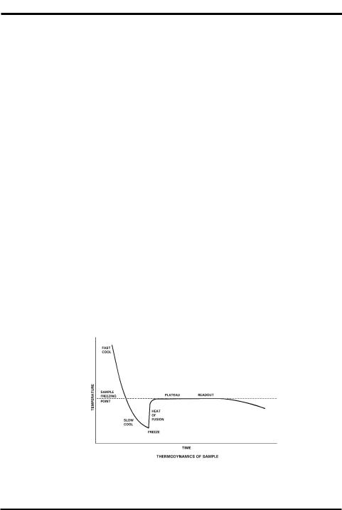
The quickest and most precise way to measure the freezing point of a solution is to supercool it several degrees below its freezing point. It is unstable in this state, and a mechanical agitation induces crystallization. The heat of fusion suddenly liberated causes the sample temperature to rise toward a plateau temperature, where a liquid/solid equilibrium occurs. The equilibrium temperature is, by definition, the freezing point of the solution. Managing the plateau temperature for precise measurement is the basis for several patents issued to Augustus Fiske.
The time over which liquid/solid equilibrium develops and is maintained, is a function of the speed with which the heat-of-fusion is liberated vs. the speed it is transferred away, or absorbed, by the surrounding environment. This ratio can be slowed and the equilibrium time stretched, to give a distinct plateau height measurable to 0.001°C. Sensitive thermistor probes monitor the sample temperature and control the thermoelectric cooling element. Microprocessor control and automated operation minimize imprecision due to operator technique. Figure 1 illustrates the temperature of a sample as it progresses through the freezing cycle and shows the action of the instrument at each stage of the cycle.
Figure 1: Standard Freezing Curve
xvii

The Advanced® Model 3D3 User’s Guide
Definitions
Solution: A homogeneous mixture of solute and solvent in which the solvent is usually the major component, and the solute is the minor component.
Concentration: The ratio of solute to a given amount of solvent (molal), or ratio of solute to solution (molar).
The amount of solute is usually expressed in terms of moles (i.e., gram molecular weights). One mole = 6.028 x 10²³ molecules (Avogadro's number). One mole of glucose (180.2 g) and one mole of sodium chloride (58.4 g) each contain Avogadro's number of molecules.
Common units of concentration are:
•Molality: Moles of solute per kilogram of pure solvent.
•Osmolality: Osmols of solute particles per kilogram of pure solvent. As noted above, most ionic solutes do not completely dissociate. Osmolality is a unit of concentration that takes into account the dissociative effect. Osmolality is usually expressed in mOsm/kg H2O. One milliosmol (mOsm) is 10-3 osmols. Osmolality is defined as:
where:
ø = osmotic coefficient, which accounts for the degree of mole- n cular dissociation.
C= number of particles into which a molecule can dissociate. = molal concentration of the solution.
• Molarity: Moles of solute per liter of solution.
• Osmolarity: Osmols of solute particles per liter of solution.
xviii

Foreword
Although molarity and osmolarity may be common units of measurement in other branches of chemistry, they are not used in osmometry because the ratio of solute to solution is not linear. Molality and osmolality are linear, independent of the effect of temperature and volume displaced by solute. A calculated conversion between units of molality and molarity is complex and generally unnecessary when the terms are properly understood.
Freezing Point/Melting Point: The temperature at which the liquid and solid phases of a substance will remain together in equilibrium.
Freezing-Point Depression: When a solute is added to a solvent, the freezing point of the solvent is lowered. In aqueous solutions, one mOsm of solute per kilogram of water depresses the freezing point by 1.858 millidegrees Celsius (m°C).
Supercooling: The tendency of a substance to remain in the liquid state when cooled below its freezing point.
Crystallization Temperature: Aqueous solutions can be induced to freeze (i.e., crystallize) most reliably when supercooled. When supercooled, agitating the solution (freeze pulse) induces crystal formation. The crystallization temperature is the temperature at which crystallization is induced. During crystallization, the heat of fusion raises the temperature of the sample to an ice/water freezing-point plateau.
Heat of Fusion: The heat released when the mobile molecules of a liquid are frozen into rigid ice crystals.
Freezing-Point Plateau: The constant temperature maintained during the time that ice and liquid exist in isothermal equilibrium after crystallization occurs.
xix

The Advanced® Model 3D3 User’s Guide
Notes:
xx

 Installation & Setup
In order to set up your instrument properly, it is important that you read and follow the steps in this section. Please follow these steps carefullyand be sure to read Chapter 2 — Instrument Operation before attempting to run tests on your instrument.
A. Things to do in advance
1. Prepare bench space. The dimensions of the Advanced 3D3 osmometer are listed in Appendix B. The area beneath the instrument should be kept clear and adequate space should be provided around the top and sides to allow unimpeded air circulation.
2. Locate and test grounded outlet. A three-prong grounded (earthed) 100-130V or 200-250V, 50-60Hz outlet capable of continuously supplying 2 amperes (1 ampere for 200-250V) is required within five feet of the instrument.
WARNING: This instrument must be properly grounded (earthed). The grounding pin of the power plug is connected to the cabinet to provide a noise shield around sensitive components.
If the instrument is not grounded properly, its operation will be impaired and a safety hazard may exist. It is not enough to simply plug the instrument into a grounding outlet. Have the outlet tested. Record the results.
1
The Advanced® Model 3D3 User’s Guide
3.Obtain required items not supplied by the manufacturer:
•Soft, no-lint paper tissues for wiping the sample probe.
•Clean, dry 0.2-mL or 0.25-mL pipette (see Chapter 2, section F).
B. Storage of supplies
Unopened calibration standards and reference solutions should be stored at 39ºF to 86ºF or 4ºC to 30ºC. Expiration dates are printed on the bottle labels. After opening, avoid contamination and evaporation; treat as recommended in Chapters 2 and 3.
The heat transfer fluid supplied with the instrument should be installed as described in section C below. A small amount of heat transfer fluid clings to the outside of each sample tube and some gradually evaporates; another container should be ordered now, in anticipation of its future requirement and may be stored at room temperature.
C. Installation
CAUTION Do not power the 3D3 for the first time until the voltage selection has been checked as instructed in this section.
NOTE Make sure the Supervisor/Operator keyswitch is in the Supervisor position as shown in figure 3, until power-up has been completed as instructed in section D.
Heat Transfer Fluid and Filter Installation
1. Momentarily press the top of the heat transfer compartment door to release the magnetic latch, then pull the door all the way open (see figure 4).
2

Installation & Setup
Quantity
1
1 pack
1 pack
1 pack
1 pack
1
2 bottles
1
1
1
1
1
1
1
Figure 2: Model 3D3 Osmometer and Accessories
Part No. |
Description |
||
3D3 |
The Advanced® Model 3D3 Osmometer |
||
3LA011 |
100 mOsm Standard |
||
3LA151 |
1500 mOsm Standard |
||
3LA301 |
3000 mOsm Standard |
||
3LA029 |
Clinitrol™ 290 mOsm Reference Solution |
||
3LA827 |
1/16” Hex Wrench |
||
3DA811 |
Heat Transfer Fluid |
||
3D3185 |
Operator/Supervisor Keys (set of 2) |
||
|
|
|
Power Cord (as specified) |
3LA702 |
Probe/Stir Alignment Tool |
||
3LA846 |
Sample Tube Rack |
||
|
|
|
Sample Tubes Pack (re-order 500-pack as |
|
|
|
|
|
|
|
3LA825) |
3D35 |
User’s Guide |
||
3D35-6 |
Warranty Card |
||
|
Table 1: |
Model 3D3 Osmometer Packing List |
|
3
The Advanced® Model 3D3 User’s Guide
2. Locate the bagged plastic tubes protruding through the back wall of the compartment. Remove and discard the plastic bag from the ends of the tubes.
3. A heat transfer fluid filter (figure 4, item 6) should already be mounted on the smaller of the two plastic tubes. If replacement is necessary, force the tubular end of the heat transfer fluid filter at least ¼” or 6 mm into the free end of the smaller of the two tubes.
4. Open a bottle of heat transfer fluid.
5. Insert the plastic tube with the heat transfer fluid filter into the bottle of heat transfer fluid so as to locate the filter at the bottom of the bottle for most economical usage of the fluid. The 3D3 will syphon heat transfer fluid into the freezing chamber as needed.
6. Insert the free end of the larger of the two plastic tubes into the neck of the heat transfer fluid container to return the heat transfer fluid to the container for recycling.
CAUTION The open end of the larger plastic tube must be above the surface of the heat transfer fluid for proper circulation if necessary, remove some fluid.
7. Stand the container of heat transfer fluid in the plastic tray in the heat transfer fluid compartment, making sure the filter remains low in the heat transfer fluid.
8. Close the compartment door.
NOTE When the heat transfer fluid level reaches the REPLACE line on the bottle label, discard remaining solution and replace the heat transfer fluid. Continued use when fluid is below this level will change the thermodynamics of the test.
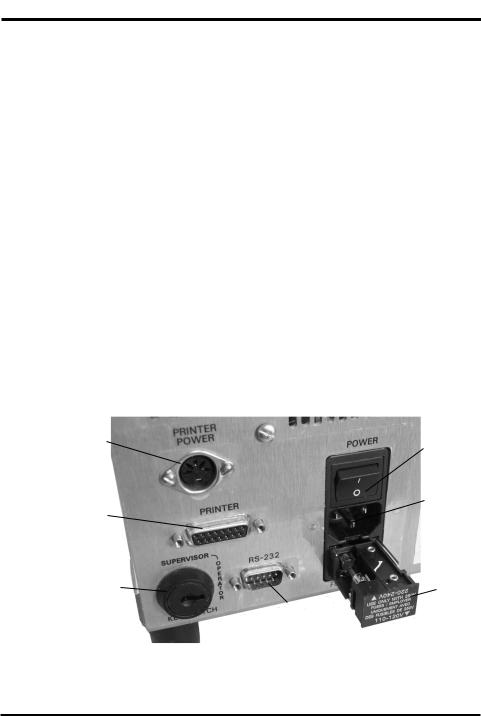
Instrument Voltage Selection (see figure 3)
The 3D3 must be properly set for the voltage available on-site. The onsite power outlet voltage should have been recorded during the procedure recommended in section A.2.
4
Installation & Setup
Check the nominal voltage indicated beside the two matching arrowheads on the voltage selector/fuseholder in the back of the 3D3, below the power switch and power connector.
•If the AC voltage of the power outlet intended for the instrument is within the 100-130V range, the matching arrowheads should indicate 110-120V.
•If the power outlet AC voltage is within the 200-250V range, the matching arrowheads should indicate 220-240V.
•If the voltage selection requires correction, it can be accomplished by matching the proper arrowheads as follows:
1.Unplug the power cord from the back of the instrument.
2.Use a small screwdriver to pry the fuseholder out of the back of the instrument.
3.Check the values marked on the two 5mm x 20mm fuses inside the fuseholder before re-installing. For 100-130V operation they
Printer Power |
|
|
Power |
Outlet |
|
|
|
|
|
Switch |
|
|
|
|
|
|
|
|
Power |
Printer Port |
|
|
Connector |
|
|
|
|
|
|
|
Voltage |
Supervisor/Operator |
|||
Keyswitch |
|
|
Selector |
|
|
|
|
|
|
RS-232 |
|
|
|
Port |
|
Figure 3: Back Panel
5

The Advanced® Model 3D3 User’s Guide
should be 2-Amp fuses; for 200-250V operation they should be 1-Amp fuses. Replace the fuses if incorrect.
4. Re-install the fuseholder into the back of the instrument with the correct arrowheads matching.
5. Connect the power cord to the 3D3 and the power outlet. 6. Proceed to section D below.
D. Power-up
Each time the 3D3 is turned on, it will sequentially display for a few seconds each, the software revision number, copyright notice, serial number, date and time, and the probe bin numbers, similar to the following:
Revision 3D3.A02.0
(C) 1994 A. I., Inc. Serial #:123456789012 03/02/94 08:08 am Block: 5 Sample: 3
Then the operating head will rise and “Press START to Continue” (or its equivalent in French, German or Spanish) will begin to scroll across the display. Maintaining a record of the information displayed will facilitate any necessary service.
All displayed messages will be in the language displayed at this time. To avoid any misunderstanding that might arise due to an unfamiliar display language, use the direct selection SETUP procedure described in Chapter 2, Section C.0 to select setup item 12 and follow the instructions in Chapter 2, Section C.12 to select a different display language.
Power up the 3D3 in the following manner:
6

Installation & Setup
1.If the 3D3 has been installed as instructed in sections A and C, turn the POWER switch on ( I ). The display will begin to scroll.
2.Record the displayed software revision and the block and sample probe bin numbers reported by your instrument in the service log in the back of the user’s guide. The display does not pause for recording. If you need it repeated, turn the instrument off, pause, then turn it on again to reset the instrument.
When all of the instrument data has been displayed, the operating head will rise and “Press START to Continue” will begin to scroll across the display. If for some reason the probe data has been lost from memory, “Reset Probe Configuration” will begin to scroll across the display after the instrument report instead of “Press START to Continue” and one should contact Advanced Instruments’ Hot-Line® service before proceeding further (see Chapter 5, Section B).
3.When “Press START to Continue” begins to scroll across the display, make sure an empty sample tube is in the freezing chamber (figure 4, item 9).
NOTE Step 4 must be accomplished before the 3D3 will cool the first sample.
4.If the instrument is being started for the first time, the heat transfer fluid pump should be “primed” using the TEST menu as follows:
a.Make sure the Supervisor/Operator keyswitch is in the Supervisor position as shown in figure 3.
b.Press the TEST switchpad. The display will change to “Select Test Item”.
c.Press the < switchpad once to step the display backward to “Head Up/Down Test”.
7

The Advanced® Model 3D3 User’s Guide
d. Press the STARTswitchpad. The display will change to “[START] Test [STOP]”.
e. Press the STARTswitchpad.
f. Allow the operating head to cycle down and up approximately twenty times to prime the heat transfer fluid pump. Then press the STOP switchpad to raise the operating head and exit to the test menu.
g. Press the STOP switchpad a second time to exit from the test menu to “Press START to Continue”.
5. With an empty sample tube in the freezing chamber, press the START switchpad.
The microprocessor will respond with the display, “Running Diagnostics”, while it lowers the operating head, cools the freezing chamber and completes a series of internal diagnostic checks. If the diagnostic checks are not successfully completed or the freezing chamber does not cool properly, a diagnostic message will be presented.
If the instrument has just been turned on, it takes a few minutes to cool the freezing chamber. If the heat transfer fluid pump has not been primed as described in step 4, the time will be longer.
When the freezing chamber has been cooled and the internal diagnostic checks have been completed, the operating head rises, “Osmometer Ready” is displayed and an audible tone is sounded. If “Osmometer Ready” is not displayed at this point, turn the instrument off ( O ) for about 5 seconds, then on ( I ) again. If “Osmometer Ready” still does not appear, please refer to Chapter 5 for assistance.
Your 3D3 was calibrated at the factory. The probe and calibration parameters are stored in RAM which is powered by an internal battery when the instrument power is off or disconnected. Thus, when
8
Installation & Setup
“Osmometer Ready” is displayed, your osmometer is calibrated and ready to run.
NOTE If your 3D3 has just been moved from a colder location to its present environment, it should be allowed to warm up for 20 to 30 minutes before assuming that it should be recalibrated.
The 3D3 may be left on continuously. If it remains idle for five minutes or more, it automatically enters standby mode: the fan slows, the freezing chamber warms slightly and the display changes to the date and time. The 3D3 will remain in the standby mode until required to run a freezing-point test. When required to run a freezing-point test, the 3D3 will automatically exit the standby mode, speed up the fan and cool the chamber for the test.
CAUTION If a power interruption occurs, turn the instrument off at once. Leave it turned off for at least 5 seconds after power has been restored (to ensure internal circuitry is restarted properly), even if power restoration is immediate.
Please continue to Chapter 2 for operating instructions.
9

The Advanced® Model 3D3 User’s Guide
Notes:
10
 Loading...