

Page 1

The Advanced®Osmometer
Model 3D3
User ’s Guide
3D35 Rev12 042508
Page 2

The Advanced®Model 3D3 User’s Guide
Copyright
This user’s guide is copyrighted by Advanced Instruments, Inc. with all
rights reserved. Under copyright laws, this guide may not be reproduced
in any form, in whole or part, without the prior written consent of
Advanced Instruments.
© 2003 Advanced Instruments, Inc.
Advanced Instruments has reviewed this guide thoroughly. All material
contained within is believed reliable, but the accuracy and completeness
are not guaranteed or warranted, and are not intended to be representations or warranties concerning the product described.
®
Windows
United States and other countries. All other trademarks are the property
of Advanced Instruments, Inc.
is a registered trademark of Microsoft Corporation in the
Hot-Line®Service
If you have any questions or problems regarding the proper operation of
your instrument, please contact our Hot-Line Service department by
calling one of the following numbers.
• 800-225-4034 (toll-free within the USA and Canada)
• +US 781-320-9000 (elsewhere)
• 781-320-0811 (fax)
ii
Page 3

Table of Contents
Safe Use vii
Parts & Accessories xi
Calibrators & Standards xiii
Foreword: Theory and Technique xv
Principles of Freezing-Point Osmometry xv
Instrumentation xvi
Freezing-Point Thermodynamics xvii
Definitions xviii
Figure 1: Standard Freezing Curve xvii
Chapter 1 — Installation & Setup 1
A. Things to do in advance 1
B. Storage of supplies 2
C. Installation 2
D. Power-up 6
Figure 2: Model 3D3 Osmometer and Acccessories 3
Figure 3: Back Panel 5
Table 1: Model 3D3 Osmometer Packing List 3
Chapter 2 — Instrument Operation 11
Hazardous material cautions 11
A. Function of major components 11
B. Fluid check and startup 18
C. Setup 19
D. Test 28
iii
Page 4

The Advanced®Model 3D3 User’s Guide
E. Sample preparation 28
F. Sample tubes and sample sizes 28
G. Sample test procedure 29
Repeatability tips 33
Figure 4: Model 3D3 Components and Controls 12
Table 2: Communications Port Connections 14
Table 3: Printer Power Connections 15
Table 4: Printer Port Connections 16
Table 5: Setup Menu Options 20
Table 6: Test Mode Options 28
Chapter 3 — Standards & Quality Control 35
A. Purpose of quality control 35
B. Repeatability and accuracy 35
C. Standards and controls 36
D. Maintenance of standards 36
E. Quality control implementation 37
Chapter 4 — Calibration 39
Chapter 5 — Troubleshooting & Service 43
A. Service & maintenance cautions 43
B. Obtaining service 44
C. Routine maintenance 45
D. Shutdown and storage 46
E. Troubleshooting 46
F. Test 48
G. Adjustment and replacement of parts and assemblies 55
Figure 5: Operating Head 57
Figure 6: Mandrel, Probe and Stir/Freeze Wire Adjustment 61
iv
Page 5

Table of Contents
Appendices 67
Appendix A — Troubleshooting table 67
Appendix B — Product specifications 79
Appendix C — Regulatory notices 81
Appendix D — Warranty and warranty duties 83
Appendix E — Supplemental RS-232 information 87
Appendix F — Symbol definitions 89
Appendix G — Service log 93
Figure 7: RS-232 External Cable 88
Index 95
v
Page 6

The Advanced®Model 3D3 User’s Guide
Notes:
vi
Page 7
Safe Use
To reduce the risk of bodily injury, electric shock, fire, and
damage to your instrument, please read and observe the precautions in this User’s Guide.
• If the product is used in a manner not in accordance with the
equipment design, operating instructions or manufacturer's
recommendations, the operation of the product may be
impaired to the extent that a safety hazard is created.
• Do not attempt to perform electrical work if you are not
fully qualified. This manual is not a substitute for electrical
training.
Symbol conventions
The exclamation point within an equilateral triangle is
intended to alert the user to the presence of important operating and maintenance (servicing) instructions in the literature accompanying this product.
The lightning flash with arrowhead symbol within an equilateral triangle is intended to alert the user to the presence of
uninsulated dangerous voltage within the product's enclosure
that may be of sufficient magnitude to constitute risk of
electric shock to persons.
The static symbol within an equilateral triangle is intended
to alert the user to the presence of internal components that
could be damaged by static electricity.
This static symbol is intended to alert the user to the presence of a specific component that could be damaged by static electricity.
vii
Page 8

The Advanced®Model 3D3 User’s Guide
This symbol indicates the presence of alternating current (AC).
This symbol indicates the presence of a fuse.
This symbol indicates the presence of protective earth ground.
General cautions
• This product should be operated only with the type of power source
indicated on the product’s electrical ratings label. Refer to the installation instructions included with the product.
• If the power cord provided is replaced for any reason or if an alternate cord is used, the cord must be approved for use in the local
country. The power cord must be approved for the product’s listed
operating voltage and be rated at least 20% greater than the ampere
ratings marked on the product’s electrical ratings label. The cord
end that connects to the product must have an IEC 60320 connector.
• Plug the product into an approved grounded electrical outlet.
• Do not disable the power cord’s grounding plug.
• If an extension cord or power strip is used, make sure that the cord
or strip is rated for the product, and that the total ampere ratings of
all products plugged into the extension cord or strip do not exceed
80% of the cord’s or strip’s rating limit.
• Route power cords so that they will not be walked on, tripped on, or
pinched by items placed upon or against them. Pay particular attention to the plug, electrical outlet, and the point where the cord exits
the product.
• Do not pull on cords and cables. When unplugging cords or cables,
grasp the corresponding connector.
viii
Page 9

Safe Use
• Do not install or use this product in any area subject to extreme
short-term temperature variations, or locations that exceed the specified operating environment temperatures.
• Never use this product in a wet area.
• To avoid injury or fire hazard, do not operate this product in an
explosive atmosphere.
• Do not install or use the product on an unstable, non-level work surface.
• Do not operate this product with the covers removed or unsecured.
ix
Page 10

The Advanced®Model 3D3 User’s Guide
Notes:
x
Page 11

Parts & Accessories
To order parts and accessories, contact the Advanced
Instruments Customer Service Department by using one of the
following numbers.
• 800-225-4034 (toll-free within the USA and Canada)
• +US 781-320-9000 (elsewhere)
• 781-320-3669 (fax)
PART DESCRIPTION
1-Amp Time Delay (T) Fuse for 200-250V
2-Amp Time Delay (T) Fuse for 100-130V
Clapper
Disposable Air Filters
Disposable Sample Tubes, 0.2 or 0.25 mL
Thermal Printer with Interface Cable, Operation Manual,
Thermal Paper Roll, and Printer Power Supply (100-120
VAC)
Thermal Printer with Interface Cable, Operation Manual,
Thermal Paper Roll, and Printer Power Supply (230 VAC)
Heat Transfer Fluid
Heat Transfer Fluid Filter
Mandrel
Operator/Supervisor Keys
Power Cord (specify voltage and country)
Printer Paper (5 rolls)
PART NO.
7011
7022
3C2241
3D2340
3LA825
3D3555_NA
3D3555_EU
3DA811
4S0710
3LH500
3D3185
3D3835
xi
Page 12

The Advanced®Model 3D3 User’s Guide
PART DESCRIPTION
Probe/Stir Wire Alignment Tool
Replacement Sample Probe with Mandrel and three 10-mL
ampules of Probe Bin Setting Fluid (Stainless Steel)
Sample Tube Rack
Serial Port Interface Computer Cable Computer
Connector, 3 Meters
Serial Port Interface Computer Cable Computer
Connector, 6 Meters
Serial Port Interface Computer Cable Computer
Connector, 9 Meters
Service Manual, 3D3/4D3
Stir/Freeze Coil
Stir/Freeze Wires
User’s Guide
Yoke
PART NO.
3LA700
3D3700
3LA846
3M3053
3M3056
3M3059
4D35SM
3D2404
3LH243
3D35
3LH230
xii
Page 13

Calibrators & Standards
To order calibrators and standards, contact the Advanced
Instruments Customer Service Department by using one of the
following numbers.
• 800-225-4034 (toll-free within the USA and Canada)
• +US 781-320-9000 (elsewhere)
• 781-320-3669 (fax)
DESCRIPTION
ClinitrolTMmOsm/kg Reference Solution (10 5mL ampules)
Five-Level Osmolality Linearity Set: 100, 500, 900, 1500
and 2000 mOsm (10 5mL ampules, 2 of each value)
Protinol®3-Level Protein Control Kit (9 3mL bottles, 3 of
each level)
Renol™ Urine Osmolality Controls (2 levels)
100 mOsm/kg Calibration Standard (110mL bottle)
100 mOsm/kg Calibration Standard (10 5mL ampules)
500 mOsm/kg Calibration Standard (110mL bottle)
500 mOsm/kg Calibration Standard (10 5mL ampules)
900 mOsm/kg Calibration Standard (110mL bottle)
900 mOsm/kg Calibration Standard (10 5mL ampules)
1500 mOsm/kg Calibration Standard (110mL bottle)
1500 mOsm/kg Calibration Standard (10 5mL ampules)
2000 mOsm/kg Calibration Standard (10 5mL ampules)
PART NO.
3LA029
3LA028
3MA028
3LA085
3LA010
3LA011
3LA050
3LA051
3LA090
3LA091
3LA150
3LA151
3LA201
3000 mOsm/kg Calibration Standard (10 5mL ampules)
3LA301
xiii
Page 14

The Advanced®Model 3D3 User’s Guide
Notes:
xiv
Page 15

Foreword
Principles of Freezing-Point Osmometry
When a solute is dissolved in a pure solvent, the following
changes in the solution's properties occur:
• the freezing point is depressed,
• boiling point is raised,
• osmotic pressure is increased, and
• vapor pressure is lowered.
These are the so-called "colligative" or concentrative properties
of the solution which, within reasonable limits, change in direct
proportion to the solute concentration; in other words, the number of particles in solution.
Of the colligative properties, measurement of the freezing point
allows the concentration of an aqueous solution to be easily
determined with great precision.
The freezing point of pure H
mole of a non-dissociating solute such as glucose (where the
solute does not dissociate into ionic species, but remains intact),
when dissolved in 1 kilogram (kg) of water will depress the
freezing point by 1.858°C. This change is known as the freezing point depression constant for water. The freezing point
depression also depends upon the degree of dissociation of the
2O is precisely +0.010°C. One
xv
Page 16

The Advanced®Model 3D3 User’s Guide
solute. If the solute is ionic, the freezing point is depressed by 1.858°C
for each ionic species. For example, if one mole of sodium chloride
were to completely dissociate into two ionic species (Na+ and Cl-) in 1
kg of water, the freezing point would be depressed by 3.716°C.
However, dissociation is never complete. Interference between solute
molecules reduces dissociation by a factor called the osmotic coefficient.
In a simple solution such as glucose or sodium chloride in water, the
freezing point can be measured and the unit concentration easily determined from an equation or a reference table. However, the equation is
unique for each solute. In a more complex solution, all ionized and
non-dissociated species contribute to the freezing-point depression and
the concentration of each solute cannot be easily determined.
Each of the colligative properties has a similar problem, and though
each of the colligative properties changes in direct proportion to the
solute concentration, each requires a different mode & unit of measurement. Osmolality is a common unit of concentration measurement that
can be used to relate all the colligative properties to each other, and to
other concentration units. Because of its universality, most osmometry
applications regularly use osmolality, expressed as "mOsm/kg H
2O", as
the common unit of concentration rather than applying further conversion factors.
Instrumentation
Advanced Osmometers are devices for the determination of the concentration of solutions by means of freezing-point measurement.
Advanced Osmometers utilize high-precision thermometers to sense the
sample temperature, to control the degree of supercooling and freeze
induction, and to measure the freezing point of the sample. They can
routinely determine differences of ±1 mOsm/kg H
xvi
2O.
Page 17
Foreword
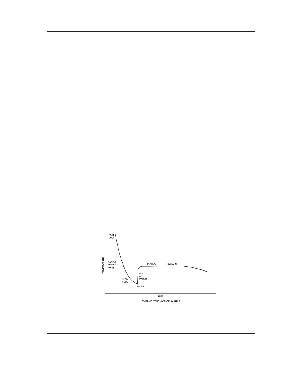
Freezing-Point Thermodynamics
The quickest and most precise way to measure the freezing point of a
solution is to supercool it several degrees below its freezing point. It is
unstable in this state, and a mechanical agitation induces crystallization.
The heat of fusion suddenly liberated causes the sample temperature to
rise toward a plateau temperature, where a liquid/solid equilibrium
occurs. The equilibrium temperature is, by definition, the freezing point
of the solution. Managing the plateau temperature for precise measurement is the basis for several patents issued to Augustus Fiske.
The time over which liquid/solid equilibrium develops and is maintained, is a function of the speed with which the heat-of-fusion is liberated vs. the speed it is transferred away, or absorbed, by the surrounding
environment. This ratio can be slowed and the equilibrium time
stretched, to give a distinct plateau height measurable to 0.001°C.
Sensitive thermistor probes monitor the sample temperature and control
the thermoelectric cooling element. Microprocessor control and automated operation minimize imprecision due to operator technique.
Figure 1 illustrates the temperature of a sample as it progresses through
the freezing cycle and shows the action of the instrument at each stage
of the cycle.
Figure 1: Standard Freezing Curve
xvii
Page 18

The Advanced®Model 3D3 User’s Guide
Definitions
Solution: A homogeneous mixture of solute and solvent in which the
solvent is usually the major component, and the solute is the minor
component.
Concentration: The ratio of solute to a given amount of solvent
(molal), or ratio of solute to solution (molar).
The amount of solute is usually expressed in terms of moles (i.e., gram
3
2
molecular weights). One mole = 6.028 x 10
molecules (Avogadro's
number). One mole of glucose (180.2 g) and one mole of sodium chloride (58.4 g) each contain Avogadro's number of molecules.
Common units of concentration are:
• Molality: Moles of solute per kilogram of pure solvent.
• Osmolality: Osmols of solute particles per kilogram of pure solvent. As noted above, most ionic solutes do not completely dissociate. Osmolality is a unit of concentration that takes into
account the dissociative effect. Osmolality is usually expressed
-3
in mOsm/kg H2O. One milliosmol (mOsm) is 10
osmols.
Osmolality is defined as:
where:
ø = osmotic coefficient, which accounts for the degree of mole-
cular dissociation.
n = number of particles into which a molecule can dissociate.
C = molal concentration of the solution.
• Molarity: Moles of solute per liter of solution.
• Osmolarity: Osmols of solute particles per liter of solution.
xviii
Page 19

Foreword
Although molarity and osmolarity may be common units of
measurement in other branches of chemistry, they are not used in
osmometry because the ratio of solute to solution is not linear.
Molality and osmolality are linear, independent of the effect of
temperature and volume displaced by solute. A calculated conversion between units of molality and molarity is complex and
generally unnecessary when the terms are properly understood.
Freezing Point/Melting Point: The temperature at which the liquid
and solid phases of a substance will remain together in equilibrium.
Freezing-Point Depression: When a solute is added to a solvent, the
freezing point of the solvent is lowered. In aqueous solutions, one
mOsm of solute per kilogram of water depresses the freezing point by
1.858 millidegrees Celsius (m°C).
Supercooling: The tendency of a substance to remain in the liquid
state when cooled below its freezing point.
Crystallization Temperature: Aqueous solutions can be induced to
freeze (i.e., crystallize) most reliably when supercooled. When supercooled, agitating the solution (freeze pulse) induces crystal formation.
The crystallization temperature is the temperature at which crystallization is induced. During crystallization, the heat of fusion raises the
temperature of the sample to an ice/water freezing-point plateau.
Heat of Fusion: The heat released when the mobile molecules of a liquid are frozen into rigid ice crystals.
Freezing-Point Plateau: The constant temperature maintained during
the time that ice and liquid exist in isothermal equilibrium after crystallization occurs.
xix
Page 20

The Advanced®Model 3D3 User’s Guide
Notes:
xx
Page 21

1
Installation & Setup
In order to set up your instrument properly, it is important that
you read and follow the steps in this section. Please follow these
steps carefully and be sure to read Chapter 2 — Instrument
Operation before attempting to run tests on your instrument.
A. Things to do in advance
1. Prepare bench space. The dimensions of the Advanced
3D3 osmometer are listed in Appendix B. The area beneath
the instrument should be kept clear and adequate space
should be provided around the top and sides to allow unimpeded air circulation.
2. Locate and test grounded outlet. A three-prong grounded
(earthed) 100-130V or 200-250V, 50-60Hz outlet capable of
continuously supplying 2 amperes (1 ampere for 200-250V)
is required within five feet of the instrument.
WARNING: This instrument must be properly grounded
(earthed). The grounding pin of the power plug is connected
to the cabinet to provide a noise shield around sensitive
components.
If the instrument is not grounded properly, its operation will
be impaired and a safety hazard may exist. It is not enough
to simply plug the instrument into a grounding outlet. Have
the outlet tested. Record the results.
1
Page 22

The Advanced®Model 3D3 User’s Guide
3. Obtain required items not supplied by the manufacturer:
• Soft, no-lint paper tissues for wiping the sample probe.
• Clean, dry 0.2-mL or 0.25-mL pipette (see Chapter 2, section F).
B. Storage of supplies
Unopened calibration standards and reference solutions should be stored
at 39ºF to 86ºF or 4ºC to 30ºC. Expiration dates are printed on the bottle labels. After opening, avoid contamination and evaporation; treat as
recommended in Chapters 2 and 3.
The heat transfer fluid supplied with the instrument should be installed
as described in section C below. A small amount of heat transfer fluid
clings to the outside of each sample tube and some gradually evaporates; another container should be ordered now, in anticipation of its
future requirement and may be stored at room temperature.
C. Installation
CAUTION Do not power the 3D3 for the first time until the volt-
age selection has been checked as instructed in this
section.
NOTE Make sure the Supervisor/Operator keyswitch is in the
Supervisor position as shown in figure 3, until power-up
has been completed as instructed in section D.
Heat Transfer Fluid and Filter Installation
1. Momentarily press the top of the heat transfer compartment door to
release the magnetic latch, then pull the door all the way open (see
figure 4).
2
Page 23
Installation & Setup
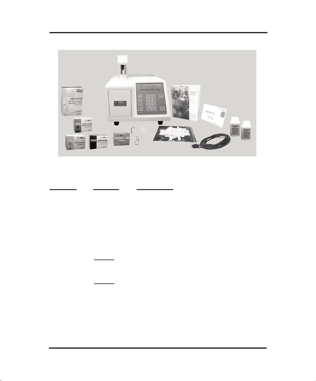
Figure 2: Model 3D3 Osmometer and Accessories
Quantity Part No. Description
1 3D3 The Advanced®Model 3D3 Osmometer
1 pack 3LA011 100 mOsm Standard
1 pack 3LA151 1500 mOsm Standard
1 pack 3LA301 3000 mOsm Standard
1 pack 3LA029 Clinitrol™ 290 mOsm Reference Solution
1 3LA827 1/16” Hex Wrench
2 bottles 3DA811 Heat Transfer Fluid
1 3D3185 Operator/Supervisor Keys (set of 2)
1 Power Cord (as specified)
1 3LA702 Probe/Stir Alignment Tool
1 3LA846 Sample Tube Rack
1 Sample Tubes Pack (re-order 500-pack as
3LA825)
1 3D35 User’s Guide
1 3D35-6 Warranty Card
Table 1: Model 3D3 Osmometer Packing List
3
Page 24

The Advanced®Model 3D3 User’s Guide
2. Locate the bagged plastic tubes protruding through the back wall of
the compartment. Remove and discard the plastic bag from the
ends of the tubes.
3. A heat transfer fluid filter (figure 4, item 6) should already be
mounted on the smaller of the two plastic tubes. If replacement is
necessary, force the tubular end of the heat transfer fluid filter at
least ¼” or 6 mm into the free end of the smaller of the two tubes.
4. Open a bottle of heat transfer fluid.
5. Insert the plastic tube with the heat transfer fluid filter into the bottle of heat transfer fluid so as to locate the filter at the bottom of
the bottle for most economical usage of the fluid. The 3D3 will
syphon heat transfer fluid into the freezing chamber as needed.
6. Insert the free end of the larger of the two plastic tubes into the
neck of the heat transfer fluid container to return the heat transfer
fluid to the container for recycling.
CAUTION The open end of the larger plastic tube must be above
the surface of the heat transfer fluid for proper circulation if necessary, remove some fluid.
7. Stand the container of heat transfer fluid in the plastic tray in the
heat transfer fluid compartment, making sure the filter remains
low in the heat transfer fluid.
8. Close the compartment door.
NOTE When the heat transfer fluid level reaches the REPLACE line
on the bottle label, discard remaining solution and replace the
heat transfer fluid. Continued use when fluid is below this
level will change the thermodynamics of the test.
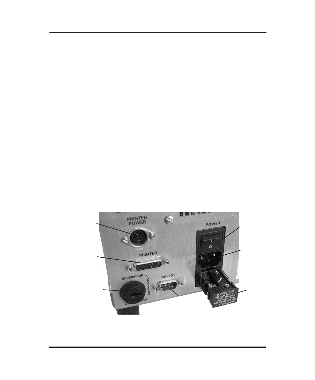
Instrument Voltage Selection (see figure 3)
The 3D3 must be properly set for the voltage available on-site. The onsite power outlet voltage should have been recorded during the procedure recommended in section A.2.
4
Page 25
Installation & Setup
Check the nominal voltage indicated beside the two matching arrowheads on the voltage selector/fuseholder in the back of the 3D3, below
the power switch and power connector.
• If the AC voltage of the power outlet intended for the instrument is
within the 100-130V range, the matching arrowheads should indicate
110-120V.
• If the power outlet AC voltage is within the 200-250V range, the
matching arrowheads should indicate 220-240V.
• If the voltage selection requires correction, it can be accomplished
by matching the proper arrowheads as follows:
1. Unplug the power cord from the back of the instrument.
2. Use a small screwdriver to pry the fuseholder out of the back of
the instrument.
3. Check the values marked on the two 5mm x 20mm fuses inside
the fuseholder before re-installing. For 100-130V operation they
Printer Power
Outlet
Printer Port
Supervisor/Operator
Keyswitch
Power
Switch
Power
Connector
Voltage
Selector
RS-232
Port
Figure 3: Back Panel
5
Page 26

The Advanced®Model 3D3 User’s Guide
should be 2-Amp fuses; for 200-250V operation they should be
1-Amp fuses. Replace the fuses if incorrect.
4. Re-install the fuseholder into the back of the instrument with the
correct arrowheads matching.
5. Connect the power cord to the 3D3 and the power outlet.
6. Proceed to section D below.
D. Power-up
Each time the 3D3 is turned on, it will sequentially display for a few
seconds each, the software revision number, copyright notice, serial
number, date and time, and the probe bin numbers, similar to the following:
Revision
3D3.A02.0
(C) 1994 A. I., Inc.
Serial #:123456789012
03/02/94 08:08 am
Block: 5 Sample: 3
Then the operating head will rise and “Press START to Continue” (or
its equivalent in French, German or Spanish) will begin to scroll across
the display. Maintaining a record of the information displayed will
facilitate any necessary service.
All displayed messages will be in the language displayed at this time.
To avoid any misunderstanding that might arise due to an unfamiliar
display language, use the direct selection SETUP procedure described in
Chapter 2, Section C.0 to select setup item 12 and follow the instructions in Chapter 2, Section C.12 to select a different display language.
Power up the 3D3 in the following manner:
6
Page 27

Installation & Setup
1. If the 3D3 has been installed as instructed in sections A and C, turn
the POWER switch on ( I ). The display will begin to scroll.
2. Record the displayed software revision and the block and sample
probe bin numbers reported by your instrument in the service log in
the back of the user’s guide. The display does not pause for recording. If you need it repeated, turn the instrument off, pause, then turn
it on again to reset the instrument.
When all of the instrument data has been displayed, the operating
head will rise and “Press START to Continue” will begin to scroll
across the display. If for some reason the probe data has been lost
from memory, “Reset Probe Configuration” will begin to scroll
across the display after the instrument report instead of “Press
START to Continue” and one should contact Advanced
Instruments’ Hot-Line
®
service before proceeding further (see
Chapter 5, Section B).
3. When “Press START to Continue” begins to scroll across the dis-
play, make sure an empty sample tube is in the freezing chamber
(figure 4, item 9).
NOTE Step 4 must be accomplished before the 3D3 will cool the
first sample.
4. If the instrument is being started for the first time, the heat transfer
fluid pump should be “primed” using the TEST menu as follows:
a. Make sure the Supervisor/Operator keyswitch is in the Supervisor
position as shown in figure 3.
b. Press the TEST switchpad. The display will change to “Select
Test Item”.
c. Press the < switchpad once to step the display backward to
“Head Up/Down Test”.
7
Page 28

The Advanced®Model 3D3 User’s Guide
d. Press the START switchpad. The display will change to
“[START] Test [STOP]”.
e. Press the START switchpad.
f. Allow the operating head to cycle down and up approximately
twenty times to prime the heat transfer fluid pump. Then press
the STOP switchpad to raise the operating head and exit to the
test menu.
g. Press the STOP switchpad a second time to exit from the test
menu to “Press START to Continue”.
5. With an empty sample tube in the freezing chamber, press the
START switchpad.
The microprocessor will respond with the display, “Running
Diagnostics”, while it lowers the operating head, cools the freezing
chamber and completes a series of internal diagnostic checks. If
the diagnostic checks are not successfully completed or the freezing
chamber does not cool properly, a diagnostic message will be presented.
If the instrument has just been turned on, it takes a few minutes to
cool the freezing chamber. If the heat transfer fluid pump has not
been primed as described in step 4, the time will be longer.
When the freezing chamber has been cooled and the internal diagnostic checks have been completed, the operating head rises,
“Osmometer Ready” is displayed and an audible tone is sounded.
If “Osmometer Ready” is not displayed at this point, turn the instrument off ( O ) for about 5 seconds, then on ( I ) again. If
“Osmometer Ready” still does not appear, please refer to Chapter 5
for assistance.
Your 3D3 was calibrated at the factory. The probe and calibration parameters are stored in RAM which is powered by an internal battery
when the instrument power is off or disconnected. Thus, when
8
Page 29

Installation & Setup
“Osmometer Ready” is displayed, your osmometer is calibrated and
ready to run.
NOTE If your 3D3 has just been moved from a colder location to its
present environment, it should be allowed to warm up for 20 to
30 minutes before assuming that it should be recalibrated.
The 3D3 may be left on continuously. If it remains idle for five minutes
or more, it automatically enters standby mode: the fan slows, the freezing chamber warms slightly and the display changes to the date and
time. The 3D3 will remain in the standby mode until required to run a
freezing-point test. When required to run a freezing-point test, the 3D3
will automatically exit the standby mode, speed up the fan and cool the
chamber for the test.
CAUTION If a power interruption occurs, turn the instrument off at
once. Leave it turned off for at least 5 seconds after power
has been restored (to ensure internal circuitry is restarted
properly), even if power restoration is immediate.
Please continue to Chapter 2 for operating instructions.
9
Page 30

The Advanced®Model 3D3 User’s Guide
Notes:
10
Page 31

2
Instrument Operation
In order to run your instrument properly, it is important that
you read and adhere to the instructions in this section. For
information on calibration, see Chapter 4 — Calibration.
Hazardous material cautions
• WARNING: Handle all biohazardous materials according to
established good laboratory practices and follow your institution’s exposure control plan. Persons handling human blood
and body fluid samples must be trained in blood-borne hazards
and observe universal precautions. Universal precautions is an
approach to infection control, where all human blood and body
fluids are treated as if known to be infectious. Use personal
protective equipment such as gloves, gowns, etc., to prevent
exposure. Store biohazardous materials in regulated waste containers and dispose of these materials in a safe and acceptable
manner that is in compliance with all country, state and local
requirements.
• If a biohazardous material is spilled on or inside the equipment,
decontaminate the equipment using a 1% bleach solution, or as
outlined by those policies and procedures established within
your institution.
• To avoid injury or fire hazard, do not operate this product in an
explosive atmosphere.
A. Function of major components
Operation of the instrument will be quicker and easier if you
become familiar with the locations and functions of the components, systems and controls described below before proceeding further.
11
Page 32

The Advanced®Model 3D3 User’s Guide
Power Switch, Fuse
Holder, and RS-232
Connector on Back
Panel
Freezing
Chamber (9)
Air Filter (8)
Heat Transfer
Fluid Filter (6)
Replace Heat
Transfer Fluid
Filter Line (7)
Operating Head (2)
Stir/Freeze Wire (3)
Sample Probe (4)
Display Panel
and Keypad (5)
Figure 4: Model 3D3 Components and Controls
Functionally, this instrument consists of automatic sample holding and
centering devices, a microprocessor-controlled freezing chamber, a precision digital thermometer, measurement and control circuitry and a
message display panel. These basic systems include the following parts
and controls:
1. Power Entry Module (see figure 3): Contains the following power
components:
a. Power switch: Press "I" for power on, "O" for power off. The
power may be left on continuously; the 3D3 enters standby mode
automatically if idle for more than five minutes.
b. Power cord connector: To accommodate a power cord suitable
for the power available.
c. Fuse holder/voltage selector: For containing fuses suitable for
the power available and for selecting the proper voltage (see
Chapter 1, Section C).
12
Page 33

Instrument Operation
2. Supervisor/Operator Keyswitch (see figure 3): The Operator
position of the Supervisor/Operator keyswitch provides a means
of locking out the setup, test and calibration functions of the instrument to help prevent unauthorized changes.
The Operator keyswitch position allows access to the sample test
function only; the Supervisor keyswitch position allows access to
the setup, test and calibration functions, as well as the sample test
function. It may be necessary or desirable, therefore, to complete
some SETUP or TEST function (e.g., to prime the heat transfer
pump as in Chapter 1, Section D.4) before locking the
Supervisor/Operator keyswitch in the Operator position.
If the SETUP or TEST switchpad is pressed while the
Supervisor/Operator keyswitch is in the Operator position, a
"Supervisor Key Needed; Press STOP to Continue" message is
continually scrolled across the display until STOP is pressed.
When STOP is pressed, the message will change back to "Ready",
re-enabling the sample test function.
The CALIB switchpad has no effect until the instrument has completed the power-up diagnostic checks. If the CALIB switchpad is
pressed after the instrument has completed the power-up diagnostic
checks and the Supervisor/Operator keyswitch is in the Operator
position, a "Supervisor Key Needed; Press STOP to Continue"
message is continuously scrolled across the display until STOP is
pressed.
3. RS-232 Port (see figure 3): The DB-9 RS-232 port conforms to the
DTE RS-232C standard and has the following pin assignments (see
table on next page).
The serial port can reliably communicate over cable up to 10 meters
in length. Data is transmitted asynchronously as 1 start bit, 8 data
bits and 1 stop bit, with no parity. Hardware handshaking is
supported; XON-XOFF software handshaking may be selected by
means of the SETUP menu (see section C.7).
13
Page 34

The Advanced®Model 3D3 User’s Guide
Signal Pin Direction
Carrier Detect 1 to 3D3
Receive Data 2 to 3D3
Transmit Data 3 from 3D3
Data Terminal Ready 4 from 3D3
Signal Ground 5 common
Data Set Ready 6 to 3D3
Request to Send 7 from 3D3
Clear to send 8 to 3D3
Table 2: Communications Port Connections
The default serial data rate is 1200 bps (bits per second), though
300 bps and 9600 bps may alternatively be selected (see section
C.7).
Each message transmitted from the serial port is terminated by the
sequence, Carriage Return (0D Hex), Line Feed (0A Hex), Null (00
Hex). For display purposes, most messages consist of less than 20
characters but longer messages, which scroll across the display, are
transmitted no differently.
The 3D3 transmits a significant amount of information via the RS232 port. Almost every item of information displayed by the instrument is transmitted over the RS-232 port, including test results, all
error messages, and most display data from the "test" menu (see
Chapter 5, Section F).
4. Printer Power Outlet (see figure 3): A 3-pin DIN socket on the
back of the 3D3 automatically provides the proper power for the
optional Advanced Instruments printer listed in Table 3 (if cable
supplied with printer).
14
Page 35

Instrument Operation
Printer Power Connections
Pin 1 (left) +12 VDC
Pin 2 (center) not connected
Pin 3 (right) ground
Table 3: Printer Power Connections
5. Printer Port (see figure 3): The printer port connector on the back
of the 3D3 provides 8 data lines and the necessary handshaking signals for communication with most standard printers. The printer
port connections are listed in Table 4.
NOTE If the printer does not print, make sure to check both the
printer power and parallel cable connections before requesting service assistance as recommended in Chapter 5,
Section B.
6. Freezing Chamber (figure 4, item 9): The freezing chamber is
thermoelectric for reliability and precise control. The chamber contains a small amount of heat transfer fluid for optimum cooling
capacity.
7. Operating Head (figure 4, item 2): The operating head contains a
stir/freeze wire (item 3) with electrical means to vibrate it; an ultrastable, ultra-precise thermistor sample probe (item 4) with devices
to automatically locate the probe and sample in the freezing chamber.
8. Measurement and Control Circuits (inside): Microprocessor controlled. Provide operating mode and calibration selections on the
display during SETUP. Automatically measure and control the
dynamic temperature of the sample freezing chamber. Process calibration data and sample temperature information. Present calibrated
test results on the digital display.
15
Page 36

The Advanced®Model 3D3 User’s Guide
PIN-OUT
SIGNAL
Port
Connector
Cable
Output
STROBE
Data 0
Data 1
Data 2
Data 3
Data 4
Data 5
Data 6
Data 7
READY
Ret. Gnd
Ret. Gnd
Ret. Gnd
Ret. Gnd
Ret. Gnd
8
2
3
4
5
6
14
7
15
1
9
10
11
12
13
1
2
3
4
5
6
7
8
9
11
19
20
21
22
23
Table 4: Printer Port Connections
9. Display Panel and Keypad (figure 4, item 5): The microprocessor
communicates with the instrument operator by means of alphanumeric messages displayed on the illuminated display panel located at the top of the keypad. These messages report the instrument
function currently being performed, the next operator function
required and the results of tests. The messages are displayed either
in English, French, German or Spanish, as selected via the SETUP
menu (see section C.12); the default language is English.
16
Page 37

Instrument Operation
The keypad contains spill-proof delineated pressure pads for operator input to the micro-processor. Keypad switch activation requires
firm finger pressure to the center of the pad. When pressed properly the RECALL, SETUP, TEST, CALIB, START and STOP pads
illuminate to indicate activation.
The function of each of the switchpads is as follows:
a. RECALL: Recalls the previous display (the last test result or
the last message).
b. SETUP: Activates the SETUP menu which may be used to set
the current date and time, activate the keypad "beeper", select
the serial-port communication parameters, etc. (see section C).
c. CALIB: Activates calibration prompts for calibration of the
instrument. Pressing STOP during a calibration test will cancel
the test in progress; pressing STOP a second time will cancel
recalibration and retain the previous calibration.
d. TEST: Activates a "test" menu for checking selected compo-
nents and subsystems (see section D).
e. Numbers 1 through 0: Allow prompted numeric operator
input, as required, during SETUP, CALIB and TEST procedures.
f. < and > : Allow stepping forward and backward through dis-
played menu items as an alternative to selection via the numeric
pads and allows making alternative two-item menu choices.
g. CLEAR: Can be used to empty the date and time memory
fields during SETUP. If sample identification has been
enabled, CLEAR can also be used to empty the sample identification memory field.
17
Page 38

The Advanced®Model 3D3 User’s Guide
h. ENTER: Confirms the selected SETUP menu item. If sample
identification has been enabled, ENTER is used to confirm the
sample identification.
i. START: Starts CALIB, TEST and SET-UP procedures, as
well as freezing-point tests.
j. STOP: Cancels the procedure in process. During multiple step
procedures such as calibration, pressing STOP once cancels the
current test; pressing STOP a second time cancels the procedure.
B. Fluid check and startup
Momentarily press the top of the heat transfer compartment door to
release the magnetic latch, then pull the door all the way open (see figure 4).
A container of heat transfer fluid and a heat transfer fluid filter are supplied with the 3D3 and should have been installed as instructed in
Chapter 1, Section C. Two plastic tubes of different sizes should be
observed, extending into the mouth of a container of heat transfer fluid.
The heat transfer fluid level should be visible through the semi-transparent container; if the heat transfer fluid level is below the "REPLACE"
line marked on the container, it should be replaced. When finished,
close the heat transfer fluid compartment door.
CAUTION The open end of the larger plastic tube must be above the
surface of the heat transfer fluid for proper circulation; if
necessary, remove some fluid.
If the date and time are being displayed, the 3D3 is in the standby
mode, ready for a test to be run.
18
Page 39

Instrument Operation
If the power switch on the back of the instrument is in the off ( O ) position and the power cord is connected to the 3D3 and the power outlet,
place the power switch in the on ( I ) position.
Each time the 3D3 is turned on, it sequentially displays, for a few seconds each, the software revision number, copyright notice, serial number, date and time and the probe bin numbers. Then "Press START to
Continue" will begin to scroll across the display.
Make sure an empty sample tube is in the freezing chamber (figure 4,
item 9); then press the START switchpad. The microprocessor will
respond with the display, "Running Diagnostics", while it lowers the
operating head, cools the freezing chamber and completes a series of
internal diagnostic checks. If the instrument has just been turned on, it
will take a few minutes to cool the freezing chamber.
When the freezing chamber has been cooled and the internal diagnostic
checks have been completed, the operating head rises, "Osmometer
Ready" is displayed and an audible tone is sounded.
C. Setup
Your 3D3 has been individually setup at the factory for normal operation, but SETUP may be required for changing the date and time or customizing the SETUP parameters for your own individual needs.
NOTE The Supervisor/Operator keyswitch must be in the Supervisor
position to enable the use of the SETUP menu. If the SETUP
switchpad is pressed while the Supervisor/Operator keyswitch
is in the Operator position a "Supervisor Key Needed; Press
STOP" message will be displayed (see section A.2).
The operating parameters that may be checked and set via SETUP are as
follows, listed in numerical order.
19
Page 40

The Advanced®Model 3D3 User’s Guide
Setup Menu Options
0. Select Setup Item
1. Set Block Bin #
2. Set Sample Bin #
3. Dis/Enable I.D. #
4. Set Stir Amplitude
5. Set Date/Time
6. Dis/Enable Beeper
7. Set Serial Rate
Enter SETUP, if required, at
"Osmometer Ready" or the
date and time display, by
pressing the SETUP switchpad. When SETUP is
pressed, the display will
change to "Select Setup
Item".
8. Dis/Enable Xon/Xoff
9. Serial Number
10. Select Range
11. Select "Buzz" Point
12. Select Language
There are two ways to select a
SETUP menu item, direct
selection and sequential selection, as described below:
13. Product/Test
Table 5: Setup Menu Options
0. Select Setup Item
This menu item is displayed first when SETUP is pressed and
allows either direct selection or sequential selection of a menu item.
Direct Selection: for direct selection, press START at "Select
Setup Item". The display will change to "Setup Menu #: 0". At
"Setup Menu #: 0", enter the number of the desired setup item
(from the list above) on the keypad and press ENTER. The display
will change to the selected menu item.
Sequential Selection: for sequential selection, repeatedly press the
> switchpad to step the display forward or < to step the display
backward through the setup menu list. The displayed parameter list
is cyclic; pressing > at the last item cycles the display to item 0.
Continue pressing > or < until the desired menu item is displayed.
Note that while direct, numerical selection is only available at
20
Page 41

Instrument Operation
"Select Setup Item", > or < stepping is available from any menu
position.
When the desired menu item is displayed, press the START switchpad
to select the item, display the current setting and enable changing the
setting.
The current setting is indicated either by the symbol "*" or a numeric
value and may be changed by pressing > or < (or using the item-specific
instructions below).
Press ENTER to store a new setting (or STOP to restore the original
setting). The display will revert to the title of the parameter selected.
Then one may press: START to display the new setting, > or < to step
to the next SETUP item, STOP to exit the SETUP menu, or TEST to
change to the TEST menu.
Recommended procedures for each of the other SETUP menu items are
as follows:
1. Set Block Bin #
This menu item displays the current block probe bin setting and
allows the setting to be changed. However, the block probe bin setting should only need to be changed when a new block probe of a
different bin number is installed. In that case, make sure the new
block probe bin number is recorded in the service log in the back of
the user’s guide and proceed as follows.
NOTE Changing the bin setting requires re-calibration of the
instrument.
At "Set Block Bin #", press the START switchpad. The display
will report the current block bin setting. Compare the current block
bin setting with the new block bin number recorded in the service
log.
21
Page 42

The Advanced®Model 3D3 User’s Guide
If the current block bin setting is the same as that recorded in the
service log, simply press the STOP switchpad to return to "Set
Block Bin #". If the current bin number is not the same as the new
bin number, enter the required bin number by means of the numeric
keypad.
Press ENTER to store the new setting (or STOP to restore the original setting).
Re-calibrate the instrument as instructed in Chapter 4.
2. Set Sample Bin #
This menu item displays the current sample probe bin setting and
allows the setting to be changed.
CAUTION Before changing the probe bin setting, the required set-
ting should be determined by means of the procedure
described in Chapter 5, Section F.3. Changing the bin
setting requires re-calibration of the instrument.
At "Set Sample Bin #", press the START switchpad. The display
will report the current sample bin setting. Compare the sample bin
setting with the sample bin number determined by means of the procedure described in Chapter 5, Section F.3.
If the current sample bin setting is the same as that determined in
Chapter 5, Section F.3, simply press the STOP switchpad to return
to "Set Sample Bin #". If the bin number is not the same, enter
the required bin number by means of the numeric keypad.
Press ENTER to store the new setting (or STOP to restore the original setting).
Re-calibrate the instrument as instructed in Chapter 4. Be sure to
record the new sample bin setting in the service log in the back of
the user’s guide.
22
Page 43

Instrument Operation
3. Dis/Enable I.D. #
This menu item enables a means of entering an identification number for each sample test result. When enabled, each test prompts
for an identification number to be entered via the numeric keypad.
The identification numbers entered are displayed and sent to the
printer port and the RS-232 port with the sample test results.
At "Dis/Enable I.D. #", press START to display " [on]< I.D.# *
[off] ". The current setting is indicated by the symbol, "*".
At " [on]< I.D.# * [off] ", press < or > to toggle the I.D.# option
on or off.
Press ENTER to store the new setting (or STOP to restore the original setting).
4. Set Stir Amplitude
This menu item displays the current sample stir amplitude setting
and allows the setting to be changed.
At "Set Stir Amplitude", press START to display "Amplitude =
xx".
At "Amplitude = xx", look across the tip of the stir/freeze wire
from the side to view and estimate the sample stir vibration amplitude. If properly adjusted, the stir/ freeze wire should vibrate principally fore and aft and should never strike the probe. The recommended stir amplitude adjustment procedure may be found in
Chapter 5, Section G.5. Pressing > increases the stir amplitude;
pressing < decreases the stir amplitude.
Press ENTER to store the new setting (or STOP to restore the original setting).
23
Page 44

The Advanced®Model 3D3 User’s Guide
5. Set Date/Time
This menu item enables changing the date/time format and resetting
the date and time.
At "Set Date/Time", press START to display the current date and
time. Any change must be made in this order:
a. Press CLEAR to clear the entire setting and display the present
format.
b. Use < to toggle to the date format you require ("mm/dd/yy" or
"dd/mm/yy").
c. Use > to toggle to "24hr" format, "am" or "pm", as required.
d. Enter the current date and time (including zeros), via the numer-
ic keypad, one digit at a time from left to right.
e. Press ENTER to store the new setting (or STOP to restore the
original setting). If an invalid setting is attempted, the instrument will reject the setting and beep when ENTER is pressed.
6. Dis/Enable Beeper
The 3D3 keypad in itself has no audible indication that a key has
been adequately pressed. The "Dis/Enable Beeper" menu item
enables an audible indication.
At "Dis/Enable Beeper", press START to display " [on]< beeper
* [off] ". The current setting is indicated by the symbol, "*".
At " [on]< beeper * [off] ", press < or > to toggle the keypad
beeper on or off. Neither selection will affect the invalid-selection
beeper except that when the keypad beeper is on, an invalid selection will invoke two beeps; when off, only one.
Press ENTER to store the new setting (or STOP to restore the original setting).
24
Page 45

Instrument Operation
7. Set Serial Rate
This menu item enables changing the serial rate of the data sent to
the RS-232 port.
At "Set Serial Rate", press START to display "Serial Rate =
xxxx".
At "Serial Rate = xxxx", the serial-port baud rate may be reset by
means of the < or > switchpad to either 300, 1200 or 9600 baud.
Press ENTER to store the new setting (or STOP to restore the orig-
inal setting).
8. Dis/Enable Xon/Xoff
This menu item enables or disables the Xon/Xoff "handshaking"
protocol for RS-232 communication.
At "Dis/Enable Xon/Xoff", press START to display " [on]<
Xon/Xof *[off] ". The current setting is indicated by the symbol,
"*"
At " [on]< Xon/Xof *[off] ", press < or > to enable or disable seri-
al-port Xon/Xoff handshaking.
Press ENTER to store the new setting (or STOP to restore the orig-
inal setting).
9. Serial Number
At "Serial Number", press START to display the instrument serial
number ("Serial#: 123").
Press ENTER to return to the setup menu.
10. Select Range
This menu item enables optimizing the 3D3 test parameters for a
wider osmolality range than can be accommodated by a single set
25
Page 46

The Advanced®Model 3D3 User’s Guide
of test parameters. Two ranges are provided: low range sets the
3D3 to operate between 0 and 2000 mOsm; high range sets the 3D3
to operate between 1400 and 4000 mOsm. Independent calibration
parameters are maintained for each range. Calibration instructions
are in Chapter 4.
Generally, each range requires a different crystallization temperature
("buzz" point). See item 11.
At "Select Range", press START to display " [low]* range
>[high] ". The current setting is indicated by the symbol, "*".
At " [low]* range >[high] ", press < or > to toggle between the
lowand high ranges.
Press ENTER to store the new setting (or STOP to restore the orig-
inal setting).
11. Select "Buzz" Point
This menu item enables setting the temperature at which crystalliza-
tion is induced by the freeze pulse (buzz) in each range.
Most freezing-point osmometers supercool all samples in the 0-
2000 mOsm range to approximately 3000 on the mOsm scale. The
3D3 buzz points default to 3000 for the lower range and 5400 for
the upper range.
Because the test results may be affected somewhat by the amount of
supercooling, these default buzz points are recommended for general use and for the most reliable comparison of data.
Certain fluids may not freeze reliably at the default buzz point,
however, or may give more repeatable results with either more or
less supercooling than the default buzz point provides. The Model
3D3 is designed to accommodate these, as well as the more ordinary types of samples.
26
Page 47

Instrument Operation
At "Select "Buzz" Point, press START to display the current crys-
tallization setting, displayed as "Buzz" Point = xxxx". To change
the crystallization point:
a. At "Buzz" Point = xxxx", the present setting must be cleared
before the buzz point can be changed. Press CLEAR to clear
the setting.
b. Enter the desired buzz point (including zeros), via the numeric
keypad, one digit at a time from left to right. Entries can be
erased one digit at a time from the rightmost entry using the <
switchpad. The 3D3 buzz points can be set between 2000 and
5400 on the mOsm scale.
Press ENTER to store the new setting (or STOP to restore the orig-
inal setting).
NOTE Each time the buzz point is changed, the instrument dis-
plays the message "Check Calibration", a reminder that the
instrument calibration is affected by the amount of supercooling.
12. Select Language
This menu item enables selecting English, French, German or
Spanish display-panel messages.
At "Select Language", press START to display the current setting.
Press < or > to select from available languages.
Press ENTER to store the new setting (or STOP to restore the orig-
inal setting).
13. Product/Test
Product/Test is for factory use only and has no field function.
27
Page 48

The Advanced®Model 3D3 User’s Guide
D. Test
The TEST switchpad activates a menu-driven program for testing
instrument functions (see Table 6). Instructions for performing these
tests are in Chapter 5, Section F.
Test Mode Options
1. A/D Tests
2. Stir/Freeze Test
3. Probe Bin Test
4. Serial Loop Test
5. Display/Print Test
6. Beeper Test
7. Keypad Test
8. Head Up/Down Test
Table 6: Test Mode Options
E. Sample preparation
No further preparation is required. Body fluids such as serum or plasma
may be used directly.
NOTE Additives such as anti-coagulants from collection tubes may
contribute significantly to the measured osmolality.
Particulate matter can cause premature crystallization; in blood it is normally eliminated by centrifugation. Particulate matter in urine may be
removed by centrifugation or filtration through an inert filter.
F. Sample tubes and sample sizes
Different sample tube styles and sample sizes should not be intermixed
because each may require a different instrument adjustment and/or calibration. Sample tubes should be as uniform as possible in composition,
shape and size.
28
Page 49

Instrument Operation
Glass tubes generally are not as uniform in shape and size as plastic
tubes, nor do they thermally isolate test samples as well. The 3D3 operating parameters are optimized for Advanced Instruments plastic sample
tubes - do not expect the same repeatability using glass tubes. If you
need further information concerning sample tube requirements, please
contact Advanced Instruments as recommended in Chapter 5, Section B.
Samples should always be pipetted or measured; 0.25-mL or 0.2-mL
samples may be used, in Advanced Instruments sample tubes. To
achieve the performance specified in Appendix B, we recommend that
you use 0.25-mL samples; 0.2-mL samples require somewhat more critical probe and stir/freeze wire adjustments for similar precision in
results. The 3D3 should be calibrated with the same sample size used
for testing.
G. Sample test procedure
Like most measuring instruments, osmometers need calibration against
standards. Both the high and low ranges of your Advanced Model 3D3
were calibrated at the factory using the procedure described in Chapter
4. The probe and calibration parameters are stored in parameter RAM
which is powered by an internal battery when the instrument power is
off or disconnected. Thus, when "Osmometer Ready" is displayed,
your 3D3 osmometer is calibrated and ready to run. However, the calibration should always be verified during operation to be sure that none
of the parameters affecting calibration have changed. (If re-calibration
is required, see Chapter 4.)
Instrument operation in the following manner is recommended:
1. Remove the sample tube from the freezing chamber (figure 4, item
9).
2. Gently wipe the probe, stir/freeze wire, mandrel and the top of the
freezing chamber (in that order) with a soft, lint-free, non-ionic
paper tissue dampened with distilled water to remove anything that
29
Page 50

The Advanced®Model 3D3 User’s Guide
might contaminate the sample to be tested. Be careful not to bend
the probe or stir/freeze wire.
3. Select a reference solution or NaCl standard with a freezing point
close to that expected for your unknown (Advanced Clinitrol™ reference solution is recommended for serum). Swirl and carefully
open an ampule of the reference solution (or NaCl standard) selected.
If the expected freezing point is in the 2000-4000 mOsm range, the
3D3 High range should be selected (see section C.10). If the freezing point is not within the range selected, an error message will be
displayed, requesting the range to be changed.
4. Select a clean sample tube (see Repeatability Tips).
5. Pipette or measure (see section F) a sample of the selected reference
solution or NaCl standard into the clean sample tube and place the
tube in the freezing chamber.
6. Press the START switchpad.
If I.D.# has been enabled via the setup menu (see section C.3), the
instrument operator will be prompted for a sample or user identification number of up to 13 digits at this time.
At the "I.D. # " prompt, the present setting may be retained by
pressing ENTER.
The present setting may be erased entirely by pressing CLEAR or
erased one digit at a time from the right by repeatedly pressing <.
A new number may be entered one digit at a time from the left viathe numeric keypad.
Press ENTER to store the new setting and continue the test. "Press
START to Continue" will begin to scroll across the display.
Press START (Pressing STOP would cancel the test).
30
Page 51

Instrument Operation
The rest of the test is completely automatic. The operating head
will lower the sample probe into the sample tube in the freezing
chamber. The fan will come up to full speed and the freezing chamber will cool.
The sample temperature will follow the freezing curve shown in figure 1 and will be displayed as soon as it falls below 0°C.
The 3D3 will freeze the sample at a crystallization point established
by the range and "buzz" point selections, follow the plateau development, determine the osmolality and lock the result on the display.
NOTE If the STOP button is pressed while a test is in progress, the
test will be discontinued and the 3D3 will reset itself for
the next test.
7. When the display reads "Osmolality XXX mOsm", the test results
may be recorded.
NOTE If the wrong osmolality range has been selected, an error
message will replace the osmolality report. Use the procedure described in section C.10 to select the required range;
then test another aliquot.
8. Gently wipe the probe, stir/freeze wire, mandrel and the top of the
freezing chamber (in that order) with a soft, clean, dry, lint-free
paper tissue after each test, to avoid contaminating the next sample.
Be careful not to bend the probe or stir/freeze wire.
9. Repeating steps 1-8, test two to four more aliquots of the same reference solution or standard to check repeatability and accuracy
before running tests on unknown samples. Follow the techniques
recommended in Repeatability Tips. When checking calibration and
repeatability with standards or reference solutions, it is usually best
to average the readings from three to five aliquots of each sample to
avoid error.
31
Page 52

The Advanced®Model 3D3 User’s Guide
If you are running the instrument for the first time, it is recommended that you follow the Clinitrol™ reference solution samples with
bracketing calibration standards to check the instrument accuracy
and linearity over the range of interest.
If the instrument accuracy on the reference solution (and/or calibration standards) is not satisfactory, refer to Chapters 3 and 4.
If the instrument repeatability on the reference solution (and/or calibration standards) is not satisfactory, review Repeatability Tips.
10. If the accuracy and repeatability on the reference solution (and/or
calibration standards) are satisfactory, you may begin testing
unknown samples, using exactly the same test procedure as for the
reference solution and standards.
11. Always wipe the probe, stir/freeze wire, mandrel and the top of the
freezing chamber with a soft, clean, dry, lint-free paper tissue after
the last test, to avoid having contaminating material dry on the
probe.
12. Leave an empty sample tube in the freezing chamber to help avoid
having to clean out accidently-introduced material.
The 3D3 may be left on continuously. When idle for five minutes or
more, it automatically enters standby mode: the fan slows, the freezing
chamber warms slightly and the display changes to the date and time.
The 3D3 remains in the standby mode until another test is needed. It
automatically exits from standby mode when any keypad is pressed.
NOTE When the instrument enters the standby mode with a determi-
nation on the display, the display will change to the date and
time but the last previous display may be recalled by pressing
RECALL. However, if the instrument is shut off during standby, the RECALL buffer is emptied.
32
Page 53

Instrument Operation
Repeatability Tips
1. Sample tube cleanliness is extremely important for repeatability. New Advanced plastic sample tubes may be expected to be
clean. If glass tubes are preferred, they should be washed in
hot water containing a non-ionic detergent, rinsed in distilled
water, and thoroughly dried before each use.
2. Always treat all samples uniformly before the test. Treat standards and reference solutions the same as the unknowns. Do
not intermix different tube styles.
3. Glass tubes generally are not as uniform in shape and size as
plastic tubes, nor do they thermally isolate test samples as well.
The 3D3 operating parameters are optimized for Advanced
Instruments plastic sample tubes-do not expect the same
repeatability using glass tubes.
4. To avoid contamination and evaporation, cover all samples not
immediately being tested.
5. Use the same sample size consistently (i.e., during calibration,
testing, etc.).
6. For repeat runs, use another sample from the same source or
thaw the original sample before repeating. If you must rerun
the same sample or use it for another procedure, remove it
from the freezing chamber as soon as possible and keep it covered between tests.
7. Always use the same operating procedure as described in section G, as proper, consistent procedure is the key to repeatable
results.
33
Page 54

The Advanced®Model 3D3 User’s Guide
Repeatability Tips
8. The first reading in any given period of operation may be
slightly off because of temperature conditioning or residual
contamination of the probe. Subsequent readings on aliquots
of the same sample should group within the specifications listed in Appendix B if you practice good operating techniques
(section G).
9. If an occasional sample produces irregular results, discard
obviously discrepant readings as long as the instrument has
been producing accurate readings repeatedly. Repeat the reading in question.
If all instructions are followed carefully and the instrument still
will not repeat, it is possible that the probe has been damaged. The
probe may be checked as recommended in Chapter 5, Section G.3.
If a new probe is installed, the sample probe bin number must be
reset as instructed in Chapter 2, Section C.2, and the instrument
must be re-calibrated as instructed in Chapter 4. If the instrument
is still not repeating, please call or write your dealer or Advanced
Instruments immediately for Hot-Line® service as instructed in
Chapter 5, Section B.
34
Page 55

Standards & Quality
3
Control
A. Purpose of quality control
The purpose of quality control is to ensure that the results
obtained through laboratory analysis are correct, that is, that the
results obtained are the closest to the truth that the analytical
technology used is able to determine.
B. Repeatability and accuracy
Two important measures of quality control are repeatability and
accuracy. Repeatability is sometimes called “reproducibility”
sometimes “precision”. However described, repeatability is
essential in nearly all forms of measurement, and is fundamental
to accuracy. Repeatability is not accuracy; repeatability underlies accuracy. Repeatability is a measure of the ability of a
method to obtain the same result time after time on the same
sample.
Repeatability or precision is usually quantified as the standard
deviation (S.D.) of a set of measurements normally distributed
about a mean: ±1 S.D. about the mean denotes the range of values within which 68% of the measurements will fall; ±2 S.D.,
95%.
By contrast, accuracy is a measure of how close to the “true”
value a method or measuring device has come. One can repeat
without being accurate, but one cannot be accurate without
repeating well.
35
Page 56

The Advanced®Model 3D3 User’s Guide
C. Standards and controls
To be accurate, all measurements ultimately must be referred to highly
reliable independent standards. Advanced osmometers are calibrated
with standards consisting of stable sodium chloride solutions of known
freezing points which bracket those of the expected unknowns. These
standards are related to the most fundamental work on freezing points
of dilute solutions published and are traceable to the National Institutes
of Standards and Technology (formerly the National Bureau of
Standards).
However, the most important osmometer determinations are made, not
on sodium chloride, but on biological solutions. How accurately they
determine the freezing points of precisely-known concentrations of
sodium chloride solutions, therefore, is only one measure of osmometer
accuracy. Another measure should involve determinations on biological
solutions or controls formulated to synthesize biological solutions.
The Advanced Protinol® protein-based controls, at 240, 280 and 320 ±5
mOsm, provide control values which closely bracket those of most
serum samples. Other commercially available biological controls may
be recommended or specified in your area but are not quality controlled
by Advanced Instruments. The Advanced 3LA028 Osmolality Linearity
Set provides two 5mL ampules each of 100, 500, 900, 1500, and 2000
mOsm NaCl standards for verifying osmometer linearity in accordance
with CLIA guidelines.
Please check with your associations and regulatory bodies for their
guidelines and/or requirements.
D. Maintenance of standards
Doubts about the accuracy of standards destroy confidence in the accuracy of the test. The Advanced osmometer standards are specified to be
within very close tolerances. Several of the sodium chloride based ref-
36
Page 57

Standards & Quality Control
erence and calibration solutions designed for the Advanced osmometers
are sealed in glass ampules to insure against any possibility of alteration
during transit or storage. However, we recommend that you test samples
from each newly-received lot and maintain records of your test results
on osmometer standards for reference.
E. Quality control implementation
The following recommendations outline the minimum requirements for
quality control:
1. Read, understand and follow the instructions and recommendations
in the user’s guide as closely as practical.
2. The instrument repeatability and accuracy should be checked each
time it is used, as recommended in step 10 of the sample test procedure outlined in Chapter 2, Section G. Run at least two levels of
standards or controls daily. Prepare, maintain and follow additional
verification procedures specifically adapted to your own laboratory
requirements as necessary.
3. Instrument repeatability is specified in Appendix B. It depends to a
certain extent upon operator technique and can usually be improved
by carefully following the Repeatability Tips in Chapter 2.
4. Instrument accuracy is determined by comparing your results on
precisely-known standards and/or controls with their specified values. The instrument accuracy is adjustable; if it is unsatisfactory, it
should be corrected by re-calibrating, as instructed in Chapter 4.
However, it has been shown that frequent unnecessary re-calibration
will introduce inaccuracy. The calibration of a freezing-point
osmometer in good condition and properly operated will not shift or
drift.
37
Page 58

The Advanced®Model 3D3 User’s Guide
Notes:
38
Page 59

Calibration
4
This chapter describes the procedure for calibrating your
instrument. If you have questions or problems regarding the
calibration procedure, please consult Chapter 5 —
Troubleshooting & Service.
Aside from requiring manual range selection and sample introduction, calibration of the 3D3 is automatic. Following the procedure suggested below, you simply make sure the
Supervisor/Operator keyswitch is in the Supervisor position,
use the SETUP menu to select the required range (see Chapter
2, Section C.10), then press CALIB to initiate freezing-point
tests on each of the two calibration standards required for the
selected range.
The calibration standards required are:
Low range: 100 and 1500 mOsm/kg H
High range: 1500 and 3000 mOsm/kg H
Internally, the 3D3 accomplishes calibration in two steps for
each range. First it records the raw means of the results of
freezing-point tests on standards at each of the two calibration
levels. Then it performs the necessary conversion calculations
and calibrates the display. Each range is independently calibrated.
Check the calibration frequently, as recommended in Chapter 2,
Section G, but do not re-calibrate when the calibration is satisfactory. It has been shown that unnecessary re-calibration will
introduce inaccuracy. The calibration of a freezing-point
O
2
O
2
39
Page 60

The Advanced®Model 3D3 User’s Guide
osmometer in good condition and properly operated will not shift or
drift.
Both the High and Low ranges were initially calibrated at the factory.
To re-calibrate either range, proceed as follows:
1. Make sure the Supervisor/Operator keyswitch remains in the
Supervisor position until re-calibration has been completed (see
figure 3 and Chapter 2, Section A.2).
2. At “Osmometer Ready” (or the date and time standby display),
use the SETUP menu, as necessary, to select the required range (see
Chapter 2, Section C.10); then press CALIB. The CALIB switchpad will light and the display will quickly change to “Calibration”,
then prompt you for the first calibration standard.
NOTES a. Your 3D3 will retain its previous calibration until re-cali-
bration has been completed and the display reads
“Calibration Complete”.
40
b. Pressing STOP during a calibration test will cancel the
current test but allow calibration to be resumed with
another sample. Pressing STOP a second time will cancel
re-calibration and retain the previous calibration.
c. If the instrument has calibration information in memory,
the first test result displayed should be very close to the
nominal value of the standard loaded. If the instrument
has no calibration information in memory, the test result
displayed may be far from the nominal value of the standard loaded; if the displayed values repeat consistently,
the calibration will be automatically adjusted when the
calibration test sequence has been successfully completed.
d. If the instrument has calibration information in memory,
the 100-mOsm low-range calibration level may be skipped
by pressing the CALIB switchpad a second time.
Page 61

Calibration
e. Although it is possible for the 3D3 to detect certain gross
calibration errors such as reversal of the standards, it
remains the responsibility of the operator to be sure to
introduce accurate standards of the specified freezingpoint values.
3. Observing the Repeatability Tips recommended in Chapter 2, load
the standard sample prompted by the display into the freezing
chamber and press START. The display will change to “Cooling
Sample”, the operating head will lower, a calibration test will be
run and the results will be displayed and recorded internally.
Continue loading and testing standard samples at the first calibration level until prompted by the display for samples at the sec-
ond calibration level. At least two samples are required at the first
calibration level of the Low range; more may be necessary. Do not
load samples at the second calibration level until prompted by the
display to do so.
At least six samples are required at the second calibration level of
the Low range and at each calibration level of the High range.
4. When calibration tests have been completed at the first calibration
level, the instrument will calculate and store the mean of the raw
values of the tests, then prompt the operator for samples at the second calibration level. The calibration will not actually be changed
until calibration tests have been acceptably completed at the second
calibration level of the selected range.
NOTE Good operating technique (see Chapter 2) is as important dur-
ing calibration as during normal operation. If the calibration
test results are not acceptably repeated, the instrument will
report “Calibration Out of Range” and the calibration procedure must be redone. If the repeatability problem recurs
despite good operating technique, please call or write your
®
dealer or Advanced Instruments immediately for Hot-Line
ser-
vice as instructed in Chapter 5, Section B.
41
Page 62

The Advanced®Model 3D3 User’s Guide
When the required calibration tests have been acceptably completed at the second calibration level, the instrument will calculate and store the mean of the raw values, re-calibrate the readout and display “Calibration Complete”.
5. If you need to re-calibrate the other range, use SETUP to change
the range and CALIB to re-start the calibration sequence for the
second range.
If re-calibrating only one range or if re-calibration of both ranges
has now been completed: at “Calibration Complete”, press
STOP to return to “Osmometer Ready” or load a test sample into
a sample tube, place it in the freezing chamber and press START to
lower the operating head and begin a regular test.
42
Page 63

5
Troubleshooting & Service
This chapter contains very basic information to help you solve
problems that might arise with your instrument. Please read all
instructions very carefully, and if a solution cannot be found in
this guide, contact Advanced Instruments for Hot-Line
A. Service & maintenance cautions
• Do not perform any service or maintenance yourself, except
as detailed in the User’s Guide.
• Unplug the power cord prior to opening or removing covers,
or else you may be exposed to electric shock, excessive temperatures, or mechanical hazards.
• Performing service or maintenance not detailed in the User’s
Guide, with or without a Service Manual, should only be
done by a qualified service technician.
• Never restrict airflow into or out of the product. Occasionally, check the air vents for blockage.
®
Service.
• Wipe the exterior of the product with a soft, damp cloth as
needed. Using cleaning products other than those specified,
may discolor or damage the finish.
• If the product requires service for any of the following reasons, unplug the product from the electrical outlet and refer
service to a qualified service technician.
- The power cord, extension cord, power strip, or power
input module is damaged.
- Liquid has been spilled into the interior of the product.
43
Page 64

The Advanced®Model 3D3 User’s Guide
• The product is equipped with operator accessible fuses. If a fuse
blows, it may be due to a power surge or failure of a component.
Replace the fuse only once. If the fuse blows a second time, it is
probably caused by failure of a component part. If this occurs, refer
service to qualified service personnel. Always replace the fuse with
one of the same rating, voltage, and type. Never replace the fuse
with one of a higher current rating.
• When servicing the product, use only factory-specified parts.
• WARNING: When returning this product for service, or shipping
this product to a second location, remove all hazardous specimens and decontaminate the product
before packaging for shipment. If the product cannot
be decontaminated, consult with your shipping agent
on appropriate packaging and marking.
B. Obtaining service
Before contacting Advanced Instruments for Hot-Line®Service, be sure
to read through this user's guide for instructions on routine adjustments,
instrument care and troubleshooting. If this information does not solve
your problem, call the appropriate number below.
• 800-225-4034 (toll-free within the USA and Canada)
• +US 781-320-9000 (elsewhere)
• 781-320-0811 (fax)
If you purchased your instrument outside of the U.S. or Canada, please
contact your Advanced Instruments authorized dealer for service or
repair.
When contacting our service personnel, please have the model and serial numbers from the label on the back of your instrument, your user’s
guide or service manual, and the symptoms of your problem ready. You
should use a telephone as close to your instrument as possible to facilitate making recommended diagnostic checks. If you need to order parts
or service, a purchase order from your purchasing agent will be necessary.
44
Page 65

Troubleshooting & Service
After Hot-Line diagnosis, your service technician may assist you in
making minor repairs over the phone, dispatch a local service representative, or have you ship your instrument for factory repair.
To return an instrument for repair or replacement:
1. Notify our service department to obtain an RMA.
2. Open the heat transfer fluid compartment in the front of the instrument. Remove the fluid filter and smaller plastic tube from the heat
transfer fluid container; temporarily leave the larger plastic tube in
the heat transfer fluid container.
3. Place an empty sample tube in the freezing chamber. Run the Head
Up/Down Test for a few minutes to pump the heat transfer fluid
remaining in the system out into the heat transfer fluid container.
Remove, cap and retain the heat transfer fluid container.
4. Tape or tie a small plastic bag over the ends of the heat transfer fluid
plastic tubes and fluid filter to retain any leakage. Lower the operating head into the empty sample tube in the freezing chamber to protect the probe during shipment.
5. Carefully pack and send everything except supply items.
Be sure to prepay for any shipment to the factory. Advanced
Instruments cannot accept collect shipments without prior factory
approval. Please insure the shipment, or accept the damage risk.
C. Routine maintenance
Daily. Checks you should perform to keep your instrument in peak
condition are:
1. Calibration Repeatability: Readings each day on separate
aliquots of the same standards should not deviate beyond the
repeatability and drift limits indicated in Appendix B.
2. Heat-transfer fluid: Heat-transfer fluid will evaporate from the
well and droplets will cling to the sample tubes as they are
removed. Check the contents of the heat transfer fluid reservoir
45
Page 66

The Advanced®Model 3D3 User’s Guide
occasionally; replace the fluid when the level drops below the
“REPLACE” line on the bottle.
Monthly. Maintenance you should perform:
Clean the air filter (figure 4, item 8) monthly; replace as necessary.
A dirty filter affects the ability of the fan to cool internal components; a rise in internal temperature may adversely affect reliability.
D. Shutdown and storage
Overnight or weekend:
1. Rinse the probe clean with distilled water and wipe it dry.
2. Turn the instrument off, if desired.
3. Do not cover the instrument unless it is turned off.
One week or longer:
1. Rinse the probe clean with distilled water and wipe it dry.
2. Turn the instrument off.
3. Unplug the power cord from the wall outlet.
4. Cover the instrument.
E. Troubleshooting
There are several levels of troubleshooting available to users of the
Advanced 3D3 Osmometer. The lowest level simply involves requesting help as recommended in section B but it will facilitate obtaining
help if you can do some simple guided troubleshooting (and possibly
avoid embarrassment if the solution is merely a matter of making sure
the instrument is properly powered and that you are using the correct
standard solutions).
Before assuming that the instrument itself is faulty, carefully review the
operational requirements listed in Appendix B and the recommended
setup and operating procedures in Chapters 1, 2, and 4. If the problem
46
Page 67

Troubleshooting & Service
involves apparently-anomalous results, the procedures and recommendations in Chapter 2, Section G and Repeatability Tips should be
reviewed, and the standards and reference solutions verified, as recommended in Chapter 3.
The middle level of troubleshooting involves choosing and making
whatever common-sense checks and tests you are comfortable with and,
if a solution is not quickly apparent or readily accomplished on site,
then requesting help. This level is, for the most part, covered by two
sets of built-in tests designed to aid service diagnosis in the field, the
power-up tests and the diagnostic menu tests, as well as the troubleshooting table and sections F and G which follow.
Each time the instrument is turned on, it performs power-up tests to
determine whether it is operable. When “Osmometer Ready” appears
on the display, the instrument is ready to operate.
If the instrument displays an error message during a test, the first corrective action in most cases simply involves repeating the test, paying more
careful attention to procedure and technique. If an error message again
results, the message will either be self-explanatory or described in the
troubleshooting table.
The troubleshooting table contains a selected list of instrument problems
and corrections which may be accomplished by most technicians. If
recommended in the troubleshooting table, running an appropriate diagnostic menu test from those described in section F may provide more
information. Section G contains some additional tests and adjustment
and replacement instructions.
The highest levels of troubleshooting and field service may require
much more technical ability and probably should be accomplished by
your dealer or at the factory. However, if your circumstances require
more extended troubleshooting information than provided in this user’s
guide, a service manual is available, as indicated on the enclosed supplies and accessories list.
47
Page 68

The Advanced®Model 3D3 User’s Guide
Whatever level of troubleshooting you attempt, please record all of the
symptoms you observe. Do not depend upon memory. Then call for
help as necessary.
F. Test
Pressing TEST at “Osmometer Ready” or the date and time display,
activates a menu-driven program beginning with “Select Test Item”.
NOTE The Supervisor/Operator keyswitch must be in the Supervisor
position to enable the use of the TEST menu. If the TEST
switchpad is pressed while the Supervisor/Operator keyswitch
is in the Operator position a “Supervisor Key Needed; Press
STOP” message will be displayed (see Chapter 2, Section
A.2).
At “Select Test Item”, the following tests are available:
0. Select Test Item
1. A/D Tests
2. Stir/Freeze Test
3. Probe Bin Test
4. Serial Loop Test
5. Display/Print Test
6. Beeper Test
7. Keypad Test
8. Head Up/Down Test
An item on the TEST menu may be selected in either of the following
two ways:
At “Select Test Item”, repeatedly press the > switchpad to step the dis-
play forward or the < switchpad to step the display backward through
the list. The list is cyclic; pressing > at the last item cycles the display
to item 0. Continue pressing > or < until the desired test is displayed.
While the desired test is displayed, press the START switchpad.
48
Page 69

Troubleshooting & Service
Or, at “Select Test Item”, press the START switchpad. The display
will change to “Test Menu #: 0”. From the list above, type the num-
ber of the desired test on the numeric keypad. The “0” on the display
will change to the number typed, if valid. Then press ENTER. The
display will show the selected test. Next, press the START switchpad.
The requirements are different for each test but are guided by the display.
Press STOP to end the test. The display will revert to the title of the
test selected. Then one STOP to exit the test menu may press: > or <
to step to the next test, STOP to exit the test menu, or SETUP to
change to the SETUP menu.
Descriptions of the test menu items and instructions for their use follow:
1. A/D Tests
This set of tests may be used to test the block probe, the cooling
assembly and the sample probe. The A/D tests may also be used to
check the accuracy of the A/D conversion channel or to monitor
the A/D channel for drift over time or temperature (by temporarily
replacing the sample probe with a precision resistor).
Place a sample tube in the cooling well before running the A/D
tests.
On entry, the A/D tests display the target cooling-block temperature, the channel being read and the current channel reading or duty
cycle. The display is in the form, “off Blk NNNN.NN ohm”,
where “off” indicates that a target temperature has not yet been
selected, “Blk” indicates that the block probe channel is being tested, “NNNN.NN” is a numeric readout of the probe (or resistor substituted for the probe), and “ohm” indicates the units of the readout. These readings are updated continuously.
49
Page 70

The Advanced®Model 3D3 User’s Guide
Pressing the < switchpad sequentially changes the target cooling
block temperature from “off” to “+1”, to “-8”, to “off”, etc.
Pressing the > switchpad sequentially changes the channel and
readout units:
from block-probe resistance in ohms,
to sample-probe resistance in ohms,
to block temperature in tenths of a degree Celsius,
to sample temperature in tenths of a degree Celsius,
to cooling-block duty cycle,
to block resistance in ohms, etc.
CAUTION The temperature values displayed are based on the
block probe resistance which the instrument is configured for. Thus, if the block probe bin number has been
incorrectly set, both the displayed temperatures and
resistances will be incorrect, as well as the actual temperature of the freezing chamber.
While the target temperature is “off”, the block probe is warm and
its resistance should be less than 4,990 ohms. The resistance window of the A/D channel is 4,990 to 10,558 ohms, so the display
should continuously indicate 4990.00 ohms until a target cooling
block temperature has been selected.
Press STOP to raise the operating head and exit to the test menu.
2. Stir/Freeze Test
This menu item enables visually and aurally checking the stir and
freeze vibration amplitudes. Please refer to sections G.4 and G.5 for
instructions.
3. Probe Bin Test
This test is used to determine the resistance and bin number of the
sample probe at a specific temperature (-0.093ºC). It is essentially
50
Page 71

Troubleshooting & Service
the same as any other sample test except that the sample probe
resistance and correct bin number are determined and displayed, in
place of the sample freezing point.
On entry, the probe bin test will display “[Start] Ready?”.
At “[Start] Ready?”, pipette or measure a sample of probe bin-setting fluid into a clean sample tube, place the tube in the freezing
chamber and press the START switchpad. The 3D3 will run a spe-
cial freezing-point test to determine the sample probe resistance and
bin number.
NOTE In emergency, H
O may be used in place of probe bin-set-
2
ting fluid for this test. The bin number thus determined
will be acceptable for bin setting though the probe resistance displayed will be that at the freezing point of the H
2
sample used and will be different from that at a freezing
point of -0.093ºC.
The display will flash “Cooling Sample” (as in a normal test) until
the sample probe resistance reaches 4990 ohms. Then the test proceeds normally, except that the display is in ohms rather than
mOsm. At the end of each test, the final display will be the test
result in ohms and the sample probe bin number (e.g., “12345.67
Ohms Bin 10”).
A test in progress can be stopped by pressing the STOP switchpad.
Another test may be run by replacing the sample and pressing
START again. At a specific freezing point, each probe has a unique
resistance which should vary very little from test to test. Therefore,
the results of this test may be used as a troubleshooting aid, in conjunction with the sample-probe checks described in section G.3.
Record the sample probe resistance and bin number in the service
log in the back of the user’s guide (and/or other convenient location); then press the STOP switchpad. The display will change to
“Probe Bin Test”.
O
51
Page 72

The Advanced®Model 3D3 User’s Guide
Press SETUP and use the procedure described in Chapter 2,
Section C.2 to reset the sample probe bin setting as necessary.
NOTE Re-calibration is required each time the sample probe is
replaced and/or the sample probe bin number is reset.
If running this test produces the message, “Reset Probe
Configuration” instead of the sample probe resistance and bin
number, the sample probe bin number is not available from the
instrument memory and must be reset. Press SETUP and use the
procedure described in Chapter 2, Section C.2 to preset a random
sample probe bin number such as “5”. Then press TEST and rerun the probe bin test. Finally, as necessary, press SETUP and use
the procedure described in Chapter 2, Section C.2 to correct the
sample probe bin setting. If the “Reset Probe Configuration”
message persists, refer to section B for further assistance.
4. Serial Loop Test
This test performs a continuous check of the serial port.
NOTE Before pressing the START button to begin this test, a
temporary jumper connector must be installed on the RS232 connector on the back panel of the 3D3 (see figure 3)
to make the following loop-back connections:
pin 1 to pin 7
pin 7 to pin 8
pin 2 to pin 3
pin 4 to pin 9
pin 4 to pin 6
On entry, the serial loop test displays “[START] Loop Ready?”.
Press the START switchpad to run the test. The instrument will
begin to continuously send characters to the RS-232 port and dis-
52
Page 73

Troubleshooting & Service
play a count of the number of characters sent and the number of
over-run/framing errors that occur or will display the message,
“Serial Loop Failed”. After a serial loop failure, the test may be
re-run by pressing the START switchpad.
Press STOP to exit to the test menu. Then remove the temporary
loop-back connector.
CAUTION If the loop-back connector is not removed after this
test, the instrument will not function.
5. Display/Print Test
This test is a simple check of the display and printer (if a printer is
connected to the printer port).
On entry, a series of characters should scroll across the display (and
a single line of the same characters should print out on the printer).
The characters displayed have been chosen to illuminate every dot
in the character matrix. This makes it possible to distinguish any
dots that no longer work, on the printer as well as the display.
Press STOP to exit to the test menu.
6. Beeper Test
This test exercises the beeper.
On entry, “[on] beeper [off]” is displayed. Press the < switchpad
to cause the beeper to beep repeatedly; press the > switchpad to
stop the beeper.
Press STOP to exit to the test menu.
53
Page 74

The Advanced®Model 3D3 User’s Guide
7. Keypad Test
This test enables checking each switchpad on the keypad, as well as
the lamps of each illuminated switchpad. As each switchpad is
pressed, its name should be displayed and the lamp of each illuminated switchpad should light.
Press the STOP switchpad to exit to the test menu after a momentary pause.
8. Head Up/Down Test
This test continuously cycles the operating head down and up.
CAUTION To protect the sample probe, place a sample tube in the
freezing chamber before running this test.
On entry, “[START] Test [STOP]” is displayed. Press START to
continuously cycle the operating head.
Press STOP to raise the operating head and exit to the test menu.
Press STOP to exit from the test menu to “Osmometer Ready” (if
the initial diagnostics had not been completed when the test menu
was entered, the 3D3 will complete them before “Osmometer
Ready” is displayed).
54
Page 75

Troubleshooting & Service
G. Adjustment and replacement of parts and
assemblies
1. Air Filter Replacement
The air filter (figure 4, item 8) should be cleaned or replaced
monthly or whenever it becomes clogged with dust to the point
where samples cool more slowly than normal.
a. Remove the filter by gripping the edge of its square finger-hole
and pulling straight out.
b. Push a new air filter firmly straight in as far as it will go, with
the open side of the finger-hole down.
2. Fuse Replacement
The fuse holder is located below the power switch on the back
panel of the instrument (see figure 3). Switch the power switch to
the off ( O ) position and disconnect the power cord. Use a small
flat-blade screwdriver or similar tool to pry out the fuse holder.
Visually check for a blown fuse. Use a continuity checker, ohmmeter or replacement fuse to check continuity if there is any doubt.
Replace, as necessary, with 5 x 20mm time delay (type T) fuses of
the proper value. For 100-130V operation, use 2-Amp fuses; for
200-250V operation use 1-Amp fuses.
Re-install the fuse holder into the back of the instrument with the
correct arrowhead on the fuseholder matching the arrowhead on the
fuseholder socket. If the AC voltage of the power outlet intended
for the instrument is within the 100-130V range, the matching
arrowheads should indicate 110-120V; if the power outlet AC voltage is within the 200-250V range, the matching arrowheads should
indicate 220-240V.
55
Page 76

The Advanced®Model 3D3 User’s Guide
If you intend to connect the instrument to a new or different power
outlet, you should first have the outlet ground checked as instructed
in Chapter 1, Section A.2 before re-connecting the instrument power
cord.
Re-connect the power cord and switch the power switch to the on
( I ) position. The instrument should follow the power-up sequence
described in Chapter 1, Section D.
NOTE A sample tube should always be kept in the freezing cham-
ber (figure 4, item 9) to exclude extraneous material.
3. Sample Probe Checks and Replacement
Glass-tipped probes are very sensitive and quick to respond, but are
somewhat susceptible to pushing, pulling and bumping damage.
Such damage often causes varying electrical leakage to ground
through the sample and may usually be detected via close visual
inspection or disconnecting the connector and checking the probe
resistance. This can be done in place without disturbing the physical adjustment of the probe.
The following procedure is recommended for testing and/or replacing the sample probe:
a. Place an empty sample tube in the freezing chamber (figure 4,
item 9) to catch any extraneous material that might fall in.
b. Unplug the instrument, it is not sufficient to just turn it off.
c. Remove the head cover by removing the two top screws and
pulling the cover straight up.
d. Unplug the sample probe connector (figure 5, item 10). The
probe leads are electrically accessible through the side slots in
56
Page 77
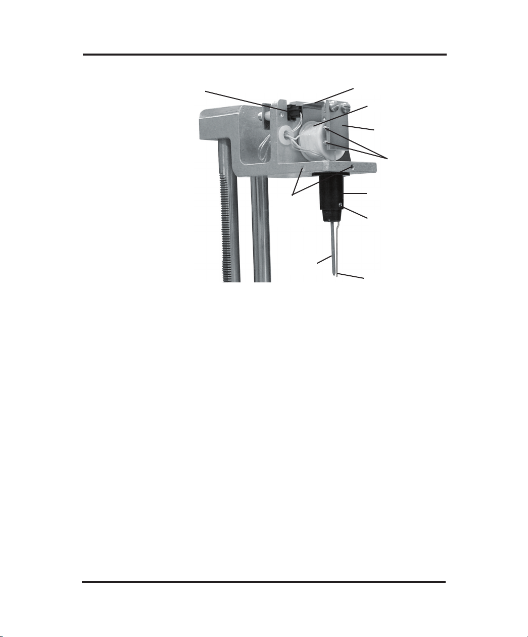
Troubleshooting & Service
Sample Probe
Connector (10)
Mandrel
Setscrews
(9)
Sample
Probe (8)
Yoke (1)
Coil (2)
Clapper (3)
Stir/Freeze
Wire
Setscrews (4)
Mandrel (5)
Sample Probe
Setscrew (6)
Stir/Freeze
Wire (7)
Figure 5: Operating Head
the connector. Use care not to touch or bend the connector pins.
Soil or salt from your fingers can increase the electrical resistance of the connection.
e. With the probe at 25ºC room temperature, the resistance
between the probe leads should be 2000 ohms ±5% and should
be quite sensitive to the warmth of your hand or breath.
With the tip of the probe immersed in a concentrated NaCl solution (do not wet the probe leads or connector in salt water), the
resistance between either probe lead and the solution should be
greater than 20 megohms. Probe damage is indicated by any
deviation from the resistance parameters given above.
If sample probe replacement is indicated:
57
Page 78

The Advanced®Model 3D3 User’s Guide
f. Loosen the two mandrel setscrews (figure 5, item 9). Lower the
probe and mandrel down over the stir wire.
g. Fit a new sample probe by pushing the probe connector and
wires up through the hole in the head chassis before seating the
mandrel. Then raise the mandrel up around the stir wire. Align
the mandrel so the stir-wire channel is perpendicular to the front
edge of the chassis and so the flange is flush, with no gaps
between the flange and the underside of the chassis. Re-tighten
the two setscrews to hold the mandrel in place. Do not over-
tighten, overtightening will damage the mandrel.
h. The probe length is factory set and should not require further
adjustment. Proper positioning of the probe and stir wire can be
quickly confirmed with the probe and stir-wire alignment tool
provided with the instrument, or the method described in section 4.
i. Reconnect the probe connector on the head chassis, taking care
once again not to touch or bend the connecting pins.
j. Arrange the leads so that they will not touch the clapper (figure
5, item 3) or be pinched when the head cover is replaced.
k. Replace the head cover and its two attaching screws.
l. Re-connect the power cord and turn the instrument on.
m. Make sure the Supervisor/Operator keyswitch is in the
Supervisor position (see figure 3 and Chapter 2, Section A.2)
for the following steps.
n. When the operating head rises and “Press START to
Continue” begins to scroll across the display, press the START
switchpad.
58
Page 79

Troubleshooting & Service
o. When the display changes to “Osmometer Ready”, press the
TEST switchpad. The display will change to “Select Test Item”.
p. At “Select Test Item”, repeatedly press the > switchpad until
the display reads “Probe Bin Test”.
q. At “Probe Bin Test”, press START. The display will change
to “[Start] Ready?”.
r. At “[Start] Ready?”, remove the empty sample tube from the
freezing chamber, pipette or measure a sample of probe bin-setting fluid into a clean sample tube, place the tube in the freezing
chamber and press the START switchpad. The 3D3 will run a
special freezing-point test to determine the sample probe resistance and bin number.
NOTE In emergency, H
O may be used in place of bin-setting
2
fluid for this test. The bin number thus determined will
be acceptable for bin setting though the probe resistance
displayed is that at the freezing point of the H
O sam-
2
ple used, and will be different from that for bin-setting
fluid.
s. Record the sample probe resistance and bin number in the ser-
vice log in the back of the user’s guide; then press the STOP
switchpad. The display will change to “Probe Bin Test”.
t. Press SETUP to enter the SETUP menu, then repeatedly press
the > switchpad until the display reads “Set Sample Bin #”.
u. At “Set Sample Bin #”, press the START switchpad. The dis-
play will report the current sample bin number setting.
v. If the current sample bin number setting is not the same as that
just determined, enter the correct bin number by means of the
numeric keypad; then press the ENTER switchpad. The display
59
Page 80

The Advanced®Model 3D3 User’s Guide
will change to “Set Sample Bin #”; then press the STOP switch-
pad to return to “Osmometer Ready”. If the current sample
probe bin setting is the same as that just determined, simply press
the STOP switchpad twice to return to “Osmometer Ready”.
w. Press the CALIB switchpad and calibrate the instrument as
instructed in Chapter 4. Re-calibration is required each time the
sample probe is replaced.
4. Mandrel, probe and stir/freeze wire alignment
Proper alignment and adjustment of the mandrel, probe and
stir/freeze wire are of utmost importance to assure accuracy, precision and proper operation of the instrument.
To facilitate positioning the probe and stir/freeze wire, a probe
alignment tool is included with the instrument and with each
replacement sample probe, along with instructions for its use.
Alternatively, you can cut a used sample tube in half vertically and
use one of the halves to visually align the probe and stir/freeze wire
using the following procedure:
a. Hold one of the tube halves up on the mandrel in the position
shown in figure 6. Rotate the tube half axially around the mandrel, noting in which direction the tip of the probe must be
moved (if any) to perfectly center its black sensor bead in the
center of curvature of the bottom of the tube as shown in figure
6. Remove the sample tube.
b. If vertical adjustment of the probe tip is necessary, to center the
black bead in the 0.2-mL sample volume, loosen the probe
setscrew (figure 5, item 6), then manually raise or lower the
probe within the mandrel. Retighten the setscrew gently (overtightening will crack or distort the thin plastic wall of the mandrel). Recheck as described in step “a” above.
60
Page 81

The flange of the
mandrel must be
flush with the head
chassis.
Troubleshooting & Service
The stir/freeze wire should be
about the width of the
stir/freeze wire away from the
mandrel where it exits from
the mandrel.
The black bead in the
probe tip must be in
the center of a 2-mL
sample in the sample
tube, at equal distances from all nearby
surfaces. It must be
the same distance from
the bottom of the tube
as it is from the side
walls.
The stir/freeze wire should be
about the width of the stir/freeze
wire away from the tip of the
probe. Bend the wire if necessary. The tip of the stir/freeze wire
should be slightly below the bottom of the probe tip. Loosen the
stir/freeze wire setscrews to
enable vertical adjustment.
Figure 6: Mandrel, Probe and Stir/Freeze Wire Adjustment
c. If horizontal adjustment is necessary, to center the black bead in
the sample volume, bend the metal probe stem gently in the
required direction by hand. Recheck as described in step “a”
above.
d. Check and adjust the stir/freeze wire position according to the
recommendations in figure 6.
5. Stir/freeze amplitude adjustment
The stir and freeze vibration amplitudes are affected by the probe,
stir/freeze wire and mandrel positions. If the one-second freeze
pulse is not strong enough to freeze samples reliably, first realign
the stir/freeze wire according to the recommendations in Chapter 5,
Section G.4 and figure 6. Then visually check the freeze and stir
vibration amplitudes as follows:
61
Page 82

The Advanced®Model 3D3 User’s Guide
a. Make sure the Supervisor/Operator keyswitch is in the
Supervisor position while using the TEST and SETUP menus
(see figure 3 and Chapter 2, Section A.2).
b. Press the TEST switchpad. If the Supervisor/Operator
keyswitch is in the Supervisor position, the display will change
to “Select Test Item”.
c. At “Select Test Item”, press the START switchpad. The display
will change to “Test Menu #: 0”.
d. At “Test Menu #: 0”, press the 4 switchpad; then press
ENTER. The display will change to “Stir/Freeze Test”.
e. At “Stir/Freeze Test”, press the START switchpad. The dis-
play will change to “[stir] [freeze]”.
f. At “[stir] [freeze]”, a freeze pulse will occur each time the >
switchpad is pressed. Watch the tip of the stir/freeze wire and
press >. The freeze-pulse vibration should produce a loud
“buzz”. If properly adjusted as recommended in figure 6, the
stir/freeze wire should vibrate principally fore and aft and
should never strike the probe.
Look from the side of the instrument as you press > again; the
freeze-pulse vibration blur at the very tip of the stir/freeze wire
should span at least 0-1/64” or 0-0.5 mm for one second, then
cease.
If the freeze vibration is not enough, first remove the head cover by
removing the top screws and pulling straight up and make sure that
there are absolutely no metal chips between the clapper and the coil
armature. Even a single iron chip will greatly reduce the freeze
amplitude and must be carefully wiped out of the magnetic gap.
Then re-adjust the stir/freeze amplitude as instructed in section 5.
62
Page 83

Troubleshooting & Service
If the freeze vibration is still not enough, readjust the clapper spacing as follows:
g. Refer to figure 5. Bend the yoke (figure 5, item 1) to locate the
clapper (item 3) closer to or further away from the coil (item 2),
whichever is found to increase the stir/freeze wire tip vibration.
Changing the coil-to-clapper spacing probably will adversely
affect the stir/freeze wire tip location; after bending the yoke,
realign the stir/freeze wire according to the recommendations in
figure 6.
Check the freeze vibration amplitudes as instructed in section
5.a-e. Optimum spacing between the coil and clapper should
provide at least 0-1/64” or 0-0.5 mm of tip vibration.
Re-install the operating head cover. Do one last freeze test with
the operating head cover re-installed; the freeze pulse characteristics are slightly different with it in place.
If the freeze vibration is still not enough, do not proceed further
without obtaining Hot-Line service as recommended in Chapter 5,
Section B. If you succeed in obtaining enough freeze vibration, the
stir vibration amplitude must be re-adjusted as follows:
h. Check the stir/freeze wire position according to the recommen-
dations in figure 6. If necessary, remove the two top screws,
remove the head cover and re-adjust the stir/freeze wire position
according to the recommendations in figure 6. Re-install the
head cover.
i. Press the SETUP switchpad.
j. At “Select Setup Item”, press the START switchpad. The dis-
play will change to “Setup Menu #: 0”.
63
Page 84

The Advanced®Model 3D3 User’s Guide
k. At “Setup Menu #: 0”, press the 2 switchpad, then press
ENTER. The display will change to “Set Stir Amplitude”.
l. At “Set Stir Amplitude”, press the START switchpad. The
display will change to “Amplitude = xx”, with “xx” being
some two- or three-digit number around 98.
m. Looking from the side of the instrument, you should be able to
see a stir vibration blur at the tip of the stir/freeze wire. For
0.2-mL to 0.25-mL osmometer operation, the stir vibration blur
at the very tip of the stir/freeze wire should be 0-1/64” or 0-0.5
mm. A very small amount of stirring is necessary to minimize
temperature gradients in viscous samples but more than 1/64”
or 0.5 mm can cause poor repeatability or frothing which may
make it impossible to reliably determine the freezing point.
If the stir vibration amplitude is not correct, press > to increase
the stir amplitude and the “xx” value or press < to decrease the
stir amplitude and the “xx” value. Continue to increase or
decrease the “xx” value as necessary, until the stir vibration blur
at the very tip of the stir/freeze wire is between 0 and 1/64” or
between 0 and 0.5 mm.
As this adjustment is completed, you may wish to hold a sample
tube containing a 0.2-mL sample of either an NaCl standard or
O up in position on the probe and stir/freeze wire to make
H
2
sure that froth is not produced.
n. When the stir amplitude is correct, you may wish to record the
stir-amplitude “xx” value in the Service Log in the back of the
user’s guide for reference. Press ENTER to store the new setting. The display will change to “Set Stir Amplitude”.
o. At “Set Stir Amplitude”, press the STOP switchpad to exit the
SETUP program (or > or < to step to another SETUP item).
64
Page 85

Troubleshooting & Service
p. When STOP is pressed, the display will change to
“Osmometer Ready” and the 3D3 is ready for freezing-point
tests.
65
Page 86

The Advanced®Model 3D3 User’s Guide
Notes:
66
Page 87

Appendix A
Troubleshooting Table
Symptom
Abrupt loss
of power
(no display)
Check
1. Power availability.
Temporarily unplug the
power cord from its wall
outlet and replace it with
a known workable lamp
or small appliance.
2. Power connection.
3. Measure the AC voltage
supplied at the power
outlet used for this
instrument (see Chapter
1, Section A.2).
Compare the measured
voltage with the nominal
voltage indicated beside
the two matching arrowheads on the voltage
selector/fuse holder (see
figure 3).
Suggested Action
a. Have the power
restored.
b. Make sure the power
cord is firmly plugged
into both the wall outlet and the socket on
the back of the instrument.
67
Page 88

The Advanced®Model 3D3 User’s Guide
Symptom
Abrupt loss
of power
(no display)
(continued)
“Block Probe
Failure”
Check
4. Unplug the power cord
from the power cord
socket. Use a small
screwdriver to pry out
the voltage selector/fuse
holder. Visually check
the two 5mm x 20mm
time delay (T) fuses
mounted in it. Use a
continuity checker,
ohmmeter, or replacement fuse to check continuity if there is any
doubt.
Check the values
marked on the fuses.
For 100-130V operation
they should be 2-Amp
fuses; for 200-250V
operation they should
be 1-Amp fuses.
1. Switch the instrument
off, then on.
2. Check the block probe
by running the A/D Test
(see Chapter 5, Section
F.1).
Suggested Action
c. Replace the fuses if
blown or of incorrect
value.
d. Re-install the fuse
holder into the back of
the instrument with the
correct arrowheads
matching.
e. If the fuses were blown
and the replacement
fuses blow also, see
Chapter 5, Section B
for further assistance.
a. If the error message
does not persist and
other error messages are
not displayed, ignore
this message.
b. If the error message
persists, see Chapter 5,
Section B for further
assistance.
“Calibration
Out of Range;
Repeat Calib”
68
Procedure, technique (poor
repeatability; see Chapter 2,
Section G and Repeatability
Tips).
Recalibrate (see Chapter
4).
Page 89

Troubleshooting Table
Symptom
“Cooling
System Error”
“EPROM
Failure”
“Event
Record Lost”
“Fan Driver
Failure”
Check
1. Switch the instrument
off, then on.
2. Check that heat transfer
fluid is present in the
freezing chamber.
Switch the instrument off,
then on.
Switch the instrument off,
then on.
Switch the instrument off,
then on.
Suggested Action
a. Retry the test.
b. Make sure the heat trans-
fer fluid is properly
installed and primed (see
Chapter 1, Sections C
and D.4).
c. If the error message per-
sists, see Chapter 5,
Section B for further
assistance.
If the error message persists, see Chapter 5, Section
B for further assistance.
If the error message persists, see Chapter 5, Section
B for further assistance.
a. Retry the test.
b. If the error message per-
sists, see Chapter 5,
Section B for further
assistance.
“Head Not
Up” or
“Head Not
Down”
1. Switch the instrument
off, then on.
2. Check the alignment by
running the Head
Up/Down Test (see
Chapter 5, Section F.8).
a. If the error message
persists, see Chapter 5,
Section B for further
assistance.
69
Page 90

The Advanced®Model 3D3 User’s Guide
Symptom
“Illegal Error
Code”
“No Plateau,
Repeat Test”
No response
when the
START or
TEST
switchpad is
pressed
Check
Switch the instrument off,
then on.
Switch the instrument off,
then on.
Suggested Action
a. Retry the test.
b. If the error message
persists, see Chapter 5,
Section B for further
assistance.
a. Prepare another sample
and repeat the test (see
Chapter 2, Section G
and Repeatability Tips).
b. If the error message
persists, see Chapter 5,
Section B for further
assistance.
If the problem persists, see
Chapter 5, Section B for
further assistance.
“Parameter
RAM Failed”
or “New
Software
Version”
70
a. If followed by “Reset
Probe Configuration,”
see Symptom item
“‘Reset Probe
Configuration’ displayed during the
power-up sequence”.
b. If not followed by
“Select Test Item”, see
Chapter 5, Section B
for further assistance.
Page 91

Troubleshooting Table
Symptom
“RAM
Failure”
“Re-calibration Needed”
“Reset Probe
Configuration”
displayed
during the
power-up
sequence
Results not
repeatable
(too scattered)
Check
Switch the instrument off,
then on.
Calibrate the instrument
(see Chapter 4).
1. Operator procedures
and technique.
2. Check the sample probe
by running the A/D Test
(Chapter 5, Section
F.1).
Suggested Action
If the error message persists, see Chapter 5, Section
B for further assistance.
If the error message
repeats after successful recalibration, see Chapter 5,
Section B for further assistance.
a. If followed by “Reset
Probe Configuration”,
see Symptom item
“Select Test Item”.
b. If not followed by
“Select Test Item”, see
Chapter 5, Section B
for further assistance.
a. See Chapter 2, Section
G and Repeatability
Tips.
b. Replace the sample
probe (see Chapter 5,
Section G.3).
c. If the error message
persists, see Chapter 5,
Section B for further
assistance.
71
Page 92

The Advanced®Model 3D3 User’s Guide
Symptom
“Sample Did
Not Freeze,
Repeat Test”
Check
Freeze “buzz” occurred
1. Was the sample tube
left empty?
2. Is the freezing point of
the sample beyond the
range of the instrument
(see Appendix B)?
3. Does the sample contain many small bubbles
or froth?
4. Is the sample very viscous?
Suggested Action
Freeze “buzz” occurred
a. Prepare another sample
and repeat the test (see
Chapter 2, Section G
and Repeatability Tips).
b. Try testing samples
known to be within the
range of the instrument.
c. Make sure the samples
contain no bubbles or
froth before testing.
d. Decrease the sample stir
amplitude, if necessary,
to avoid generating
bubbles before the
freeze buzz occurs (see
Chapter 5, Section G.5).
e. The 3D3 is not
designed to test thick or
very viscous samples.
72
5. Is the probe configuration correct?
f. Check/correct the probe
bin #’s (see Chapter 2,
Section G and
Repeatability Tips).
Page 93

Troubleshooting Table
Symptom
“Sample Did
Not Freeze,
Repeat Test”
(continued)
Check
Poor or no freeze “buzz”
1. Check for debris in the
magnetic gap between
the clapper and coil (see
figure 5).
2. The stir/freeze wire
must be firmly held in
the clapper by both
mounting screws (see
figure 5).
3. Check the stir/freeze
wire alignment (see figure 6).
4. Check the stir/freeze
amplitude (see Chapter
5, Section G.5).
5. The stir wire may be
fatigued (too ductile).
Suggested Action
Poor or no freeze “buzz”
a. Prepare another sample
and repeat the test (see
Chapter 2, Section G
and Repeatability Tips).
b. Clean all debris from
the magnetic gap.
c. Tighten both stir/freeze
mounting screws firmly
(see figure 5).
d. Correct the stir/freeze
wire alignment as necessary (see figure 6).
e. Replace, align and
adjust the stir/freeze
wire (see Chapter 5,
Sections G.4 and G.5
and figure 6).
f. If the error message
persists, see Chapter 5,
Section B for further
assistance.
73
Page 94

The Advanced®Model 3D3 User’s Guide
Symptom
“Sample
Freeze Error;
Repeat Test”
“Result = 0,
Calibration
Okay?”
“Sample
Probe
Failure”
Check
1. Was the sample volume
correct?
2. Is the block probe bin #
correct?
3. Check the alignment by
running the Head
Up/Down Test (Chapter
5, Section F.8).
Check the calibration
(unless running a 0 mOsm
sample).
1. Switch the instrument
off, then on.
2. Check the sample probe
by running the A/D Test
(see Chapter 5, Section
F.1).
Suggested Action
a. Prepare another sample
and repeat the test (see
Chapter 2, Section G
and Repeatability Tips).
b. Check/correct the block
probe bin # (see
Chapter 5, Section F.3).
c. If the error message
persists, see Chapter 5,
Section B for further
assistance.
Recalibrate (see Chapter
4) unless running a 0
mOsm sample.
a. If the error message
does not persist and
other error messages are
not displayed, ignore
this message.
b. Replace the sample
probe (see Chapter 5,
Section G.3).
74
Page 95

Troubleshooting Table
Symptom
“Sample
Pre-Freeze;
Repeat Test”
Check
1. Were the sample probe
and tube clean?
2. Is the probe configuration correct?
3. Check the stir/freeze
wire alignment and
adjustment (see Chapter
5, Sections G.4 and G.5
and figure 6).
4. Particulate matter tends
to cause premature
crystallization.
Suggested Action
a. Prepare another sample
and repeat the test (see
Chapter 2, Section G
and Repeatability Tips).
b. Check/correct the block
probe bin # (see Chapter
5, Section F.3).
c. Correct the stir/freeze
wire alignment and
adjustment as necessary
(see Chapter 5, Sections
G.4 and G.5 and figure
6).
d. Try to minimize the
effects of materials that
tend to cause premature
crystallization.
e. If the error message per-
sists, see Chapter 5,
Section B for further
assistance.
“Standards
Reversed?
Repeat Calib”
“Stir/Freeze
Failure”
Did you introduce the
right calibration standards
in the right order?
Switch the instrument off,
then on.
Recalibrate with the correct calibration standards
(see Chapter 4).
a. Retry the test.
b. If the error message
persists, see Chapter 5,
Section B for further
assistance.
75
Page 96

The Advanced®Model 3D3 User’s Guide
Symptom
“Select
Test Item”
“Supervisor
Key Needed;
Press STOP”
Check
Check the KEYSWITCH
position.
Suggested Action
a. Press > to advance to
“Set Block Probe Bin
#” in the SETUP menu
and reset the block
probe bin # (see
Chapter 2, Section C.1).
b. Press > to advance to
“Set Sample Probe Bin
#” in the SETUP menu
and reset the sample
probe in # (see Chapter
2, Section C.2).
c. Reset the stir amplitude,
as necessary, to the
number recorded in the
service log in the back
of the user’s guide.
Place the KEYSWITCH
in the SUPERVISOR
position before attempting
to use CALIB or TEST.
“Thermoelectrics
Driver
Failure”
76
Switch the instrument off,
then on.
a. Retry the test.
b. If the error message
persists, see Chapter 5,
Section B for further
assistance.
Page 97

Troubleshooting Table
Symptom
“System Error:
Requests”
“System Error:
Primitive”
“System Error:
Intercept”
“System Error:
Communications”
“System Error:
Unknown”
“System Error:
Trap”
System Error:
NMI”
“Sample
Probe
Open?”
Check
Switch the instrument
off, then on.
1. Switch the instrument
off, then on.
2. Check the sample
probe by running the
A/D Test (see Chapter
5, Section F.1).
Suggested Action
If the error message persists, see Chapter 5,
Section B for further
assistance.
a. If the error message
does not persist and
other error messages are
not displayed, ignore
this message.
b. Replace the sample
probe (see Chapter 5,
Section G.3).
77
Page 98

The Advanced®Model 3D3 User’s Guide
Symptom
“Test
Time-out
Error”
Check
1. Was the sample OK?
2. Does the freezing
chamber contain heat
transfer fluid?
3. Is the block probe bin #
correct?
4. Check the alignment by
running the Head
Up/Down Test (see
Chapter 5, Section F.8).
Suggested Action
a. Prepare another sample
and repeat the test (see
Chapter 2, Section G
and Repeatability Tips).
b. Check the heat transfer
fluid (see Chapter 2,
Section B). Replace
and prime as necessary
(see Chapter 1, Section
C).
c. Check/correct the block
probe bin # (see
Chapter 5, Section F.3).
d. If the error message
persists, see Chapter 5,
Section B for further
assistance.
78
Page 99

Appendix B
Product Specifications
Electrical:
Power Requirement: 100 to 130 VAC (60 Hz) or 200 to 250 VAC (50 Hz)
Fuses (2): 250V time delay (Type T): 2-Amp (100-130 VAC),
1-Amp (200-250 VAC)
Power Consumption: 150 Watts
Memory Backup: Integral lithium cell; 10 years typical
Sample Volume: 0.20 to 0.25 mL
Sample Capacity: Single sample
Readout: 20-character digital display
Units: mOsm/kg H
Range:
Low: 0 to 2000 mOsm/kg H
High: 1400 to 4000 mOsm/kg H
Linearity: Less than ±0.5% from straight line
Resolution: 1 mOsm/kg H2O
Repeatability: 0 to 400 mOsm ±2 mOsm/kg (1 S.D.)
400 to 4000 mOsm ±0.5% (1 S.D.)
Communications: DTE RS-232C, parallel printer, barcode
Storage
Temperature: -40 to +45°C (-40 to +113°F)
Operating Temp.
(ambient): 18 to 35°C (64 to 95°F)
O
2
O
2
O
2
79
Page 100

The Advanced®Model 3D3 User’s Guide
Drift:
Ambient Temperature Effect:
Room Humidity:
Startup Time:
Test Time:
Dimensions:
Width:
Depth:
Height:
With Head Up:
Weight:
Net:
Shipping:
Warranty:
Less than 1 digit per month
1 digit for every 5°C (9°F) ambient temperature change
5 to 80% R.H. (non-condensing)
From Stand-By: immediately
From Power On: under 5 minutes .
Approximately 2 minutes per sample in 0 to 2000 mOsm
range; moderately longer in high range.
inches centimeters
12.5 32
16.5 42
11.5 29
16 41
pounds kilograms
27 12
38 18
One-year limited warranty on workmanship and all parts
except glass, plastic, and parts warranted by their makers.
Certification:
80
 Loading...