

Page 1
Advanced
Advanced
®
Osmometer Model 3250
®
Cryoscope Model 4250
Service Manual
3255SM Rev22 020416
Page 2

Page 3

Table of Contents
1. Introduction
Specifications . . . . . . . . . . . . . . . . . . . . .7
General Description and Purpose . . . .11
Service Assistance . . . . . . . . . . . . . . . .11
Safety/Regulatory Information . . . . . .12
Symbol Conventions . . . . . . . . . . . . . .12
General Cautions . . . . . . . . . . . . . . . . .12
Service & Maintenance Cautions . . . .13
Hazardous Material Cautions . . . . . . .14
Regulatory Notices . . . . . . . . . . . . . . .14
Symbol Conventions . . . . . . . . . . . . . .14
FCC Requirements . . . . . . . . . . . . . . .15
2. General Overview
General Overview . . . . . . . . . . . . . . . .21
Calibration . . . . . . . . . . . . . . . . . . . . . .23
Circuit Description . . . . . . . . . . . . . . .24
Power Supply . . . . . . . . . . . . . . . . . . . .24
Front End . . . . . . . . . . . . . . . . . . . . . . .24
325605 Control Board Set . . . . . . . . . .24
325620/425620/325621/425621
Processor Board . . . . . . . . . . . . . . . .25
PCB605 Application Board . . . . . . . . .26
Other Circuit Components . . . . . . . . . .27
Design Changes . . . . . . . . . . . . . . . . . .29
Replacement Parts . . . . . . . . . . . . . . . .30
Supplies & Accessories . . . . . . . . . . . .32
3. Maintenance
Cleaning and Maintenance . . . . . . . . .35
Removing the Head & Instrument
Covers . . . . . . . . . . . . . . . . . . . . . . .36
Osmometer/Cryoscope Well Cleaning 37
Cleaning and Lubricating the Printer .39
Probe & Stir/Freeze Wire Alignment .40
4. Troubleshooting
Introduction . . . . . . . . . . . . . . . . . . . . .43
Freeze “Buzz” Amplitude . . . . . . . . . .44
Stir Driver Noise . . . . . . . . . . . . . . . . .45
Head Sensor Adjustment . . . . . . . . . . .47
Head Up/Down Test . . . . . . . . . . . . . .48
Power On Diagnostics . . . . . . . . . . . . .49
A/D Tests . . . . . . . . . . . . . . . . . . . . . . .49
Sample Bin Setting . . . . . . . . . . . . . . .50
Block Bin Setting . . . . . . . . . . . . . . . .51
Stir Amplitude . . . . . . . . . . . . . . . . . .51
Display/Printer Test . . . . . . . . . . . . . . .51
Beeper Test . . . . . . . . . . . . . . . . . . . . .52
Keypad Test . . . . . . . . . . . . . . . . . . . . .52
Barcode Test . . . . . . . . . . . . . . . . . . . .52
Reset Serial Number . . . . . . . . . . . . . .52
Instrument Software Updates . . . . . . .54
Performing FLASH firmware update .54
Troubleshooting Table . . . . . . . . . . . . .56
5. Replacement Instructions
Block Probe (4D3340) . . . . . . .325P340
Clapper (3C2241R) . . . . . . . .3C2P241R
Control Board Set (325605R/425605R),
Application Board (PCB605R),
Processor Board (325621R/
425621R) . . . . . . . . . . . . . .325P620
Cooling Assembly (3D3300R/
4D3300R) . . . . . . . . . . . .325P300
Cooling Fan (4D3360) . . . . . . .325P360
Display Board (74051R/
702041R) . . . . . . . . . . . .325P051
Driver Board (PCB523R) . . .PCB523PM
Fuse (70011/70022) . . . . . . . . . . .325P11
Head Up Relay or Head Down
Relay (3D3109) . . . . . . . . . .325P109
Heat Transfer Fluid Pump
Assembly (4D3690), Fluid
Filter (4D3710R), One-way Check
Valve (4D3705R/99133R) . . . .4DP690
Keypad (325511R) . . . . . . . . . .325P511
Load Resistor (425150R) . . . . .42P150R
Mandrel (3LH500) . . . . . . . . . .3LHP500
Motor Assembly (4D3350R/
325304R) . . . . . . . . . . . . . .325P350
NVRAM Battery (71027R) . . . .71P27R
Power Supply Assembly (4D3950/
325950R) . . . . . . . . . . . . . .325P950
Printer Assembly (325400R) . . .325P401
Printer Assembly (325420R) .325420PM
Printer Mechanism
(325404R) . . . . . . . . . . . . . .325404PM
Probe Alignment Tool Kit
(3LA700) . . . . . . . . . . . . . . . . .3LP700
Sample Probe (3D3700) . . . . . . .3DP700
Sample Probe (3D3700) . . . . . .325P700
Sample Probe (4D3102) . . . . . . .4D3P02
Cryoscope Sample Probe
Versions FAQ . . . . . . . . . . . . .4DP002
Stir/Freeze Coil (3D2404R) . . .325P404
3
The Advanced®Model 3250/4250 Service Manual
Page 4

Stir/Freeze Wire (3LH243/
4LH243) . . . . . . . . . . . . . . . .4LHP243
Transistor (PCB520R) . . . . . . .PCP520R
Transistor (PCB522R) . . . . . . .PCP522R
Tube Ejector Spring (3D3312R/
4D3312) . . . . . . . . . . . . . . . 4DP312
Upgrade Kit, 3250/4250 Suffix
D to E (325024) . . . . . . . . .325025PM
Yoke (3LH230R) . . . . . . . . . . .3LHP230
6. Schematics
PCB402 Assembly Drawing
PCB402 Printer Interface Board
Schematic
PCB402 Schematic
PCB523 Assembly Drawing
PCB523 Driver Board Schematic
PCB523 Schematic
PCB605 Assembly Drawing
PCB605 Application Board Schematic
PCB605 Schematic
PCB620 Assembly Drawing
PCB620 Processor Board Schematic
210102 Assembly Drawing
210102 Schematic
3D3380 Assembly Drawing
3D3380 Schematic
325000 Interconnection Schematic
APPENDICES
A: Symbol Definitions
B: Product Disposal and Recycling
C: Service Log
Index
The Advanced®Model 3250/4250 Service Manual
4
Page 5

1. Introduction
Page 6

Page 7

Model 3250 Osmometer Specifications
Applies to Serial Suffix A - C. Refer to Design Changes for more information.
Electrical:
Voltage: 100 to 130 VAC (1.2 A) or 200 to 250
VAC (0.6 A)
Frequency: 50 or 60 Hz
Fuses: 2-Amp time delay for 100-130 VAC;
1-Amp time delay for 200-250 VAC
Power: 150 Watts
Memory Backup: integral lithium cell; 10 years
min. (not user-replaceable)
Sample Volume: 0.2 or .25 mL
Sample Capacity: single sample
Readout: 20-character digital display
Units: mOsm/Kg H2O
Range:
Low: 0 to 2000 mOsm/Kg H2O
High: 1400 to 4000 mOsm/Kg H2O
Resolution: 1 mOsm/Kg H2O
Performance Over Operating Conditions
Temperature Effects: Less than 1 mOsm/Kg H
for every 5°C (9°F) ambient
temperature change.
Operating Conditions
Temperature: 18°C to 35°C (64°F to 95°F)
Room Humidity: 5 to 80% relative humidity;
(non-condensing)
Storage Temperature: -40°C to +45°C
(-40°F to +113°F)
Start-up Time: From stand-by: immediately
From power on: under 5 minutes
Test Time: Approximately 2 minutes per sample
in 0 to 2000 mOsm range; moderately
longer in high range.
Dimensions inches centimeters
Width: 13 32
Depth: 18 46
Height: 16 41
O
2
Communications:
RS-232C and barcode scanner ports
Weight pounds kilograms
Net: 28 13
Shipping: 39 19
Performance at Reference Conditions
1
Warranty: One-year limited warranty on work-
Linearity: Less than ±0.5% from a straight line
manship and all parts except glass,
plastic and parts warranted by their
Repeatability:
makers.
0 to 400 mOsm ±2 mOsm/Kg (1 S.D.)
400 to 4000 mOsm ±0.5% (1 S.D.)
Drift: Less than 1 mOsm/Kg H
O per
2
Certification:
month
Refer to Regulatory Notices (see page 14) for applicable standards.
Installation Class: I
Over-Voltage Category: II
Pollution Degree: 2
Moisture Protection: IPX0 (Ordinary)
1
Reference Conditions: 20 to 25°C (68 to 77°F); 40 to 60% Relative Humidity; tolerances of reference or calibration solutions
excluded.
7
The Advanced®Model 3250/4250 Service Manual
Page 8

Model 3250 Osmometer Specifications
Applies to Serial Suffix D and Higher. Refer to Design Changes for more information.
Electrical:
Voltage: 100 to 250 VAC (0.6 A)
Frequency: 50 or 60 Hz
Fuses: 2-Amp time delay (Type T)
Power: 95 Watts
Memory Backup: integral lithium cell; 10 years
min. (not user-replaceable)
Sample Volume: 0.2 or .25 mL
Sample Capacity: single sample
Readout: 20-character digital display
Units: mOsm/Kg H2O
Range:
Low: 0 to 2000 mOsm/Kg H2O
High: 1400 to 4000 mOsm/Kg H2O
Resolution: 1 mOsm/Kg H2O
Communications:
RS-232C and barcode scanner ports
Performance at Reference Conditions
1
Linearity: Less than ±0.5% from a straight line
Repeatability:
0 to 400 mOsm: Std. Deviation < 2 mOsm/Kg H2O
400 to 4000 mOsm: Std. Deviation < 0.5% of value
mOsm/Kg H2O
Drift: Less than 1 mOsm/Kg H
O per
2
month
Performance Over Operating Conditions
Temperature Effects: Less than 1 mOsm/Kg H
2
for every 5°C (9°F) ambient
temperature change.
Operating Conditions
Temperature: 18°C to 35°C (64°F to 95°F)
Room Humidity: 5 to 80% relative humidity;
(non-condensing)
Storage Temperature: -40°C to +45°C
(-40°F to +113°F)
Start-up Time: From stand-by: immediately
From power on: under 5 minutes
Test Time: Approximately 2 minutes per sample
in 0 to 2000 mOsm range; moderately
longer in high range.
Dimensions inches centimeters
Width: 13 32
Depth: 18 46
Height: 16 41
Weight pounds kilograms
Net: 23 10
Shipping: 34 15
Warranty: One-year limited warranty on work-
manship and all parts except glass,
plastic and parts warranted by their
makers.
Certification:
O
Refer to Regulatory Notices (see page 14) for applicable standards.
Installation Class: I
Over-Voltage Category: II
Pollution Degree: 2
Moisture Protection: IPX0 (Ordinary)
1
Reference Conditions: 20 to 25°C (68 to 77°F); 40 to 60% Relative Humidity; tolerances of reference or calibration solutions
excluded.
The Advanced®Model 3250/4250 Service Manual
8
Page 9

Model 4250 Cryoscope Specifications
Applies to Serial Suffix A - C. Refer to Design Changes for more information.
Electrical:
Voltage: 100 to 130 VAC (1.2 A) or 200 to 250
VAC (0.6 A)
Frequency: 50 or 60 Hz
Fuses: 250V time delay (Type T):
2-Amp time delay for 100-130 VAC;
1-Amp time delay for 200-250 VAC
Power: 150 Watts
Memory Backup: integral lithium cell; 10-year
life (typical); (not userreplaceable)
Sample Volume: 2.0 to 2.5 mL
Sample Capacity: single sample
Readout: 20-character vacuum fluorescent
display
Units: mºC or mºH
Range: 0 to 1000 mºC or mºH
Resolution: 1 mºC or mºH
Communications: On-board printer, DTE EIA-
232/V.24 (RS-232) serial port
and optional barcode scanner
Performance at Reference Conditions
Linearity: Less than ±0.5% from a straight line
1
Performance Over Operating Conditions
Temperature Effects: Less than 1 unit for every
5°C (9°F) ambient tempera
ture change.
Operating Conditions
Temperature: 18°C to 35°C (64°F to 95°F)
Room Humidity: 5 to 80% relative humidity;
(non-condensing)
Storage Temperature: -40°C to +45°C
(-40°F to +113°F)
Start-up Time: From stand-by: immediately
From power on: under 5 minutes
Test Time: Approximately 90 seconds in 30-
second timed mode.
Dimensions inches centimeters
Width: 13.0 33.0
Depth: 18.0 45.7
Height: 12.0 30.5
with Head Up: 16.0 40.6
Weight pounds kilograms
Net: 28.0 12.7
Shipping: 39.0 17.7
Warranty: One-year limited warranty on work-
manship and all parts except glass,
plastic and parts warranted by their
makers.
Repeatability:
± 2 mºC or mºH (1 S.D.) between 0 and -400 mºC
± 0.5% (1 S.D.) between -400 and -1000 mºC
Drift: Less than 1 unit per month
Certification:
Refer to Regulatory Notices (see page 14) for applicable standards.
Installation Class: I
Over-Voltage Category: II
Pollution Degree: 2
Moisture Protection: IPX0 (ordinary)
9
The Advanced®Model 3250/4250 Service Manual
Page 10

Model 4250 Cryoscope Specifications
Applies to Serial Suffix D and Higher. Refer to Design Changes for more information.
Electrical:
Voltage: 100 to 250 VAC (0.6 A)
Frequency: 50 or 60 Hz
Fuses: 2-Amp time delay (Type T)
Power: 95 Watts
Memory Backup: integral lithium cell; 10-year
life (typical); (not userreplaceable)
Sample Volume: 2.0 to 2.5 mL
Sample Capacity: single sample
Readout: 20-character vacuum fluorescent
display
Units: mºC or mºH
Range: 0 to 1000 mºC or mºH
Resolution: 1 mºC or mºH
Communications: On-board printer, DTE EIA-
232/V.24 (RS-232) serial port
and optional barcode scanner
Performance at Reference Conditions
1
Performance Over Operating Conditions
Temperature Effects: Less than 1 unit for every
5°C (9°F) ambient tempera
ture change.
Operating Conditions
Temperature: 18°C to 35°C (64°F to 95°F)
Room Humidity: 5 to 80% relative humidity;
(non-condensing)
Storage Temperature: -40°C to +45°C
(-40°F to +113°F)
Start-up Time: From stand-by: immediately
From power on: under 5 minutes
Test Time: Approximately 90 seconds in 30-
second timed mode.
Dimensions inches centimeters
Width: 13.0 33.0
Depth: 18.0 45.7
Height: 12.0 30.5
with Head Up: 16.0 40.6
Weight pounds kilograms
Net: 23 10
Shipping: 34 15
Linearity: Less than ±0.5% from a straight line
Repeatability:
0 to -400 mºC: Std. Deviation <
-400 to -1000 mºC: Std. Deviation < 0.5% of value
mºC or mºH
Drift: Less than 1 unit per month
The Advanced®Model 3250/4250 Service Manual
2 mºC or mºH
Warranty: One-year limited warranty on work-
manship and all parts except glass,
plastic and parts warranted by their
makers.
Certification:
Refer to Regulatory Notices (see page 14) for applicable standards.
Installation Class: I
Over-Voltage Category: II
Pollution Degree: 2
Moisture Protection: IPX0 (ordinary)
10
Page 11

General Description and Purpose
Service Assistance
®
Advanced
Osmometers and Cryoscopes
determine the concentration of solutions
through freezing-point depression measurement. Osmometers are used primarily to
measure body fluids such as serum and urine,
and cryoscopes are used to determine the
freezing points of various liquids and to
detect added water in milk. Application information is available upon request.
Except for different cooling assemblies,
stir/freeze wires, sample sizes and software,
the 3250 and the 4250 are identical to one
another. For clarity when replacing parts or
troubleshooting, the instructions indicate any
significant differences between the two instruments.
The Service Manual
This Service Manual contains:
To contact Advanced Instruments Product
Service:
• Call (800) 225-4034 (toll-free within the
USA and Canada; after normal business
hours, dial extension 2191)
• Call +US (781) 320-9000 (elsewhere)
• Or fax (781) 320-3669
When calling Advanced Instruments, have the
model and serial number from the label on the
back of the instrument, and a description of
the problem. Use a telephone as close to the
instrument as possible in order to facilitate
making recommended diagnostic checks.
A service technician may assist in making
minor repairs over the phone, providing you
with recommended parts (or part numbers), or
may issue an authorization (RMA) to ship the
instrument for factory repair.
• instructions for performing repairs.
• guides for troubleshooting operational and
mechanical problems.
• circuit system illustrations.
• information about replacement parts and
service repairs.
This manual is designed to assist
service technicians, and does not
imply a license to perform repairs
without proper qualifications.
The RMA procedure is as follows:
1. Contact Advanced Instruments to obtain
an RMA.
2. Pack and ship the instrument in its original carton. Do not send instrument supply items.
3. Prepay shipment to the factory. Advanced
Instruments cannot accept collect ship-
ments. Insure the shipment or accept the
damage risk.
11
The Advanced®Model 3250/4250 Service Manual
Page 12
Safety / Regulatory Information
To reduce the risk of bodily injury,
electric shock, fire, and damage to
your instrument, please read and
observe the following precautions.
• If the product is used in a manner not in
accordance with the equipment design,
operating instructions or manufacturer's
recommendations, the operation of the
product may be impaired to the extent that
a safety hazard is created.
• Do not attempt to perform electrical work
if you are not fully qualified. This manual
is not a substitute for electrical training.
Symbol Conventions
The exclamation point within an
equilateral triangle is intended to
alert the user to the presence of
important operating and maintenance
(servicing) instructions in the literature accompanying this product.
The lightning flash with arrowhead
symbol within an equilateral triangle
is intended to alert the user to the
presence of uninsulated dangerous
voltage within the product's enclosure that may be of sufficient magnitude to constitute risk of electric
shock to persons.
The static symbol within an equilateral triangle is intended to alert the
user to the presence of internal components that could be damaged by
static electricity.
This symbol indicates the presence
of a fuse.
This symbol indicates the presence
of protective earth ground.
This symbol indicates the power is
ON.
This symbol indicates the power is
OFF.
NOTE Additional symbol definitions are
available in the Symbols section.
General Cautions
• This product should be operated only with
the type of power source indicated on the
product’s electrical ratings label. Refer to
the installation instructions included with
the product.
• If the power cord provided is replaced for
any reason or if an alternate cord is used,
the cord must be approved for use in the
local country. The power cord must be
approved for the product’s listed operating
voltage and be rated at least 20% greater
than the ampere ratings marked on the
product’s electrical ratings label. The cord
end that connects to the product must have
an IEC 60320 connector.
• Plug the product into an approved grounded electrical outlet.
This static symbol is intended to
alert the user to the presence of a
specific component that could be
damaged by static electricity.
This symbol indicates the presence
of alternating current (AC).
The Advanced®Model 3250/4250 Service Manual
• Do not disable the power cord’s grounding
plug.
• If an extension cord or power strip is used,
make sure that the cord or strip is rated for
the product, and that the total ampere ratings of all products plugged into the extension cord or strip do not exceed 80% of the
cord’s or strip’s rating limit.
12
Page 13

• Route power cords so that they will not be
walked on, tripped on, or pinched by items
placed upon or against them. Pay particular attention to the plug, electrical outlet,
and the point where the cord exits the
product.
• Do not pull on cords and cables. When
unplugging cords or cables, grasp the corresponding connector.
• Do not install or use this product in any
area subject to extreme short-term temperature variations, or locations that exceed
the specified operating environment temperatures.
• Never use this product in a wet area.
- The power cord, extension cord, power
strip or power input module is damaged.
- Liquid has been spilled into the interior
of the product.
- A foreign object has fallen into the
product.
- The product has been dropped or damaged by a falling object.
- There are noticeable signs of overheating or a burning odor.
- The product does not operate normally
when you follow the operating procedures.
• To avoid injury or fire hazard, do not operate this product in an explosive atmosphere.
• Do not install or use the product on an
unstable, non-level work surface.
• Do not operate this product with the covers
removed or unsecured.
Service & Maintenance Cautions
• Unplug the power cord prior to opening or
removing covers, or else you may be
exposed to electric shock, excessive temperatures, or mechanical hazards.
• Performing service or maintenance not
detailed in the User’s Guide, with or without this Service Manual, should only be
done by a qualified service technician.
• Never restrict airflow into or out of the
product. Occasionally, check the air vents
for blockage.
• Wipe the exterior of the product with a
soft, damp cloth as needed. Using cleaning
products other than those specified, may
discolor or damage the finish.
• If the product requires service for any of
the following reasons, unplug the product
from the electrical outlet and refer service
to a qualified service technician.
- The main supply fuse(s) or any internal
fuse(s) continually fail.
• A discharge of static electricity from contact with the human body or other conductor may damage system boards or static
sensitive devices. Never perform internal
maintenance without following recommended static protection procedures.
• The product is equipped with operator
accessible fuses. If a fuse blows, it may be
due to a power surge or failure of a component. Replace the fuse only once. If the
fuse blows a second time, it is probably
caused by failure of a component part. If
this occurs, refer service to qualified service personnel. Always replace the fuse
with one of the same rating, voltage, and
type. Never replace the fuse with one of a
higher current rating.
• When servicing the product, use only factory-specified parts.
• WARNING: When returning this product
for service, or shipping this product to a
second location, remove all hazardous
specimens and decontaminate the product
before packaging for shipment. If the
product cannot be decontaminated, consult
with your shipping agent on appropriate
packaging and marking.
13
The Advanced®Model 3250/4250 Service Manual
Page 14

Hazardous Material Cautions
• WARNING: Handle all biohazardous
materials according to established good
laboratory practices and follow your institution’s exposure control plan. Persons
handling human blood and body fluid
samples must be trained in blood-borne
hazards and observe universal precautions.
Universal precautions is an approach to
infection control, where all human blood
and body fluids are treated as if known to
be infectious. Use personal protective
equipment such as gloves, gowns, etc., to
prevent exposure. Store biohazardous
materials in regulated waste containers and
dispose of these materials in a safe and
acceptable manner that is in compliance
with all country, state and local requirements.
• If a biohazardous material is spilled on or
inside the equipment, decontaminate the
equipment using a 1% bleach solution, or
as outlined by those policies and procedures established within your institution.
• To avoid injury or fire hazard, do not operate this product in an explosive atmosphere.
Regulatory Notices
• This product has been designed and manu-
factured in accordance with U.S.,
Canadian, and European regulatory
requirements as outlined below.
Modifications made to this product that are
not expressly approved in writing by the
manufacturer will void the user’s authority
to operate this product, previously issued
factory approvals, and the user’s rights
under the warranty.
• The distributor or dealer may have applied
additional local, national, or international
approvals to this product. Consult the distributor or dealer for more information and
documentation.
• Connections to this product must be made
with shielded cables. Use of non-shielded
cables may violate RFI/EMI limits.
Symbol Conventions
This symbol indicates conformity to
relevant European directives.
This symbol indicates the product
was tested to conform to relevant
Canadian and U.S. safety standards
by Intertek Testing Services NA,
Inc. The ETL mark is approved in
the United States as a Nationally
Recognized Testing Lab (NRTL) by
OSHA, and in Canada by the
Standards Council of Canada.
In Vitro Diagnostic Medical Device
complying with EU Directive
98/79/EC.
This symbol, depending upon its
location, indicates the assembly,
component, and/or product are free
of lead. In respect to its inclusion
on a circuit component or assembly,
the following must be adhered to
when servicing. Failure to do so
may result in defects caused by dissimilar metals.
1. Do not repair or modify using a
lead-containing solder.
2. Do not repair or modify using any
soldering tools that have been in
contact with lead-containing solders.
3. Do not repair or modify with any
lead-free solder other than that
specified by the manufacturer or
as indicated by the symbology of
standard IPC-1066.
4. Do not repair or modify using any
soldering tools that have been in
contact with any other incompatible lead-free solders.
5. Contact factory service for further
information.
The Advanced®Model 3250/4250 Service Manual
14
Page 15

The number in this symbol indicates
the type of lead-free solder used in
the assembly of printed circuit
boards, per standard IPC-1066.
Repair or modification must be per-
XAMPLES
E
ONLY
formed using the same or compatible
type lead-free solder and matching
tools. Failure to do so may result in
defects caused by dissimilar metals.
Contact factory service for further
information.
FCC Requirements
• WARNING: Changes or modifications to
this unit not expressly approved by
Advanced Instruments could void the
user’s authority to operate the equipment.
• This equipment has been tested and found
to comply with the limits for a Class B
digital device, pursuant to Part 15 of the
FCC Rules. These limits are designed to
provide reasonable protection against
harmful interference in a residential installation. This equipment generates, uses,
and can radiate radio frequency energy
and, if not installed and used in accordance with the instructions, may cause
harmful interference to radio communications. However, there is no guarantee that
interference will not occur in a particular
installation. If this equipment does cause
harmful interference to radio or television
reception, which can be determined by
turning the equipment off and on, the user
is encouraged to try to correct the interference by one or more of the following
measures:
- Re-orient or relocate the receiving
antenna.
- Increase the separation between the
equipment and receiver.
- Connect the equipment into an outlet
on a circuit different from that to
which the receiver is connected.
- Consult the dealer or an experienced
radio TV technician for help.
15
The Advanced®Model 3250/4250 Service Manual
Page 16

Regulatory Description
Approval Type Applies to Serial Suffix A - C Applies to Serial Suffix D and Higher
U.S. Safety
Canadian Safety
CE Declaration of
Conformity - EMC
CE Declaration of
Conformity - IVD
(3250 only)
This product has been listed by ETL testing laboratories as being in compliance with the requirements of UL 61010A-1, 1st Edition, "Electrical
Equipment for Laboratory Use; Part 1: General
Requirements". The "US" in the lower right of
the ETL mark demonstrates this listing.
This product has been listed by ETL testing laboratories as being in compliance with the requirements of CAN/CSA C22.2 No.1010.1-92, "Safety
Requirements for Electrical Equipment for
Measurement, Control and Laboratory Use - Part
1: General Requirements"; Including Amendment
Two. The "C" in the lower left of the ETL mark
demonstrates this listing.
This product meets the intent of Directive
89/336/EEC for Electromagnetic Compatibility.
Compliance was demonstrated using the following
standards, as listed in the Official Journal of the
European Communities: Consult the Declaration
of Conformance certificate shipped with the product for the latest update.
• EN 61326: 1997 with A1 & A2, Group 1, Class
B, "Electrical Equipment for Measurement,
Control, and Laboratory Use"
This product meets the intent of Directive
98/79/EC for In Vitro Diagnostic Medical
Devices. Consult the Declaration of Conformance
certificate shipped with the product (if required)
for the latest update.
This product has been listed by ETL testing laboratories as being in compliance with the requirements of UL 61010-1, "Electrical Equipment for
Laboratory Use; Part 1: General Requirements".
The "US" in the lower right of the ETL mark
demonstrates this listing.
This product has been listed by ETL testing laboratories as being in compliance with the requirements of CAN/CSA C22.2 No.61010.1, "Safety
Requirements for Electrical Equipment for
Measurement, Control and Laboratory Use - Part
1: General Requirements"; Including Amendment
Two. The "C" in the lower left of the ETL mark
demonstrates this listing.
This product meets the intent of Directive
2004/108/EC Conformity - EMC for Electromagnetic Compatibility. Compliance was demonstrated using the following standards, as listed in the
Official Journal of the European Communities:
Consult the Declaration of Conformance certificate shipped with the product for the latest update.
• EN 61326-1:2006 & EN 55011:1998, Group 1,
Class B, "Electrical Equipment for
Measurement, Control, and Laboratory Use"
This product meets the intent of Directive
98/79/EC for In Vitro Diagnostic Medical
Devices. Consult the Declaration of Conformance
certificate shipped with the product (if required)
for the latest update.
CE Declaration of
Conformity - WEEE
CE Declaration of
Conformity - Low
Voltage
(3250 only)
This product meets the intent of Directive
2002/96/EC as amended by 2003/108/EC for
Waste Electrical and Electronic Equipment
(WEEE). Consult the Declaration of Conformance
certificate shipped with the product (if required)
for the latest update.
This product meets the intent of Directive
73/23/EEC, the Low Voltage Directive.
Compliance was demonstrated using the following
standards, as listed in the Official Journal of the
European Communities: Consult the Declaration
of Conformance certificate shipped with the product (if required) for the latest update.
• EN 61010-1 (2001), “Safety Requirements for
Electrical Equipment for Measurement, Control,
and Laboratory Use - Part 1: General
Requirements”.
• EN 61010-2-101: 2002, “Safety Requirements
for Electrical Equipment for Measurement,
Control, and Laboratory Use - Part 2-101:
Particular Requirements for In Vitro Diagnostic
(IVD) Medical Equipment”.
This product meets the intent of Directive
2002/96/EC as amended by 2003/108/EC for
Waste Electrical and Electronic Equipment
(WEEE). Consult the Declaration of Conformance
certificate shipped with the product (if required)
for the latest update.
This product meets the intent of Directive
2006/95/EC, the Low Voltage Directive.
Compliance was demonstrated using the following standards, as listed in the Official Journal of
the European Communities: Consult the
Declaration of Conformance certificate shipped
with the product (if required) for the latest update.
• EN 61010-1, “Safety Requirements for
Electrical Equipment for Measurement, Control,
and Laboratory Use - Part 1: General
Requirements”.
• EN 61010-2-101, “Safety Requirements for
Electrical Equipment for Measurement, Control,
and Laboratory Use - Part 2-101: Particular
Requirements for In Vitro Diagnostic (IVD)
Medical Equipment”.
The Advanced®Model 3250/4250 Service Manual
16
Page 17

Regulatory Description
Approval Type Applies to Serial Suffix A - C Applies to Serial Suffix D and Higher
FCC - Part 15
Subpart B, Class B
Canadian ICES-003
CB Report
CB Certificate
U.S. FDA Listing
(3250 only)
Health Canada
License
(3250 only)
This device complies with Part 15 of the FCC
Rules. Operation is subject to the following two
conditions: (1) this device may not cause harmful
interference, and (2) this device must accept any
interference received, including interference that
may cause undesired operation.
This Class B digital apparatus complies with
Canadian ICES-003
Cet appareil numérique de la classe B est conforme à la norme NMB-003 du Canada.
-------------------------------
The osmometer, along with the calibrators and
controls manufactured by Advanced Instruments,
are listed with a U.S. Department of Health and
Human Services, Food and Drug Administration,
as:
Osmometer Class 1
Calibrators Class 2
Controls Class 1
The osmometer, along with the calibrators and
controls manufactured by Advanced Instruments,
are licensed with Health Canada, Therapeutic
Products Directorate, Medical Devices Bureau, as:
Osmometer Class 2
Calibrators Class 2
Controls Class 2
This device complies with Part 15 of the FCC
Rules. Operation is subject to the following two
conditions: (1) this device may not cause harmful
interference, and (2) this device must accept any
interference received, including interference that
may cause undesired operation.
This Class B digital apparatus complies with
Canadian ICES-003
Cet appareil numérique de la classe B est conforme à la norme NMB-003 du Canada.
A CB report and certificate have been issued for
this product. The standard used was IEC 61010-1.
The osmometer, along with the calibrators and
controls manufactured by Advanced Instruments,
are listed with a U.S. Department of Health and
Human Services, Food and Drug Administration,
as:
Osmometer Class 1
Calibrators Class 2
Controls Class 1
The osmometer, along with the calibrators and
controls manufactured by Advanced Instruments,
are licensed with Health Canada, Therapeutic
Products Directorate, Medical Devices Bureau, as:
Osmometer Class 2
Calibrators Class 2
Controls Class 2
CE Declaration of
Conformity - RoHS
This product meets the intent of Directive
2002/95/EC for the Restriction of Use of Certain
Hazardous Substances in Electrical and Electronic
Equipment” as an exempt medical device per
Article 2, Paragraph 1 and per Annex 1, Category
8 and/or 9 of Directive 2002/96/EC.
This product meets the intent of Directive
2002/95/EC for the Restriction of Use of Certain
Hazardous Substances in Electrical and Electronic
Equipment” as an exempt medical device per
Article 2, Paragraph 1 and per Annex 1, Category
8 and/or 9 of Directive 2002/96/EC.
17
The Advanced®Model 3250/4250 Service Manual
Page 18

Notes:
The Advanced®Model 3250/4250 Service Manual
18
Page 19

2. General Overview
Page 20

Page 21
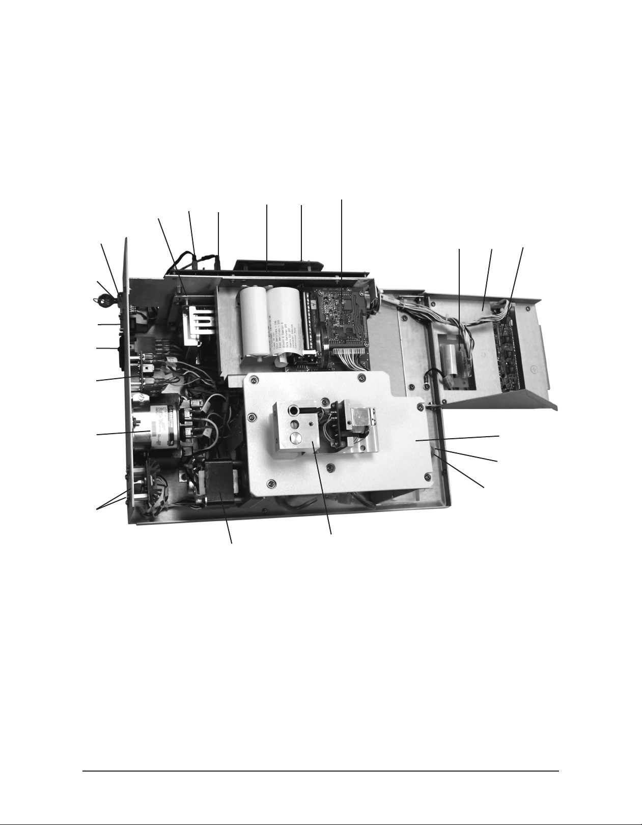
General Overview
(Intel Processor Systems)
Serial Suffix A - C
L
K
J
I
H
G
F
E
D
M
N
O
Q
P
R
S
T
C
B
A. Head
B. Motor
C. Driver Transistors (Stir, Thermoelectric)
D. Motor Capacitor
E. Head Up/Head Down Relays
F. Power Entry Module
G. RS-232C Port
H. Supervisor/Operator Keyswitch
I. Barcode Port
J. Power Supply
K. Sample Probe Plugin
21
U
A
L. Block Probe Plugin
M. Main Board Set, Application PCB
N. Main Board Set, Processor PCB
O. Printer
P. Keypad Transition Board
Q. Keypad
R. Display
S. Deck
T. Heat Transfer Return Tube
U. Heat Transfer Inlet Tube
The Advanced®Model 3250/4250 Service Manual
Page 22
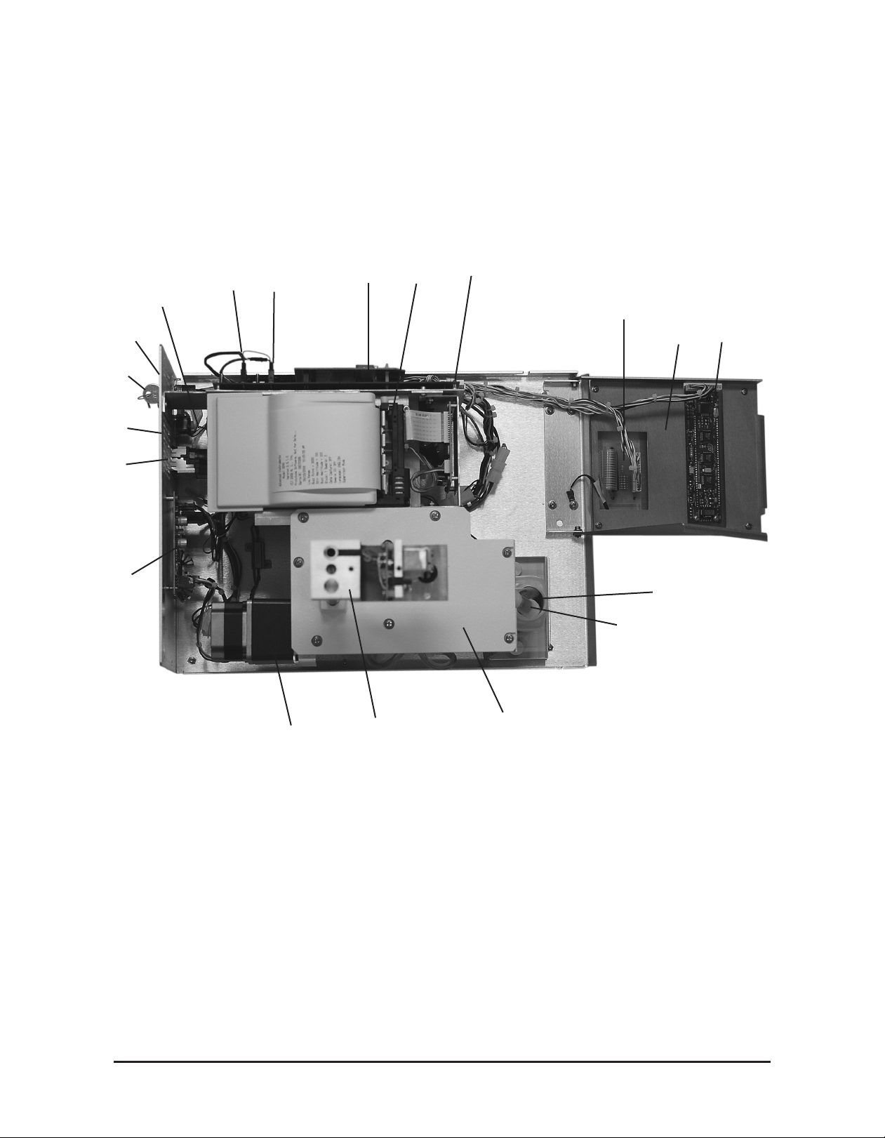
General Overview
(Intel Processor Systems)
Serial Suffix D and Higher
H
(underneath printer)
G
F
E
D
C
J
I
K
L
M
N
O
P
Q
R
B
A. Head
B. Motor
C. Driver PCB
D. Power Entry Module
E. RS-232C Port
F. Supervisor/Operator Keyswitch
G. Barcode Port
H. Power Supply (underneath printer)
I. Sample Probe Plugin
J. Block Probe Plugin
The Advanced®Model 3250/4250 Service Manual
A
S
K. Main Board Set, Processor PCB
L. Printer
M. Main Board Set, Application PCB
N. Keypad Transition Board
O. Keypad
P. Display
Q. Heat Transfer Return Tube
R. Heat Transfer Inlet Tube
S. Deck
22
Page 23

Calibration
The 3250 has two ranges, each with its own
calibration. To calibrate the low range, three
freezing-point tests are required at the 100
mOsm/kg level, and six tests are required at
the 1500 mOsm/kg level. To calibrate the
high range, six freezing-point tests are
required at both the 1500 mOsm/kg level and
the 3000 mOsm/kg level.
The 4250 allows timed or plateau-seeking calibration in either the Hortvet (m°H) or the
Celsius (m°C) scale. Six freezing-point tests
are required at each of the 4250’s two calibration levels:
-408 m°C (-422 m°H), and
-600 m°C (-621 m°H).
Note: If you see the message “Recalibration
Needed”, follow the instrument
prompts to complete the initial calibration. Your calibration may vary slightly
from that mentioned here.
Calibrate the instrument according to the
instructions below:
1. Turn the instrument on.
2. If there is a Supervisor/Operator keyswitch, turn it to the Supervisor position.
It must remain there throughout calibration.
3. Press CALIB to begin the calibration
sequence.
4. The display will prompt you at each calibration level. Place a sample of the first
calibration standard into the freezing
chamber and press START.
5. Continue loading and testing samples at
the first calibration level until the display
prompts you for samples at the second
calibration level.
Refer to the instrument User’s Guide for additional information on calibration.
6. Place the sample of the second calibration
standard into the freezing chamber and
press START.
7. When the instrument has completed calibration, the display will read
"Calibration Complete".
23
The Advanced®Model 3250/4250 Service Manual
Page 24

3250/4250 Circuit Description
The instrument is comprised of the following
functional blocks:
Power Supply
Serial Suffix A - C
The power entry assembly interfaces the AC
voltage presented to the instrument with the
transformer. The transformer provides 120
VAC to the power supply board and the head
motor. The power supply provides the power
to run the main printed circuit board (±12
VDC, ±5 VDC), the thermoelectrics (5 VDC),
the fan (12 VDC), the stir/freeze coil
(12 VDC), and the internal printer (5 VDC).
Note: The internal printer may be powered by
+5 VDC (red/orange wire) or +12
VDC (violet wire). Consult system
schematics for proper service.
Power Supply
Serial Suffix D and Higher
VDC), the stir/freeze coil (12 VDC), the internal printer (12 VDC), and the motor and control circuits (+24 V).
Front End
The sample thermistor measures the temperature of the sample. The thermoelectrics
(whose duty cycle is controlled through the
block probe/thermistor) supercool the sample.
The stir/freeze wire constantly stirs the sample
to guarantee uniform cooling. When the
supercooled sample reaches a set temperature
(3000 mOsm for the low range and 4800
mOsm for the high range, by default, in the
3250, and 3000 mºC in the 4250), the
stir/freeze wire "buzzes" causing the sample
to freeze. During a test, the fan duty cycle
tracks the thermoelectrics duty cycle -10%. If
duty cycle drops below 20%, the fan is off. In
between tests, the fan runs as required to
maintain the software controlled target temperatures.
The power entry assembly interfaces the AC
voltage presented to the instrument with the
AC/DC switching power supply. The power
supply provides the power to run the main
printed circuit board set (±12 VDC, +5 VDC),
the thermoelectrics (5 VDC), the fan (12
Barcode
Port
Serial Port
Head Motor
Controls
Processor
Board
Applications
Board
325605 Control Board Set Description
General: The control board set is made up of
two printed circuit boards in a motherboard/
daughterboard configuration.
Power
Supply
Cooling
System
PrinterKeypadDisplay
The Advanced®Model 3250/4250 Service Manual
24
Page 25

325620/425620/325621/425621
Processor Board
Processor: The processor used is an Intel
80C186 16-bit embedded processor. The
80C186 contains three programmable 16-bit
timers, two serial ports, programmable interrupts, 1 mega-byte of memory address space,
and 64 kilo-bytes of input/output (I/O)
address space. The processor uses an external
32 MHz crystal to generate the internal 16
MHz system clock. The processor controls
access to all memory and all I/O.
Memory Map: The 1 mega-byte of memory
address space contains read-only memory
(Flash EPROM), read/write memory (static
RAM), and the real time clock. About half of
the address space is unused, allowing for
future expansion. The read-only memory is
divided into four sections: reset vector, boot
code, parameter blocks (unused), and applicaiton code. The reset vector tells the processor where to first start executing code; in this
case, the boot code is executed first after
reset. The boot code determines if new software will be downloaded by checking if the
dip switch is in the “PROGRAM” position.
If it is, the boot code waits for new software
to be downloaded through the serial port. If
not, the application code starts.
The real time clock maintains the current date
and time, and contains nonvolatile memory
where the instrument’s operation parameters
are stored. A internal lithium battery preserves the contents of the nonvolatile memory
when the instrument is turned off. Finally, the
read-write memory is used for stacks, variables, etc., except for the small section allocated for the interrupt vectors. The interrupt
vectors tell the processor what code to run
when an interrupt occurs, and functions similarly to the reset vector.
Input/Output Map: The 64 kilo-bytes of
I/O address space control access to all peripherals such as the serial ports, application
board, etc. The processor uses 256 bytes,
called the Peripheral Control Block, to control
the integrated serial ports, timers, interrupts,
chip selects, and I/O pins. The Peripheral
Control Block is fully described in the
80C186EB/80C188EB Microprocessor User’s
Manual. The application board’s registers and
the CPU board’s registers control access to
various functions and are described later.
Memory: Two types of memory are available: read-only and read/write. The chips
used here have 8-bit wide data buses. Used in
pairs, the memory becomes compatible with
the processor’s 16-bit wide data bus. The
read-only memory is implemented using two
128 kilo-bytes x 8 bits Flash EPROMs. Flash
memory is only programmable when a programming voltage (in this case, 12 volts DC)
is applied to the memory; otherwise, it
behaves like read-only memory. The boot
code controls the programming voltage, since
this is the only place where new software can
be downloaded. The read/write memory is
implemented using two 128 kilo-bytes x 8
bits static RAMs.
Watchdog Timer: The watchdog timer provides a mechanism to reset the processor
when the software is not behaving normally.
The software “pets” the watchdog every 100 200 milliseconds. As long as the watchdog is
“petted”, nothing happens. However, if the
software stops “petting” the watchdog, the
watchdog “bites” the processor by activating
the processor’s RESET pin, causing the
processor to reset. The watchdog will also
reset the processor if the power supply falls
below 4.75 VDC. These two features allow
the instrument to recover from abnormal software and hardware conditions.
Please note that all memory addresses and
sizes are always defined in terms of bytes,
even though the processor handles words (1
word = 2 bytes, 1 byte = 8 bits; therefore, 16
bits = 1 word).
25
Real Time Clock (RTC): The real time
clock maintains the current date and time.
The RTC uses an internal clock circuit with
an internal, 10-year life, lithium battery to
The Advanced®Model 3250/4250 Service Manual
Page 26

perform timekeeping. The battery also pre-
erves the contents of internal memory.
s
Dip Switch: The three-position or fourposition dip switch allows the user to download new software via one switch. The other
two switches are available for selecting different operating modes. These operating modes
and the process for downloading software are
described later in this manual.
Voltages: Three voltages are present on the
CPU board: +5 VDC, +12 VDC, and V
.
PP
+5 VDC powers all the logic. +12 VDC is
switched on and off to create the flash memory’s programming voltage, V
.
PP
Glue Logic: The glue logic performs the
functions of creating the RAM memory chip
selects, the Flash memory write signals, the
V
control signal, the watchdog control sig-
PP
nal, and accessing the dip switch. The CPU
board has two software accessible hardware
registers to read the dip switch and to control
watchdog and V
.
PP
Connectors: A 64-pin connector provides
address, data and interrupt signals. A 16-pin
connector provides general chip selects and
serial receive/transmit signals. The application PCB uses a subset of the available signals.
to a 1 mOsm/1.86mºC change. A separate
heatstone bridge circuit is used to measure
W
the voltage across each thermistor probe.
This voltage is first filtered and then sampled
by the analog-to-digital converter. The analog-to-digital converter uses a sigma-delta
conversion technique with on-chip filtering
and a 6.25 VDC reference voltage.
I/O Ports: Circuitry for the two serial ports
(RS-232 and barcode) and the parallel printer
is present on the application board, with
cabling to the actual connectors on the back
panel and the internal printer.
Display & Keypad: The display and keypad
are interfaced to the processor via programmable logic devices (PLDs). The keypad is
polled in a row/column process which identifies the key pressed to the microprocessor.
The application logic, in response to processor commands, controls the LEDs located on
the keypad.
Light Emitting Diodes (LED): LEDs are
provided to indicate when a high current load
is active, a sensor is tripped, or a voltage supply is active. Green LEDs are used on the
power supply voltages, yellow LEDs are used
on driver signals such as the fan and head
motor controls, and red LEDs are used to
indicate that the head up and down optical
sensors have been tripped.
PCB605 Application Board
The application PCB contains all circuitry
specific to the instrument. The board includes
voltage supplies, indicators, analog-to-digital
converters, drive circuitry, parallel ports, serial ports, and various switches.
Analog-to-Digital Converters: Two analogto-digital converters are provided; one for the
sample thermistor probe, and one for the
block thermistor probe. The thermistors vary
in resistance from approximately 2 kilo-ohms
at room temperature, to approximately 10
kilo-ohms at -12ºC. Typically, a 0.6 ohm
change in the thermistor’s resistance equates
The Advanced®Model 3250/4250 Service Manual
Application Logic: The application logic is
made up mainly of two programmable logic
devices (PLDs). These provide software
accessible hardware registers, enabling the
software to read the keypad, sensors, and analog-to-digital converters. These also allow
manipulation of the display, external components such as the fan, head motor, etc., and
interface to the RS-232 ports. The printer is
controlled directly from the microprocessor
through an 8-pin D-latch.
Connectors: Connectors are supplied for the
CPU PCB, display, keypad, power, drives,
probes, and back panel I/O ports.
26
Page 27

Serial (RS-232) Port Interface: An RS-232
ine driver/receiver provides the microproces-
l
sor with a serial port interface that supports
both hardware and software handshaking.
The DB-9 RS-232 port conforms to the DTE
RS-232C standard and has the following pin
assignments:
The stir wire coil is controlled by the rear
anel-mounted darlington transistor
p
(PCB522). The drive circuit consists of a
programmable timer, D/A converter, and
interface op-amps. The timer provides a
square wave of approximately 71Hz, while
the D/A converter controls the output amplitude to the darlington transistor.
Signal Pin Direction
Carrier Detect 1 to 3250
Receive Data 2 to 3250
Transmit Data 3 from 3250
Data Terminal Ready 4 from 3250
Signal Ground 5 common
Data Set Ready 6 to 3250
Request to Send 7 from 3250
Clear to Send 8 to 3250
Note that your instrument is only designed to
support unidirectional communication with an
external device. At this time, there is no protocol for bidirectional communication.
For a sample RS-232 Port Setup, please see
the RS-232 Supplemental Information in the
Appendix at the end of this user’s guide.
Note: This instrument requires the use of a
null modem RS-232C cable. There are
several variations on null modem
cables. Advanced Instruments recommends that you purchase a RS-232C
cable direct from our factory.
Supervisor/Operator Keyswitch Interface:
A PLD is used to interface the supervisor/
operator keyswitch to the microprocessor. In
Operator position, the user cannot change
setup or calibration settings.
Other Circuit Components
Drive Circuitry, Serial Suffix A - C: Drive
circuitry is provided to turn on and off the
four high current loads such as the stir wire,
the head motor, the thermoelectric cooler, and
the fan.
The head motor is controlled by two relays
located at the rear of the chassis that interface
the 120 VAC motor to the DC logic. One
relay raises the head, while the other relay
lowers the head. The relays get their commands from the application board via two
FETs and the application logic. LEDs are
provided on the application board for monitoring the drive signals. LEDs are also provided to monitor the signals from the head
sensor board, described below.
The thermoelectric cooler is controlled by the
FET driver transistor mounted on the rear
panel (PCB520). The FET is, in turn, controlled by the microprocessor through the
PLD application logic. The processor varies
the duty cycle square wave in response to
software commands and block probe resistance.
Drive Circuitry, Serial Suffix D and
Higher: Drive circuitry is provided to turn
on and off four system loads such as the stir
wire, the head motor, the thermoelectric cooler, and the fan.
The stir wire coil drive circuit consists of a
programmable timer, D/A converter, and
interface op-amps on the application board
(PCB605). The timer provides a square wave
of approximately 71 Hz, while the D/A converter controls the output amplitude to the
darlington transistor mounted on the driver
board (PCB523).
The thermoelectric cooler is controlled by the
microprocessor through the PLD application
logic. The processor varies the duty cycle
square wave in response to software com-
27
The Advanced®Model 3250/4250 Service Manual
Page 28

mands and block probe resistance. These sig-
als are provided to the FET driver transistor
n
mounted on the driver board (PCB523).
The head motor is controlled by the application
board via two FETs and the PLD logic. LEDs
are provided on the application board for monitoring the drive signals. LEDs are also provided to monitor the signals from the head sensor
board, described below. Two active low head
up/head down signals are sent to the driver
board (PCB523) where they are converted into
acceleration, direction, and step commands for
the motor drive chip. The motor drive chip
translates these commands into current controlled outputs that move the DC stepper motor
and provide idle torque when no movement is
required. The following adjustments may be
available for the motor circuit: R10 and TP16
are used to set the initial acceleration to a rise
time of 4uS. R21 and TP15 are used to set the
run frequency to 8 Khz.
The fan is controlled by a FET transistor on
the application board, that is interfaced to the
processor through the application logic.
Head Transition Board (M20450) Description: The stir/freeze coil and the sample probe
are connected to the head transition board
which allows easy sample probe replacement.
Head Sensor Board (3D3380) Description:
This board provides two optical sensors that
interface to a PLD on the main board. These
two sensors detect the head-up and head-down
conditions.
Keypad Transition Board (FLO520)
Description: This board provides the interface
to the keypad along with pull-up resistors for
the keypad LEDs.
Barcode Port: A D-type, 15-pin barcode port
is provided in the back of the instrument for
connecting and providing power to such a
device. For proper operation, the barcode port
requires a 1200 bps, RS-232 signal providing
asynchronous serial data containing 1 start bit,
8 data bits, 1 stop bit, and no parity.
Signal Pin Direction
+5V DC 1 to reader
receive data 10 from reader
gnd/earth 9 common
Barcode Port Connections
A suitable barcode scanner is available from
Advanced Instruments. To interface with the
instrument, the barcode scanner must be programmed as follows, referring to the scanner
users guide.
1200 bps
CR suffix
disable beep after good decode
triggerless trigger mode (optional)
Internal Printer, Serial Suffix A - C: The
internal printer assembly (325400) consists of
the sheet metal mounting bracket, thermal print
head (FL0403), thermal printer PCB (FL0402),
and thermal printer PC board assembly
(PCB400). All of this is connected to the application board (PCB605) via cable (M20465).
Note: The internal printer may be powered by
+5 VDC (red/orange wire) or +12 VDC
(violet wire). Consult system schematics
for proper service.
Internal Printer, Serial D and Higher: The
internal printer assembly (325420) consists of
the sheet metal mounting bracket, thermal print
head (325404), main control board (325421),
printer interface board (PCB402), and the control cable (325419). All of this is connected to
the application board (PCB605) via cable
(325415), and on some models via cable
(325033).
The printer interface board (PCB402) contains
the power circuit converting +12 VDC into +5
VDC, a feed/self-test switch (S1), and some
diagnostic LEDs. If the self-test switch is
depressed as instrument power is applied, the
printer will enter self-test mode and print out
settings and a test character set. The LEDs
indicate the operation of the paper-out detector
(D1 yellow) and the door/platen-closed detector
(D2 red). POWER CONNECTION TO J1
The Advanced®Model 3250/4250 Service Manual
28
Page 29

SHOULD NOT BE RECONNECTED
WITH INSTRUMENT POWER ON, OR
DAMAGE TO THE INSTRUMENT MAY
RESULT.
The printer control board (325421) translates
the data from the application board (PDCB605)
into control signals for the print head thermal
elements and drive motor (325404). This board
also contains a factory-set configuration DIP
switch (DS1) and jumper (JP1).
On models equipped with cable (325033), a
compatible version of main board set (325605)
board (PCB402), diagnostic LEDs, and a test
switch are available in the lower right corner
of the larger board (PCB605). D19 is a red
LED that will indicate the printer door/platen
interface is not closed or, if blinking, one of
several printer errors have occurred, requiring
factory assistance. D20 is a yellow LED that
will indicate the paper is out or not detected
when the door is closed. SW1 is a momentary
switch that will cause the paper to advance
when pressed or, if held down while main
power is switched on, will place the printer
into self-test mode.
and a properly configured printer interface
Design Changes
The serial number suffix (referred to in this manual simply as the suffix) indicates the revision of the
instrument. The chart below lists the major changes made at each revision of the 3250 Osmometer and
4250 Cryoscope.
Model 3250
Osmometer Description
Serial Suffix ‘A’ Original model released.
January 2004
Serial Suffix ‘B’ Base chassis and cover reMay 2007 designed.
Serial Suffix ‘C’ Up/Down relay PC boards reOctober 2007 designed into a single RoHS-
compliant PC board.
Serial Suffix ‘D’ **MAJOR REVISION**
September 2009 AC head motor and supporting
components replaced with a DC
stepper motor, multi-driver PC
board and power supply, Seiko
thermal printer assembly with
thread-through paper loading and
supporting components replaced
with a Citizen thermal printer
assembly with easy-load paper
loading.
Serial Suffix ‘E’ Application board redesigned to
October 2010 power display and keypad LEDs
from VCC +5 VDC line. Main
harness redesigned.
Model 4250
Cryoscope Description
Serial Suffix ‘A’ Original model released.
November 2005
Serial Suffix ‘B’ Base chassis and cover reMay 2007 designed.
Serial Suffix ‘C’ Up/Down relay PC boards reOctober 2007 designed into a single RoHS-
compliant PC board.
Serial Suffix ‘D’ **MAJOR REVISION**
September 2009 AC head motor and supporting
components replaced with a DC
stepper motor, multi-driver PC
board and power supply, Seiko
thermal printer assembly with
thread-through paper loading and
supporting components replaced
with a Citizen thermal printer
assembly with easy-load paper
loading.
Serial Suffix ‘E’ Application board redesigned to
October 2010 power display and keypad LEDs
from VCC +5 VDC line. Main
harness redesigned.
29
The Advanced®Model 3250/4250 Service Manual
Page 30

Replacement Parts
Serial Suffix D and higher has some different replacement parts from Serial Suffix A - C, although many
parts have remained common. Before selecting a replacement part, check the serial suffix of the instrument
on the serial suffix label on the rear of the instrument, then refer to the proper section. Refer to the Design
Changes section for additional information.
3250
Common Parts
Block Probe . . . . . . . . . . . . . . . . . . . .4D3340
Clapper . . . . . . . . . . . . . . . . . . . . . .3C2241R
Control Board Set . . . . . . . . . . . . . .325605R
Application Board (only) . . . . . . . .PCB605R
Processor Board (only) . . . . . . . . . .325621R
Cooling Assembly . . . . . . . . . . . . . .3D3300R
Cooling Fan . . . . . . . . . . . . . . . . . . . .4D3360
Cooling Well Inlet Check Valve . . . . .99133R
Firmware “FLASH” Update Kit . . . .SFW008
Fluid Filter . . . . . . . . . . . . . . . . . . . .4D3710R
Fuses: 2.0 Amp . . . . . . . . . . . . . . . . . .70022
1.0 Amp . . . . . . . . . . . . . . . . . .70011
Heat Transfer Fluid Intake
Check Valve . . . . . . . . . . . . . . . .4D3705R
Heat Transfer Fluid Pump Assembly .4D3690
Keypad . . . . . . . . . . . . . . . . . . . . . . .325511R
Load Resistor . . . . . . . . . . . . . . . . . .425150R
Mandrel . . . . . . . . . . . . . . . . . . . . . . .3LH500
NVRAM Battery . . . . . . . . . . . . . . . .71027R
Probe Alignment Tool Kit . . . . . . . . .3LA700
Sample Probe . . . . . . . . . . . . . . . . . . .3D3700
Stir/Freeze Coil . . . . . . . . . . . . . . . .3D2404R
Stir/Freeze Wire . . . . . . . . . . . . . . . . .3LH243
Tube Ejector Spring . . . . . . . . . . . .3D3312R
Yoke . . . . . . . . . . . . . . . . . . . . . . . .3LH230R
4250
Common Parts
Block Probe . . . . . . . . . . . . . . . . . . . .4D3340
Clapper . . . . . . . . . . . . . . . . . . . . . .3C2241R
Control Board Set . . . . . . . . . . . . . .425605R
Application Board (only) . . . . . . . .PCB605R
Processor Board (only) . . . . . . . . . .425621R
Cooling Assembly . . . . . . . . . . . . . .4D3300R
Cooling Fan . . . . . . . . . . . . . . . . . . . .4D3360
Cooling Well Inlet Check Valve . . . . .99133R
Firmware “FLASH” Update Kit . . . .SFW008
Fluid Filter . . . . . . . . . . . . . . . . . . . .4D3710R
Fuses: 2.0 Amp . . . . . . . . . . . . . . . . . .70022
1.0 Amp . . . . . . . . . . . . . . . . . .70011
Heat Transfer Fluid Intake
Check Valve . . . . . . . . . . . . . . . .4D3705R
Heat Transfer Fluid Pump Assembly .4D3690
Keypad . . . . . . . . . . . . . . . . . . . . . . .325511R
Load Resistor . . . . . . . . . . . . . . . . . .425150R
Mandrel . . . . . . . . . . . . . . . . . . . . . . .3LH500
NVRAM Battery . . . . . . . . . . . . . . . .71027R
Probe Alignment Tool Kit . . . . . . . . .3LA700
Sample Probe . . . . . . . . . . . . . . . . . .4D3102
Stir/Freeze Coil . . . . . . . . . . . . . . . .3D2404R
Stir/Freeze Wire . . . . . . . . . . . . . . . . .4LH243
Tube Ejector Spring . . . . . . . . . . . . . .4D3312
Yoke . . . . . . . . . . . . . . . . . . . . . . . .3LH230R
Serial Suffix A - C Parts
Display Board . . . . . . . . . . . . . . . . . .74051R
Head Up/Head down Relay . . . . . . . .3D3109
Motor Assembly . . . . . . . . . . . . . . .4D3350R
Power Supply Assembly . . . . . . . . . .4D3950
Printer Assembly without
Power Harness . . . . . . . . . . . . . .FL2401R
Printer Assembly with Power
Harness . . . . . . . . . . . . . . . . . . . .325400R
Stir Drive Transistor . . . . . . . . . . . .PCB522R
Thermoelectric Drive Transistor . .PCB520R
The Advanced®Model 3250/4250 Service Manual
Serial Suffix A - C Parts
Display Board . . . . . . . . . . . . . . . . . .74051R
Head Up/Head Down Relay . . . . . . .3D3109
Motor Assembly . . . . . . . . . . . . . . .4D3350R
Power Supply Assembly . . . . . . . . . .4D3950
Printer Assembly without
Power Harness . . . . . . . . . . . . . .FL2401R
Printer Assembly with Power
Harness . . . . . . . . . . . . . . . . . . . .325400R
Stir Drive Transistor . . . . . . . . . . . .PCB522R
Thermoelectric Drive Transistor . .PCB520R
30
Page 31

3250
4250
Serial Suffix D and Higher Parts
Display Board . . . . . . . . . . . . . . . . .702041R
Driver PCB . . . . . . . . . . . . . . . . . . .PCB523R
Motor Assembly . . . . . . . . . . . . . . . .325304R
Power Supply Assembly . . . . . . . . .325950R
Thermal Printer Assembly . . . . . . . .325420R
Thermal Printer Mechanism . . . . . .325404R
Upgrade Kit, 3250/4250 Suffix . . . . .325024
D to E
31
The Advanced®Model 3250/4250 Service Manual
Page 32

Supplies & Accessories
3250
100 mOsm/kg Calibration Standard
(10 5-mL ampules) . . . . . . . . . . . .3LA011
500 mOsm/kg Calibration Standard
(10 5-mL ampules) . . . . . . . . . . . .3LA051
900 mOsm/kg Calibration Standard
(10 5-mL ampules) . . . . . . . . . . . .3LA091
1500 mOsm/kg Calibration Standard
(10 5-mL ampules) . . . . . . . . . . . .3LA151
2000 mOsm/kg Calibration Standard
(10 5-mL ampules) . . . . . . . . . . . .3LA201
3000 mOsm/kg Calibration Standard
(10 5-mL ampules) . . . . . . . . . . . .3LA301
100 mOsm/kg Calibration Standard
(110-mL bottle) . . . . . . . . . . . . . .3LA010
500 mOsm/kg Calibration Standard
(110-mL bottle) . . . . . . . . . . . . . .3LA050
900 mOsm/kg Calibration Standard
(110-mL bottle) . . . . . . . . . . . . . .3LA090
1500 mOsm/kg Calibration Standard
(110-mL bottle) . . . . . . . . . . . . . .3LA150
Clinitrol™ 290 Reference Solution
(10 5-mL ampules) . . . . . . . . . . . .3LA029
Osmolality Linearity Set (5 levels) . .3LA028
Protinol® Near Serum Reference
(3 levels) . . . . . . . . . . . . . . . . . . .3MA028
Renol™ Urine Osmolality Controls
(2 levels) . . . . . . . . . . . . . . . . . . . .3LA085
Air Filters, disposable . . . . . . . . . . . .3D2340
Barcode Scanner . . . . . . . . . . . . . . . . .330016
Heat Transfer Fluid . . . . . . . . . . . . . .3DA811
Power Cord (specify voltage and
country) . . . . . . . . . . . . . . . . . . . .----------
Printer Maintenance Kit . . . . . . . . . .FL0425*
Printer Paper, pkg rolls . . . . . . . . . . .FLA835
Printer Paper Roll Holder . . . . . . . . . .FL0408
Sample Tubes (0.2 mL, disposable) .3LA825
Sample Tube Rack . . . . . . . . . . . . . . .3LA846
Serial Port Computer Cable
with DB9S . . . . . . . . . . . .RS232-CABLE
Supervisor Keys . . . . . . . . . . . . . . . . .3D3185
Service Manual . . . . . . . . . . . . . . . . .3255SM
User’s Guide . . . . . . . . . . . . . . . . . . . . . .3255
4250
-422 m°H Calibration Standard
(-408 m°C) . . . . . . . . . . . . . . . . . .3LA023
-621 m°H Calibration Standard
(-600 m°C) . . . . . . . . . . . . . . . . . .3LA033
-530 m°H Lactrol® 530 Reference
Solution (-512 m°C) . . . . . . . . . .3LA030
Air Filters, Disposable . . . . . . . . . . . .3D2340
Barcode Scanner . . . . . . . . . . . . . . . . .330016
Heat Transfer Fluid . . . . . . . . . . . . . .3DA811
Power Cord (specify voltage and
country) . . . . . . . . . . . . . . . . . . . .----------
Printer Maintenance Kit . . . . . . . . . .FL0425*
Printer Paper (5 rolls) . . . . . . . . . . . .FLA835
Printer Paper Roll Holder . . . . . . . . . .FL0408
Sample Tubes marked at 2-mL
and 2.5-mL . . . . . . . . . . . . . . . . . .3LA823
Sample Tube Rack . . . . . . . . . . . . . . .3LA846
Serial Port Computer Cable
with DB9S . . . . . . . . . . . .RS232-CABLE
Service Manual . . . . . . . . . . . . . . . . .3255SM
Supervisor Keys . . . . . . . . . . . . . . . . .3D3185
User’s Guide . . . . . . . . . . . . . . . . . . . . . .4255
*Serial Suffix A - C, only.
How to order:
To order parts, supplies and accessories, contact the Advanced Instruments Customer
Service.
• 800-225-4034 (toll-free within the USA
and Canada)
• +US 781-320-9000 (elsewhere)
• +US 781-320-3669 (fax)
The Advanced®Model 3250/4250 Service Manual
32
Page 33

3. Maintenance
Page 34

Page 35

Cleaning and Maintenance
The cooling assembly should be cleaned once
every two months to insure optimal performance.
To flush the system:
1. Open the door and remove the heat transfer fluid bottle.
2. Empty the contents and fill the bottle
halfway with a solution of 1:5 bleach in
distilled water.
3. Replace the bottle and insert only the tube
with the filter (A). Completely immerse
the filter in the fluid.
4. Insert the return tube (B) into another
container.
5. If there is a Supervisor/Operator
keyswitch, turn it to the Supervisor position.
6. Press TEST to enter the test menu. Press
< or > to select "Head Up Down Test"
and press START.
7. Insert an empty sample tube into the
freezing chamber and press START.
8. Run this test for 10-15 minutes and then
press STOP.
Note: Using the manual primer pump to
complement the head pumping action
can help reduce the time required to
flush the system.
9. Remove the bottle with the diluted bleach
and install a new bottle of heat transfer
fluid. Insert only the tube with the filter
(A).
10. Press START twice. Run this test until
the colored fluid begins draining out of
the return tube, and then press STOP.
11. Remove the return tube from the container and insert it into the heat transfer fluid
bottle. Do not immerse the return tube in
the heat transfer fluid (B).
12 Press STOP to exit the menu.
To drain the system:
1. Turn off the power and unplug the instrument. Remove the cover.
2. Remove the heat transfer fluid bottle and
empty the contents.
B
A
35
3. Replace the empty bottle and insert the
tubes.
4. Press gently on the pump at the bottom of
the head. Slide until all liquid has been
expelled (the unit may need to be tipped
on its side to remove the liquid).
The Advanced®Model 3250/4250 Service Manual
Page 36

Removing the Head Cover & the Instrument Cover
Tools Needed: Flat-bladed screwdriver,
Phillips screwdriver.
Warning-Hazardous Voltage
Warning-Internal components may
be damaged by static electricity.
CAUTION: Improper connections
may cause damage to the instrument.
1. Turn off the power and unplug the instrument.
2. Remove the two screws from the head
cover (A) and lift off the head cover.
3. Serial Suffix A: Remove the two screws
from the front (B) and the four screws
from the rear panel (C).
Serial Suffix B & C: Remove the four
screws from the rear panel (C).
Serial Suffix D and Higher: Press the
printer cover release button (D), then
remove the four screws from the rear
panel (C).
4. Serial Suffix A: Slide the instrument
cover up and off.
Serial Suffix B and Higher: Slide the
instrument cover forward, then up and
off.
A
B
C
The Advanced®Model 3250/4250 Service Manual
D
36
Page 37

Osmometer/Cryoscope Well Cleaning
Use this procedure to clean the well and tubing of any foreign matter (e.g., broken glass)
that may have fallen into the well.
Tools needed: Flat-bladed screwdriver;
Phillips screwdriver; Tru-arc pliers; thin, stiff
wire; 4” cable tie; small wire cutters.
Osmometer Well Cleaning
1. Turn off the power and unplug the instru-
ment.
2. Remove the head cover and instrument
cover (see Removing the Head Cover &
the Instrument Cover).
3. Drain the cooling system (see Cleaning
and Maintenance).
4. Disconnect the fluid pump from the cool-
ing well, as follows:
C
6. Remove the white Delrin elevator and
spring (C). (Save for replacement when
cleaning is complete.)
7. Inspect the bottom of the well and
remove any visible debris. Be sure to
clean out the small hole at the bottom of
the well.
B
a. Unwrap refrigeration tape (A). Save
for re-use during reassembly.
b. Cut and remove the cable tie.
c. Pull the tubing off of the cooling well
inlet port.
5. Using a pair of Tru-arc pliers, remove the
Tru-arc retainer ring (B) from inside the
well. (Save the retainer ring for replacement when cleaning is complete.)
A
8. Using a thin stiff wire, insert it into the
well inlet port.
Note: The wire diameter MUST be small
enough to pass through, into the well.
The .050” diameter X 4.00” long
4LH243 stir wire is ideal.
9. Push the wire into the well. Repeat this
process several times, sliding the wire
back and forth until the end of the wire is
visible in the hole at the bottom of the
well. (This should loosen any deposit
trapped in the tube and the well.)
10. Reassemble the pump tubing to the well,
apply the cable tie, and then reapply the
refrigeration tape.
11. Using a solution of 1:5 bleach in distilled
water, place the filter and well return line
into this solution. Manually press the
pump up and down until the solution has
37
The Advanced®Model 3250/4250 Service Manual
Page 38

circulated through the pump and well,
nd into the bottle.
a
12. When satisfied that the solution is freeflowing, flush the bleach solution with
clean water, then stop and drain the cooling system.
13. Reassemble the instrument by replacing
the spring (C) and elevator (B), securing
with the Tru-arc retaining ring, then
replace the head cover and instrument
cover.
14. Add a new bottle of heat transfer fluid
and prime the pump. The instrument is
ready for testing.
Cryoscope Well Cleaning
1. Turn off the power and unplug the instrument. Remove the heat transfer fluid
from the front cover.
D
2. Follow steps 2-4 from the Osmometer
Well cleaning instruction (previous page).
3. Remove the spring (D) from the well and
set aside, to be replaced after cleaning.
Note the orientation of the spring as you
remove it from the well, wide-end down.
4. Follow steps 7-12 from the Osmometer
Well Cleaning instruction.
5. Replace the spring (wide-end down) into
the well and reassemble the instrument by
replacing the instrument cover and the
head cover.
6. Add a new bottle of heat transfer fluid
and prime the pump. The instrument is
ready for testing.
The Advanced®Model 3250/4250 Service Manual
38
Page 39

Cleaning and Lubricating the Printer
(Serial Suffix A - C, only)
Use this procedure to clean and lubricate the
printer feed mechanism.
Tools needed: Nyogel 744 lubricant and
cleaning patches (Printer Maintenance Kit
FL0425).
1. Open the printer cover on the top of the
instrument. There is no need to shut off
power or remove any of the instrument
covers to perform this maintenance.
2. If paper is installed in the printer, cut the
paper between the printer mechanism and
the paper roll, then remove the paper roll.
3. Remove the paper from the printer mechanism by pulling it forward through the
printer mechanism. If necessary, use the
FEED key on the instrument keypad or
the printer paper feed button (A) to
advance the paper.
CAUTION: DO NOT PULL THE PAPER
BACK THROUGH THE
PRINTER. THIS WILL DAMAGE THE PRINTER PAPER
FEED MECHANISM.
4. Use a cleaning patch to wipe all grease
from the printer bar (B).
5. Apply three drops of Nyogel 744 evenly
across the entire printer bar.
6. Press either the FEED key on the instrument keypad or the printer paper feed button to exercise the printer paper feed
mechanism 5-to-10 cycles to evenly distribute the lubricant over the printer bar.
7. Wipe the printer bar with a fresh cleaning
patch.
8. Lubricate hte printer bar a second time
with three evenly-spaced drops of Nyogel
744.
9. Press either the FEED key on the instrument keypad or the printer paper feed button to exercise the printer paper feed
mechanism 5-to-10 cycles to evenly distribute the lubricant over the printer bar.
10. Reinstall the printer paper (see User’s
Guide).
11. Feed paper through the slot in the printer
cover, then close the printer cover to complete maintenance.
12. Instrument is ready for use.
A
B
39
The Advanced®Model 3250/4250 Service Manual
Page 40

Probe & Stir/Freeze Wire Alignment
Proper alignment and adjustment of the mandrel, probe and stir/freeze wire are of utmost
importance to assure accuracy, precision and
proper operation of the instrument.
Note: After making any probe and/or
stir/freeze wire adjustments, the
instrument calibration must be checked
and adjusted as necessary.
Use the probe alignment tool and follow the
Probe Alignment Tool instructions located in
the Replacement Instructions section of this
manual.
The Advanced®Model 3250/4250 Service Manual
40
Page 41

4. Troubleshooting
Page 42

Page 43

Introduction
Problems with the performance of the
3250/4250 are usually identified by the software and displayed as error messages. The
troubleshooting table on the following pages
lists all error messages, indicates why the
software generated the message, and lists
what may be causing the problem.
Error messages may be caused by mistakes
during testing, worn or defective parts, or
parts set to the wrong specifications. This
section includes directions for:
• checking and resetting the stir & freeze
amplitude settings and the probe bin settings;
• aligning the probe and stir-freeze wire, and
adjusting the head sensors;
• using the A/D test to check the block
probe, sample probe, and cooling assembly.
NOTE: Before you repair or replace any
parts, turn the instrument off and
then back on after a short delay.
This allows the software to reinitialize, and may correct what appears to
be a serious hardware problem.
CAUTION: Some troubleshooting requires
the instrument to be turned on
while the cover is removed.
Use extreme caution when operating the instrument without the
cover. Hazardous voltages are
present at the AC input and circuit components connected
directly to the AC input. Refer
to the system schematic for
additional information.
43
The Advanced®Model 3250/4250 Service Manual
Page 44

Freeze “Buzz” Amplitude
To check and reset the freeze amplitude setting:
1. Turn on the instrument. If there is a
Supervisor/Operator keyswitch, turn it to
the Supervisor position (if required).
2. Press TEST. Press < or > to select “Stir/
Freeze Test”, and then press START.
3. At “[stir] [freeze]”, watch the tip of the
stir/freeze wire and press >. The freeze
vibration should buzz loudly, and the
vibration blur at the tip of the wire will
last one second. The amplitude should
measure about 13mm (1/2”).
If the freeze amplitude is not within the
correct range, follow steps 4-6 below.
4. Remove the head cover and clear away
any metal chips between the coil frame
and the clapper (A).
5. Check the position of the yoke (B) and
clapper. The yoke must be 90º and flush
against the back wall of the head. Bend
the yoke if the clapper appears too close
or too far away from the coil frame. The
clapper does not have to be directly parallel to the back wall of the unit.
6. Adjust the freeze “buzz” amplitude, as
described in the user’s guide Chapter 2:
Changing Operating Settings:
B
A
The Advanced®Model 3250/4250 Service Manual
44
Page 45

Stir Driver Noise
(Serial Suffix A - C, only)
Excessive noise in the stir amplitude and frequency can affect the quality of the stir signal
and introduce excessive pre-freeze errors or
cause poor freeze pulse repeatability. The
presence of such noise can best be determined
with the use of an Oscilloscope.
1. Connect the Oscilloscope between J9-1
and ground.
2. Turn on the instrument. If there is a
Supervisor/Operator keyswitch, turn it to
the Supervisor position (if required).
3. Press TEST. Press < or > to select “Stir/
Freeze Test”, and then press START.
4. At “[stir] [freeze]”, press <.
The stir wire driver signal should be a clean,
square wave at approximately 72 Hertz and
4Vdc (see figure 1). If not, verify that two
ferrite beads are present in your unit, as
shown in Installation Option A or B, below.
Figure 2. Can be cleaned up with ferrite bead.
Acceptable if stir wire not affected.
If the beads are missing, purchase Advanced
Instruments Part No. 91035 and install, as
shown.
If the beads are present and you still have
noise as shown in figures 3 or 4, replace the
driver transistor PCB522.
Figure 1. Good signal.
Figure 3. Not acceptable. Replace stir wire driver
or use ferrite bead.
Figure 4. Not acceptable. Replace stir wire driver
or use ferrite bead.
45
The Advanced®Model 3250/4250 Service Manual
Page 46

Installation Option A:
Ferrite Beads
NOTE: For installation option A, two ferrite beads are installed on the white wire exiting the head shaft
and attached to TR2 on the head transitionn board.
Installation Option B:
Ferrite Bead
Ferrite Bead
NOTE: For installation option B, one ferrite bead is locat-
ed on the light blue wire running between PCB522
pin 4 and J3B. The second ferrite bead is located
on the white wire exiting the head shaft and
attached to TR2 on the head transition board.
The Advanced®Model 3250/4250 Service Manual
46
Page 47

Head Sensor Adjustment
1. Turn off the power and unplug the instrument. Remove the instrument cover and
the head cover. Place an empty sample
tube in the sample well.
2. Manually push the head all the way down
until the head stop screw (A) meets the
base of the deck (B).
A
B
C
D
E
3. The head position sensors are located on
the head sensor board. To adjust the head
sensor position, use an Allen wrench and
loosen the two bracket screws (C), and
move the board (D) and bracket (E) either
up or down until the head sensor flag (F)
is in the middle of the head down sensor
(G).
Note: To facilitate access to the two bracket
screws (C), loosen and move the printer bracket assembly.
F
Note: Your instrument is equipped with a
series of diagnostic LEDs on the main
application board PCB605 to allow
visual identification of drive signals
and sensor activation.
• The yellow LEDs marked “Drive
Up” and “Drive Dn” indicate that
the control electronics have issued a
command to the head motor relays.
• The red LEDs marked “Head Up”
and “Head Dn” indicate that the
corresponding optical sensor has
been tripped.
G
47
The Advanced®Model 3250/4250 Service Manual
Page 48

Head Up/Down Test
1. Turn on the instrument. If there is a
Supervisor/Operator keyswitch, turn it to
the Supervisor position (if required).
Place an empty sample tube in the sample
well.
2. Press TEST. Press < or > to select
“Head Up/ Down Test”, and then press
START.
3. Place an empty sample tube into the
freezing chamber.
4. At “[START] Test [STOP]”, press
START.
The head should move continually up and
down.
Use this test to ensure the following components are working properly:
• The motor (A) is running.
• The gears (B) are turning properly.
• The sensors (C) are detecting the head-up
and head-down conditions.
• The sample well fluid passage (D) is not
obstructed by debris, and the pump is moving the heat transfer fluid into the freezing
chamber.
Note: If the sample well fluid passage is
obstructed, disassemble and clean the
sample well following the instructions
found earlier in this section. Also,
examine the one-way check valve (E)
to make sure it is not stuck open or
closed.
Note: Your instrument is equipped with a
series of diagnostic LEDs on the main
application board PCB605 to allow
visual identification of drive signals
and sensor activation.
• The yellow LEDs marked “Drive
Up” and “Drive Dn” indicate that
the control electronics have issued a
command to the head motor relays.
• The red LEDs marked “Head Up”
and “Head Dn” indicate that the
corresponding optical sensor has
been tripped.
A
B
The Advanced®Model 3250/4250 Service Manual
E
C
48
D
Page 49

Power On Diagnostics
Place a tube with saline or distilled water in
the sample well. Turn on the instrument At
“Press START to Continue”, press START.
The instrument performs a check of the cooling assembly and the probes. If a Block
Probe Failure, Sample Probe Failure or
Cooling System Error message displays, use
the A/D tests to perform further testing.
A/D Tests
Note: You must set the correct sample and
block bin numbers before performing
A/D tests.
1. Turn on the instrument. If there is a
Supervisor/Operator keyswitch, turn it to
the Supervisor position (if required).
2. Press TEST.
3. Press < or > to select “A/D Tests”. Place
a sample tube containing either isopropyl
alcohol or a high value standard into the
freezing chamber, and press START.
Block probe in degrees Celsius,
Sample probe in degrees Celsius, or
Cooling block duty cycle (a % value).
Block probe resistance will indicate current
temperature. The probe begins to cool after
the target temperature is set, and the resistance increases until it reaches the target temperature.
Sample probe resistance will indicate current temperature. The probe begins to cool
after the target temperature is set, and the
resistance increases until it reaches the target
temperature. Due to thermal mass considerations between the positions of the block and
sample probes, the sample probe may be ±
0.5ºC of the block probe reading.
Duty cycle displays the percentage of time
that the thermoelectrics power is on. When
the thermoelectrics begin to cool, the duty
cycle is usually at 100%. As the instrument
stabilizes, the duty cycle decreases to around
60%.
4. The display will change to:
off Blk NNNN.NN ohm
readout
(resistance or temperature)
channel setting
(sample or block)
target temperature
(off, +1 to -8)
5. Set the target temperature from +1°C to
-8°C by pressing < sequentially.
6. Press > sequentially to read:
Block probe resistance in ohms,
Sample probe resistance in ohms,
Increased ambient operating temperatures do
not affect the sample probe reading, but will
increase the observed duty cycle, up to 85%
at the maximum temperature of 35ºC.
Variations in ambient non-condensing relative
humidity have no effect on the sample probe
reading or duty cycle.
The following situations indicate a problem
with either the probes or the cooling assembly:
• The resistance reading is replaced by the
number 0. Scrolling from right to left indicates an open circuit.
• The target temperature cannot be reached,
but probe readings that vary around ambient indicate a cooling system problem.
49
The Advanced®Model 3250/4250 Service Manual
Page 50

To determine if a faulty probe is causing the
roblem:
p
1. Disconnect the probe from the main
board.
2. Place a 6 Kohm fixed resistor across pins
1 and 2.
Sample Bin Setting
If you do not know the sample bin number, or
if you want to verify the sample bin number:
1. Turn on the instrument. If there is a
Supervisor/Operator keyswitch, turn it to
the Supervisor position (if required).
3. If the resistance display changes to
approximately 6,000 ohms, replace the
probe.
If the resistance does not change, replace
the main control board or application
board.
If the resistance on both channels does not
increase, or if the temperature reads approximately ambient while a target temperature is
set, the situation indicates a problem with
either the cooling assembly or application
board.
To determine which component is faulty:
1. Remove the empty tube from the freezing
chamber.
2. Set the target temperature to -8.
3. Raise the head manually and place a thermometer inside of the freezing chamber.
2. Press TEST. Press < or > to select
“Probe Bin Test”, and then press
START.
3. Place a sample of Probe Bin-Setting Fluid
into the freezing chamber.
4. At “[START] Ready?”, press START.
5. At the end of the test, record the sample
probe resistance and the bin number, and
then press STOP. The display will
change to “Probe Bin Test”.
To set the correct sample bin number, follow steps 6-8.
If the current sample bin number matches
the number just recorded, press STOP
twice to exit the menu.
6. Press SETUP. The Supervisor/Operator
keyswitch must be in the Supervisor position.
4. If the temperature inside the freezing
chamber drops to approximately -8ºC, the
cooling assembly is working, and the
application board needs to be replaced.
If the temperature remains at room temperature, replace the cooling assembly.
Note: When the A/D channel is open, there is
a thirty-second delay in response to
any resistance change.
CAUTION: If the A/D test sample freezes,
allow it to thaw before attempting to remove the sample probe.
The Advanced®Model 3250/4250 Service Manual
7. At “Select Setup Item”, press < or > to
select “Select Sample Bin #”, and then
press START.
8. If the current sample bin number is not
the same as the one recorded in step 5,
enter the correct number, press ENTER
twice, and then press STOP twice to exit
the menu. Recalibration will be required.
50
Page 51

Block Bin Setting
1. Turn off the power and unplug the instrument. Remove the cover and record the
block probe bin number located on the
block probe wire.
2. Replace the cover. Plug in the instrument
and turn it on. If there is a Supervisor/
Operator keyswitch, turn it to the
Supervisor position (if required).
4. If using a glass sample tube, check the
etting by placing a sample (water or
s
standard solution) in position on the
probe. If bubbles form in the sample, or
if the stir wire hits the tube, the current
setting is too high and must be adjusted
downward.
5. When the setting is correct, record the
new stir amplutide number for your
records, and press ENTER.
3. At “Press START to Continue”, press
SETUP.
4. At “Select Setup Item”, press < or > to
select “Select Block Bin #”, and then
press START.
5. Enter the correct number and then press
ENTER twice.
6. Press STOP to exit the menu.
Recalibration will be required.
Stir Amplitude
1. Turn on the instrument. If there is a
Supervisor/Operator keyswitch, turn it to
the Supervisor position (if required).
2. Press SETUP. Press < or > to select “Set
Stir Amplitude”, and then press START.
6. At “Set Stir Amplitude”, press STOP to
return to “Osmometer (or Cryoscope)
Ready”.
Note: Stir wire movement should be stable.
If movement has erratic amplitude,
driver transistor PCB520 may need
replacement. Use an oscilloscope at
J9-1 to verify the presence of a clean,
square wave (see Stir Driver Noise
procedure).
Display/Printer Test
1. Turn on the instrument. If there is a
Supervisor/Operator keyswitch, turn it to
the Supervisor position (if required).
2. Press TEST. Press < or > to select
“Display/Printer Test”, and then press
START twice.
3. Watch the vibration blur at the tip of the
stir/freeze wire. If the amplitude is not
within the range specified below, press >
to increase the amplitude, or press < to
decrease the amplitude. (The default is
100, but your value may differ.)
3250: The stir wire movement should be
no wider than the width of the
sample probe.
4250: The stir wire movement should be
twice the width of the sample
probe.
51
A continuous string of characters and
numbers should scroll across the display,
and a single string of the same characters
and numbers will be sent to the printer.
If not, check your connections and try
again. If you continue to have a problem
and the instrument is working otherwise,
the printer or display may need to be
replaced (see Replacement Instructions
for additional information).
3. Press STOP twice to end the test and exit
the Test menu.
The Advanced®Model 3250/4250 Service Manual
Page 52

Beeper Test
Barcode Test
1. Turn on the instrument. If there is a
Supervisor/Operator keyswitch, turn it to
the Supervisor position (if required).
2. Press TEST. Press < or > to select
“Beeper Test”, and then press START
and < to activate the continuous internal
beeper.
If you do not hear the beeper and the
instrument is working otherwise, the
application board may need to be replaced
(see Replacement Instructions for additional information).
3. Press STOP twice to end the test and exit
the Test menu.
Note: This test will only function if Power On
Diagnostics has been completed.
1. Turn on the instrument.
2. Press TEST. Press < or > to select
“Barcode Test”, and then press START
to activate the barcode test. Using the
attached scanner, begin scanning barcodes. Each scan should display on the
instrument.
If the barcode does not display, check the
connections. Try resetting the scanner to
the factory defaults using the scanner
manual or included Advanced Instruments
documentation. Verify with the scanner
manual that the type of barcode you are
using is activated.
If you are still having problems, contact
Advanced Instruments for service.
3. Press STOP twice to end the test and exit
the Test menu.
Keypad Test
1. Turn on the instrument. If there is a
Supervisor/Operator keyswitch, turn it to
the Supervisor position (if required).
2. Press TEST. Press < or > to select
“Keypad Test”, and then press START to
activate the keypad test. Each key
pressed should respond on the display
with the key name, and activate the corresponding LED, if present.
If any keys or LEDs do not respond,
check the narness connections and repeat
the test. Otherwise, the keypad or application board may need to be replaced (see
Replacement Instructions for additional
information).
3. Press STOP twice to end the test, and
STOP again to exit the Test menu.
Note: This test will only function if Power On
Diagnostics has been completed.
Reset Serial Number
The instrument serial number appears when
you power up the instrument. If you need to
reset the serial number:
1. If there is a Supervisor/Operator
keyswitch, turn it to the Supervisor position (if required).
2. At “Press START to Continue”, press
SETUP.
3. Cycle through the menu options by pressing < or > until you reach “Serial
Number”, and then press START. The
display will read “Serial#:********”.
The Advanced®Model 3250/4250 Service Manual
52
Page 53

4. Press the following keys consecutively:
, 4, CLEAR. The displayed serial num-
2
ber will disappear.
5. Enter each digit of the serial number as it
appears on the label on the back of the
instrument (Note: the letter suffix at the
end of the serial number will not be
entered). When the number is correct,
press ENTER.
The serial number will be recorded in
memory and should appear the next time
you power up your instrument.
53
The Advanced®Model 3250/4250 Service Manual
Page 54

Instrument Software Updates
Software for Advanced Instruments model
3250/4250 instrument is contained in factoryinstalled integrated circuits called Flash
EPROMs, “Electrically Erasable Programmable Read-Only Memory”, and is sometimes referred to as “Firmware”.
This type of memory is furnished in two
PLCC (Plastic Lead Chip Carrier) devices on
the 325620/425620/325621/425621 processor
board at locations U3 and U4. U3 is the
lower 8 bits of the 16-bit processor address
bus, and U4 is the upper 8 bits.
Advanced Instruments products using this
“FLASH” technology can be field-updated
using a Windows PC and Advanced
Instruments serial cable. For the latest
instructions on performing the RS-232 port
firmware upgrade, consult the documentation
supplied with the upgrade package. For information on available updates, consult
Advanced Instruments or your dealer.
4. Perform the download, using the instructions provided with the update software.
After download is complete, the instrument will reboot and report the new software version.
5. Turn off the instrument and return the
Operator/Supervisor keyswitch to the
desired position.
Method with cover removed
Note: Since this procedure requires opening
the case, this update should be performed only by an authorized technician.
1. Turn off the power and unplug the instrument.
2. Remove the instrument cover (see section
2 for instructions on removing the instrument cover).
Performing FLASH firmware update
Performing this update should not affect any
of your calibrations or system settings unless
the update has made changes to this area of
memory. For specific information, consult
the documentation included with the update.
Method without opening cover
Your instrument has a three-position
Operator/Supervisor keyswitch.
1. Turn off the instrument. Select the 45º
position between Operator and
Supervisor.
2. Attach the Advanced Instruments serial
cable between your PC and the instrument.
3. Turn on the instrument. The display
should read “Flash BOOT Program”.
3. Locate the
325620/425620/325621/425621 processor
board (smaller of two).
4. Locate SW1 dip switch on the processor
board if it is a 3-position switch. Locate
switch position 3 (lower switch) and
select the CLOSED, ON, or 1 position. If
it is a 4-position switch, locate switch
position 1 (upper switch) and select the
CLOSED, ON, or 1 position. Do not
change any other switch setting.
5. Attach the Advanced Instruments serial
cable between your PC and the instrument.
6. Plug in and turn on the instrument. The
display should read “Flash BOOT
Program”.
7. Perform the download, using the instructions provided with the update software.
The Advanced®Model 3250/4250 Service Manual
54
Page 55

After download is complete, the instru-
NOTES:
1) ON = 1 = CLOSED
OFF = 0 = OPEN
2) Seiko printers are used with Serial Suffix A - C; Citizen printers are used with Serial Suffix D and higher.
Refer to Design Changes for additional information.
Option Switch Setup Table - 3-Position Switch
Switch Function
Selections
1 2 3
#1 Selects Instrument
3250 ON
4250 OFF
#2 Selects Printer
Citizen ON
Seiko OFF
#3 Selects Mode
Program ON
Normal Operation OFF
SW1
Option Switch Setup Table - 4-Position Switch
Switch Function
Selections
1 2 3 4
#1 Selects Mode
(“PROG”)
Flash Boot ON
Normal Operation OFF
#2 Selects Printer
(“OPT1”)
Citizen ON
Seiko OFF
#3 Selects Instrument
(“OPT2”)
3250 ON
3250 OFF
#4 Not in Use
(“OPT3”)
N/A ON
N/A OFF
SW1
ment will reboot and report the new software version.
ment does not function correctly, consult the
rest of this service manual before contacting
Advanced Instruments for service.
8. Turn off the power and unplug the instrument.
9. Restore SW1 position 3 (3-position
switch) to the OPEN, or position 1 (4position switch) OFF, or 0 position.
10. Replace the instrument cover.
11. Reattach the power cord and return the
instrument to use.
If any problems occur, check the connections
and switch position settings, and then try the
download again. If after download the instru-
Option Switch Settings
The processor board is equipped with a dip
switch. Each switch position and combination of positions can be used to configure different programming options, such as the programing option listed above for Flash update
mode.
If your settings should accidentally get
changed, or your replacement processor board
is shipped from the factory with the incorrect
settings for your product, the following tables
detail the appropriate switch positions for
restoring your instrument to proper operation.
55
The Advanced®Model 3250/4250 Service Manual
Page 56

Troubleshooting Table
Symptom Explanation Suggested Action
1. Abrupt loss of power
(no display)
2. “A/D Init Failure”
“A/D High Filter Error”
“A/D Low Filter Error”
“A/D Cal Mode Error”
Interrupted power connection or loss of
power.
One or both A/D converters lost initialization.
1. Make sure the power cord is firmly
plugged into both the wall outlet and the
socket on the back of the instrument.
2. Temporarily unplug the power cord from
its wall outlet and replace it with a known
workable lamp or small appliance. Have
the power restored.
3. Measure the AC voltage supplied at the
power outlet used for this instrument.
4. Unplug the power cord from the power
cord socket. Visually check the fuses for a
blown fuse. If there is any doubt, test the
fuses with a continuity checker or ohmmeter or simply replace them.
5. Check the values marked on the fuses.
6. Replace blown or incorrect-value fuses
with time delay (T) fuses. Refer to instrument serial number label for proper fuse
value.
7. If a fuse was blown and a replacement
fuse blows too, contact our product service department for assistance.
1. Turn power off and on.
2. If problem persists, replace application
board.
3. “Baudrate Error”
4. “Block Probe Failure”
5. "Block Probe Open?"
6. Buzz Point Default Set
7. “Calibration Cancelled”
8. “Calibration Out of
Range; Repeat”
The baudrate setting is out of range.
The block probe has failed (usually
shorted).
The block probe resistance is greater
than A/D converter can measure.
The freezing point setting was outside
the allowed range.
The default setting has been automatically set.
The STOP button was pressed during
calibration.
The range of the samples tested did not
repeat well enough for calibration.
Reset baudrate in SETUP menu.
Check the block probe resistance (2,300
ohms ±300 at room temp.)
1. Is the probe plugged in?
2. Check the block probe resistance (2,300
ohms ±300 at room temp.)
1. For the 3250, use SETUP menu to
change, if desired.
2. For the 4250, this is a fixed value.
Calibration cancelled.
1. Recalibrate the instrument.
2. Check freeze pulse.
3. Check sample size and quality.
4. Check probe alignment.
The Advanced®Model 3250/4250 Service Manual
56
Page 57

Symptom Explanation Suggested Action
9. "Check Calibration"
(3250 only)
10. “Cooling System
Error”
11. “Count Error;
Parameter RAM”
12. Display blank or has
blinking cursor
13. Display flashing or
scrolling rapidly
14. EPROM Failure
Buzz point setting has been changed.
The cooling assembly may not be functioning properly.
A memory check error occurred in the
RAM.
Display has experienced a voltage drop
below its reset threshold.
Display is functioning normally, but is
displaying an abnormal message (message length exceeds 20 characters).
This indicates a memory error with the
FLASH memory.
1. Spot-check calibration.
2. Recalibrate, if needed.
1. Check the cooling assembly.
2. Make sure there is heat transfer fluid in
the cooling well.
3. Verify control signal using LED D16.
4. Let unit warm up and try Power On
Diagnostics again.
1. Turn the power off and on.
2. If problem persists, replace processor
board.
1. Turn power off and on.
2. If problem persists, replace application
board.
1. Press STOP if in diagnostics.
2. If problem persists, contact Advanced
Instruments for Hot-Line Service.
1. Try restarting the instrument.
2. Replace the processor board.
15. "Error Reading
Barcode”
16. ESC TRAP
17. “Event Record Lost”
18. “Fan System Failure”
The data received from the barcode
reader was not formatted correctly.
Was the barcode over 13 characters
long?
Indicates general operating system code
fault.
The instrument has lost its record from
memory.
The fan is not functioning properly.
1. Turn the power off and on.
2. Check barcode scanner settings.
3. If problem persists, replace application
board.
1. Turn the power off and on.
2. Replace the processor board.
1. Turn the power off and on.
2. If problem persists, replace processor
board.
1. Check fan driver/control circuit.
a. Make sure the fan is plugged in.
b. Make sure the fan isn’t blocked.
c. Check the fan driver LED on the appli-
cation board.
d. To check fan, disconnect and connect
to bench-top 12 VDC power supply.
2. Replace the fan or application board.
57
The Advanced®Model 3250/4250 Service Manual
Page 58

Symptom Explanation Suggested Action
19. “Flash Boot Program”
20. ‘FPE_INTOFLOW”
“FPE_INTDIV0”
“FPE_INVALID”
“FPE_ZERODIVIDE”
“FPE_OVERFLOW”
“FPE_UNDERFLOW”
“FPE_INEXACT”
“FPE_STACKFAULT”
“FPE_EXPLICITGEN”
“FPE_UNDEFINED”
21. “Head Not Up”
“Head Not Down”
The instrument is configured to receive
Flash EPROM updated code.
Indicates various floating point math
errors have occurred.
The head up/down mechanism may not
be functioning properly.
1. If intentional, perform download process
as described in this manual.
2. If not intentional, turn off power and set
three-position Operator/Supervisor keyswitch to Operator or Supervisor position.
3. Check processor board option switch
SW1 position 3 and set to OPEN/OFF/0
(see Option Switch Setup Table).
1. Turn the power off and on.
2. Replace the processor board.
1. Check the motor, clutch assembly and
relays by running the head up/down test.
2. Check the Head Up or Head Down position sensor.
3. Check LED indicators on application
board.
22. ID None
23. “Insufficient Data”
24. Keypad keys unresponsive
25. Low Battery
No sample ID was recorded when test
was run.
Less than two valid results were found
in the requested statistics calculation.
Connections to the keypad may have
become disconnected, or the keypad has
failed.
The lithium battery contained inside the
NVRAM memory is too low to maintain
stored information, calibration, and system settings. The instrument will function normally as long as the main power
remains on.
1. Are you using ID? If no, ignore message.
2. Verify ID # prints at the end of your test.
3. Reboot and check for Low Battery message.
1. Change the number of samples requested
for statistical calculations.
2. Continue testing to add more results to
the buffer.
1. Check circuit connections to the keypad
(refer to system schematic).
2. Replace the keypad.
Contact Advanced Instruments for Hot-Line
Service.
The Advanced®Model 3250/4250 Service Manual
58
Page 59

Symptom Explanation Suggested Action
26. Low Fluid Level in
Freezing Chamber
27. Memory Allocation
Error
28. “New Software
Version”
29. “No Parameters in
RAM”
“Parameter RAM
Failed”
1. The heat transfer fluid pump may be
malfunctioning, or there may be a
leak or obstruction in the fluid system.
2. An insufficient amount of fluid is
being pumped with each head
up/down cycle.
Internal memory management error,
allocated reserved memory conflict.
EPROM has been changed, or new software has been downloaded.
The battery-backed RAM has lost its
data or has been cleared.
The instrument has lost the calibration,
data, and probe bin numbers from memory.
This may occur during some software
updates.
1. Evaluate the functioning of the heat transfer fluid pump per the instructions found
in the Maintenance section.
2. If an obstruction is suspected, refer to
Osmometer/Cryoscope Well Cleaning,
located in the Maintenance section.
1. Turn power off, then on.
2. If problem persists, replace the processor
board.
1. Check system settings and proceed.
2. If problem persists, replace processor
board.
1. Reset sample and block probe bin numbers. Recalibrate the instrument.
2. Reset the stir amplitude.
3. Reset the buzz point (3250 only).
4. Reset plateau mode/range.
5. Reset instrument serial number.
6. Reset any other custom settings
7. If problem persists, replace processor
board.
30. “No Plateau, Repeat
Test”
31. No Results to Recall
32. “Out of Range”
33. Printer advances paper
and appears to be
printing, but the paper
is blank.
The sample did not reach a valid
plateau.
Recall memory was empty.
The sample tested was beyond the range
of the instrument.
Paper has been installed backwards.
1. Make sure the sample is not too viscous.
2. Check the sample probe.
3. Make sure there is heat transfer fluid in
the cooling well.
4. Check buzz point setting.
1. Run a test and try again.
2. If problem persists, reboot and check for
Low Battery message.
3. Contact Advanced Instruments for HotLine Service.
Dilute the sample and retest.
Check to make sure the paper roll is properly
installed. The paper must feed from the bottom of the roll. Refer to the User’s Guide for
additional information.
59
The Advanced®Model 3250/4250 Service Manual
Page 60

Symptom Explanation Suggested Action
34. Printer fails to print.
35. “RAM Failure”
36. “Recalibration
Needed”
37. “Reset Probe
Configuration”
Printer may be out of paper.
Paper feed mechanism may be jammed.
Printer may have failed.
Serial Suffix D and higher: Printer cover
may not be fully closed.
The main board has failed.
The calibration data has been lost frommemory. This is caused by:
a. battery back-up failure
b. installation of a new processor board
c. corruption of system memory
d. new probe bin numbers
The probe bin data has been lost from
memory. This is caused by:
a. battery back-up failure,
b. installation of a new processor
board,
c. corruption of system memory, or
d. new software/firmware.
Check paper. If out, install new paper.
Press FEED key while oberving printer paper
feed mechanism. If either slow or no paper
feed is occurring, replace printer.
Serial Suffix D and higher: Make sure that
printer cover is fully closed. On some models, check diagnostic LEDs D19 and D20 on
PCB605.
Replace the processor board.
1. Recalibrate the instrument.
2. If error message persists after successful
calibration, replace the processor board.
1. Reset sample and block probe bin numbers.
2. If problem persists, replace processor
board.
38. Results not repeatable
(too scattered).
39. “Result Over Range,
Try Higher Setting”
(3250 only)
40. “Result Under Range,
Try Lower Setting”
(3250 only)
41. “Sample Did Not
Freeze, Repeat Test”
1. Sample probe and stir wire are not
properly positioned.
2. Stir amplitude is too low or too high.
3. Freeze amplitude is too low or too
high.
4. Sample probe is damaged or defective.
The sample tested in the low range setting was over the low range limit.
The sample tested in the high range setting was under 1400 mOsm.
The sample did not freeze (after
“buzzing”).
1. Check sample probe and stir wire alignment and position.
2. Stir amplitude should be mixing sample
briskly, but without agitation or bubbles.
Check and adjust as needed.
3. Freeze amplitude should be just sufficient
to freeze sample. Too low and the sample
won’t freeze, too high and sample will be
thrown up on the side walls of the sample
tube. Check and adjust as needed.
4. Replace sample probe.
Retest the sample in the high range setting.
Retest the sample in the low range setting.
1. Make sure the sample tube is not empty,
and make sure the sample is not too viscous.
2. Check the freeze amplitude.
3. Make sure the instrument is in the proper
range. (3250, only)
The Advanced®Model 3250/4250 Service Manual
60
Page 61

Symptom Explanation Suggested Action
42. “Sample Freeze Error,
Repeat Test”
43. “Sample Pre-Freeze,
Repeat Test”
44. “Sample Probe
Failure”
45. “Sample Probe Open?”
46. “Standards Reversed?
Repeat Calib”
47. “Stir System Failure”
The sample did not freeze properly.
The sample has frozen prematurely
(before the “buzz”).
The sample probe has failed (usually
shorted).
The sample probe resistance is greater
than 10558 ohms.
The instrument was expecting “high”
calibrator standard and detected a value
below, equal or close to the “low” calibrator standard.
The stir/freeze mechanism may not be
functioning properly.
1. The sample may have been contaminated.
Retest with a fresh sample.
2. Check the freeze amplitude.
3. Check the sample probe.
1. The sample may have been contaminated.
Retest with a fresh sample.
2. Check sample/block probe bin settings.
3. Check the stir amplitude.
4. Check for stir driver noise.
Check the sample probe resistance (2,300
ohms ±300 at room temp).
1. Is the probe plugged in?
2. Check the sample probe resistance (2,300
ohms ±300 at room temp).
Recalibrate the instrument with the calibrator
standards in the correct order.
1. Check the stir and freeze amplitudes.
2. Check stir driver/control circuits.
3. If problem persists, replace the application board or stir driver.
48. “Supervisor Key
Needed, Press Stop”
49. “System Error: Trap”
“System Error: NMI”
“System Error: Unknown”
“System Error: Requests”
“System Error: Primitive”
“System Error: Interrupt”
“System Error:
Communications”
“Illegal Error Code:
“Unknown Error”
“Memory Allocation
Error”
50. “Test Cancelled”
Operator/Supervisor keyswitch is in the
Operator position.
The software did not execute properly.
The STOP button was pressed during
the test.
1. Press the STOP key.
2. Set the keyswitch to Supervisor position.
1. Turn the power off and on.
2. If problem persists, replace the processor
board.
Retest with a fresh sample.
61
The Advanced®Model 3250/4250 Service Manual
Page 62

Symptom Explanation Suggested Action
51. “Test Time-out Error”
52. “Thermoelectrics
System Failure”
53. Unknown error
54. Wrong instrument
model displayed
The test has taken too long to complete.
The thermoelectric driver may not be
functioning properly.
Undefined software event has occurred.
Processor board option switch SW1.
1. Make sure the sample tube is not empty,
and make sure the sample is not too viscous.
2. Make sure there is heat transfer fluid in
the cooling well.
3. Check the stir amplitude.
4. Check the sample/probe block bin setting.
5. Check the cooling assembly well.
6. Use A/D test to verify cooling system
function.
1. Use the A/D test to check the cooling
assembly.
2. Check Q1B driver.
3. Check application board.
1. Turn the power off and on.
2. If problem persists, replace the processor
board.
Reset switch SW1 (see Option Switch Setup
Table).
The Advanced®Model 3250/4250 Service Manual
62
Page 63

5. Replacement
Instructions
Page 64

Page 65

Block Probe Replacement Kit: Models 3250/4250
4D3340
Reference: Use this instruction with replace-
ment part 4D3340.
Tools Needed: Phillips screwdriver, flat-
bladed screwdriver.
Warning-Hazardous Voltage
Warning-Internal components may
be damaged by static electricity.
CAUTION: Improper connections
may cause damage to the instrument.
Instruction:
1. Turn off the power and unplug the instrument.
2. Remove the screws securing the head
cover, and remove the cover.
6. Remove the cable clamp screw and the
cable clamp that secures the block probe
cable to the heatsink.
7. Notice the length of probe cable as you
remove it from the block. Cut any tie
wraps used to create the service loop, and
then remove the block probe cable from
the Cooling Assembly.
8. Clean out the block probe hole (B) using
a .082-inch drill (2.0 mm drill).
9. Insert the tip of the thermal grease appli-
cator all the way into the block probe
hole (B). Inject grease into the hole
while slowly withdrawing the tip, so that
there are no air pockets. Fill the hole
with grease. (The thermal grease should
surround the probe when it is inserted.)
3. Remove the screws securing the instrument cover, and remove the cover.
4. Remove the six screws from the deck (A),
and remove the deck.
5. Disconnect the block probe from the main
circuit board.
A
For additional information or technical assistance,
please contact Advanced Instruments Hot-Line
Service Center (U.S. 1-800-225-4034, outside
North America +US 1-781-320-9000).
B
10. Insert the new block probe cable into the
block probe hole until it will not go any
further. Insert slowly so the probe is not
®
325P340 Rev4
(3255 Service Manual)
Page 1 of 2
Page 66

damaged, allowing the thermal grease to
e displaced by the probe. Once fully
b
inserted, hold the probe cable in place
until excess grease has stopped oozing out
and the block probe remains in place.
Wipe away any excess grease.
16. Set the new block bin number (F) (see
he following procedure).
t
Set Block Bin Number
11. Note the block bin number located on the
block probe cable (see step 15).
12. Place the cable tie (C) on the stand-off so
the tie lock faces up. Insert the washers
and the screw into the stand-off (D).
Tighten securely.
13. Wrap the cable tie down and around the
block probe cable and up through the tie
lock (E). Pull the cable tie to tighten.
Cut the excess cable tie above the tie
lock.
14. Make sure the block probe cable is secure
at the stand-off, and make sure it is fastened in the block probe hole.
15. Reassemble by reversing steps 1-5.
1. If there is a Supervisor/ Operator
keyswitch, turn it to the Supervisor position (if required).
2. At “Press START to Continue”, press
SETUP.
3. At “Select Setup Item”, press < or > to
select “Select Block Bin #”, and then
press START.
4. Enter the correct number and then press
ENTER. Press ENTER a second time to
confirm change.
5. Press STOP to exit the menu.
6. Check calibration and recalibrate, if nec-
essary.
E
D
C
F
325P340 Rev4
(3255 Service Manual)
Page 2 of 2
Page 67

Reference: Use this instruction with replace-
ment part 3C2241R.
Tools Needed: Phillips screwdriver, flat-
bladed screwdriver, 5/64”
Allen wrench, probe alignment tool and instructions.
CAUTION: Improper connections may
cause damage to the instrument.
Instruction:
1. Turn off the power and unplug the instrument.
2. Remove the two screws from the head
cover (A) and lift off the head cover.
3. Remove the two stir/freeze wire setscrews
(B) from the clapper.
4. Gently pull the stir/freeze wire (C) down
and out of the clapper.
5. Remove the two screws (D) that attach
the clapper to the yoke.
6. Replace the old clapper with the new one
and reassemble by reversing steps 2-5.
7. Use the probe alignment tool and instructions to properly position the probe and
stir/freeze wire.
Clapper Replacement
3C2241R
For additional information or technical assistance,
please contact Advanced Instruments Hot-Line
®
Service Center (U.S. 1-800-225-4034, outside
North America +US 1-781-320-9000).
3C2P241R Rev5
(4D35/3255 Service Manual)
Page 1 of 1
A
B
C
B
C
D
D
4250 / 4D3 Cryoscope
3250 / 3D3 Osmometer
Page 68

Page 69

Control Board Set Replacement
325605R/425605R
Application Board (Only) Replacement
PCB605R
Processor Board (Only) Replacement
325621R/425621R
Reference: Use this instruction with replace-
ment part 325605R, PCB605R,
325621R, 425605R, 425621R.
Tools Needed: Phillips screwdriver, flat-
bladed screwdriver, static
grounding (earthing) wrist
strap (included).
Warning-Hazardous Voltage
Warning-Internal components may
be damaged by static electricity.
CAUTIONS:
• Power cord must be disconnected
to prevent electric shock.
• Never unpack, touch or handle any
integrated circuit without wearing
a grounding (earthing) strap to
minimize your static charge.
• Instrument calibration and all customized settings will be lost when
the main control board set or
processor board is replaced.
Therefore, make sure the current
sample and block probe bin numbers and the sample stir amplitude
are recorded in the service log so
that you can reset these vital numbers into the replacement board.
• Refer to Option Switch
Configuration section for proper
model selection.
The following instructions have been prepared
to cover several different replacement scenarios. Please read carefully and select the appropriate set of instructions for your situation.
GENERAL INSTRUCTIONS:
1. Record current sample and block probe
bin numbers, sample stir amplitude, and
any other customized settings that may
need to be reset after this procedure.
2. Turn off the power and unplug the instrument.
3. Remove the screws securing the instrument cover, and remove the cover.
4. Attach the static grounding strap to your
wrist and stick the adhesive end to a suitable bare-metal ground, such as the rear
panel.
Board Set Replacement:
1. Remove the wiring connectors from the
application board (larger of two).
2. Gently pry the board set off the four
snap-on standoffs.
Note: Some instruments may require two
screws be removed prior to removing
the board set.
For additional information or technical assistance,
please contact Advanced Instruments Hot-Line
Service Center (U.S. 1-800-225-4034, outside
North America +US 1-781-320-9000).
®
325P620 Rev7
(3255 Service Manual)
Page 1 of 4
Page 70

3. Remove the replacement board set from
ts anti-static bag, taking care not to dis-
i
turb the options/configuration switch
SW1 (A), located on the processor board
(smaller of two).
4. Press the new board set onto the four
snap-on standoffs so that the words
“Advanced Instruments, Inc.” are located
in the upper left corner. Reinstall two
screws, if applicable.
Note: Some instruments may require two
screws be removed prior to removing
the board set.
3. Remove the processor board (smaller of
two) by first releasing the two plastic
standoffs at locations E3 and E4 (B), taking
care not to disturb the options/configuration
switch SW1 (A). Next, gently pry the
processor board off its J1 and J2 connectors
(C) by rocking it from top to bottom.
5. Reconnect all wiring connections and
proceed to the REASSEMBLE AND
CHECKOUT instruction, below.
Application Board (larger of two)
Replacement:
1. Remove the wiring connectors from the
application board (larger of two).
2. Gently pry the board set off the four
snap-on standoffs.
B
4. Remove the replacement application
board from its anti-static bag.
5. Install the processor board onto the new
application board by reversing step 3,
being careful to firmly seat the J1 and J2
connections and aligning pins to sockets.
6. Press the new board set onto the four
snap-on standoffs so that the words
“Advanced Instruments, Inc.” are located
A
C
Two-Board Set
325P620 Rev7
(3255 Service Manual)
Page 2 of 4
Page 71

in the upper left corner. Reinstall two
crews, if applicable.
s
7. Reconnect all wiring connections and
proceed to the REASSEMBLE AND
CHECKOUT instruction, below.
Processor Board (smaller of two)
Replacement:
1. Remove the processor board (smaller of
two) by first releasing the two plastic
standoffs at locations E3 and E4 (B).
Next, gently pry the processor board off
its J1 and J2 connectors (C) by rocking it
from top to bottom.
2. Remove the replacement processor board
from its anti-static bag, taking care not to
disturb the options/configuration switch
SW1 (A).
3. Install the new processor board onto the
new application board by reversing step
1, being careful to firmly seat the J1 and
J2 connections.
4. Proceed to the REASSEMBLE AND
CHECKOUT instruction, below.
REASSEMBLE AND CHECKOUT
5. Turn on the instrument and verify that the
instrument boots up correctly by watching the display and/or printout.
If you replaced the board set, processor
board, or an older single control board
configuration, you will need to enter your
configuration settings and recalibrate
your instrument (next step).
If you are using the original processor
board (application board replacement),
you will not need to reenter any settings
and may skip to step 8.
6. Use the SETUP menu to reset the sample
and block probe bin numbers and the
sample stir amplitude, and any other customized settings.
Note: If values are unavailable, refer to the
User’s Guide for setup procedures.
7. Reset the serial number (see the following procedure).
8. Press STOP to exit the Setup menu. The
instrument will run the self-diagnostics
program.
9. Recalibrate the instrument. For further
information, refer to your User’s Guide.
1. Verify that all wiring connections have
been restored, and that they are not offset
on the mating board’s connector.
2. Remove the static ground strap and put
aside until checkout is complete.
3. Replace the cover, taking care not to
pinch any wiring.
4, Verify that the power switch is OFF, and
then plug in the power cord.
Reset Serial Number
1. Locate a Supervisor/Operator keyswitch,
turn it to the Supervisor position (if
required).
2. At “Press START to Continue”, press
SETUP.
3. Cycle through the menu options by pressing < or > until you reach “Serial
Number”, and then press START. The
display will read “Serial#:********”.
325P620 Rev7
(3255 Service Manual)
Page 3 of 4
Page 72

4. Press the following keys consecutively:
, 4, CLEAR. The displayed serial num-
2
ber will disappear.
5. Enter each digit of the serial number as it
appears on the label on the back of the
instrument (Note: the letter suffix at the
end of the serial number will not be
entered). When the number is correct,
press ENTER.
The serial number will be recorded in
memory and should appear the next time
you power up your instrument.
Option Switch Configuration:
1. Locate options/configuration switch SW1
(A).
2. For the 4-position switch, the four switch
positions are numbered 1, 2, 3, 4, starting
at the bottom as seen in the photo on
page 2.
3. Using the table below, set the switch
positions to configure the model number
and options for your use.
Note: Markings on switch body may vary
[ON = 1 = CLOSED / OFF = 0 =
OPEN].
Option Switch Setup Table - 4-Position Switch
Switch Function
#1 Selects Mode
(“PROG”)
#2 Selects Printer
(“OPT1”)
#3 Selects Instrument
(“OPT2”)
#4 Not in Use
(“OPT3”)
NOTES:
1) ON = 1 = CLOSED
OFF = 0 = OPEN
2) Seiko printers are used with Serial Suffix A - C; Citizen printers are used with Serial Suffix D and higher.
Refer to Design Changes for additional information.
SW1
Selections
1 2 3 4
Flash Boot ON
Normal Operation OFF
Citizen ON
Seiko OFF
3250 ON
4250 OFF
N/A ON
N/A OFF
325P620 Rev7
(3255 Service Manual)
Page 4 of 4
Page 73

Cooling Assembly Replacement
3D3300R/4D3300R
Reference: Use this instruction with replace-
ment part 3D3300R or
4D3300R.
Tools Needed: Phillips screwdriver, flat-
bladed screwdriver.
Warning-Hazardous Voltage
Warning-Internal components may
be damaged by static electricity.
CAUTION: Improper tubing connections may result in fluid leakage and
cause damage to the instrument.
CAUTION The heat transfer liquid
contains hazardous chemicals. Consult
the material safety data sheet (MSDS)
and use appropriate personal protective equipment.
Instruction:
1. Turn off the power and unplug the instrument.
2. Remove the screws securing the head
cover, and remove the cover.
3. Remove the screws securing the instrument cover, and remove the cover.
4. Drain the system:
a. Remove the heat transfer fluid bottle
and empty the contents.
b. Replace the empty bottle and insert
the tubes.
c. Press gently on the pump at the bot-
tom of the head. Slide until all liquid
has been expelled (the unit may need
to be tipped on its side to remove the
liquid).
5. Remove the deck and disconnect the
pump (see below):
a. Remove the six screws from the deck
(A), and remove the deck.
b. Remove the two screws that secure
the bottle bracket to the cooling
assembly (B).
c. Remove the two screws that secure
the pump bracket to the cooling
assembly (C).
d. Disconnect the hose from the pump
mechanism (D).
6. Lift out the old cooling assembly and
replace with the new one.
7. Note the new block probe bin number (E)
located on the block probe cable.
For additional information or technical assistance,
please contact Advanced Instruments Hot-Line
®
Service Center (U.S. 1-800-225-4034, outside
North America +US 1-781-320-9000).
325P300 Rev2
(3255 Service Manual)
Page 1 of 2
A
Page 74

325P300 Rev2
(3255 Service Manual)
Page 2 of 2
8. Reassemble the instrument by reversing
steps 1-5, making sure that there is no
fluid leakage from the tubing connections.
9. Using the Setup Menu, adjust the block
probe bin number, as needed.
Recalibration will be required.
E
B
D
C
Page 75

Cooling Fan Replacement
4D3360
Reference: Use this instruction to replace
part 4D3360 Cooling Fan.
Tools Needed: Phillips screwdriver, flat-
bladed screwdriver.
Warning-Hazardous Voltage
Warning-Internal components may
be damaged by static electricity.
CAUTION: Improper connections
may cause damage to the instrument.
Instruction:
1. Turn off the power and unplug the instrument.
2. Remove the screws securing the head
cover, and remove the cover.
3. Remove the screws and slide the instrument cover up and off.
4. Drain the system:
a. Remove the heat transfer fluid bottle
and empty the contents.
b. Replace the empty bottle and insert
the tubes.
c. Press gently on the pump at the bot-
tom of the head. Slide until all liquid
has been expelled (the unit may need
to be tipped on its side to remove the
liquid).
5. Remove the six screws from the deck (A),
and remove the deck.
6. Disconnect the pump (see below):
a. Remove the two screws that secure
the bottle bracket to the cooling
assembly (B).
b. Remove the two screws that secure
the pump bracket to the cooling
assembly (C).
c. Disconnect the hose from the pump
mechanism (D).
A
B
D
C
For additional information or technical assistance,
please contact Advanced Instruments Hot-Line
®
Service Center (U.S. 1-800-225-4034, outside
North America +US 1-781-320-9000).
325P360 Rev1
(3255 Service Manual)
Page 1 of 2
Page 76

325P360 Rev1
(3255 Service Manual)
Page 2 of 2
7. Unplug the thermoelectric connector and
the block probe from the main control
board.
8. Lift out the cooling assembly.
9. Unplug the fan connection (E) and
remove the two nuts and washers from
the fan (F or G).
10. Replace the old fan with the new one and
reassemble the instrument by reversing
steps 1-9.
E
F
G
Page 77

Display Board Replacement
74051R/702041R
Reference: Use this instruction with replace-
ment part 74051R or 702041R.
The 74051R replacement display board
should be used only on Serial Suffix A - C.
The 702041R replacement display board
should be used only on Serial Suffix D or
higher.
Tools Needed: Phillips screwdriver, flat-bladed
screwdriver, adjustable wrench,
static grounding (earthing) wrist
strap (included).
Warning-Hazardous Voltage
Warning-Internal components may
be damaged by static electricity.
CAUTIONS:
• Power cord must be disconnected
to prevent electric shock.
• Never unpack, touch or handle any
integrated circuit without wearing
a grounding (earthing) strap to
minimize your static charge.
Instruction:
1. Turn off the power and unplug the instrument.
2. Remove the screws securing the head
cover, and remove the cover.
3. Remove the screws securing the instrument cover, and remove the cover.
4. Pull the keypad panel down.
5. Attach the static grounding strap to your
wrist and stick the adhesive end to a suitable bare-metal ground, such as the rear
panel.
6. Disconnect the keypad and display connectors (A) from the main harness.
7. Remove the four screws (B) that attach
the display to the keypad, and remove the
display.
8. Replace the old display board with the
new one and reassemble by reversing
steps 1-7.
For additional information or technical assistance,
please contact Advanced Instruments Hot-Line
®
Service Center (U.S. 1-800-225-4034, outside
North America +US 1-781-320-9000).
325P051 Rev1
(3255 Service Manual)
Page 1 of 1
B
A
Page 78

Page 79

Driver Board Replacement
PCB523R
Reference: Use this instruction to install part
PCB523R. This part should only
be used with 3250/4250 instruments with serial suffix D or
higher.
Tools Needed: Phillips screwdriver, small
jeweler’s flat-bladed screwdriver, static grounding (earthing) wrist strap (included).
Warning-Hazardous Voltage
Warning-Internal components may be
damaged by static electricity.
CAUTIONS:
• POWER CORD MUST BE DISCONNECTED TO PREVENT
ELECTRIC SHOCK.
• NEVER UNPACK, TOUCH OR
HANDLE ANY PCB WITHOUT
WEARING A GROUNDING
(EARTHING) STRAP TO MINIMIZE YOUR STATIC DISCHARGE.
Instruction:
1. Turn off the power and unplug the instrument.
2. Remove the screws securing the head
cover and remove the cover.
3. Release the printer cover, remove the
screws securing the instrument cover, then
slide the cover forward, then up and off to
remove.
For additional information or technical assistance,
please contact Advanced Instruments Hot-Line
®
Service Center (U.S. 1-800-225-4034, outside North
America +US 1-781-320-9000).
4. Locate the PCB523 driver board on the
inside rear wall of the instrument.
5. Attach the static grounding strap to your
wrist and stick the adhesive end to a suitable bare-metal ground, such as the rear
panel.
6. Disconnect the five connectors (A) from
the installed PCB, carefully noting the
location of each to facilitate reconnecting
to the replacement PCB. Note that the
three connectors on the right side must
have the latch released to disconnect.
7. Remove the two mounting screws (B),
then remove the installed driver PCB.
8. Install the replacement driver PCB, secure
with the mounting screws, then carefully
reconnect the harnesses to the PCB, making sure to mate to the correct connector
on the PCB.
9. Prior to reinstalling the instrument and
head covers, test the replacement PCB as
follows:
a. Connect the power cord to the instru-
ment, leave the printer cover released,
then turn on the power.
b. When the display shows PRESS
START TO CONTINUE, press the
TEST key on the keypad.
c. Run the HEAD UP/DOWN TEST,
listening to the sound of the motor. If
the motor function seems noisy or is
resonating, then adjust the potentiometer (C) on the driver PCB.
Counterclockwise turns will increase
the speed of the motor and should
quiet the motor operation.
PCB523PM Rev0
(3255 Service Manual)
Page 1 of 2
Page 80

PCB523PM Rev0
(3255 Service Manual)
Page 2 of 2
10. Replace the instrument cover, taking care
to align the cover so that there is space
on either side of the printer cover, then
secure with the screws.
11. Replace the head cover, then secure with
the screws.
CAUTION: DANGEROUS VOLTAGE
PRESENT. ONLY REACH IN
FAR ENOUGH TO ADJUST
THE POTENTIOMETER,
AND AVOID TOUCHING OR
CONTACTING ANY OTHER
CIRCUIT ELEMENTS.
d. No other adjustments can be made
directly to the driver board. Advanced
Instruments recommends testing the
remaining functions (stir wire driver
and thermoelectric driver) after
replacing the instrument covers.
e. Turn the power off, then unplug the
instrument.
C
B
B
A
Page 81

325P11 Rev1
(3255 Service Manual)
Page 1 of 2
Fuse Replacement
70011/70022
Reference: Use this instruction with replace-
ment part 70011 (1.0-Amp) or
70022 (2.0-Amp).
Voltage/Position/Fuse:
100-130 250V 2.0-Amp time delay
200-250 250V 1.0-Amp time delay
Tools Needed: Flat-bladed screwdriver.
Warning-Hazardous Voltage
CAUTION: Improper connections
may cause damage to the instrument.
Instructions:
Serial Suffix A - C
1. Turn off the power and unplug the instrument.
2. Use a flat-bladed screwdriver to pry open
the fuse holder door and then the fuse
holder module.
3. Dislodge the old fuses and reinstall the
new fuses by placing them in the fuse
holder brackets.
4. Place the fuse holder back into the instrument, with the correct voltage on the fuse
holder showing in the window (A) on the
fuse holder socket.
5. Close the fuse holder door.
If the AC voltage of the power outlet intended
for the instrument is within the 100-130V
range, the window should indicate 115V. If
the power outlet AC voltage is within the
200-250V range, the window should indicate
230V.
A
For additional information or technical assistance,
please contact Advanced Instruments Hot-Line
®
Service Center (U.S. 1-800-225-4034, outside
North America +US 1-781-320-9000).
Serial Suffix A - C
Page 82

325P11 Rev1
(3255 Service Manual)
Page 2 of 2
Serial Suffix D and Higher
1. Switch the power switch to the off position and disconnect the power cord.
2. Use a small flat-bladed screwdriver or
similar tool to remove the fuse holder
door. Remove the fuse holder.
3. Double-check the values marked on the
fuses. The Model 3250/4250 will automatically adjust for voltages between
100VAC and 250VAC, but appropriately
rated fuses (2) must be installed. Use 5 x
20 mm, 250V, time delay (Type T): 2Amp
4. Reinstall the fuse holder into the back of
the instrument.
5. Reconnect the power cord and switch the
power switch to the on position. The
instrument should start up as normal.
Serial Suffix D and Higher
Power Switch
Fuse Holder
Page 83

Head Up Relay or Head Down Relay Replacement
Reference: Use this instruction with replace-
ment part 3D3109.
Tools Needed: Phillips screwdriver, flat-
bladed screwdriver.
3D3109
Head Up Relay
A
Warning-Hazardous Voltage
Warning-Internal components may
be damaged by static electricity.
CAUTION: Improper connections
may cause damage to the instrument.
Note: Serial Suffix A - C, only.
Instruction:
1. Turn off the power and unplug the instrument.
2. Remove the screws securing the head
cover, and remove the cover.
3. Remove the screws securing the instrument cover, and remove the cover.
4. Locate the Head Up/Head Down Relay
on the inside rear wall (Fig. 1). Note the
wire colors and the corresponding connectors, and then remove the connectors.
Brown
Brown
Yellow
Gray
Blue
Orange
Blue
White
A
Head Down Relay
Figure 1
5. Remove the screws (Fig. 1A) from the
relay and remove the old relay.
6. Mount the PCB502 relay board (Fig. 2)
onto the standoff studs and secure the
board.
For additional information or technical assistance,
please contact Advanced Instruments Hot-Line
Service Center (U.S. 1-800-225-4034, outside
North America +US 1-781-320-9000).
Note: As of instrument serial suffix C, the
single relay board PCB500 has been
replaced by a dual relay board
PCB502.
®
(3255 Service Manual)
325P109 Rev2
Page 1 of 2
Page 84

7. K1 is the relay for moving the head up.
Connect:
Blue to J3
Orange to J4
Brown/white to J1
Yellow to J2
8. K2 is the relay for moving the head
down. Connect:
Blue to J7
White to J8
Brown/white to J5
Gray to J6
9. Reassemble by reversing steps 1-3.
Figure 2
325P109 Rev2
(3255 Service Manual)
Page 2 of 2
Page 85

Heat Transfer Fluid Pump Assembly Replacement
4D3690
Fluid Filter Replacement
4D3710R
One-way Check Valve Replacement
4D3705R or 99133R
Reference: Use this instruction with replace-
ment parts 4D3690, 4D3710R,
4D3705R, or 99133R.
Tools Needed: Phillips screwdriver, flat-
bladed screwdriver.
Warning-Hazardous Voltage
Warning-Internal components may
be damaged by static electricity.
CAUTION: Improper tubing connections may result in fluid leakage and
may cause damage to the instrument.
General Information:
Advanced Instruments, Inc. Models 3D3,
4D3, 3250, and 4250, and Fiske Associates
Models Mark 2 and Mark 3 osmometers and
cryoscopes use a closed-loop circulation system for the heat transfer fluid in the cooling
system. Various design modifications to the
Pump Assembly affect the part replacement
instructions. Please turn to the appropriate
section listed in the table of contents, based
upon the part being replaced and the model
instrument that is being serviced.
Instruments shipped prior to 1996 have a
cooling assembly inlet tube with a much
smaller diameter. A tubing adapter has been
provided in the 4D3690 kit to allow easy connection to this smaller tube.
Instruments shipped prior to 2004 use the
same type of one-way check valve (4D3705R)
in two places. One is located next to the
Fluid Filter on the pump intake in the Heat
Transfer Fluid bottle. The other is located at
the outlet end of the Pump Assembly attached
to the inlet of the Cooling Assembly.
Effective in 2004, the one-way check valve
Table of Contents
Replacement Part Model Page
Heat Transfer Fluid Pump Assembly (4D3690) 3D3, Mark 3, 4D3, Mark 2 2
Heat Transfer Fluid Pump Assembly (4D3690) 3250, 4250 4
Fluid Filter (4D3710R) All 5
Bottle One-way Check Valve (4D3705R) All 5
Cooling System Inlet One-way Check Valve All 6
(99133R)
For additional information or technical assistance,
please contact Advanced Instruments Hot-Line
Service Center (U.S. 1-800-225-4034, outside
North America +US 1-781-320-9000).
®
(4D35/3255/MK05 Service Manual)
4DP690 Rev3
Page 1 of 7
Page 86

Cooling System Inlet
Check Valve (99133R)
Cable Clamp
Main Pump
Fluid Filter
Bottle Check Valve
4D3690 Pump Assembly
attached to the Cooling Assembly inlet has
been changed to a different, larger check
valve (99133R) to improve instrument performance and reliability.
Figure 1 shows the current 4D3690 Pump
Assembly with the various components
labeled.
CAUTION: The heat transfer fluid
contains hazardous chemicals.
Consult the material safety data sheet
(MSDS) and use appropriate personal
protective equipment.
4D3690 Heat Transfer Fluid Pump
Assembly Replacement
Models 3D3 and Mark 3 Osmometers
Models 4D3 and Mark 2 Cryoscopes
Instruction:
1. Turn off the power and unplug the instrument.
Manual Primer Pump
Figure 1
2. Remove the screws securing the instrument cover, and remove the cover (see
below):
The following instructions refer to 4D3
cryoscopes without a suffix:
a. Remove the heat transfer fluid from
the front cover.
b. Remove the two screws from the rear
panel of the back cover and lift off the
back cover.
c. Remove the four screws from under-
neath the front cover, lift the front
cover slightly up, and then slide it forward and off.
The following instructions refer to 4D3
cryoscopes with suffix "A" or later,
and to all 3D3 osmometers:
a. Remove the two sets of screws from
the side panels and the two screws
from the rear panel.
b. Slide the instrument cover up and off.
4DP690 Rev3
(4D35/3255/MK05 Service Manual)
Page 2 of 7
Page 87

3. Drain the system:
a. Remove the heat transfer fluid bottle
and empty the contents.
b. Replace the empty bottle and insert
the tubes.
c. Press and release gently on the pump
(A) at the rear of the cooling assembly (see Figure 2). Continue until all
liquid has been expelled.
4. If present, remove the screw holding the
cable clamp (B) to the cooling system
shroud (see Figure 2). Firmly gripping
the cooling system inlet tube (C), remove
the check valve, disconnecting the pump
from the cooling assembly.
7. Replace the old assembly with the new
one.
a. If the instrument is a 3D3 or Mark
3 osmometer and the Spacer Strip is
not present, remove the green liner
and install the Spacer Strip as shown
in Figure 3. This will ensure that the
proper amount of heat transfer liquid
is pumped during each cycle.
b. Proceed with the installation of the
new pump assembly by reversing
steps 1-4, making sure to use the
cable clamp already installed on the
new pump assembly. Note the orientation of the cable clamp (see Figure
4).
5. Remove the pump (A) from the bracket
(D).
6. Feed the fluid filter end of the pump
assembly up and around the cooling system support brackets, and remove the
pump assembly.
C
A
D
c. Note that just above the heat transfer
fluid bottle, a small priming pump has
been added to assist with priming and
emptying the pump assembly. This
should be positioned as shown in
Figure 6.
d. Make sure that there is no fluid leak-
age from the tubing connections.
Figure 2
B
Figure 3
4DP690 Rev3
(4D35/3255/MK05 Service Manual)
Page 3 of 7
Page 88

4D3690 Heat Transfer Fluid Pump
Assembly Replacement
Model 3250 Osmometers
Model 4250 Cryoscopes
Instruction:
1. Turn off the power and unplug the instrument.
2. Remove the screws securing the instrument cover, and remove the cover:
3. Drain the system:
a. Remove the heat transfer fluid bottle
and empty the contents.
b. Replace the empty bottle and insert the
tubes.
c. Press and release gently on the pump
(E) at the rear of the cooling assembly
(see Figure 5). Continue until all liquid has been expelled.
Orient check
valve with arrow,
as shown
Figure 4
4. Remove the screw holding the cable
clamp (F) to the cooling system shroud
(see Figure 5). Firmly gripping the cooling system inlet tube (G), remove the
check valve, disconnecting the pump from
the cooling assembly.
5. Remove the pump (E) from the bracket
(H).
6. Feed the fluid filter end of the pump
assembly up and around the cooling system support brackets, and remove the
pump assembly.
7. Replace the old assembly with the new
one.
a. Proceed with the installation of the
new pump assembly by reversing steps
1-4, making sure to use the cable
clamp already installed on the new
pump assembly. Note the orientation
of the cable clamp (see Figure 4).
H
E
F
G
Figure 5
4DP690 Rev3
(4D35/3255/MK05 Service Manual)
Page 4 of 7
Page 89

b. Make sure that there is no leakage
from the tubing connections.
4D3710R Fluid Filter Replacement
Note: The instrument cover does not need to
be removed to replace this part.
Instruction:
1. Open the heat transfer fluid compartment
door.
2. Remove the tube with filter attached from
the bottle of heat transfer fluid (Figure 6).
Use a paper towel or absorbent cloth to
soak up excess heat transfer fluid.
3. Unscrew the old filter (I) from the pump
tubing.
4. Replace the old filter with the new one,
and then replace the tube into the heat
transfer fluid bottle.
4D3705R Bottle One-way Check
Valve Replacement
Note: The instrument cover does not need to
be removed to replace this part.
Instruction:
1. Open the heat transfer fluid compartment
door.
I
Figure 6
just above the old check valve, then pull
off the old check valve and filter.
4. Immediately insert the new check valve,
making sure to orient the check valve
properly (Figure 7).
5. Remove the old check valve from the
short piece of tube that connects it to the
filter, then reattach the tube and filter to
the new check valve. Replace the tube
with filter into the heat transfer fluid
bottle.
2. Remove the tube with filter attached from
the bottle of heat transfer fluid (Figure 6).
Use a paper towel or absorbent cloth to
soak up excess heat transfer fluid.
3. Holding the tube in an elevated position to
minimize leakage, firmly grip the tube
99133R Cooling System Inlet Oneway Check Valve Replacement
Instruction:
1. Turn off the power and unplug the instrument.
4DP690 Rev3
(4D35/3255/MK05 Service Manual)
Page 5 of 7
Page 90

2. Remove the screws securing the instrument cover, and remove the cover (see
below):
The following instructions refer to 4D3
cryoscopes without a suffix:
a. Remove the heat transfer fluid from
the front cover.
b. Remove the two screws from the rear
panel of the back cover and lift off the
back cover.
c. Remove the four screws from under-
neath the front cover, lift the front
cover slightly up, and then slide it forward and off.
The following instructions refer to 4D3
cryoscopes with suffix "A" or later,
and to all 3D3 osmometers:
a. Remove the two sets of screws from
the side panels and the two screws
from the rear panel.
b. Slide the instrument cover up and off.
The following instructions refer to
4250 cryoscopes and 3250 osmometers:
a. Remove the two sets of screws from
the side panels and the four screws
from the rear panel.
b. Lift and tilt the cover so that the rec-
tangular opening clears the front of
the head cover first, then move the
instrument cover back, up and off.
Fluid
Flow
Fluid Filter
Figure 7
5. Firmly grip the cooling assembly inlet
tube and remove the check valve.
Discard the old check valve and cable
clamp.
6. Install the new check valve, making sure
to orient the check valve properly (see
Figure 4). Connect the new check valve
to the cooling system inlet tube, then fasten the new cable clamp using the hardware saved in step 3.
3. If present, remove and save the screw
holding the cable clamp (B or F) to the
cooling system shroud (see Figure 2 or
Figure 5). Firmly gripping the pump
assembly outlet tube, remove the check
valve.
4. If needed, slip the new cable clamp onto
the pump assembly outlet tube.
On instruments shipped prior to 1996, the
cooling assembly inlet tube was a much
smaller diameter. A tubing adapter has
been provided in the 99133R kit to allow
easy connection to this smaller tube.
7. With the heat transfer pump assembly
inlet and outlet tubes inserted into a bottle
of heat transfer fluid, gently press the
pump a few times to purge any trapped
4DP690 Rev3
(4D35/3255/MK05 Service Manual)
Page 6 of 7
Page 91

air and to check the proper functioning of
the heat transfer pump assembly.
Make sure that there is no fluid leakage
from the tubing connections.
8. Replace the instrument cover.
4DP690 Rev3
(4D35/3255/MK05 Service Manual)
Page 7 of 7
Page 92

Page 93

Keypad Replacement
325511R
Reference: Use this instruction with replace-
ment part 325511R.
Tools Needed: Phillips screwdriver, flat-
bladed screwdriver, adjustable
wrench, static grounding
(earthing) wrist strap (included).
Warning-Hazardous Voltage
Warning-Internal components may
be damaged by static electricity. A
static grounding wrist strap must be
worn during this replacement procedure.
CAUTION: Improper connections
may cause damage to the instrument.
Instruction:
1. Turn off the power and unplug the instrument.
2. Remove the screws securing the head
cover, and remove the cover.
3. Remove the screws securing the instrument cover, and remove the cover.
4. Pull the keypad panel down.
5. Disconnect the keypad and display harness connectors (A).
6. Remove the four screws that attach the
keypad to the keypad support bracket (B).
7. Remove the bracket mounting screw that
attaches the ground strap from the keypad
to the chassis (C).
8. Remove the partially disassembled keypad from the instrument.
9. Remove the four screws (D) that attach
the display to the keypad, remove the display, then mount the display onto the
replacement keypad.
10. Disconnect the keypad flex cable (E)
from the keypad interface board (F).
Remove the keypad interface board, then
install onto the replacement keypad.
Connect the keypad flex cable from the
replacement keypad to the keypad interface board.
11. Remove the spring, standoff, and washer
(G) from three corners of the keypad as
For additional information or technical assistance,
please contact Advanced Instruments Hot-Line
®
Service Center (U.S. 1-800-225-4034, outside
North America +US 1-781-320-9000).
325P511 Rev1
(3255 Service Manual)
Page 1 of 2
D
B
A
B
E
C
F
Page 94

325P511 Rev1
(3255 Service Manual)
Page 2 of 2
shown, then reinstall them onto the
replacement keypad.
12. Remove the spring, standoff, and ground
strap (H) from the keypad as shown, then
reinstall onto the replacement keypad
making sure to attach the keypad ground
under the ground strap and standoff.
13. Install the assembled replacement keypad
assembly to the keypad support bracket
using the four screws removed in step 6.
14. Connect the ground strap using the
bracket mounting screw removed in step
7.
15. Connect the keypad and display harness
connectors (A).
16. Return the keypad to its normal, installed
position. Replace the instrument and
head covers, and restore power to the
instrument.
D
G
H
E
F
Page 95

Load Resistor Replacement Instruction
(Models 4D3, 3D3, Mark 2, Mark 3, 3250, and 4250)
Reference: Use this instruction to install part
425150R.
For Use On Models:
4D3 with Serial Suffix N or later
3D3 with Serial Suffix L or later
MK2 with Serial Suffix G or later
MK3 with Serial Suffix E or later
3250 -- All
4250 -- All
Tools Needed: Small Phillips screwdriver.
Warning-Hazardous Voltage
Warning-Internal components may be
damaged by static electricity.
Instruction:
1. Turn off the instrument power and discon-
nect the power cord.
For additional information or technical assistance,
please contact Advanced Instruments Hot-Line
®
Service Center (U.S. 1-800-225-4034, outside North
America +US 1-781-320-9000).
2. Remove the instrument cover.
3. Pull and drop the keypad and display forward.
4. Looking down from above onto the chassis, locate the load resistor as shown in
the photograph. In older models, it is
located behind the keypad assembly and
to the right of the cooling assembly. In
some older models, the load resistor will
not be present, but the mounting holes
will still be present. In 3250/4250 Serial
Suffix D or later, it will be located
towards the rear of the instrument, behind
the cooling assembly.
a. With no load resistor present
:
Install the 425150 load resistor assembly using #2 x 3/8 screws (A) provided,
sa shown in the photo. Disconnect hte
cooling assembly red and black wired
connector from the main harness, then
plug those connectors into the mating
42P150R Rev1
(4D35/MK05/3255 Service Manuals)
Page 1 of 2
A
Page 96

42P150R Rev1
(4D35/MK05/3255 Service Manuals)
Page 2 of 2
connectors from the 425150 load resistor assembly.
b. With load resistor present, in either
location:
Unplug the existing load resistor connectors, remove the mounting screws,
then remove the existing load resistor
assembly, Install the new 425150 load
resistor assembly and reconnect to the
mating connectors of the main harness
and cooling assembly.
5. Replace the instrument cover and restore
power.
6. Verify correct operation using the “A/D
Test” in TEST utilities.
Page 97

Mandrel Replacement
3LH500
Reference: Use this instruction with replace-
ment part 3LH500.
Tools Needed: Phillips screwdriver, flat-
bladed screwdriver, 1/16”
Allen wrench, probe alignment tool and instructions
(included).
CAUTION: Improper connections may
cause damage to the instrument.
Instruction:
1. Turn off the power and unplug the instrument.
2. Remove the two screws from the head
cover (A) and lift off the head cover.
3. Loosen the two mandrel setscrews (B)
and the probe setscrew (C).
4. Hold the probe gently while pulling the
mandrel down past the probe and off.
5. Carefully, push the new mandrel up past
the probe and into position on the flange.
6. Seat the mandrel firmly up into the mandrel hole, with the stir/freeze wire channel
perpendicular to the front edge of the
chassis and no gaps between the flange
and the underside of the chassis.
7. Without overtightening (overtightening
can damage the mandrel), re-tighten the
two mandrel setscrews to hold the mandrel in place.
8. Use the probe alignment tool and instructions to properly position the probe and
stir/freeze wire.
9. When the probe is in the position
required, tighten the probe setscrew just
enough to firmly hold the probe, but not
crack or distort the thin plastic wall of the
mandrel.
10. Arrange the probe leads so that they will
not touch the clapper or be pinched by the
head cover, and replace the cover.
11. Plug in the power cord and return the
instrument to operation.
For additional information or technical assistance,
please contact Advanced Instruments Hot-Line
®
Service Center (U.S. 1-800-225-4034, outside
North America +US 1-781-320-9000).
3LHP500 Rev1
(4D35/3255 Service Manual)
Page 1 of 1
A
C
B
Page 98

Page 99

Figure 1
Motor Assembly Replacement
4D3350R/325304R
A
D
C
B
Motor
Head Up/
Down PCB
Capacitor
5. Disconnect the harness connected to the
bottom of the Head Up/Down PCB (B).
6. Remove the motor assembly mounting
screws (C) below the deck. A short or
right-angle screwdriver may help to
access these screws.
7. Remove the motor assembly mounting
screws (D) through the top surface of the
deck, then lift the motor assembly out of
the instrument and place on a flat, clean
surface near the instrument.
8. Measure the space between the plastic
gear on the clutch assembly to the surface
of the motor mounting bracket so that it
can be replaced in the same location on
the replacement motor. Using the 1/16”
Allen wrench, remove the two Allen
setscrews (E) that secure the clutch
assembly to the motor shaft, then remove
Reference: Use this instruction with replace-
ment part 4D3350R or 325304R.
Use 4D3350R with Models 3250/4250
Serial Suffix A - C, 3D3, 4D3, Mark 2, or
Mark 3.
Use 325304R with Models 3250/4250 Serial
Suffix D or higher.
Tools Needed: Phillips screwdriver, flat-
bladed screwdriver, 1/16” &
9/64” Allen wrenches
Warning-Hazardous Voltage
Warning-Internal components may
be damaged by static electricity.
CAUTION: Improper connections
may cause damage to the instrument.
4D3350R Instruction:
Refer to Figures 1 and 2.
1. Turn off the power and unplug the instrument.
2. Remove the screws securing the instrument cover, and remove the cover.
3. Place an empty sample tube in the sample
well, then push the head down.
4. Disconnect the three motor connectors
(A) from the capacitor and harness, noting the color and location of each connection.
325P350 Rev1
(4D35/3255/MK05 Service Manual)
Page 1 of 4
For additional information or technical assistance,
please contact Advanced Instruments Hot-Line
®
Service Center (U.S. 1-800-225-4034, outside
North America +US 1-781-320-9000).
Page 100

325P350 Rev1
(4D35/3255/MK05 Service Manual)
Page 2 of 4
14. Reconnect the three motor connectors
(A), making sure to reconnect in the same
configuration as noted in Step 4.
15. Reconnect the harness to the connector at
the bottom of the Head Up/Down PCB
(B).
16. Replace the instrument cover, then secure
in place using the mounting screws.
325304R Instruction:
Refer to Figures 3, 4 and 5.
1. Turn off the power and unplug the instrument.
2. Remove the screws securing the instrument cover, and remove the cover.
3. Place an empty sample tube in the sample
well, then push the head down.
4. Disconnect the motor connector (G) from
the driver PCB located on the inside rear
of the instrument.
Figure 3
the clutch assembly. If necessary, use a
screwdriver to gently pry the clutch
assembly from the shaft.
9. Remove the four screws (F) that secure
the motor to the bracket, and remove the
motor.
10. Assemble the replacement motor to the
motor mounting bracket using the four
screws (F).
11. Slide the clutch assembly onto the
replacement motor shaft and tighten the
two Allen setscrews, making sure to
locate the clutch assembly per the measurement taken in Step 8.
12. Install the motor assembly into the instrument using the two screws (D) through
the surface of the deck. Make sure the
teeth of the plastic gear are properly
meshed with the gear rack on the sample
head shaft, and the motor mounting
bracket is pressed firmly against the
lower back surface of the deck casting.
Tighten the two screws.
13. Install and tighten the two motor assembly mounting screws (C) below the deck.
Figure 2
E
Motor
Head Up/
Down PCB
Clutch
Assembly
F
G
 Loading...