

Page 1

FXS+ DUAL VOICE OPTION MODULE
Part Number 1200080L1
Part Number 1200080L1#HS
&
FXS+ DUAL VOICE PLUG-ON BOARD
Part Number 1200082L1
Part Number 1200082L1#HS
USER MANUAL
61200.080L1-1C
October 1995
Page 2

T able of Contents
Trademarks:
MEGACOM is a registered trademark of AT&T.
901 Explorer Boulevard
P.O. Box 070020
Huntsville, AL 35807
Phone: (205) 971-8000
Fax: (205) 971-8699
© 1994, 1995 ADTRAN, Inc.
All rights reserved.
Printed in U.S.A.
ii FXS+ Dual Voice Option Module 61200.080L1-1
Page 3

T able of Contents
Table of Contents
Chapter 1. Introduction...................................................................................... 1
FXS+ Dual Voice Overview .................................................................................... 1
Functional Description................................................................................... 2
Features .................................................................................................... 2
FXS+ Option Module Specifications ...................................................... 4
Physical Description ....................................................................................... 5
Chapter 2. Installation ........................................................................................ 7
Unpack and Inspect ............................................................................................... 7
Shipped by ADTRAN ...................................................................................... 7
Provided by Customer .................................................................................... 7
Installing the FXS+ Dual Voice Option Module .................................................. 8
Determine Revision Level of TSU 100 / TSU 600 ....................................... 8
Modules With Hot Replaceable Label on Back Panel .................................. 8
Modules Without Hot Replaceable Label on Back Panel ............................ 9
Placement of the Option Module .................................................................. 9
Power Connection ........................................................................................... 9
Wiring ............................................................................................................ 10
Power Up Testing and Initialization ................................................................... 11
Successful Self Test ....................................................................................... 11
Failed Self Test ............................................................................................... 11
Operation Alarms .......................................................................................... 11
Configuration of TX Level (TLP)................................................................. 11
Warranty and Customer Service ........................................................................ 12
Chapter 3. Operation ........................................................................................ 1 3
Overview ............................................................................................................... 13
Menu Structure ............................................................................................. 13
Menu Operation ............................................................................................ 13
FXS+ Menu Items ................................................................................................. 15
Port Status ...................................................................................................... 15
(2-WSTATUS) 2-Wire Status ......................................................... 16
(VIEW SIG BITS) View Signaling Bits .......................................... 16
Port Configuration (PORT CONFIG) ......................................................... 17
Port Configuration Menu Items and Their Choices ........................... 18
Mode ................................................................................................ 18
RX LVL (TLP) (Receive Level/Transmit Level Point) ................... 19
TX LVL (TLP) (Transmit Level/Transmit Level Point) ................ 19
Fault Resp (Fault Response ) ......................................................... 20
Tandm Options (Tandem Options) .............................................. 20
61200.080L1-1 FXS+ Dual Voice Option Module iii
i
Page 4

T able of Contents
Port Configuration Menu Items/Parameters Summary ...................... 21
PORT UTIL (Port Utility) ................................................................................... 2 2
Port Test ......................................................................................................... 23
1 kHz Tone ...................................................................................... 23
VIEW SIG BITS (View Signaling Bits) .......................................... 24
SET TX SIGNAL (Set Transmit Signal) ......................................... 24
SET 2-W OUTPUT (Set 2-Wire Output) ...................................... 24
TSU Features Used With FXS+ Options ............................................................ 25
Factory Restore .............................................................................................. 25
Run Self Test .................................................................................................. 25
Appendix A. FXS+ Failure Messages .............................................................. 27
Failure Messages At Power-Up ............................................................................ 27
FXS+ Alarm Messages .......................................................................................... 27
Appendix B. Signaling States ........................................................................... 29
Signaling States vs. Mode of Operation ............................................................. 29
List of Figures
Figure 1-1 FXS+ Dual Voice Option Module ...................................................... 5
Figure 2-1 Installing Option Module .................................................................. 8
Figure 3-1 TSU 100 Main Menu ........................................................................ 14
Figure 3-2 Port Status Submenus ...................................................................... 15
Figure 3-3 2-Wire Status Display ...................................................................... 16
Figure 3-4 View Signaling Bits Display ............................................................. 16
Figure 3-5 Port Configuration Submenus ......................................................... 17
Figure 3-6 Port Utility Submenus ...................................................................... 22
Figure 3-7 Port Test Submenus .......................................................................... 23
Figure 3-8 View Signaling Bits Display ............................................................. 24
Tables
Table 2-A 2-Wire Voice Pinout Connection ...................................................... 10
Table 3-A Port Configuration Parameters.......................................................... 21
Table 3-B Port Test Parameters ........................................................................... 24
Table B-A PLAR Mode ......................................................................................... 29
Table B-B Tandem Mode .................................................................................... 30
Table B-C FXS+ Mode (Loop-Start) ................................................................... 31
Table B-D FXS+ Mode (Ground Start) .............................................................. 32
iv FXS+ Dual Voice Option Module 61200.080L1-1
ii
Page 5

FXS+ DUAL VOICE OVERVIEW
The FXS+ Dual Voice (FXS+) option module is one of
the option modules available for use with the ADTRAN
TSU 100/600. The FXS+ module provides two 2-wire
voice-grade interfaces serving as the source of linecurrent and ringing voltage to a telephone or station
interface. The FXS+ may serve as the station-side of a
foreign exchange fxs/fxo application.
When used with an ADTRAN FXO+, analog messagewaiting functions may be extended over the T-span to an
analog message-waiting telephone. The FXS+ card
provides the necessary voltages to light the messagewaiting light.
Chapter 1. Introduction
Chapter 1
Introduction
The FXS+ may also be paired with another FXS+ to
provide a hot-line or private line automatic ringdown
(PLAR) function to a remote location at the far end of
the T-span. When the FXS+ is used in the Tandem
mode, it can be set to accept phone service directly from
a toll switch (e.g., 1-800 services, Megacom®) using E &
M signaling on the T-span. It may also be used to
provide trunk services to a PBX from a local switch. The
FXS+ is intended for use in applications where the
2-wire port wiring remains on premises. Signaling and
interfaces comply with portions of EIA/TIA-464-A,
T1.401, and AT&T Pub. 41458 and Pub. 43801.
The FXS+ option module also accepts the FXS+ plug-on
board to provide up to four FXS+ functional ports per
option slot used.
61200.080L1-1 FXS+ Dual Voice Option Module 1
Page 6

Chapter 1. Introduction
Functional Description
The FXS+ is designed to fit in the option slot of the TSU
100/600 and is subject to its operation and control. The
FXS+ is configured from the front panel of the TSU 100/
600 or by an external personal computer (PC) program.
The internal menus for its configuration are a part of the
FXS+ module and are automatically installed when the
FXS+ is plugged into the unit.
Features
The FXS+ Dual Voice option module has the following
features:
• Each 2-wire port operates at 64 kbps (1 DS0)
• Supports loop resistances to 1200 Ω
• Menu configurable TX and RX levels
• FXS, PLAR, and Tandem operating modes
• Ground Start or Loop Start signaling
• Supports analog message-waiting light when used with
ADTRAN FXO+
• Wink or Immediate Supervision in Tandem mode
• Integral ringback and dial tone generation
• Integral 20 Hz ring generator
• Extensive testing capabilities
- Rx and Tx signal bit monitoring
- Busy & Ringing status monitoring
- Integral 1 kHz tone generation sends test tone
towards near or far end
- Manual control of TX A and B signal bits
- Manual control of 2-wire interface supervision
output
2 FXS+ Dual Voice Option Module 61200.080L1-1
Page 7

Chapter 1. Introduction
• Adding the FXS+ plug-on board provides the TSU
100/600 with four voice ports in one option slot
• Selectable response during carrier failure
• Full V.34 modem connect capability (28.8 kbps) for
#HS model
• Provides FXS forward disconnect capability
• Hot replaceable (#HS model)
61200.080L1-1 FXS+ Dual Voice Option Module 3
Page 8

Chapter 1. Introduction
FXS+ Option Module Specifications
The FXS+ Dual Voice option module conforms to the
following specifications:
Voice Channels 2 (4 with plug-on module
Transmission Levels TX: +3 to -5 dB TLP, 1 dB
Frequency Response 300 - 3400 Hz (± 1.0 dB)
2-wire Impedance 600 Ω + 2.15 µF
2-wire ERL >30 dB
2-wire SRL >20 dB
THL ERL >30 dB
THL SRL >20 dB
Longitudinal Bal >52 dB
RX Idle Channel Noise <15 dBrnc
TX Idle Channel Noise <20 dBrnc
installed)
steps
RX: 0 to -8 dB TLP, 1 dB steps
Loop Current 25 mA (constant current)
Loop Range 0 - 1200 Ω
Operating Temperature 0° - 45°C, 95% humidity,
non-condensing
Connector RJ-45
Ring Generator 20 Hz 60 Vrms 2.5 RE
Tests Power-on circuit test
Signal bits monitoring and
setting
1 kHz test tone generation
Setable 2-wire port output state
4 FXS+ Dual Voice Option Module 61200.080L1-1
Page 9
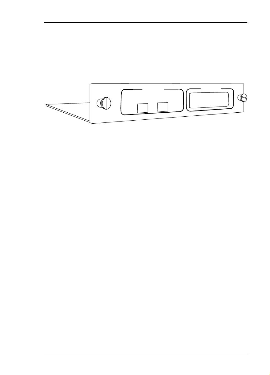
Physical Description
The FXS+ is an option module which plugs into the
option slot in the rear of the TSU 100; see Figure 1-1.
Chapter 1. Introduction
DUAL FXS
PORT X.1
PORT X.2
PORT X.3
Figure 1-1
FXS+ Dual Voice Option Module
The FXS+ rear panel includes a plastic plug over a cutout
for additional connectors. This allows a plug-on board
to be added to the FXS+ module. The PORT X.3
indication is linked to the port numbering philosophy of
the TSU 100 product family. The X represents the slot
number, and the .3 indicates the port number. For
the TSU 100 application, there is only one option slot.
Therefore the port designations for the two FXS voice
ports will be 1.1 and 1.2. If added, the plug-on board
port designation would be 1.3 and 1.4. These port
numbers will appear in the front panel LCD menu
displays.
61200.080L1-1 FXS+ Dual Voice Option Module 5
Page 10

Chapter 1. Introduction
6 FXS+ Dual Voice Option Module 61200.080L1-1
Page 11

UNPACK AND INSPECT
Carefully inspect the FXS+ Dual Voice option module for
any shipping damages. If damage is suspected, file a
claim immediately with the carrier and then contact
ADTRAN Customer Service. If possible, keep the
original shipping container for use in shipping the FXS+
module back for repair or for verification of damage
during shipment.
Shipped by ADTRAN
Chapter 2. Installation
Chapter 2
Installation
The following items are included in the ADTRAN
shipment:
• FXS+ Dual Voice option module
• User Manual
(to be inserted into main TSU 100/600 User Manual)
Provided by Customer
The customer must provide a cable for connection to the
station.
61200.080L1-1 FXS+ Dual Voice Option Module 7
Page 12

Chapter 2. Installation
INSTALLING THE FXS+ DUAL VOICE OPTION MODULE
Determine Revision Level of TSU 100 / TSU 600
FXS+ Dual Voice Module (Software Revision K and
above) can only be fully supported in TSU 100 units of
Software Revision L (and later) and TSU 600 units of
Software Revision F (and later). To determine the
software revision in the TSU, follow these steps:
1. Power the TSU On.
2. Using the front panel keypad, select Main menu item
3 (UTIL) which gives you the Utility menu.
3. From the Utility menu, select menu item 5 (Software
Revision).
4. The unit will display the revision of the operating
software.
If the card is to be installed in a TSU 100 or TSU 600
with an earlier software revision, ADTRAN recommends
that the TSU first be upgraded to the most recent
revision to ensure proper operation with the FXS+. For
assistance with software revision upgrades, please
contact ADTRAN Technical Support at
1-800-726-8663.
Before installing the module, check the back panel for the
presence or absence of a Hot Replaceable label on the back
panel
Modules
8 FXS+ Dual Voice Option Module 61200.080L1-1
With
Hot Replaceable Label on Back Panel
For ease of replacement, power to the TSU 100/600 may
be On when installing or removing the FXS+ Dual Voice
option module with a Hot Replaceable label on the back
panel .
Page 13

Chapter 2. Installation
Modules
Without
Power to the TSU 100/600 must be Off when installing
or removing the FXS+ Dual Voice option module without
a Hot Replaceable label on the back panel.
Hot Replaceable Label on Back Panel
Placement of the Option Module
Figure 2-1 represents the action required for proper
placement of the option module.
1. Remove cover plate from the TSU 100/600 rear
panel.
2. Slide option module into the rear panel until it is
positioned firmly against the front of the TSU 100/60 0.
3. Fasten thumbscrews at both edges of the option
module.
TSU 100/600
Cover Plate
Option Module
Figure 2-1
Installing Option Module
Power Connection
Each FXS+ module derives power from the base TSU
100/600 unit. Power to the TSU 100/600 is supplied by a
captive eight-foot power cord.
61200.080L1-1 FXS+ Dual Voice Option Module 9
Page 14

Chapter 2. Installation
Wiring
1, 2, 3, 6, 7, 8 UNUSED -
The FXS+ Dual Voice option module offers two connectors for an analog voice interface. The connector is
universal and accepts either an RJ-45 (8 Pin) or an RJ-11
(6 pin modular plug). The pinout is given in Table 2-A.
The required wiring connection is:
Connector Type (USOC) = RJ-45
Part number = AMP # 555164-1
Table 2-A
2-Wire Voice Pinout Connection
PIN NAME DESCRIPTION
5 TIP TIP lead of 2-wire interface
4 RING Ring lead of 2-wire interface
Pins used to mate with the FXS+ connector are as
follows:
RJ-11 Tip pin 4
Ring pin 3
RJ-45 Tip pin 5
Ring pin 4
10 FXS+ Dual Voice Option Module 61200.080L1-1
Page 15

POWER UP TESTING AND INITIALIZATION
The FXS+ option module executes an abbreviated self
test during the power up sequence, as described in the
TSU 100/600 manual. No initialization input is
required. Any previously configured setting for the
FXS+ is restored automatically upon power up.
Successful Self T est
The green OK LED, located with the Module LEDs on
the front panel, illuminates when a successful self test is
completed and the configuration is successfully restored.
See the section Front Panel Operation in the TSU 100/600
User Manual.
Failed Self T est
If the FXS+ module fails one or more of the self tests a
message is displayed in the LCD during power up. See
TSU 100/600 User Manual. Specific failures of the FXS+
module are identified in the appendix FXS+ Failure
Messages in this manual.
Chapter 2. Installation
Operation Alarms
The red ALARM LED with the Module LEDs on the front
panel illuminates when an alarm condition is detected.
Configuration of TX Level (TLP)
For any installation where the analog channel (DS0)
terminates within the Public Switched Telephone
Network, the TX LVL should be set to +3 dBm. For
point-to-point applications where the channel terminates
in other customer equipment, any TX LVL may be used.
A +3 dBm TLP setting attenuates the analog signal
by 3 dB.
61200.080L1-1 FXS+ Dual Voice Option Module 11
Page 16

Chapter 2. Installation
WARRANTY AND CUSTOMER SERVICE
ADTRAN will replace or repair this product within five
years from the date of shipment if the product does not
meet its published specifications or if it fails while in
service. For detailed warranty, repair, and return
information refer to the ADTRAN Equipment Warranty
and Repair and Return Policy Procedure.
Return Material Authorization (RMA) is required prior to
returning equipment to ADTRAN.
For Service, RMA requests, or more information, contact
one of the numbers found at the end of this manual.
12 FXS+ Dual Voice Option Module 61200.080L1-1
Page 17

OVERVIEW
Chapter 3. Operation
Chapter 3
Operation
The FXS+ module is controlled as part of the TSU
100/600 using the same methods as described in the
user manual.
See the TSU 100/600 User Manual for descriptions of
front panel indicators and buttons.
Menu Structure
When an option module is installed in the TSU
100/600, the unit adds it to the list of available options
under the Port menu items. These menu items are
shown in bold italics in the limited overview of the TSU
100 menu shown in Figure 3-1. (The appendix of the
TSU 100 User Manual contains a complete menu diagram.)
Menu Operation
An option module must be selected from the listing in
one of the Port menu options before any option module
menus are applicable. With the cursor on one of the
Port menu items, press Enter to display a list of the
currently installed option modules. To activate menus
for the FXS+ option module, scroll through the list to
display X.1 FXS+ and press Enter.
61200.080L1-1 FXS+ Dual Voice Option Module 13
Page 18

Chapter 3. Operation
Once the option module is selected, the FXS+ menus
appear as a subset of, and operate the same as, menus
for the TSU 100/600. With the cursor on one of the
TSU 100/600 four main menu choices press Enter or a
menu number to display the first two submenu items.
Use the up and down Arrows to place the cursor on the
desired item and press Enter to display the first two
submenu choices.
TSU 100
MAIN MENU
1)STATUS
2)CONFIG
3)UTIL
4)TEST
1)NETWORK (NI)
2)UNIT
3)MAP XCHNG
4)MAP IN USE A (B)
5)DS0 MAP A
6)DS0 MAP B
7)PORT CONFIG
1)NETWORK TESTS
2)RUN SELF TEST
3)PORT TEST
4)CANCEL TEST
1)NI PERF REPORTS
2)NI ERRORS
3)ACTIVE ALARMS
4)VIEW HISTORY
5)PORT STATUS
1)ENTER PASSCODE
2)TIME/DATE
3)FACTORY RESTORE
4)REINIT UNIT
5)UNIT ID
6)SOFTWARE REV
7)PORT UTIL
Figure 3-1
TSU 100 Main Menu
14 FXS+ Dual Voice Option Module 61200.080L1-1
Page 19

FXS+ MENU ITEMS
The FXS+ menus are accessed from, and operated the
same as, menus for the TSU 100/600. The FXS+ items
are submenu choices of the TSU 100/600 four main
menus, as shown in Figure 3-1. For information on
Factory Restore and Run Self Test see TSU Features Used
With FXS+ Options in this chapter.
The FXS+ menu items are discussed in the following
pages. These items are:
• Port Status
• Port Configuration
• Port Utility
• Port Test
Port Status
Port Status, a submenu of TSU 100/600 Main menu
item Status, displays active status information about the
FXS+ interface.
Chapter 3. Operation
When Port Status is displayed, place the cursor on it and
press Enter to display the first available port. See Figure
3-2. Scroll to select 1.1 FXS+ and press Enter to activate
either of the following submenus:
• 2W STATUS (2-Wire Status)
• VIEW SIG BITS (View Signaling Bits)
1)STATUS
1)NI PERF REPORTS
2)NI ERRORS
3)ACTIVE ALARMS
4)VIEW HISTORY
5)PORT STATUS
1.1 FXS
2W STATUS
+
VIEW SIG BITS
Figure 3-2
Port Status Submenus
61200.080L1-1 FXS+ Dual Voice Option Module 15
Page 20

Chapter 3. Operation
2W STA TUS (2-Wire Status)
There are three information fields, Busy, Ringing, and
MW (message waiting). See Figure 3-3. An asterisk (*)
indicates an item is active.
Figure 3-3
2-Wire Status Display
Busy
An asterisk is present if loop current is flowing through
the 2-wire circuit.
Ringing
An asterisk is present if ringing voltage is being applied
to the 2-wire circuit from the ring-generator on the FXS+
option module.
Message Waiting (MW)
An asterisk is present if the card is in the messagewaiting mode and is receiving commands from the far
end FXO+ to turn on the message-waiting light
VIEW SIG BITS (View Signaling Bits)
View Sig Bits is used to view the status of the RX and TX
signaling bits in the DS-1 stream. See Figure 3-4. The
status of both the A and B bits is displayed.
Figure 3-4
View Signaling Bits Display
16 FXS+ Dual Voice Option Module 61200.080L1-1
Page 21

PORT CONFIG (Port Configuration)
Port Configuration, a submenu of TSU 100/600 main
menu item Configuration, is used to configure the FXS+
option module. The following submenu items are used
to configure the parameters:
• MODE
• RX LVL (TLP)
• TX LVL (TLP)
• FAULT RESP
• TANDM OPTIONS
- Supervision
- Dial Tone
- Loop Rev Bat
- Ring Back
When Port Configuration is displayed, place the cursor
on it and press Enter to activate. Scroll to display the
port to be configured and activate with Enter. See
Figure 3-5.
Chapter 3. Operation
The unit displays the first of five submenu items. Table
3-A identifies the available selections for Port Configuration. Continue with standard operating procedures.
1)MODE
2)CONFIG
7)PORT CONFIG
1.2 FXS+
2)RX LVL (TLP)
3)TX LVL (TLP)
4)FAULT RESP
5)TANDM OPTIONS
Figure 3-5
Port Configuration Submenus
61200.080L1-1 FXS+ Dual Voice Option Module 17
Page 22

Chapter 3. Operation
Port Configuration Menu Items and Their Choices
Mode
Mode sets the type of 2-wire to T1 signaling and supervision to be used. Choices include:
• FXS_LS
This mode sets the port to use FXS loop-start type
signaling on the T-Span and loop-start supervision on
the analog 2-wire interface. This mode supports farend disconnect by removing tip-ground during the call
if signaled to do so over the T-span. When used with
an ADTRAN FXO+, this feature allows line-current
drop-outs to be passed on to equipment connected to
the FXS+ 2-wire port. Ringing cadence will follow that
provided over the T-span or detected by the FXO port
at the far-end.
• FXS_LSMW
This mode operates as FXS-LS but with the additional
feature of being able to illuminate the message-waiting
light on a message-waiting telephone if used in
conjunction with an ADTRAN FXO+ on the far end.
This feature requires the T-span to be operated on ESF
framing. When any port uses this mode in a slot,
ringing is scheduled to a common two second on, four
second off cadence, for all ports in that slot.
• FXS_GS
This mode set the port to use FXS ground start on the
T-span and ground-start supervision on the analog
2-wire interface. Ground start operation is often used
with trunk interfaces to PBX and key systems to
prevent glare conditions. Ringing cadence will follow
that provided over the T-span or detected by the FXO
port at the far-end.
• TANDEM_LS
This mode sets the port to use E&M signaling on the
T-Span and loop-start supervision on the analog
2-wire interface. When using this mode, line-current
drop-out for 500 ms is provided when a call terminates and the far-end hangs up. This may be useful
for voice-mail or modem systems that need far-end
18 FXS+ Dual Voice Option Module 61200.080L1-1
Page 23

Chapter 3. Operation
disconnect supervision. This mode also requires other
options to be selected. These options are: supervision, dial tone, loop reverse battery, and ringback.
These options are described in detail elsewhere.
Ringing cadence for incoming calls is two seconds on,
four seconds off.
• TANDEM_GS
This mode sets the port to use E&M signaling on the
T-Span and ground start supervision on the analog
2-wire interface. Ground-start operation is often used
with trunk interfaces to PBX and key systems to
prevent glare conditions. Appropriate TANDEM
options must be chosen in this mode as described for
TANDEM_LS. Ringing cadence for incoming calls is
two seconds on, four seconds off.
• PLAR
This mode sets the port to use PLAR signaling on the
T-span and loop-start supervision on the analog
2-wire interface. This mode is used to provide a pointto-point hot line, so that when one telephone is lifted
off-hook, the telephone at the other end rings until it
is also picked up. When both ends are off-hook, a
direct point-to-point connection is established.
Ringing cadence is two seconds on, four seconds off.
RX L VL (TLP) (Receive Level/Transmit Level Point)
RX LVL (TLP) sets the RX direction transmission level
points (TLP). The TLP is indicated in dBm and the
relative loudness is indicated by a bar graph display.
Settings change immediately as the bar graph is scrolled.
Choice range:
• –8Bm to 0dBm, in 1dB steps
TX L VL (TLP) (Transmit Level/T ransmit Level Point)
TX LVL (TLP) sets the TX direction transmission level
points (TLP). The TLP is indicated in dBm and the
relative loudness is indicated by a bar graph display.
Settings change immediately as the bar graph is scrolled.
Choice range:
• +3 dBm to –5 dBm, in 1dB steps
61200.080L1-1 FXS+ Dual Voice Option Module 19
Page 24

Chapter 3. Operation
Fault Resp (Fault Response)
Fault Resp is used to set the 2-wire response to a carrier
alarm. For a network alarm, the ground start 2-wire
trunk would appear busy if Fault Resp is set to seized. If
set to normal, no seizure of a ground start trunk occurs.
Choices include:
• Normal
• Seized
T andm Options (Tandem Options)
Some options are valid only when operating in the
tandem mode. These options are provided below.
• Supervision
Supervision sets the supervision method used when
the card is configured to operate in the Tandem mode.
Choices include:
- Immediate
- Wink
• Dial Tone
Dial Tone is used to enable or disable the on-board
dial tone generation when the FXS+ is operating in the
tandem mode. When the on-board dial tone generation is enabled, the dial tone will turn off after a five
second time-out.
Choices include:
- Enabled
- Disabled
• Loop Reverse Battery
This option causes the polarity of tip and ring to be
reversed when the far-end answers and the FXS+ card
is set to TANDEM_LS mode. This provides answer
supervision to the 2-wire port.
Choices include:
- Enabled
- Disabled
20 FXS+ Dual Voice Option Module 61200.080L1-1
Page 25

Chapter 3. Operation
• Ringback
This option generates ringback tone towards the
T-span when enabled and the FXS+ card is in one of
the Tamden modes. This may be needed on some
cases when the network does not provide ringback
tone.
Choices include:
- Enabled
- Disabled.
Port Configuration Menu Items/Parameters Summary
Table 3-A provides a summary of the Port Configuration
menu items and their parameters.
Port Configuration Parameters
MENU ITEM PARAMETER CHOICES
MODE FXS_LS FXS_LSMW , FXS_GS
T ANDEM_LS, TANDEM_GS, PLAR
Table 3-A
RX L VL (TLP) -8 dBm to 0 dBm, 1 dB steps *(-6 dBm)
TX L VL (TLP) +3 dBm to -5 dBm, 1 dB steps *(+1 dBm)
F AULT RESP *Normal, Seized
Supervision *Immediate, Wink
Dial T one Enable, *Disabled
Loop Rev Bat *Disabled, Enabled
Ringback *Disabled, Enabled
*Factory Default
61200.080L1-1 FXS+ Dual Voice Option Module 21
Page 26

Chapter 3. Operation
PORT UTIL (Port Utility)
Port Utility, a submenu of the TSU 100/600 Main menu
item Utilities (UTIL) displays the current software
information for each port installed in the unit. This
information is required when requesting assistance
from ADTRAN Customer Service or when updates are
needed.
When Port Utility is displayed, place the cursor on it
and press Enter to display the first available port. See
Figure 3-6.
1)ENTER PASSCODE
2)TIME/DATE
3)FACTORY RESTORE
3)UTIL
4)REINIT UNIT
5)UNIT ID
6)SOFTWARE REV
7)PORT UTIL
1.1 FXS+
1)SW REVISION
2)COMMAND MODE
Figure 3-6
Port Utility Submenus
Display 1.1 FXS+ (scroll to display if necessary), and
press Enter. The unit displays the option module
name and the software version installed.
The submenu Port Utility contains a second option,
2)CMD Mode, for the FXS+ module. This option is
reserved for factory use only.
Press Cancel to exit or select another port.
22 FXS+ Dual Voice Option Module 61200.080L1-1
Page 27

Port Test
Chapter 3. Operation
Port Test, a submenu of the TSU 100/600 Main menu
item Test, activates tests of the selected data ports.
Selecting the FXS+ displays tests available for this option
module. See Figure 3-7 and Table 3-B.
4)TEST
1)NETWORK TESTS
2)RUN SELF TEST
3)PORT TEST
4)CANCEL TEST
1.1 FXS+
1)1 KHZ TONE
2)VIEW SIG BITS
3)SET TX SIGNAL
4)SET 2W OUTPUT
Figure 3-7
Port Test Submenus
When Port Test is displayed, place the cursor on it and
press Enter to display the first available port. Scroll to
select 1.1 FXS+ and press Enter to activate the following
submenu items:
• 1 kHz Tone
• View Sig Bits
• Set TX Signal
• Set 2W Output
These items are discussed in the following pages.
1 kHz T one
This test injects a 1 kHz sine wave either toward the far
end (TX direction toward the T1 network) or toward the
near end (the 2-wire interface on the option module).
This tone may be used for testing or relative level
measurements. When 1 kHz Tone is enabled, ringback
and dial tone for other channels on the slot are suspended.
Choices include:
•Off
• Near
• Far
61200.080L1-1 FXS+ Dual Voice Option Module 23
Page 28

Chapter 3. Operation
VIEW SIG BITS (View Signaling Bits)
View Sig Bits is used to view the status of the RX and TX
signaling bits in the DS-1 stream. See Figure 3-8. The
status of both the A and B bits is displayed.
Figure 3-8
View Signaling Bits Display
SET TX SIGNAL (Set Transmit Signal)
Set TX Signal allows the A and B signal bits in the TX
direction to be forced to a desired state for test.
SET 2-W OUTPUT (Set 2-Wire Output)
Set 2W Output allows the 2-wire voice interface output
to be forced to a desired state for test.
Table 3-B
Port Test Parameters
MENU ITEM PARAMETER CHOICES
1 kHz Tone Off, Near, Far
View Sig Bits Display only
Set TX Signal Off, A=0 B=0, A= B=0, A= B=1, A=1 B=1
Set 2W Output Off, Disabled, Tip Open, Active, Ringing
24 FXS+ Dual Voice Option Module 61200.080L1-1
Page 29

TSU FEATURES USED WITH FXS+ OPTIONS
In addition to the FXS+ menu items, two additional
menu items of the TSU 100/600 may be operated in
conjunction with the FXS+ option module. These are
Factory Restore and Run Self Test.
Factory Restore
Factory Restore, a submenu of the TSU 100/600 Main
menu item Utilities (UTIL), restores the factory installed
default setting for all FXS+ option module parameters.
When Factory Restore is displayed, place the cursor on it
and press Enter. The unit is restored to preset factory
defaults and returns to the main TSU 100/600 menu.
The factory default for port configuration parameters is
shown in Table 3-A.
Run Self T est
Run Self Test, a submenu of the TSU 100/600 Main
menu item Test, executes both the FXS+ internal test
and the TSU 100/600 internal test. The results of the
self test are displayed in the LCD. See the TSU 100/600
User Manual for additional information on Self Test.
Chapter 3. Operation
When Run Self Test is displayed, place the cursor on it
and press Enter to execute the test. The unit continuously changes the display in the LCD window until all
test results are shown.
61200.080L1-1 FXS+ Dual Voice Option Module 25
Page 30

Chapter 3. Operation
26 FXS+ Dual Voice Option Module 61200.080L1-1
Page 31

Appendix A. 2FXS+ Failure Messages
FXS+ Failure Messages
FAILURE MESSAGES AT POWER-UP
The following messages indicate a probable component
failure on the FXS+ Module:
E01 - EPROM CS EPROM checksum error
E02 - RAM ERR Static RAM error
E03 - RNG FQ HI Ring generator frequency too high
Appendix A
E04 - RNG FQ LO Ring generator frequency too low
E05 - NO RING No ringing from ring generator
E06 - TEST FAIL Self test could not finish
E07 - RINGING Ringing detected incorrectly
E10 - SIGNALING Failure of signal bit transmission
FXS+ ALARM MESSAGES
No alarms are specified for the FXS+ Dual Voice option
module.
61200.080L1-1 FXS+ Dual Voice Option Module 27
Page 32

Appendix A. 2FXS+ Failure Messages
28 FXS+ Dual Voice Option Module 61200.080L1-1
Page 33

Appendix B. Signaling States Vs. Mode of Operation
Appendix B
Signaling States
SIGNALING STATES VS. MODE OF OPERA TION
The four tables in this appendix describe the signaling
states for voice card and the DS-1 PCM stream.
Ground start signaling is not used in PLAR mode. See
Table B-A.
Table B-A
PLAR Mode
FXS+ FXS+
2W Input RX A RX B TX A TX B 2W Output
Loop Open X X 1 1 -
Loop Closed X X 0 0 -
Loop Open 1 1 1 1 N o Ringing
Loop Open 0 X 1 1 Ringing
Loop Closed 0 X 0 0 No Ringing
The A and B signal bit states on the DS-1 signal are as
follows:
0 = logic 0 is the DS-1 stream
1 = logic 1 is the DS-1 stream
X = value is not significant
Loop Open = phone on-hook
Loop Closed = phone off-hook
61200.080L1-1 FXS+ Dual Voice Option Module 29
Page 34

Appendix B. Signaling States Vs. Mode of Operation
Ground start signaling provides its own tip ground in
response to ring ground in the Tandem Mode. See
Table B-B.
Table B-B
Tandem Mode
FXS+
2W Input
(Outgoing call from FXS+)
Loop Open
Loop Closed
Loop Closed
Loop Closed
Loop Closed
(Incoming call to FXS+)
Loop Open
Loop Closed
Loop Closed
RX A RX B TX A
0
0
1
0
1
0
1
1
The A and B signal bit states on the DS-1 signal are as
follows:
0 = logic 0 is the DS-1 stream
1 = logic 1 is the DS-1 stream
X = value is not significant
Loop Open = phone on-hook
Loop Closed = phone off-hook
FXS+
2W Output
TX B
0
X
X
X
X
X
X
0
X
0
X
1
0
1
1
1
1
1
1
1
1
0
0
1
—
—
Dial Tone
-
Ringing
Answers
Switch to FXS+
Condition
Idle
Idle
Wink
Wink Done
Answer Far End
Idle
Far end off hook
Far end off hook
30 FXS+ Dual Voice Option Module 61200.080L1-1
Page 35

Appendix B. Signaling States Vs. Mode of Operation
See Tables B-C and B-D for descriptions of FXS mode for
signaling states.
Table B-C
FXS+ Mode (Loop-Start)
F X S FXS+
2W Input RX A RX B TX A TX B 2W Output
(Outgoing call from FXS+)
Loop Open X 1 0 1 No Ringing (Idle)
Loop Closed X 1 1 1 N o Ringing
(Incoming call to FXS+)
Loop Open X 0 0 1 Ringing
Loop Closed X 0 1 1 No Ringing
The A and B signal bit states on the DS-1 signal are as
follows:
0 = logic 0 is the DS-1 stream
1 = logic 1 is the DS-1 stream
X = value is not significant
Loop Open = phone on-hook
Loop Closed = phone off-hook
61200.080L1-1 FXS+ Dual Voice Option Module 31
Page 36

Appendix B. Signaling States Vs. Mode of Operation
Table B-D
FXS+ Mode (Ground Start)
FXS+ FXS+
2W Input RX A RX B TX A TX B 2W Output
(Outgoing call from FXS+)
No Ring Gnd
or
Loop Open 1 1 0 1 Idle
Ring Gnd 1 1 0 0 No Tip Gnd
Ring Gnd
or
Loop Closed 0 1 1 1 Tip Gnd
Loop Open 0 0 0 1 Tip Gnd & No Ringing
Loop Closed 0 0 1 1 Tip Gnd & Ringing
( Incoming call to FXS+)
(IDLE) 1 X - - No Tip Gnd & No Ringing
0 1 - - Tip Gnd & No Ringing
Loop Open 0 0 0 1 Tip Gnd & Ringing
Loop Closed 0 0 1 1 Tip Gnd & No Ringing
The A and B signal bit states on the DS-1 signal are as
follows:
0 = logic 0 is the DS-1 stream
1 = logic 1 is the DS-1 stream
X = value is not significant
Loop Open = phone on-hook
Loop Closed = phone off-hook
32 FXS+ Dual Voice Option Module 61200.080L1-1
Page 37

Index
Product Support Information
Presales Inquiries and Applications Support
Please contact your local distributor, ADTRAN Applications Engineering, or ADTRAN Sales:
Applications Engineering (800) 615-1176
Sales (800) 827-0807
Post-Sale Support
Please contact your local distributor first. If your local
distributor cannot help, please contact ADTRAN Technical Support and have the unit serial number available.
Technical Support (800) 726-8663
Repair and Return
If ADTRAN Technical Support determines that a repair is
needed, Technical Support will coordinate with the
Return Material Authorization (RMA) department to
issue an RMA number. For information regarding
equipment currently in house or possible fees associated
with repair, contact RMA directly at the following
number:
RMA Department (205) 971-8722
Identify the RMA number clearly on the package (below
address), and return to the following address:
ADTRAN, Inc.
RMA Department
901 Explorer Boulevard
P. O. Box 070020
Huntsville, Alabama 35807
RMA # _____________
61200.080L1-1 FXS+ Dual Voice Option Module 29
Page 38

NOTICE
This FXS+ module (Software Revision L and later) includes far-end disconnect and analog message-waiting features when used with an ADTRAN FX0+
module. The configuration menu structure has been modified to accommodate these new features. If T -W atch is used to configure this card, version 3.0
or later is needed. If you do not have version 3.0 or later , you may upgrade
your older revision to the latest by downloading the T -W atch upgrade fr om
the ADTRAN world-wide web site, http://www .adtran.com. (Select Suppor t
& Ser vices screen, then select Software Update).
If T-Flash is used to upgrade the TSU 100/600, use version 1.1 or later . If T Flash 1.0 is used, it will be necessar y to execute Cancel All Tests fr om the T est
menu when T -Flash has completed its upgrade.
This addendum suppor ts the FXS+ Dual Voice Module & FXS+ Dual Voice Plug-
On Board User Manual, PN 61200.080L1-1C.
61200.080L1-10B
November 1995
 Loading...