

Page 1

Dual DSU-DP
Option Module & Plug-On Board
Option Module PN 1200127L1#HS
Plug-On Board PN 1200128L1
USER MANUAL
61200.128L1-1A
April 1996
Page 2

901 Explorer Boulevard
P.O. Box 070020
Huntsville, AL 35807
Phone: (205) 971-8000
Fax: (205) 971-8699
© 1996 ADTRAN, Inc.
All rights reserved.
Printed in USA.
Page 3

FEDERAL COMMUNICATIONS COMMISSION
RADIO FREQUENCY INTERFERENCE STATEMENT:
This equipment has been tested and found to comply with the limits for a Class
A digital device, pursuant to Part 15 of the FCC Rules. These limits are designed
to provide reasonable protection against harmful interference when the equipment is operated in a commercial environment. This equipment generates, uses,
and can radiate radio frequency energy and, if not installed and used in
accordance with the instruction manual, may cause harmful interference to radio
frequencies. Operation of this equipment in a residential area is likely to cause
harmful interference in which case the user will be required to correct the
interference at his own expense.
WARNING:
Change or modifications to this unit not expressly approved by the party
responsible for compliance could void the user’s authority to operate the
equipment.
Page 4

Table of Contents
Page 5

Table of Contents
Table of Contents
Chapter 1 Introduction
Product Overview............................................................................................... 1
DDS Overview ............................................................................................. 3
Switched 56 Overview ................................................................................ 3
Chapter 2 Installation .................................................................................. 5
Unpack and Inspect ........................................................................................... 5
Shipped by ADTRAN .................................................................................. 5
Adapter Cables ............................................................................................ 5
Provided by Customer ................................................................................ 5
Installing the Option Module ............................................................................ 6
Placement of the Option Module ............................................................... 6
Power Connection....................................................................................... 6
Attaching the Plug-On Board ...................................................................... 7
Rear Panel ........................................................................................................... 8
DTE Data Connection ........................................................................................ 9
Main DTE Data Connection/Primary DTE ....................................................... 9
Configuration ................................................................................................... 11
Configuration Methods ............................................................................. 12
AT Commands .......................................................................................... 12
V.25 bis Commands.................................................................................. 13
SDLC Option ...................................................................................... 13
Character Format ........................................................................ 13
Command Structure ................................................................... 13
Bi-Sync Option ................................................................................... 14
Character Format .........................................................................14
Command Structure ....................................................................14
Asynchronous Option ........................................................................ 14
Character Format .........................................................................14
Command Structure ....................................................................14
Command Descriptions ..................................................................... 14
Syntax and Possible Responses ......................................................... 15
CIC (Connect Incoming Call) .................................................... 15
CNL (Configuration Local) ........................................................ 16
CNR (Configuraton Remote) ...................................................... 16
Switched 56 Operation ...................................................................... 17
CRN (Call Request with Number)...............................................17
CRS (Call Request Using Stored Number)..................................17
61200.128L1-1 Dual DSU-DP User Manual i
Page 6

Table of Contents
DIC (Disregard Incoming Call) .................................................. 18
PRN (Program Number) ............................................................. 18
RLN (Request List of Numbers) ................................................. 18
Chapter 3 Operation
Overview ........................................................................................................... 19
Menu Structure.......................................................................................... 19
MenuOperation ......................................................................................... 21
Chapter 4 Configuration
Configuration Overview .................................................................................. 23
Local and Remote Configuration ............................................................. 23
Configuration Menu .................................................................................. 23
Configuring Network Options ........................................................................ 25
Network Options ...................................................................................... 25
Network Rate............................................................................................. 25
Network Address....................................................................................... 27
Remote Configuration Option .................................................................. 28
Network Type............................................................................................ 29
Configuring DTE Options ............................................................................... 30
DTE Rate.................................................................................................... 30
Data Format............................................................................................... 32
DTE Command Option ............................................................................ 33
Transmit Clock.......................................................................................... 34
CS Options ................................................................................................ 36
Anti-Stream ..................................................................................................... 39
CD Options ............................................................................................... 41
TR Options ................................................................................................ 42
SR Options ................................................................................................ 43
Test Options ..................................................................................................... 44
Test Timeout ............................................................................................. 44
Remote Digital Loopback ......................................................................... 45
Configuring Dial Options ................................................................................ 46
Phone Number .......................................................................................... 46
Auto Answer .............................................................................................. 47
Manual Command ........................................................................................... 48
Chapter 5 Dialing
Dialing Overview .............................................................................................. 51
1. No Call Active ......................................................................... 52
2. Call Is Active ........................................................................... 53
3. Receiving an Incoming Call with Auto Answer Disabled...... 53
ii DSU DP User Manual 61200.128L1-1
Page 7

Table of Contents
Chapter 6 Testing & Troubleshooting
Test Overview ................................................................................................... 55
Initiating a Test.......................................................................................... 56
DSU-DP Test Operation ............................................................................ 57
Tests Using the TEST Pattern Generator........................................... 57
Remote Test ........................................................................................ 60
Troubleshooting ............................................................................................... 61
Messages from the DSU/CSU .................................................................. 61
Troubleshooting New Installs................................................................... 62
Test Sequence for Troubleshooting New Installs
or Existing Circuits ............................................................................ 63
Local Unit Diagnostics ..................................................................................... 64
DTE and NET ............................................................................................ 65
Test Description ................................................................................. 65
Test Purpose ....................................................................................... 65
Initiating ............................................................................................. 66
Interpreting Test Results .................................................................... 66
NET Only (RT) .......................................................................................... 67
Test Purpose ....................................................................................... 67
Initiating ............................................................................................. 67
Interpreting Test Results .................................................................... 68
DTE Only................................................................................................... 69
Test Purpose ....................................................................................... 69
Initiating ............................................................................................. 70
Interpreting Test Results .................................................................... 70
DTE with Test Pattern ............................................................................... 71
Test Purpose ....................................................................................... 71
Initiating ............................................................................................. 71
Interpreting Test Results .................................................................... 72
TP to Network ........................................................................................... 73
Test Purpose ....................................................................................... 73
Initiating ............................................................................................. 73
Interpreting Test Results .................................................................... 74
Exit Test ..................................................................................................... 74
Remote Unit Diagnostics ................................................................................. 75
Test Purpose ....................................................................................... 76
Initiating ............................................................................................. 76
Test Results ........................................................................................ 76
Interpreting Test Results .................................................................... 76
61200.128L1-1 Dual DSU-DP User Manual iii
Page 8

Table of Contents
Chapter 7 Status Selection
STATUS Display ............................................................................................... 77
DSU Operational Status ............................................................................ 78
DDS Network Status ................................................................................. 78
Network Rate............................................................................................. 79
DTE Rate/Mode ........................................................................................ 79
DTE Control Leads and Status ................................................................. 80
Appendix A AT Commands........................................................................ 81
Appendix B Default Configuration Profiles .............................................. 83
Default Configuration Profiles......................................................................... 83
Profile 1 ....................................................................................... 83
Profile 2 ....................................................................................... 83
Appendix C DSU to Modem Interconnect ................................................. 85
Modem Tail Circuit Application ...................................................................... 85
Appendix D EIA-232 Connector ................................................................. 87
56 and 64 kbps Application ............................................................................ 87
Appendix E DSU-DP Configuration Menu Tree ........................................ 89
Appendix F Troubleshooting Supplement................................................. 93
TSU History Buffer Alarms .............................................................................. 93
OUT OF SERVICE (OOS) ........................................................................ 93
DTE Streaming .......................................................................................... 94
When Alarms Clear ................................................................................... 94
Non-Alarm Conditions in History Buffer ........................................................ 94
OCU LB BY CO ........................................................................... 94
CSU LB BY CO ON ..................................................................... 94
DSU LB BY CO ON ..................................................................... 94
IN RDL BY FAR ........................................................................... 94
SLAVED RMT CNF ..................................................................... 94
EIA LLB ON................................................................................. 94
LOCAL TEST ON ........................................................................ 95
REMOTE TEST ON ..................................................................... 95
REMOTE CONF ON ................................................................... 95
TEST OFF .................................................................................... 95
REMOTE CONF OFF.................................................................. 95
iv DSU-DP User Manual 61200.128L1-1
Page 9

Table of Contents
Figures
Figure 1-1 Sample Point-to-Point Application for Dual DSU-DP................... 2
Figure 2-1 Installing the Option Module ....................................................... 6
Figure 2-2 Attaching the Plug-On Board........................................................ 7
Figure 2-3 DSU-DP Option Module Rear View ............................................. 8
Figure 3-1 TSU 100 Main Menu ................................................................... 20
Figure 4-1 Setting Network Rate Options .................................................... 25
Figure 4-2 Setting the Network Address ...................................................... 27
Figure 4-3 Enabling/Disabling Remote Configuration................................ 28
Figure 4-4 Setting Network Type Options ................................................... 29
Figure 4-5 DTE Rates for 56 or 64 kbps Network Rate ............................... 30
Figure 4-6 Selecting Asynchronous or Synchronous Data Format ............. 32
Figure 4-7 Selecting the DTE Command Option......................................... 33
Figure 4-8 Transmit Clock Options.............................................................. 34
Figure 4-9 Selecting CS Options .................................................................. 36
Figure 4-10 Anti-Stream Options ................................................................... 39
Figure 4-11 Selecting CD Options.................................................................. 41
Figure 4-12 Selecting TR Options .................................................................. 42
Figure 4-13 Setting SR Options ...................................................................... 43
Figure 4-14 Setting Test Timeout Option ....................................................... 44
Figure 4-15 Remote Digital Loopback ........................................................... 45
Figure 4-16 Editing Stored Phone Numbers .................................................. 46
Figure 4-17 Enabling/Disabling the Auto Answer Function.......................... 47
Figure 4-18 Manual Command....................................................................... 48
Figure 5-1 Menu Path to Initiate a Call ........................................................ 51
Figure 6-1 Normal Operation Before Initiating Loopback Test ................... 55
Figure 6-2 Initiating a Test ............................................................................ 56
Figure 6-3 Complete Test Menu ................................................................... 58
Figure 6-4 Remote Test Example.................................................................. 60
Figure 6-5 DTE & Net Test ........................................................................... 65
Figure 6-6 Initiating a DTE & Net Test ........................................................ 66
Figure 6-7 Loop Only Test ............................................................................ 67
Figure 6-8 Initiating a Net Only Test ............................................................ 67
Figure 6-9 DTE Only Test Diagram .............................................................. 69
Figure 6-10 Initiating a DTE Only Test .......................................................... 70
Figure 6-11 DTE with Test Pattern ................................................................. 71
Figure 6-12 Initiating a DTE Test with Test Pattern....................................... 72
Figure 6-13 Test Pattern Only ........................................................................ 73
Figure 6-14 Initiating a Test Using a Test Pattern ........................................... 74
Figure 6-15 V.54 RDL with Test Pattern ......................................................... 75
Figure 6-16 Initiating a Remote Test .............................................................. 76
Figure 7-1 Examples of Status Displays ....................................................... 77
61200.128L1-1 Dual DSU-DP User Manual v
Page 10

Table of Contents
Figure C-1 DSU to Modem Interconnet ......................................................... 85
Figure D-1 EIA-232 Connector ....................................................................... 87
Figure E-1 DSU-DP Configuration Menu Tree .............................................. 91
Tables
Table 2-A Pin Assignments for Primary EIA-232 Cable ............................... 9
Table 2-B Pin Assignments for Primary V.35 Cable ................................... 10
Table 2-C Configuration Methods .............................................................. 12
Table 4-A Loop Rate Commands ................................................................ 26
Table 4-B Network Address Command ...................................................... 27
Table 4-C Remote Configuration Commands............................................. 28
Table 4-D Network Type Commands .......................................................... 29
Table 4-E DTE Rate AT Commands ............................................................ 31
Table 4-F Data Format Commands ............................................................. 32
Table 4-G Transmit Clock AT Commands .................................................. 34
Table 4-H CS Options AT Commands ........................................................ 37
Table 4-I Short and Long Delays at Different Operating Speeds .............. 38
Table 4-J Anti-Stream AT Commands ........................................................ 4 0
Table 4-K CD Options AT Commands........................................................ 41
Table 4-L TR Options AT Commands ........................................................ 42
Table 4-M SR Options AT Commands......................................................... 43
Table 4-N Test Timeout AT Commands ...................................................... 44
Table 4-O Remote Digital Loopback AT Commands.................................. 45
Table 4-P AT Commands for Storing Phone Numbers .............................. 46
Table 4-Q AT Commands for Auto Answer ................................................. 47
Table 4-R Manual Commands ..................................................................... 49
Table 6-A Values for TST ERR=XXXX ......................................................... 58
Table 6-B Messages from the DSU-CSU ..................................................... 61
Table 6-C Troubleshooting New Installs ..................................................... 62
Table 6-D Test AT Commands ..................................................................... 64
Table 6-E Remote Tests and AT Commands ............................................... 75
Table A-A AT Commands ............................................................................. 81
Table A-B Test Pattern Commands.............................................................. 82
Table B-A Default Configuration Profiles .................................................... 84
vi Dual DSU-DP User Manual 61200.128L1-1
Page 11

PRODUCT OVERVIEW
The ADTRAN Dual DSU-DP provides a reliable, high
speed data connection for customer data terminal
equipment (DTE) through the ADTRAN TSU/HSU DS0
port. It provides compatibility with digital data service
(DDS), or Switched 56 network (SW56) services. The
Dual DSU-DP supports both synchronous and asynchronous data communication over the DDS or Switched 56
networks.
Chapter 1. Introduction
Chapter 1
Introduction
This unit is an all rate DSU, supporting services from 2.4
to 64 kbps including 19.2 and 38.4 kbps services. The
Dual DSU-DP may be used in either point-to-point or
multi-point circuits.
The Dual DSU-DP provides both V.35 and EIA-232
electrical and physical DTE interfaces through either an
ADTRAN HD-to-RS-232 cable (PN 1200167L2) or
ADTRAN HD-to-V.35 cable (PN 1200167L1) to accommodate a variety of applications.
In addition to DDS, the unit also supports Switched 56
(4-wire) service with dialing accomplished from either
the front panel or the DTE interface using either the AT
command set or the V.25 BIS command set. This model
is compatible with AT&T Accunet and U.S. Sprint®
SW56 type services.
61200.128L1-1 Dual DSU-DP User Manual 1
Page 12
Chapter 1. Introduction
ENTER
CANCEL
SHIFT
SHIFT
RS CS TD RD CD ALM TST
DSU III DBU
ENTER
CANCEL
SHIFT
SHIFT
RS CS TD RD CD ALM TST
DSU III DBU
ENTER
CANCEL
SHIFT
SHIFT
RS CS TD RD CD ALM TST
DSU III DBU
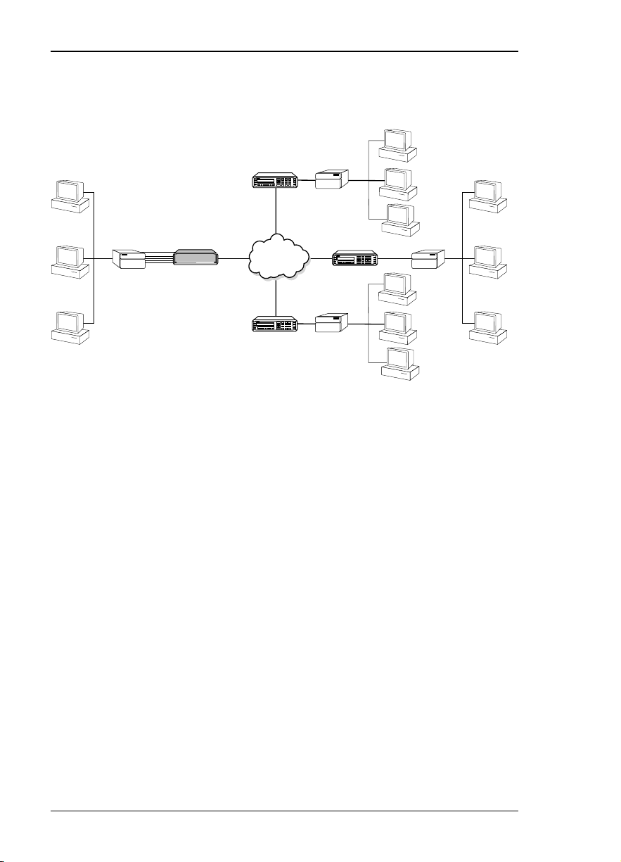
Figure 1-1 shows a sample point-to-point application for
the Dual DSU-DP.
DSU III AR
DSU III DBU
ENTER
RS CS TD RD CD ALM TST
CANCEL
Up to four
DTE ports
per module
TSU/HSU
F
DDS
Network
T1
DSU III DBU
ENTER
RS CS TD RD CD ALM TST
CANCEL
Router DSU III AR
DSU III AR
Router
C
1 2 3
DAEBF
4 5 6
7 8 9
SHIFT
SHIFT
#0
*
DSU III DBU
ENTER
RS CS TD RD CD ALM TST
CANCEL
56 kbps
C
1 2 3
DAEBF
4 5 6
7 8 9
SHIFT
SHIFT
#0
*
Router
Sample Point-to-Point Application for Dual DSU-DP
C
1 2 3
DAEBF
4 5 6
7 8 9
SHIFT
SHIFT
#0
*
Router
Figure 1-1
2 Dual DSU-DP User Manual 61200.128L1-1
Page 13

DDS Overview
Digital Data Service (DDS) is a nationwide service that
allows interconnection and transport of data at speeds
up to 64 kbps. The local exchange carriers provide the
local loop service to DDS customers and may provide
data for routing Inter-LATA to an interexchange carrier.
In DDS mode, the Dual DSU-DP supports all DDS
service rates yielding DTE rates of 2.4, 4.8, 9.6, 19.2, and
38.4 (sync or async); and 56 and 64 kbps (sync only).
An additional rate of 57.6 kbps is available in async
mode. At the service rates of 56 kbps and 64 kbps, the
unit can be configured to run slower DTE rates (async or
sync).
Switched 56 Overview
This switched Digital Data Service allows customers to
pay for data connection only for the time the circuit is
connected. The regional operating companies or
interexchange carriers provide the service to SW56
customers. In SW56 mode the Dual DSU-DP supports
DTE rates of 2.4, 4.8, 9.6, 19.2, and 38.4 (asynchronous
or synchronous), and 56 kbps (synchronous). An
additional DTE rate of 57.6 kbps is available in async
Chapter 1. Introduction
61200.128L1-1 Dual DSU-DP User Manual 3
Page 14

Chapter 1. Introduction
4 Dual DSU-DP User Manual 61200.128L1-1
Page 15

UNPACK AND INSPECT
Carefully inspect the option module or plug-on board for
any shipping damages. If damage is suspected, file a claim
immediately with the carrier and contact ADTRAN
Customer Service. If possible, keep the original shipping
container for use in shipping the Dual DSU-DP for repair
or for verification of damage during shipment.
Shipped by ADTRAN
Chapter 2. Installation
Chapter 2
Installation
The following items are included in the ADTRAN shipment:
• The Dual DSU-DP Option Module or Dual DSU-DP
Plug-On Board
• The user manual (to be inserted into the main TSU/HSU
user manual)
Adapter Cables
Two cables must be purchased separately from ADTRAN:
• PN 1200167L1 HD to V.35 (Winchester)
• PN 1200167L2 HD to RS-232 (DB25)
Provided by Customer
The customer must provide a cable for connection to the
DTE device.
61200.128L1-1 Dual DSU-DP User Manual 5
Page 16
Chapter 2. Installation
INSTALLING THE OPTION MODULE
It is not necessary to turn off the power to the TSU/HSU
when installing the option module because it is hot
swappable. The plug-on board must be attached to a hot
swappable option module if you wish to install it while the
TSU/HSU is powered on.
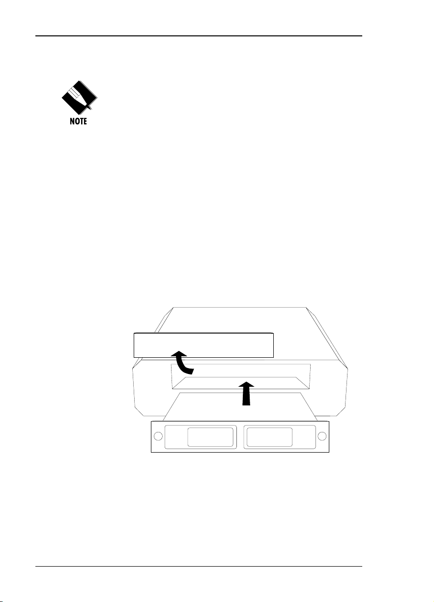
Placement of the Option Module
Figure 2-1 is representative of the action required for
proper placement of the option module. Perform the
following steps to install the option module:
1. Remove the cover plate from the TSU/HSU unit rear
panel.
2. Slide the option module into the rear panel of the
TSU/HSU unit until it is positioned firmly against the
front of the unit.
3.. Fasten the thumbscrews at both edges of the option
module.
Cover Plate
TSU/HSU
UNIT
Option Module
Figure 2-1
Installing the Option Module
Power Connection
Each option module derives power from the base TSU/
HSU unit. Power to the TSU/HSU is supplied by a captive
eight-foot power cord.
6 Dual DSU-DP User Manual 61200.128L1-1
Page 17
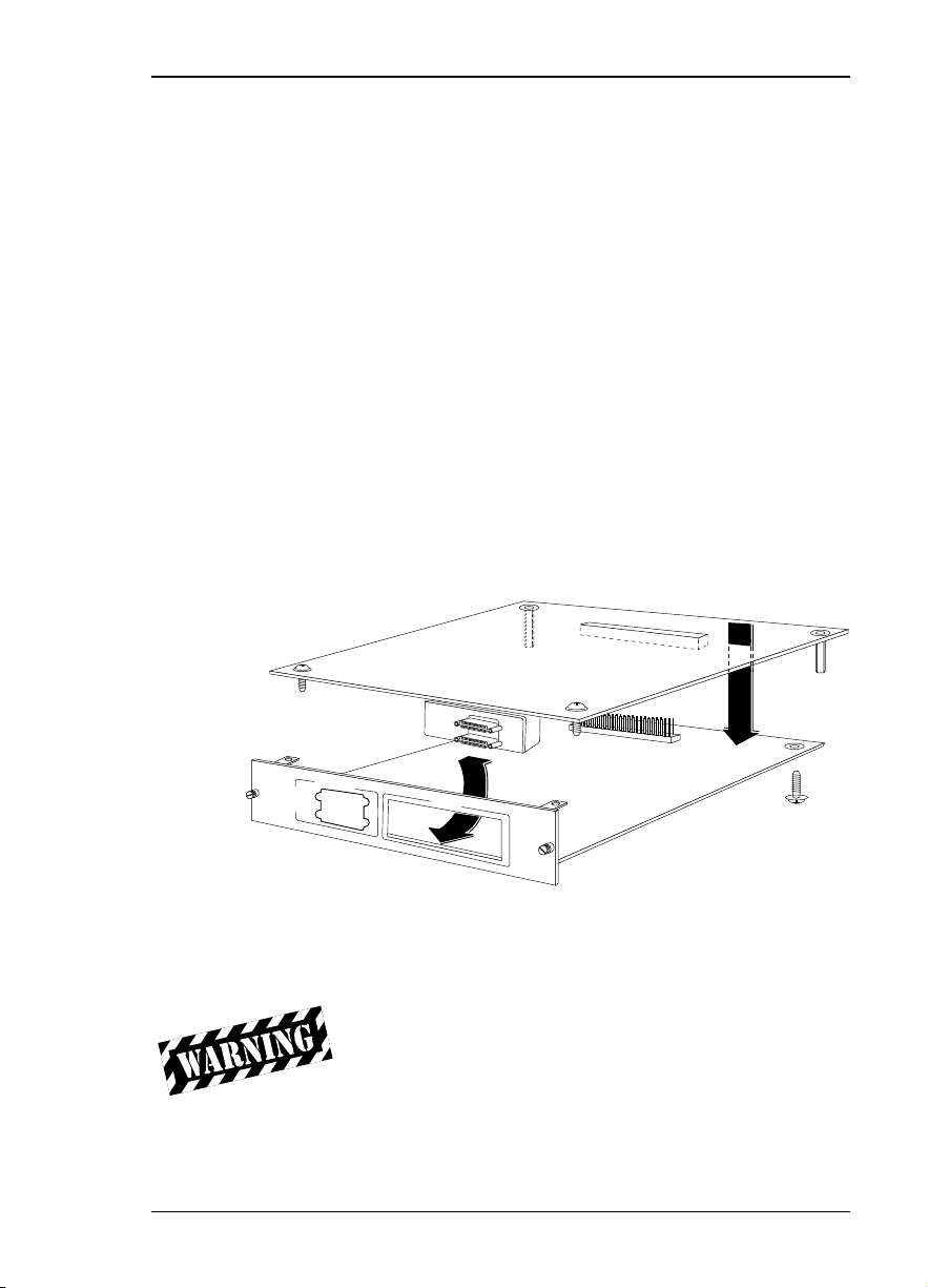
Attaching the Plug-On Board
Figure 2-2 is representative of the action required for
proper attachment of a plug-on board to the option
module. Perform the following steps to install the plugon board:
1. Hold the plug-on board above the option module.
2. Using a downward and right-to-left motion, slip the
plug-on board connector into the opening in the
option module back panel.
3. Moving the plug-on board downward, secure the
connection of the header pins at the front of the
boards.
4. Install two 4-40 screws at both front edges of the
option module.
5. Install two 4-40 screws on each of the standoffs on
the rear of the plug-on module.
Chapter 2. Installation
P
O
R
T
X
.
3
P
O
R
T
X
.4
D
U
A
L
D
S
U
-D
P
P
O
R
T
X
.
1
P
O
R
H
T
O
X
T
.
2
R
E
P
L
A
C
E
A
B
L
E
PORT X.3
Figure 2-2
Attaching the Plug-On Board
The connection of the header pins between the option module
and the plug-on board must be visually verified. Severe
damage of the equipment can result from an improper
connection.
61200.128L1-1 Dual DSU-DP User Manual 7
Page 18
Chapter 2. Installation
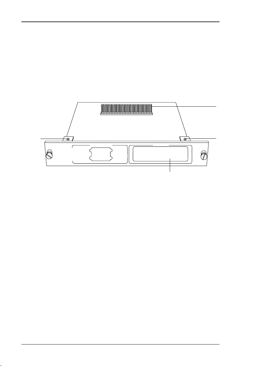
REAR PANEL
The rear panel contains two high-density subminiature
DTE connectors which provide V.35 or EIA-232 interfaces via custom cables. Pin assignments for the DTE
connections are listed in the section DTE Data Connec-
tion in this chapter. The DSU-DP rear panel is shown in
Figure 2-3.
3
2
HOT
REPLACEABLE
PORT X.1
DUAL DSU-DP
PORT X.2
1 - Cutout for plug-on board interfaces
2 - Screw receptacles for plug-on board
3 - Plug-on board header
DSU-DP Option Module Rear View
2
PORT X.3
1
Figure 2-3
8 Dual DSU-DP User Manual 61200.128L1-1
Page 19
DTE DATA CONNECTION
The DTE should be connected to either the EIA-232 DTE
cable or the CCITT V.35 DTE cable. The maximum cable
lengths recommended are 50 feet for the EIA-232, and
100 feet for the C C IT T V.35 (note: ADT RAN -adapter
cables are six feet in length). The pin assignments for the
cables are listed in Tables 2-A and 2-B.
The V.35 cable is recommended for use with data rates
above 19.2 kbps. The EIA-232 cable works up to 56 kbps
with a low capacitance cable or with the external transmit
clock option selected. The DT E rate may be configured
from the front panel or via the T-Watchª Management
Program. The DT E can operate in asynchronous or
synchronous modes.
To prevent possible radio frequency interference emissions, a
shielded cable is required.
Chapter 2. Installation
Table 2-A
Pin Assignments for Primary EI A-232 Cable
HD* Pin # Pin # EIA Description
1 1 AA Protective Ground (PG)
2 2 BA Transmit Data (TD)
3 3 BB Receive Data (RD)
4 4 CA Request to Send (RS)
5 5 CB Clear to Send (CS)
6 6 C C Data Set Ready (SR)
7 7 AB Signal Ground (SG)
8 8 CF Received Line Signal Detector (CD)
15 15 DB Transmit Clock (TC)
16 17 DD Receive Clock (RC)
18 18 - Local Loopback (LL)
20 2 0 C D Data Terminal Ready (TR)
17 2 2 CE Ring Indicator (RI)
14 24 DA External TX Clock (ETC)
19 25 - Test Indicator (TI)
* HD = High Density
61200.128L1-1 Dual DSU-DP User Manual 9
Page 20

Chapter 2. Installation
Table 2-B
Pin Assignments for Primary V.35 Cable
HD P in # P i n CCITT
1 A 10 1 Protective Ground (PG)
7 B 102 Signal G round (SG)
4 C 105 Request to Send (RS)
5 D 106 Clear to Send (CS)
6 E 107 Data Set Ready (SR)
8 F 109 Received Line Signal Detector (CD)
20 H - Data Terminal Ready (TR)
17 J - R
18 L - L
11 R 104 Received Data (RD-A)
12 T 1 0 4 Received Data (RD-B)
24 V 115 Receiver Signal Element Timing (SCR-A)
25 X 115 Receiver Signal Element Timing (SCR-B)
9 P 1 03 Transmitted Data (SD-A)
10 S 1 03 Transmitted Data (SD-B)
22 Y 1 1 4 Transmitter Signal Element Timing (SCT-A)
23 AA 114 Transmitter Signal Element Timing (SCT-B)
13 U 1 1 3 External TX Signal Element (SCX-A)
26 W 113 External TX Signal Element (SCX-B)
19 K, NN - Test Indicator (TI)
ing Indicator (RI)
ocal Loopback (LL)
Description
10 Dual DSU-DP User Manual 61200.128 L1-1
Page 21

CONFIGURATION
The Dual DSU-DP option module contains two different
user profiles (sets of configuration options) that are stored
in read only memory. T hese profiles are listed in the
appendix Default Configuration Profiles. The unit is
shipped from the factory with profile 1 ( default configuration) loaded into the nonvolatile configuration memory.
If profile 1 matches the desired system requirements, no
additional configuration is required to put the unit into
service. If profile 1 does not match the desired system
requirements, modify the default configuration or select
another profile more closely matching the desired con-
figuration and modify
When a new profile is loaded or the existing profile is
modified, it is stored in the nonvolatile configuration
memory. The Dual DSU-DP is then configured with that
profile every time power is turned on or reset.
Chapter 2. Installation
See the section Manual Command in the Configuration
chapter for information on loading default configuration
profiles.
61200.128L1-1 Dual DSU-DP User Manual 11
Page 22
Chapter 2. Installation
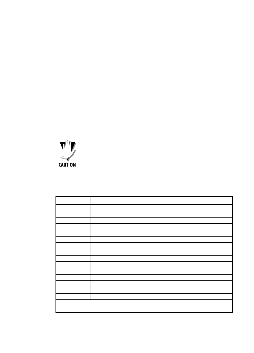
Configuration Methods
The Dual DSU-DP provides methods for both local and
emote configuration. These methods are shown in Table
2-C and are discussed in the following sections.
METHOD STAND ALONE
AT Commands Yes Yes
V.25 Commands Yes Yes
Front Panel Yes Yes
r
DATAM ATE N o Yes
VT 100 No Yes
AT Commands
The Dual DSU-DP can be configured and controlled with
in-band AT commands from an asynchronous DT E port
just as modems are.
Table 2-C
Configuration Methods
Local Remote
To exit the data mode and enter the command mode, the
asynchronous DT E device must transmit a proper escape
sequence or three pluses (+++) to the Dual DSU-DP. A
specified time delay must occur between the last data
character and the first escape sequence character. T his is
the guard time delay, and it can be changed by writing a
value to the S12 register. The default value for the guard
time is one second. For a valid escape sequence to occur,
the DT E must transmit the escape code character three
times in succession with delay between each character
being less than the guard time.
Once the command mode is entered, AT commands can
be transmitted to the Dual DSU-DP to configure most of
the options or initiate tests to check both the Dual DSUDP and the network connections. All command lines
must begin with the AT character set in either capital or
lower case letters.
12 Dual DSU-DP User Manual 61200.128 L1-1
Page 23

The command line may contain a single command or a
series of commands after the AT attention code. When a
series of commands is used, the individual commands
may be separated with spaces for readability. The maximum length for a command line is 40 characters. Each
command line is executed by the Dual DSU-DP upon
receipt of a terminating character. T he default terminating character is a carriage return ( ASCII 013), but it can
be changed by writing a different value to register S3.
Before the terminating character is transmitted, the
command line can be edited by using the backspace
character (ASC I I 008) to erase errors so the proper
commands can be entered. Valid AT commands for the
Dual DSU-DP are listed in the appendix AT Commands.
V.25 bis Commands
When configured for the V.25 bis option, the Dual DSUDP accepts in-band dialing and configuration commands
from both synchronous and asynchronous DT E ports.
Chapter 2. Installation
The V.25 bis option supports the following protocols:
¥ SDLC (Synchronous Data Link Control)
¥ BI-SYN C
¥ ASYNC HRONOUS
SDLC Option
Character Format
¥ Data bits - 8
¥ Parity bit - Ignored
Command Structure
[F][A][C][V.25 bis COMMAND][FCS][F]
The address field [ A] is FFH. The control field [ C ] is set
to 13H except for cases of multi-frame responses. For this
case, the control field is set to 03H in all but the last
frame. T he 03H in the control field indicates that other
frames are to follow while the 13H in the control field
indicates the final frame.
61200.128L1-1 Dual DSU-DP User Manual 13
Page 24

Chapter 2. Installation
Bi-Sync Option
Asynchronous Option
Character Format
¥ Data bits - 7
¥ Parity bit - Odd
Command Structure
[SYN][SYN][STX][V.25 bis COMMAND][ETX]
Character Format
¥ Start bit - 1
¥ Data bits - 7
¥ Parity bit - Even
¥ Stop bit - 1
Command Structure
[V.25 bis COMMAND][CR][LF]
Command Descriptions
The ADTRAN V.25 bis command set is a subset of the
CCITT V.25 bis command set. In addition to the CCITT
commands supported, ADTRAN has added configuration
commands for both local and remote DSUs. The
14 Dual DSU-DP User Manual 61200.128 L1-1
Page 25

Chapter 2. Installation
ADTRAN V.25 bis command set follows:
CI C Connect incoming call
CNL C onfiguration local
CNR C onfiguration remote
CRN C all request with number
CRS C all request using stored number
DI C Disregard incoming call
PRN Program number
RLN Request list of numbers
The following list contains possible responses to V.25 bis
commands:
V A L Valid V.25 command processed
CFIET Call failed on switched network - busy
detected
CFIDE Call failed on switched network - no wink
detected
CFINS C all failed - no dial string in specified
register
INVCU Unknown command detected
INVPS Invalid parameter syntax
INVPV Invalid parameter value
INVBL Invalid local password
INVBM Invalid remote password
INC Incoming call
CNX C all connected
If verbose (wordy) responses are disabled (ATV0), the
following list of three-character responses are the only
ones returned:
V A L Valid V.25 command processed
INV Invalid command received
CFI Call failed
INC Incoming call
CNX C all connected
61200.128L1-1 Dual DSU-DP User Manual 15
Page 26

Chapter 2. Installation
Syntax and Possible Responses
CIC (Connect Incoming Call)
This command causes the DSU to go on-line. For dial
backup units, this command hangs up the dial backup
line and initiates an attempt to reestablish the main ( DDS)
line. There are no parameters associated with this
command. Possible indications include VAL, CNX, and
CFIxx
CNL (Configuration Local)
This command is used to pass AT commands to the local
modem via the V.25 bis command processor. T his allows
the Dual DSU-DP to be configured with AT commands via
a synchronous interface. T he command has the following
format:
CNL[LOCAL PASSWORD;]AT[ONE OR MORE AT
COMMANDS]
A local password may not be required depending on the
present configuration of the unit. Responses to CNL
commands are returned in the data format currently
configured. Possible responses include VAL and I NVn.
CNR (Configuration Remote)
This command is used to pass AT commands over the
network to the remote DSU via the V.25 bis command
processor. T his allows a remote Dual DSU-DP to be
configured from a synchronous interface. The commandÕs
format is as follows:
CNR[REMOTE PASSWORD;]AT[ONE OR MORE AT
COMMANDS]
The remote password may or may not be required depending on the present configuration of the remote unit.
Responses to the CNR commands are returned in the data
format currently configured. Possible responses include
VAL and I NVn.
16 Dual DSU-DP User Manual 61200.128 L1-1
Page 27

Switched 56 Operation
CRN (Call Request with Number)
When the Dual DSU-DP is configured for SW 56 operation, the CRN command causes the DSU to dial the
supplied number. T he commandÕs format follows:
CRN[NUMBER TO BE DIALED]
If no number is included in the command, the number
stored in dial register number 1 is dialed. If no number is
provided and no number is stored in dial register number
1, the Dual DSU-DP responds with the call failure indication C FINS ( C all Failure Indication Not Stored).
For a DBU unit, this command initiates dialing on the
backup circuit. I f the number supplied contains nondialable digits, they are ignored and only the dialable
digits are dialed. Possible responses include VAL, CNX,
and CFIxx.
CRS (Call Request Using Stored Number)
The CRS command causes the Dual DSU-DP to dial the
number stored in the specified register. The format of this
command is as follows:
Chapter 2. Installation
CRS[OPTIONAL SPACE][REGISTER NUMBER 110]
If this command is issued without the register number
parameter, the INVPS ( Invalid Parameter Syntax) response is issued. If this command is issued and the
register parameter is not in the valid range for dialing
registers, the INVPV ( Invalid Parameter Value) response is
returned. Other responses include VAL, CNX, and C FIxx.
61200.128L1-1 Dual DSU-DP User Manual 17
Page 28

Chapter 2. Installation
DIC (Disregard Incoming Call)
This command causes the V.25 bis processor to return to
command mode even if there is an incoming call pending.
This allows local commands to be issued and incoming
calls to be ignored. There are no parameters associated
with this command. The DSU responds with VAL.
PRN (Program Number)
This command stores the supplied number into the
specified register. The command has the following
format:
PRN REGISTER NUMBER;[NUMBER TO BE
STORED]
If this command is entered with no parameters, the INVPS
response is returned. If no register number is included in
the command or if it is invalid, the INVPV response is
returned. This response is also returned if the number to
be stored contains invalid characters. T he characters 1, 2,
3, 4, 5, 6, 7, 8, 9, 0, P, T, and & are valid dial characters.
If no digits are issued with this command, the specified
register is cleared. T he DSU responds with VAL.
RLN (Request List of Numbers)
This command causes the Dual DSU-DP to return the
number stored in the specified register. The format of this
command follows:
RLN [REGISTER NUMBER]
If the register number is invalid, the INV PV response is
returned. When a correct register number is entered, the
following response is returned:
LSN [REGISTER NUMBER];[NUMBER STORED]VAL
If no register number is present in the command, the Dual
DSU-DP responds with a list of all the registers and the
stored numbers. T his list is followed by the VAL
response.
18 Dual DSU-DP User Manual 61200.128 L1-1
Page 29

OVERVIEW
Menu Structure
Chapter 3. Operation
Chapter 3
Operation
The Dual DSU-DP Option Module and Plug-On Board
are both controlled as part of the TSU/HSU using the
methods described in their respective manuals.
Refer to the appropriate TSU/HSU User Manual for
descriptions of front panel indicators and buttons.
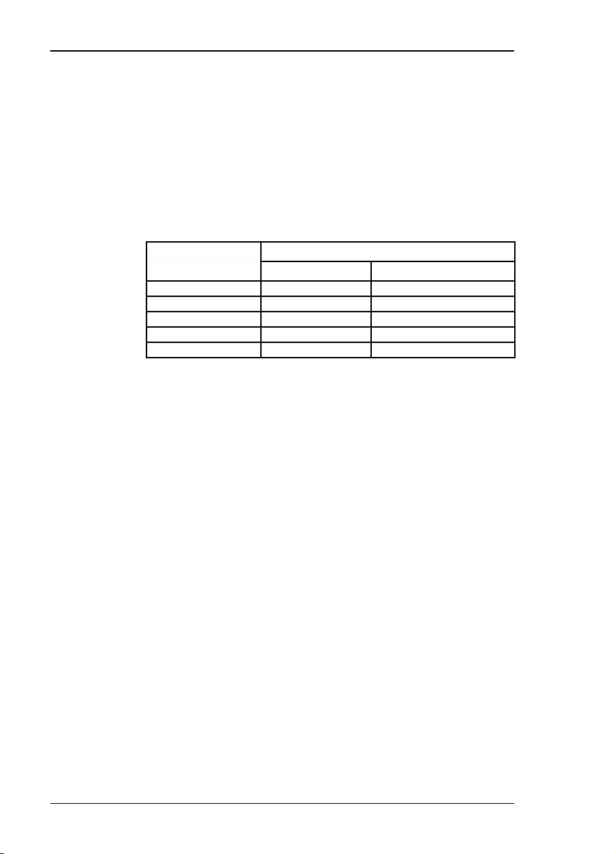
The TSU 100 menu tree is used for illustrative purposes.
When an option module or plug-on board is installed in
the TSU/HSU, the unit adds it to the list of available
options under the various Port menu items. These menu
items are printed in bold italic letters in the limited
overview of the TSU 100 menu shown in Figure 3-1
(complete menu diagram is found in each TSU/HSU
User Manual). The TSU 100 is used as an example of
the TSU/HSU units.
61200.128L1-1 Dual DSU-DP User Manual 19
Page 30
Chapter 3. Operation
TSU 100
MAIN MENU
1)STATUS
2)CONFIG
3)UTIL
4)TEST
1)NETWORK (NI)
2)UNIT
3)MAP XCHNG
4)MAP IN USE A (B)
5)DS0 MAP A
6)DS0 MAP B
7)PORT CONFIG
1)NETWORK TESTS
2)RUN SELF TEST
3)PORT TEST
4)CANCEL TEST
1)NI PERF REPORTS
2)NI ERRORS
3)ACTIVE ALARMS
4)VIEW HISTORY
5)PORT STATUS
1)TIME/DATE
2)FACTORY RESTORE
3)SET PASSCODE
4)UNIT ID
5)SOFTWARE REV
6)PORT UTILITY
Figure 3-1
TSU 100 Main Menu
The Dual DSU-DP menus are all submenus found under
TSU/HSU menu items:
1)STATUS -> 5)PORT STATUS
2)CONFIG -> 7)PORT CONFIG
3)UTIL -> 6)PORT UTIL
4)TEST -> 3)PORT TEST
When accessing PORT, CONFIG, or TEST submenus, the
DSU-DP port must be selected, then remote or local must be
selected.
20 Dual DSU-DP User Manual 61200.128L1-1
Page 31

Menu Operation
Chapter 3. Operation
The Dual DSU-DP menus are accessed from and operate
the same as menus for the TSU 100. Each of the Dual
DSU-DP submenu items are discussed in this manual.
Operation
With the cursor on one of the four Main menu choices:
Press: ENTER or the number key
Results: Display of the first two submenu items with
the cursor on the first item
Use: The down scroll key to place the cursor on
the desired item
Press: ENTER
Results: Display of the first two submenu choices
61200.128L1-1 Dual DSU-DP User Manual 21
Page 32

Chapter 3. Operation
22 Dual DSU-DP User Manual 61200.128L1-1
Page 33

CONFIGURATION OVERVIEW
Local and Remote Configuration
The DSU-DP option module and/or plug-on board
(DSU-DP) can be configured locally using the front
panel or remotely by establishing communications with
another ADTRAN DSU product. The front panel of the
local TSU/HSU can also be used to configure the
remote DSU. During remote configuration, the DSU-DP
prompts for the remote address before continuing to the
Configuration (CONFIG) menus.
Chapter 4. Configuration
Chapter 4
Configuration
Configuration Menu
The Configuration menu consists of five sub-menus
relating to a specific interface or function of the DSU-DP
that requires setup. These functions and their corresponding functions are:
1) Network Options: Network Interface Parameters
2) DTE Options: DTE Interface Parameters
3) Test Options: Test Parameters
4) Dial Options: Dialing Parameters
5) Manual Commands: Specialty commands reserved
for experienced DSU operators
61200.128L1-1 Dual DSU-DP User Manual 23
Page 34

Chapter 4. Configuration
The DSU-DP contains two different user profiles (sets of
configurations options) that are stored in read only
memory (see the appendix, Default Configuration
Profiles). The unit is shipped from the factory with
profile number 1 (default configuration) loaded into the
current (nonvolatile configuration) memory. If profile 1
matches requirements for the system, no additional
configuration is required to put the unit into service. If
profile 1 does not match system requirements, it can be
modified, or the other profile that more closely matches
the system requirements can be loaded into current
memory. When a different profile is loaded, or the
existing profile is modified, it is stored in the current
(nonvolatile configuration) memory. The DSU-DP is
then configured with that profile every time power is
turned on or until the unit is reset.
A complete Dual DSU-DP Configuration menu tree is
found in the appendix Dual DSU-DP Configuration Menu
Tree.
24 Dual DSU-DP User Manual 61200.128L1-1
Page 35

CONFIGURING NETWORK OPTIONS
:
Network Options
The NETWORK OPTIONS configuration parameters
control the network operation of the DSU-DP.
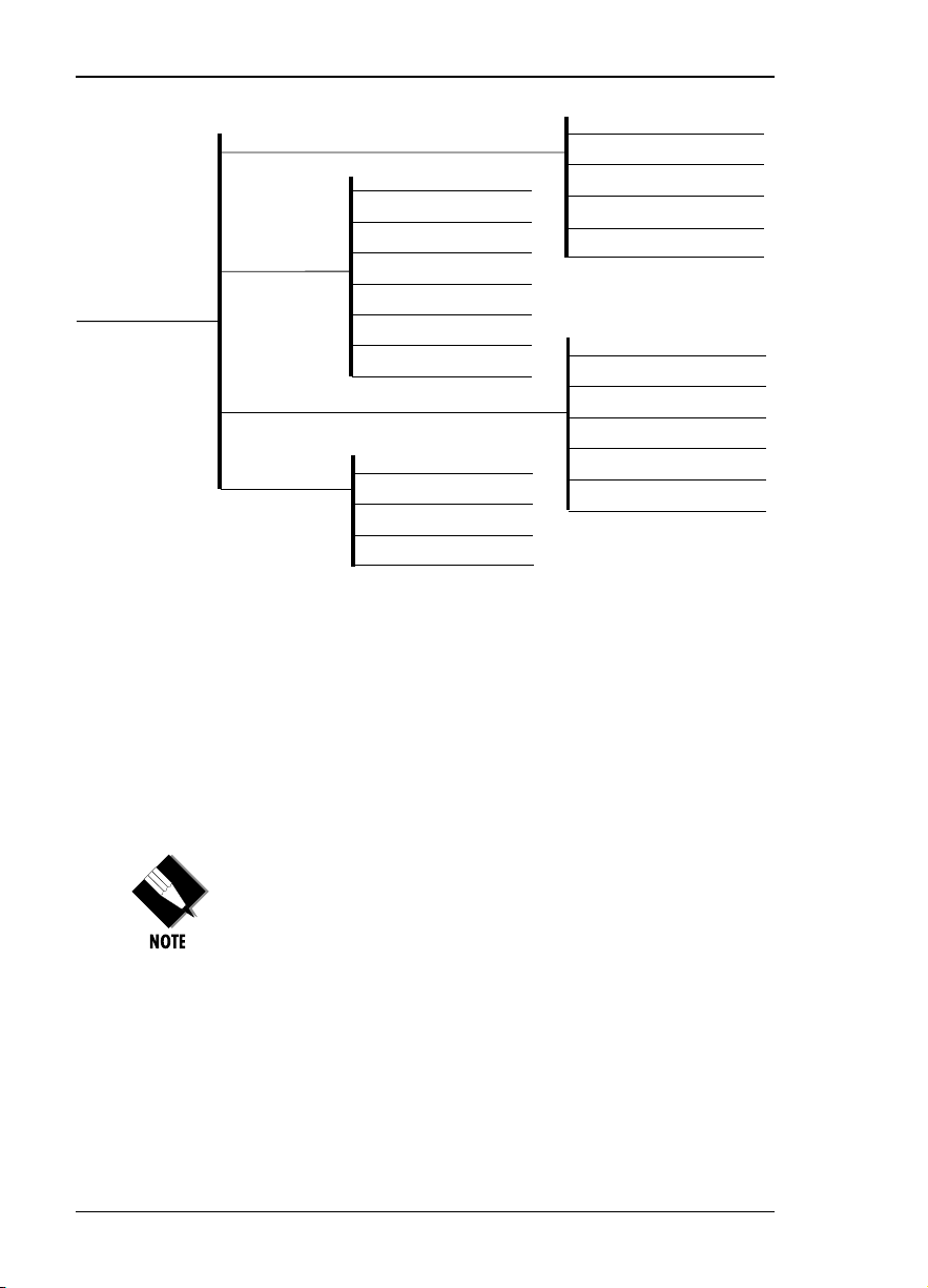
Network Rate
The Network Rate option sets the network operating
speed. The unit should be set to the rate required by the
DDS Service. The DSU DP also supports subrate DTE
data over a 56 kbps or 64 kbps loop. The network rate
must be set independently of the DTE rate.
Seven network rate selections are available (see Figure
4-1).
1)NETWORK OPTS
1)LOCAL
5)PORT CONFIG
PORT: 0.1 NX56/64
PORT: 1.2 DSU-DP 4)DIAL OPTIONS
PORT: 1.1 DSU-DP 5)MANUAL COMMAND
2)REMOTE ENTER ADDRESS
2)DTE OPTIONS
3)TEST OPTIONS
Chapter 4. Configuration
2.4K
4.8K
1)NETWORK RATE
2)NETWORK ADDR:
3)REMOTE CONFIG:
4)NETWORK TYPE:
9.6K
19.2K
38.4K
56K
64K
Figure 4-1
Setting Network Rate Options
61200.128L1-1 Dual DSU-DP User Manual 25
Page 36

Chapter 4. Configuration
Network commands are provided in Table 4-A.
Table 4-A
Loop Rate Commands
Front Panel AT Command
2.4K % B 1
4.8K % B 2
9.6K % B 3
19.2K % B 4
38.4K % B 5
56K % B 6
64K clear channel % B 7
26 Dual DSU-DP User Manual 61200.128L1-1
Page 37

Network Address
X
A two-digit decimal address can be assigned to each
DSU-DP. This addressing capability makes it possible to
perform remote configuration and testing in point-topoint and multi-drop networks. Figure 4-2 shows the
menu path used to change the network address. The
factory default setting is 0.
Chapter 4. Configuration
1)NETWORK RATE:
1)NETWORK OPT.
1)LOCAL 3)REMOTE CONFIG:
5)PORT CONFIG 4)NETWORK TYPE:
PORT: 0.1 NX56/64
PORT: 1.2 DSP-DP 3)TEST OPTIONS
PORT: 1.1 DSP-DP 4)DIAL OPTONS
2)REMOTE 2)DTE OPTIONS
5)MANUAL COMMAND
2)NETWORK ADDR: X
Figure 4-2
Setting the Network Address
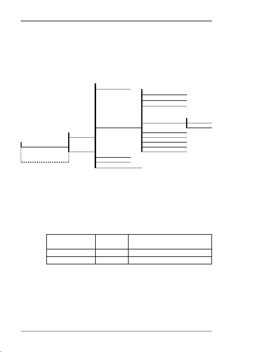
Table 4-B shows the AT command used to set the
network address Table 4-B
Table 4-B
Network Address Command
Front
Panel
XX (Decimal) _N=xx Assigns a 2 digit Network Address
AT
Command
Description
61200.128L1-1 Dual DSU-DP User Manual 27
Page 38

Chapter 4. Configuration
Remote Configuration Option
This option sets up the DSU-DP to accept or reject
remote configuration commands. Figure 4-3 shows the
menu path for enabling/disabling remote configuration. The factory default setting is ENABLED.
1)NETWORK OPT.
5)PORT CONFIG
PORT: 0.1 NX56/64 2)DTE OPTIONS
1.2 NX56/64
1.1 NX56/64 4)DIAL OPTIONS
1)LOCAL
2)REMOTE
3)TEST OPTIONS
5)MANUAL COMMAND
Table 4-C shows the equivalent AT commands used to
enable or disable remote configuration.
1)NETWORK RATE:
2)NETWORK ADDR:
DISABLED
3)REMOTE CONFIG: ENABLED
4)NETWORK TYPE:
Figure 4-3
Enabling/Disabling Remote Configuration
Table 4-C
Remote Configuration Commands
Front
Panel
AT
Command
Description
DISABLE &P4 Disable Remote Configuration
ENABLE &P5 Enable Remote Configuration
28 Dual DSU-DP User Manual 61200.128L1-1
Page 39

Network Type
Chapter 4. Configuration
This option configures the DSU-DP for the specific type
of network being used. The factory default setting is
DEDICATED (see Figure 4-4).
1)NETWORK RATE:
1)NETWORK OPT.
2)NETWORK ADDR:
3)REMOTE CONFIG:
5)PORT CONFIG
PORT: 0.1 NX56/64
PORT: 1.2 DBU-DP 3)TEST OPTIONS
PORT: 1.1 DBU-DP 4)DIAL OPTIONS
1)LOCAL
2)REMOTE
2)DTE OPTIONS
5)MANUAL COMMAND
4)NETWORK TYPE: DEDICATED
Setting Network Type Options
Table 4-D shows the equivalent AT commands that
perform the same configuration functions.
Network Type Commands
Front
Panel
AT
Command
Description
DEDICATED &L0 Any 4-wire DDS Network
AT&T/MCI SW 56 &L1 AT&T/MCI Switched 56 Service
US SPRINT SW 56 &L2 US SPRINT Switched 56 Service
AT&T/MCI SW56
US SPRINT SW56
Figure 4-4
Table 4-D
61200.128L1-1 Dual DSU-DP User Manual 29
Page 40

Chapter 4. Configuration
CONFIGURING DTE OPTIONS
The DTE OPTIONS menu is used to select the configuration parameters that control the operation of the DSUDP DTE Interface such as the DTE rate, data format,
DTE command options, transmit clock, CS options, antistream, and CD options.
DTE Rate
The selectable DTE rates over a 56 or 64 kbps network
are shown in Figure 4-5. If a slower network rate is
selected, the DTE rate automatically matches the
network rate. If an attempt is made to set the DTE rate
for network rates slower than 56 kbps, the DSU-DP will
automatically change the option setting to SAME AS
NET. The factory default setting is 56K.
If asynchronous mode is set, the 56K option is actually 57.6
kbps.
2.4K
1)NETWORK OPTS 9.6K
1)DTE RATE: 38.4K
1=LOCAL 3)DTE CMD OPTION:
5)PORT CONFIG 5)CS OPTIONS:
PORT: 0.1 NX56/64 2=REMOTE 6)ANTI-STREAM:
PORT: 1.2 DSU-DP 7)CD OPTIONS:
PORT: 1.1 DSU-DP 8)TR OPTIONS:
2)DTE OPTIONS 4)TRANSMIT CLOCK:
3)TEST OPTIONS
4)DIAL OPTIONS
5)MANUAL OPTIONS
2)DATA FORMAT: SAME AS NET
9)SR OPTIONS:
4.8K
19.2K
56K
64K
64K SCRAMBLED
Figure 4-5
DTE Rates for 56 or 64 kbps Network Rate
The equivalent AT commands for setting the DTE rate
for a 56 kbps or 64 kbps are shown in Table 4-E.
30 Dual DSU-DP User Manual 61200.128L1-1
Page 41

Chapter 4. Configuration
Table 4-E
DTE Rate AT Commands
Front
Panel
AT
Command
Description
DTE 2.4K %K3 DTE rate 2.4K sync and async
DTE 4.8K %K4 DTE rate 4.8K sync and async
DTE 9.6K %K5 DTE rate 9.6K sync and async
DTE 19.2K %K6 DTE rate 19.2K sync and async
DTE 38.4K %K7 DTE rate 38.4K sync and async
DTE 56K %K8 DTE rate 56K sync or 57.6 async
64K %K9 - F0 DTE rate 64K
64K SCRAMBLER %K9 - F1 DTE rate 64K with data scrambler enabled
For 64 kbps clear channel operation, there is a possibility
that the DTE data sequences might mimic network loop
maintenance functions and erroneously cause other network
elements to activate loopbacks. To prevent this, the 64K
SCRAMBLER option should be selected for both the local
and remote DSU.
61200.128L1-1 Dual DSU-DP User Manual 31
Page 42

Chapter 4. Configuration
Data Format
The DATA FORMAT option is used to select either the
synchronous or asynchronous mode of operation for
the DTE interface. The factory default setting is SYNCHRONOUS (see Figure 4-6). If asynchronous is
chosen, the length of the data bytes must be selected.
1)NETWORK OPTS 1)DTE RATE:
2)DATA FORMAT: SYNCHRONOUS
2)DTE OPTIONS ASYNC 10 BITS
1)LOCAL 4)TX CLOCK:
5) PORT CONFIG 6)ANTI-STREAM:
PORT: 0.1 NX56/64 2)REMOTE 7)CD OPTIONS:
PORT: 1.2 DSU-DP 8)TR OPTIONS:
PORT: 1.1 DSU-DP 9)SR OPTIONS:
3)TEST OPTIONS
4)DIAL OPTIONS
5)MANUAL COMMAND
Selecting Asynchronous or Synchronous Data Format
3)DTE CMD OPTION: ASYNC 11 BITS
5)CS OPTIONS:
ASYNC 9 BITS
Figure 4-6
Table 4-F shows the AT commands that can be used to
set the DATA FORMAT.
Table 4-F
Data Format Commands
Front
Panel
For asynchronous options, select the length of the data bytes.
SYNCHRONOUS &Q2 Always synchronous
ASYNC 9 BITS &Q0 ASYNCH with 9 bits including start, stop, parity
ASYNC 10 BITS &Q0 ASNYCH with 10 bits including start, stop, parity
ASYNC 11 BITS &Q0 ASYNCH with 11 bits including start, stop, parity
AT
Command
Description
For AT command set, the async word length must be set via
the front panel.
32 Dual DSU-DP User Manual 61200.128L1-1
Page 43

DTE Command Option
The DTE COMMAND option is used to enable AT
commands from the DTE, enable V.25 bis SDLC (synchronous data link control) commands, enable V.25
(bisync and async), or disable all DTE command modes
(see Figure 4-7).
Chapter 4. Configuration
1)NETWORK OPTS
2)DTE OPTIONS V.25 SYNC
1=LOCAL 4)TX CLOCK:
5)PORT CONFIG 6)ANTI-STREAM:
PORT: 0.1 NX56/64 2=REMOTE 7)CD OPTIONS:
PORT: 1.2 DSU-DP 8)TR OPTIONS:
PORT: 1.1 DSU-DP 9)SR OPTIONS:
3)TEST OPTIONS
4)DIAL OPTIONS
5)MANUAL COMMAND
1)DTE RATE:
2)DATA FORMAT:
3)DTE CMD OPTION: DISABLED
5)CS OPTIONS:
Selecting the DTE Command Option
When the unit is in DTE CMD OPTION mode (idle in
SW56 mode, forced with TR option, or from escape sequence
in AT mode) with AT COMMAND SET or V.25 SYNC
selected, the DTE format is independent of the DATA
FORMAT option. However, if V.25 BSC/ASYNC is selected,
the unit will use V.25 BISYNC (BSC) commands for
synchronous data format or V.25 ASYNC commands for
asynchronous data format.
AT COMMAND SET
V.25 BSC/ASYNC
Figure 4-7
61200.128L1-1 Dual DSU-DP User Manual 33
Page 44
Chapter 4. Configuration
4
Transmit Clock
The TRANSMIT CLOCK option is used to select the
source of the clock used to transfer data from the DTE
into the DSU-DP. Figure 4-8 shows the menu path used
to set the TRANSMIT CLOCK option.
1)NETWORK OPTS
2)DTE OPTIONS EXTERNAL
1)LOCAL 6)ANTI-STREAM:
5)PORT CONFIG 8)TR OPTIONS:
PORT: 0.1 NX56A/6
PORT: 1.2 DSU-DP 3)TEST OPTIONS
PORT: 1.1 DSU-DP 4)DIAL OPTIONS
2)REMOTE 9)SR OPTIONS:
5)MANUAL COMMAND
1)DTE RATE:
2)DATA FORMAT:
3)DTE CMD OPTION:
4)TX CLOCK: NORMAL
5)CS OPTIONS:
7)CD OPTIONS:
Transmit Clock Options
Table 4-G shows the AT commands used to set the
Transmit Clock option.
Transmit Clock AT Commands
Front
Panel
AT
Command
Description
NORMAL &X0 TX clock from DSU selected
EXTERNAL &X1 ETC clock from DTE selected
Figure 4-8
Table 4-G
The EXTERNAL clock option is normally used in
modem tail circuit applications. A DSU-to-modem
interconnect diagram for this application is shown in the
appendix, DSU-to-Modem Interconnect.
34 Dual DSU-DP User Manual 61200.128L1-1
Page 45

Chapter 4. Configuration
The EXTERNAL clock option is also recommended
when the EIA-232 connector is used for 56 kbps and 64
kbps applications. A special DSU cable diagram for this
application is shown in the appendix, EIA-232 Connector.
Using this option and a special cable eliminates data
errors caused by excessive delays in the DTE transmit
clock receiver and transmit data driver.
61200.128L1-1 Dual DSU-DP User Manual 35
Page 46

Chapter 4. Configuration
CS Options
The CS (clear to send) OPTIONS menu is used to select
one of seven different control modes for the CS lead.
Figure 4-9 shows the menu path used to access the CS
OPTIONS menu. The default factory setting is
FOLLOWS RS with CS DELAY SHORT.
1)NETWORK OPTS 1)DTE RATE:
2)DTE OPTIONS 3)DTE CMD OPTION:
1)LOCAL 5)CS OPTIONS: FORCED ON
5)PORT CONFIG 7)CD OPTIONS: FOLLOW RS LONG
PORT: 0.1 NX56/64 2)REMOTE 8)TR OPTIONS: FOLLOW CD
PORT: 1.2 DSU-DP 9)SR OPTIONS: FOLLOW RS+CD S
PORT: 1.1 DSU-DP 3)TEST OPTIONS FOLLOW RS+CD L
4)DIAL OPTIONS OFF WITH LOC D
5)MANUAL COMMAND
2)DATA FORMAT:
4)TRANSMIT CLOCK:
6)ANTI-STREAM: FOLLOW RS SHRT
Figure 4-9
Selecting CS Options
If one of the options chosen involves request to send
(RS), then the delay from RS to CS must be selected.
Table 4-H shows the AT Commands used to set the CS
OPTIONS.
36 Dual DSU-DP User Manual 61200.128L1-1
Page 47

Chapter 4. Configuration
p
p
Table 4-H
CS Options AT Commands
Front
Panel
AT
Command
Description
FORCED ON &R0 CS always on.
FOLLOWS RS SHRT &R1/_D0
CS on with RS after delay; off when
RS or if DSU cannot pass data.
FOLLOW RS LONG &R1/_D1
Same as FOLLOW RS SHRT
FOLLOW CD &R2 CS off when CD goes off or if DSU
cannot
ass data.
FOLLOWS RS+CD S &R3/_D0 CS follows RS after delay and also
off if CD off. If CD goes off after
RS is on, DSU _DP will turn off CS
but continue to pass data until RS
goes off. CS also off if DSU cannot
ass data.
FOLLOW RS+CD L &R4/_D1
Same as FOLLOW RS+CD S
OFF WITH LOCD &R4 Off 5 sec after LOCD (loss of
carrier detect). Valid only in SW56
mode. CS is forced on but will turn
off for 5 seconds after a call is
disconnected.
61200.128L1-1 Dual DSU-DP User Manual 37
Page 48

Chapter 4. Configuration
Specified times for the short and long delays at the
different operating speeds are shown in Table 4-I.
Table 4-I
Short and Long Delays
at Different Operating Speeds
Rate
64K 1.1ms 16.1ms
56K 1.1ms 16.1ms
38.4K 1.5ms 16.5ms
19.2K 1.5ms 16.5ms
9.6K 1.5ms 16.5ms
4.8K 1.9ms 16.9ms
2.4K 3.8ms 18.8ms
Short
Option
Long
Option
Tolerance
±.4ms
±.4ms
±.4ms
±.4ms
±.4ms
±.7ms
±1.3ms
38 Dual DSU-DP User Manual 61200.128L1-1
Page 49

Anti-Stream
Chapter 4. Configuration
The ANTI-STREAM option is used to select the antistream timeout. Figure 4-10 shows the menu path used
to access the ANTI-STREAM options menu. The antistream timeout is the maximum time the DSU-DP
transmits data into the network from the DTE. This
feature prevents one DTE device on a multi-drop network
from continuously tying up the transmit circuit back to
the master DSU.
The anti-stream timer is reset to zero when RS changes
to the active state and is updated every second while RS
is active. When the anti-stream timeout expires, the
DSU-DP stops transmitting DTE data into the network
but continues to accept data from it. This condition
exists until the DTE deactivates the RS input.
1)NETWORK OPTS 1)DTE RATE:
2)DTE OPTIONS 5)CS OPTIONS: TIMER OFF
1)LOCAL 7)CD OPTIONS: TIME 30 SEC
5)PORT CONFIG 9)SR OPTIONS:
PORT: 0.1 NX56/64 2)REMOTE
PORT: 1.2 DSU-DP 3)TEST OPTIONS
PORT: 1.1 DSU-DP 4)DIAL OPTIONS
5)MANUAL COMMAND
2)DATA FORMAT:
3)DTE CMD OPTION:
4)TX CLOCK:
6)ANTI-STREAM TIME 10 SEC
8)TR OPTIONS: TIME 60 SEC
Figure 4-10
Anti-Stream Options
61200.128L1-1 Dual DSU-DP User Manual 39
Page 50

Chapter 4. Configuration
The factory default setting is TIMER OFF. Table 4-J
shows the available options and their AT commands.
Table 4-J
Anti-Stream AT Commands
Front
Panel
TIMER OFF %T0 Anti-stream timer disabled
TIME 10 SEC. %T1 Timeout equal 10 seconds
TIME 30 SEC. %T2 Timeout equal 30 seconds
TIME 60 SEC. %T3 Timeout equal 60 seconds
AT
Command
Description
40 Dual DSU-DP User Manual 61200.128L1-1
Page 51

CD Options
Chapter 4. Configuration
The CD OPTIONS menu is used to select one of three
different control modes for the receive line signal
detector (CD) lead. The default factory setting is
NORMAL (see Figure 4-11).
1)NETWORK OPTS 1)DTE RATE:
2)DTE OPTIONS 5)CS OPTIONS
1=LOCAL 7)CD OPTIONS: FORCED ON
5)PORT CONFIG 9)SR OPTIONS: OFF WITH LOCD
PORT: 0.1 NX56/64 2=REMOTE
PORT: 1.2 DSU-DP 3)TEST OPTIONS
PORT: 1.1 DSU-DP 4)DIAL OPTIONS
5)MANUAL COMMAND
2)DATA FORMAT:
3)DTE CMD OPTION:
4)TX CLOCK:
6)ANTI-STREAM:
8)TR OPTIONS: NORMAL
Figure 4-11
Selecting CD Options
Table 4-K shows the equivalent AT commands for setting
CD options.
Table 4-K
CD Options AT Commands
Front
Panel
AT
Command
Description
FORCED ON &C0 On all the time.
NORMAL &C1
On only when data present on
network.
OFF WITH LOCD &C2 On except after disconnect in
Switched 56 application.
61200.128L1-1 Dual DSU-DP User Manual 41
Page 52

Chapter 4. Configuration
g
y
y
TR Options
The TR OPTIONS menu is used to select the DSU-DP
response to the data terminal ready (TR) lead. The
factory default setting is IGNORED (see Figure 4-12).
1)NETWORK OPT.
1)DTE RATE:
2)DATA FORMAT:
2)DTE OPTIONS 4)TX CLOCK:
1)LOCAL 6)ANTI-STREAM:
5)PORT CONFIG 8)TR OPTIONS: I GNORED
PORT: 0.1 NX56/64 2)REMOTE 9)SR OPTIONS: IDLE WHEN OFF
PORT: 1.1 DSU-DP OFF->ON DIAL #1
PORT: 1.2 DSU-DP 3)TEST OPTIONS OFF->ON DIAL #2
4)DIAL OPTIONS
5)MANUAL COMMAND
Table 4-L shows the equivalent AT commands for setting
TR OPTIONS.
3)DTE CMD OPTION:
5)CS OPTIONS:
7)CD OPTIONS:
Figure 4-12
Selecting TR Options
Table 4-L
TR Options AT Commands
Front
Panel
AT
Command
Description
IGNORE &D0 Ignore the TR input.
IDLE WHEN OFF &D2 See the followin
Note.
OFF>ON DIAL #1 &D3 Dial Stored #1: TR goes off to on
(SW56 onl
).
OFF>ON DIAL #2 &D4 Dial Stored #2: TR goes off to on
(SW56 onl
).
For IDLE WHEN OFF option: In SW56 mode, TR Off
causes the DSU to go On Hook (Idle). The unit also will not
dial out if TR is off. In dedicated mode, the DSU goes into
DTE command mode when TR goes off. When TR goes on,
if the DSU does not receive a command in the number of
seconds set in S40, the DSU goes into data mode.
42 Dual DSU-DP User Manual 61200.128L1-1
Page 53

Chapter 4. Configuration
SR Options
The SR OPTIONS menu is used to select the operating
mode for the data set ready (SR) lead. The factory
default setting is OFF W/TEST + OOS (shown in Figure
4-13).
1)NETWORK OPTS
1)DTE RATE)
2)DATA FORMAT:
2)DTE OPTIONS 4)TX CLOCK:
1)LOCAL 6)ANTI-STREAM:
5)PORTCONFIG 8)TR OPTIONS: FORCED ON
PORT: 0.1 NX56/64 2)REMOTE 9)SR OPTIONS: OFF W/OOS ONLY
PORT: 1.2 DSU-DP OFF W/LOCD
PORT: 1.1 DSU-DP 3)TEST OPTIONS OFF W/TEST
4)DIAL OPTIONS OFF W/TEST+OOS
5)MANUAL OFF W/TST+LOCD
3)DTE CMD OPTION:
5)CS OPTIONS:
7)CD OPTIONS:
Figure 4-13
Setting SR Options
Table 4-M shows the AT commands for setting SR
OPTIONS.
Table 4-M
SR Options AT Commands
Front
Panel
AT
Command
Description
FORCED ON &S0 Always on.
Off when network Out Of
OFF W/OOS ONLY &S1
Service (OOS).
Off 5 seconds after disconnect
OFF W/LOCD &S3
(SW56 only).
OFF W/TEST &S0_C0 Off when unit is in test.
OFF W/TEST +00S &S1_C0 Off in test or OOS.
Off 5 seconds after disconnect
OFF W/TST +LOCD &S5
61200.128L1-1 Dual DSU-DP User Manual 43
or test.
Page 54

Chapter 4. Configuration
TEST OPTIONS
The TEST OPTIONS menu enables or disables different
test modes and specifies the maximum test time
allowed.
Test Timeout
The TEST TIMEOUT option sets the length of time a
DSU-DP remains in a test mode before automatically
returning to the data mode. Enter the timeout from 0 to
255 seconds. The factory default setting is off (0).
Figure 4-14 shows the menu path used to access TEST
TIMEOUT.
1)NETWORK OPTS
2)DTE OPTIONS
1)LOCAL 1)TEST TIME: XX
3)TEST OPTIONS 2)RDL TEST:
5)PORT CONFIG
PORT: 0.1 NX56/64 2)REMOTE
PORT: 1.2 DSU-DP 4)DIAL OPTIONS
PORT: 1.1 DSU-DP 5)MANUAL COMMAND
Figure 4-14
Setting Test Timeout Option
Table 4-N shows the equivalent AT command for setting
the TEST TIMEOUT.
Table 4-N
Test Timeout AT Command
Front
Panel
AT
Command
Description
ENTER TIMEOUT S18=x Specify 0 - 255 seconds test timeout
44 Dual DSU-DP User Manual 61200.128L1-1
Page 55

Remote Digital Loopback
The RDL (Remote Digital Loopback) option specifies
whether or not the DSU-DP responds to an RDL request
from the far end of the circuit. The factory default
setting is RDL ENABLED. Figure 4-15 shows the menu
path used to access this option.
1)NETWORK OPTS
2)DTE OPTIONS
Chapter 4. Configuration
1)LOCAL
5)PORT CONFIG
PORT: 0.1 NX56/64 2)REMOTE 4)DIAL OPTIONS
PORT: 1.2 DSU-DP 5)MANUAL COMMAND
PORT: 1.1 DSU-DP
3)TEST OPTIONS 2=RDL TEST: DISABLED
Table 4-O shows the equivalent AT commands for setting
the RDL option.
Remote Digital Loopback AT Commands
Front
Panel
AT
Command
RDL DISABLED &T5 RDL request from remote DSU ignored
RDL ENABLED &T4 RDL request accepted
1=TEST TIME: ENABLED
Figure 4-15
Remote Digital Loopback
Table 4-O
Description
61200.128L1-1 Dual DSU-DP User Manual 45
Page 56

Chapter 4. Configuration
CONFIGURING DIAL OPTIONS
The DIAL OPTIONS menu stores up to two phone
numbers and defines the AUTO ANSWER operation of
the DSU-DP when it is configured for Switched 56
operation.
Phone Number
The DSU-DP stores up to two numbers of 36 digits each.
Edit a phone number by reentering the entire number.
This process overwrites the previously stored number.
Figure 4-16 shows the menu path used to access the
PHONE NUMBERS option.
1)NETWORK RATE
1)LOCAL 3)TEST OPTIONS
5)PORT CONFIG 1)PHONE NUMBERS EDIT: (1-2) NNNNNNN
PORT: 0.1 NX56/64 2)RE MO TE 4)DIAL OPTIONS
PORT: 1.2 NX56/64 2)AUTO ANSWER:
PORT: 1.2 DSU-DP 5)MANUAL
2)DTE OPTIONS
STORED NUMBER TO
Figure 4-16
Editing Stored Phone Numbers
Table 4-P shows the AT Command for storing phone
numbers.
Table 4-P
AT Command for Storing Phone Numbers
AT
Command
Description
&Zn= Store Phone Number
46 Dual DSU-DP User Manual 61200.128L1-1
Page 57

Chapter 4. Configuration
E
Auto Answer
The AUTO ANSWER option is used to specify how
incoming calls are to be answered. If ENABLED,
incoming calls are automatically answered by the DSUDP. If DISABLED, an incoming call can be answered
manually by an AT or V.25 command from the DTE, or
by raising TR from the DTE. Figure 4-17 shows the
menu path used to enable or disable this option. The
default setting is AUTO ANSWER ENABLED.
1)NETWORK TYPE
1)LOCAL 3)TEST OPTIONS
5)PORT CONFIG 1)PHONE NUMBER
PORT: 0.1 NX56/64 2)REMOT
PORT: 1.2 DSU-DP 2)AUTO ANSWER DISABLED
PORT: 1.1 DSU-DP 5)MANUAL COMMAND ENABLED
2)DTE OPTIONS
4)DIAL OPTIONS
Figure 4-17
Enabling/Disabling the Auto Answer Function
Table 4-Q show the AT Commands available for the
AUTO ANSWER option.
Table 4-Q
AT Commands for Auto Answer
Front
Panel
AT
Command
Description
DISABLED _J0 Auto Answer disabled
ENABLED _J1 Auto Answer enabled
61200.128L1-1 Dual DSU-DP User Manual 47
Page 58

Chapter 4. Configuration
MANUAL COMMAND
The MANUAL COMMAND option is a shortcut method
for entering configuration and control commands for the
DSU-DP.
The first display prompts the user to enter the command
number.
Figure 4-18 shows the menu path for MANUAL COMMAND. The available manual commands are listed in
Table 4-R.
COMMAND:00
1)LOCAL 2)DTE OPTIONS
5) PORT CONFIG 4)DIAL OPTIONS
PORT: 0.1 NX56/64 2)REMOTE COMMAND:XX
PORT: 1.2 DSU-DP 5)MANUAL COMMAND COMMAND:XX VALUE:YY
PORT: 1.1 DSU-DP
1)NETWORK OPTS
3)TEST OPTIONS
Figure 4-18
Manual Command
Use the number keys to enter the hexadecimal command number. Press Enter to complete. Once the
command number is entered, the display shows both the
command number and the present value or setting for
the command. The command value can be edited or
reissued with the existing value.
COMMAND: XX
VALUE: YY
Use the number keys to enter the hexadecimal value.
Press Enter to complete. The system briefly displays
COMMAND ACCEPTED and returns to the active
menu.
48 Dual DSU-DP User Manual 61200.128L1-1
Page 59

Chapter 4. Configuration
Table 4-R
Manual Commands
Command Description Command Value
AT Command Echo
Disable 82 00
Enable 82 01
AT Result code
Enable 85 00
Disable 85 01
AT Long or Short code
Short form 86 00 to FF
Long form 86 00 to FF
AT Escape Character 2 00 to FF
AT CR Character 3 00 to FF
AT LF Character 4 00 to FF
AT BS Character 5 00 to FF
AT Escape Char. Timer 0C 00 to FF
Abort Call Timer 7 00 to FF
DTR Recognize Delay (x 2.5ms) 19 00 to FF
DTR Initiated Command Timeout (seconds) 28 00 to FF
Load Factory Opt.
Option Set #1 8A 00
Option Set #2 8A 01
Store User Profile
Save to Profile 0 91 00
Save to Profile 1 91 01
Select User Profile
Power Up Profile 0 93 00
Power Up Profile 1 93 01
Network Address Lock
Network Addr. Unlock C3 00
Network Addr. Lock C3 01
EIA LLB SIGNAL
Disable 9C 00
Enable 9C 01
61200.128L1-1 Dual DSU-DP User Manual 49
Page 60

Chapter 4. Configuration
50 Dual DSU-DP User Manual 61200.128L1-1
Page 61

DIALING OVERVIEW
In Switched 56 mode (SW56) the DSU-DP operates as a
4-wire Switched 56 DSU. Call initiation and termination
can be accomplished through either the TSU/HSU front
panel or the DTE interface via the AT command set or
V.25 bis. The AT command set and V.25 bis are covered
in other chapters. This chapter covers dialing via the
front panel.
Chapter 5. Dialing
Chapter 5
Dialing
Figure 5.1 describes the menu path used to initiate a
call.
1)TIME/DATE
2)FACT RESTORE
3)SET PASSCODE
3)UTIL 4)UNIT I.D.
5)SOFTWARE REV 1=DIAL STORED #
6)PORT UTILITY 1)CALL/HANG-UP 2=ENTER DIAL #
1.X DSU-DP 2)DSU-DP REV? 3=REDIAL LAST #
Figure 5-1
Menu Path to Initiate a Call
If the DSU-DP is not configured for either AT&T/MCI
SW56 or Sprint SW56, the unit displays:
NOT IN SW56 MODE PRESS <CANCEL>
61200.128L1-1 Dual DSU-DP User Manual 51
Page 62

Chapter 5. Dialing
Once you enter the CALL/HANG-UP menu, one of three
menus appears based on the status of the SW56 network. These three menus are discussed in this chapter.
1. No Call Active
If no call is active the DSU-DP is idle and the screen
displays the menu shown in Figure 5.1.
• To dial a stored telephone number, press 1 (for DIAL
STORED #) followed by Enter. The unit displays the
two stored telephone numbers. Enter 1 or 2 for the
desired stored number and press Enter to initiate
dialing.
• To dial a telephone number not already stored, press 2
(for ENTER DIAL #) followed by Enter. The screen
goes blank and the cursor is flashing in the upper left
hand corner. Begin entering your telephone number
and press Enter to intiate dialing.
• To dial the previous number that was called, press 3
(for REDIAL LAST #) followed by Enter. The DSU
initiates dialing the last telephone number dialed.
Once dialing has been initiated, the DSU-DP turns on
the status messages. The first status message is DIALING followed by each digit of the telephone number to
dial as it is being dialed out. If the network fails to send
a wink (SW56 equivalent of a dial tone), the status
message displayed is NO WINK FROM CO for approximately five (5) seconds followed by IDLE.
If the SW56 network is working properly, the DIALING
message persists until the distant DSU answers the call,
upon which the status message changes to DATA MODE.
Press the CANCEL button to exit from the status
messages at any time.
52 Dual DSU-DP User Manual 61200.128L1-1
Page 63

Chapter 5. Dialing
2. Call Is Active
If a call is active (DSU-DP status = DATA MODE) upon
entering the CALL/HANG-UP menu, the following is
displayed:
1 = HANG UP (Flashing)
2 = STAY ON LINE
Press 1 (for HANG-UP) followed by Enter to disconnect
the call. The display backs out to PORT UTILITY. To
see status messages, press 2 (for STAY ON-LINE) and
the status messages are displayed. Press Cancel to stop
viewing status messages.
3. Receiving an Incoming Call with Auto Answer
Disabled
If the DSU is receiving an incoming call and Auto
Answer is disabled, upon entering the CALL/HANG-UP
menu the following is displayed:
1 = ANSWER CALL (Flashing)
2 = STAY IDLE
Press Enter to answer the call, otherwise press Cancel.
If answering is selected, the DSU momentarily displays
COMMAND ACCEPTED and then returns the display to
PORT UTILITY.
61200.128L1-1 Dual DSU-DP User Manual 53
Page 64

Chapter 5. Dialing
54 Dual DSU-DP User Manual 61200.128L1-1
Page 65

TEST OVERVIEW
Chapter 6. Testing & Troubleshooting
Chapter 6
Testing & Troubleshooting
The DSU-DP performs a variety of diagnostic functions
that isolate portions of the circuit to identify the problem
source. Tests may be initiated and terminated from the
front panel or the DTE interface. In asynchronous
mode, AT commands can control the testing from the
DTE interface. For synchronous operation, V.25 bis
commands can provide test control (see Figure 6-1).
The unit also responds to standard DDS network tests
initiated from telco test centers. In addition, it can run
several tests such as local and remote loopbacks to aid in
problem isolation.
DTE DTE
TD
RD
LOCAL
DSU/DP
Tx
Rx
TSUXXX
Tx
Rx
TELCO
T1
REMOTE
DSU/CSU
Tx
Rx
Tx
Rx
TD
RD
Figure 6-1
Normal Operation Before Initiating Loopback Test
All diagnostic tests disrupt data flow.
61200.128L1-1 Dual DSU-DP User Manual 55
Page 66

Chapter 6. Testing & Troubleshooting
Initiating a Test
Initiate tests using the following procedure:
1. Select Test from the Main menu by pressing 4, then
press Enter.
2. Select PORT TEST and then select the desired DSU-
DP port.
3.. Specify local or remote by selecting the correspond-
ing number, followed by Enter.
4. Use the Up and Down Arrows to view test options.
5. Select a test from the available options by pressing
the corresponding number twice or select the test
option and press Enter.
The example in Figure 6-2 shows the menu path for
initiating a local DTE and Network test.
3)PORT TEST 1)LOCAL UNIT 6)DTE W/TP
PORT: 0.1 NX56/64 7)TP TO NETWORK
PORT: 1.2 DSU-DP
PORT: 1.1 DSU-DP 2)REMOTE UNIT ENTER TEST UNIT
1)EXIT TEST
2)DTE & NET (LL)
3)NET ONLY (RT)
4)DTE ONLY
5)TEST PATTERN
ADDRESS:0
Figure 6-2
Initiating a Test
Once the test is initiated the screen displays
A. DTE & NETWORK
<ENTER > TO EXIT
and the TEST LED for the specified module will turn On.
56 Dual DSU-DP User Manual 61200.128L1-1
Page 67

DSU-DP Test Operation
Pressing Enter will exit the tests and the unit will
momentarily display:
B. EXITING TEST
followed by:
C. <ENTER> TO START
Pressing Enter causes the test to restart and screen A. is
again displayed. Another test may be chosen by pressing Cancel to return to the previous menu.
If you have initiated a test and wish to back out of the test
screen without exiting the test, press Cancel and the unit
will return to the previous menu.
Both NET ONLY (RT) and DTE ONLY operate in the
same manner.
Chapter 6. Testing & Troubleshooting
PLEASE WAIT
DTE & NET TEST
Tests Using the TEST Pattern Generator
If you wish to run tests utilizing the test pattern generator, i.e., DTE with TP or TP to Network (see Figure 6-2),
first select the desired test pattern to run under 5)TEST
PATTERN (see Figure 6-3). The default is 2047 PATTERN.
61200.128L1-1 Dual DSU-DP User Manual 57
Page 68

Chapter 6. Testing & Troubleshooting
a
9
1)EXIT TEST
2)DTE & NET (LL)
3)NET ONLY (RT)
4)DTE ONLY
5)TEST PATTERN
3)PORT TEST 1)LOCAL UNIT 6)DTE W/TP
PORT: 0.1 NX56/64 7)TP TO NETWORK
PORT: 1.2 DSU-DP
PORT: 1.1 DSU-DP 2)REMOTE UNIT ENTER TEST UNIT
ADDRESS:0
Once the desired test pattern has been selected, choose
either DTE with TP or TP TO NETWORK (Figure 6-2)
and press ENTER and the unit will display:
DTE WITH TP (or TEST PATTERN)
TST ERR = XXXX
1)2047 PATTERN
2)511 PATTERN
3)STRESS PTRN#1
4)STRESS PTRN #2
5)STRESS PTRN #3
6)STRESS PTRN #4
Figure 6-3
Complete Test Menu
To inject an error into the test pattern generator, press 2;
to clear the error count, press 1.
Table 6-A describes the different values for
TST ERR=XXXX.
Table 6-A
Values for TST ERR=XXXX
XXXX Meaning
0000-9999
NO SYNC
OVERFLOW
Displays the number of bit errors
TP receiver unable to sync-up on test p
The number of bit errors has exceeded
58 Dual DSU-DP User Manual 61200.128L1-1
Page 69

Chapter 6. Testing & Troubleshooting
To exit the test, press Enter and the bottom line will
briefly display <ENTER> TO EXIT. Press Enter again
and the unit will briefly display:
EXITING TEST
PLEASE WAIT
followed by:
<ENTER> TO START
DTE W/TP TEST (or TP TO NET TEST)
Press Enter to restart the test or press Cancel to back up
to the previous menu.
61200.128L1-1 Dual DSU-DP User Manual 59
Page 70

Chapter 6. Testing & Troubleshooting
Remote Test
To place the far-end DSU into a loopback, choose the
2)REMOTE UNIT option and follow the diagram in
Figure 6-4. The test unit address is the network address
of the far-end DSU. When selecting the test pattern, if
7)DATA FROM DTE is chosen some BERT-type device
should be connected to the DTE interface.
1)LOCAL UNIT
3)PORT TEST
PORT: 0.1 NX56/64 2)REMOTE UNIT ENTER TEST UNIT
PORT: 1.2 DSU-DP ADDRESS:0 Continued Below
PORT: 1.1 DSU-DP
1)2047 PATTERN
2)511 PATTERN
3)STRESS PTRN#1
4)STRESS PTRN#2 PLEASE WAIT
5)STRESS PTRN#3 REMOTE WITH TP
6)STRESS PTRN#4 TST ERR=XXXX
7)DATA FROM DTE
PLEASE WAIT
REMOTE LOOPED
<ENTER TO EXIT>
Figure 6-4
Remote Test Example
The test pattern mode works the same as the other test
pattern modes:
• 2 to inject error
• 1 to clear error count
• <ENTER> twice to exit test (see test pattern generator)
60 Dual DSU-DP User Manual 61200.128L1-1
Page 71

TROUBLESHOOTING
This section is intended to pr ovide a quick and easy
means of diagnosing suspected problems associated
with local or r emotely attached ADTRAN DSU/CSUs.
Two separate troubleshooting sections are provided; one
focuses on new installs, the other on existing cir cuits.
See Troubleshoting Supplement appendix for information
on the TSU Alarm and History Buffer. T wo errors are
discussed there: EPROM errors and DTE streaming.
Messages from the DSU/CSU
The DSU-DP displays messages on the LCD display and
LEDs concerning the status of the unit and the local
loop. If the Alarm LED is On, one or more of the
messages shown in Table 6-B is displayed on the LCD.
The Status menu must be selected in order for the unit to
display status messages. Return to the Main menu where
STATUS can be selected. Then select PORT STATUS and
the needed DSU-DP.
Chapter 6. Testing & Troubleshooting
Table 6-B
Messages from the DSU-CSU
Message Meaning Probable Cause Action
NET IS NORMAL
OOS/OOF
FROM NET
TEST FROM TELCO
DSU-DP INACTIVE
61200.128L1-1 Dual DSU-DP User Manual 61
Good signal being
received from the
telco.
Unit detects an Out of
Service or Out of
Frame condition from
the telco.
Telco activated a
loopback to test the
DDS circuit.
TSU/HSU controller
has DSU-DP in
standby mode.
Indicates good
connection through
telco network. Alarm
LED is off.
Telco is having
problems with DDS
circuit or remote unit
is turned off or
disconnected
Telco network
• DSU-DP out of DS0
map
• TSU/HSU in Test or
alarm
No action required;
unit properly
connected to telco
circuit.
Check remote unit.
Contact telco service
provider. If a problem
persists, contact telco
provider.
Wait until test is
complete or contact
telco service provider.
• Map DSU-DP into
DS0 map
• Check TSU/HSU
operation
Page 72

Chapter 6. Testing & Troubleshooting
Troubleshooting New Installs
Before initiating diagnostics on a newly installed unit
and/or DDS circuit and before contacting ADTRAN
Technical Support, please check the items in Table 6-C
to ensure the unit is configured properly.
After verifying the items listed in Table 6-C the unit
should operate properly and display the following:
DATA MODE
NET IS NORMAL
If a status message other than DATA MODE NET IS
NORMAL is shown, begin performing diagnostics
described in the section Test Sequence for Troubleshooting
New Installs or Existing Circuits.
Configuration
Item to Check
Network Rate
Data Format
DTE Cable
Run selftest
Option Selection Action
2.4 to 64 kbps
Async or Sync
N/A
N/A
Table 6-C
Troubleshooting New Installs
Select the network rate of the DDS service
from the configuration menu.
Select the type of data to be used from the
Configuration menu.
Verify DTE cable connection to the proper DTE
port on the DSU-DP.
Verify the unit passes self test.
62 Dual DSU-DP User Manual 61200.128L1-1
Page 73

Chapter 6. Testing & Troubleshooting
Test Sequence for Troubleshooting New Installs or Existing
Circuits
If your DSU .... Do this...
Is suspected of having Perform a Self Test to
problems determine if the unit is
in good health.
Is receiving excessive errors Perform a DTE with
requiring retransmission Test Pattern to
of data determine if the
unit’s internal
transmitter and
receiver is
operating error free.
Is receiving excessive Perform a Remote Test
errors requiring to verify the connection
retransmission of data between the local and
remote unit is error
free. Run the test
using all available test
patterns.
If an external BERT tester is available these additional tests
may be performed:
• DTE & Loop Test
• DTE Only Test
• Loop Only Test
If the unit fails any of these tests or the problem has not
been determined, contact ADTRAN Technical Support;
see inside back cover.
61200.128L1-1 Dual DSU-DP User Manual 63
Page 74

Chapter 6. Testing & Troubleshooting
p
LOCAL UNIT DIAGNOSTICS
The local DSU-DP can perform six different tests; see
Table 6-D.
Table 6-D
Test AT Commands
Front
Panel Display
DTE & Net (LL) &T10 TD/RD and RX/TX Loopbacks
Net Only (RT) &T11 RX/TX Loopback at Network Interface
DTE Only &T1 TX/RX Loopback at DTE Interface
DTE with TP &T8 TX/RX Loopback with Test Pattern
TP to Network &T9 Transmit/Receive Test Pattern
Self Test Z Check Internal Components (Resets Unit)
Exit Test &T0 Sto
TD = Customer Transmit Data
RD = Customer Receive Data
TX = Network Transmit Data
RX = Network Receive Data
AT
Command
Description
s test, returns to data mode
64 Dual DSU-DP User Manual 61200.128L1-1
Page 75

DTE & NET
Test Description
DTE
Chapter 6. Testing & Troubleshooting
The DTE & Net test splits the DSU-DP into two separate
DTE and network interface sections and then loops the
receive data of each interface back to its respective
transmit data. The DTE & NET test provides a bidirectional loopback at the DSU-DP. Figure 6-5 illustrates the
loopback points and the signal paths for this test.
LOCAL
DSU-DP
Test Purpose
Tx
Rx
Tx
Rx
Tx
Rx
DTE Loopback Loopback to T1
DTE & Net Test
The DTE & Net test is used for the following purposes:
• Verify integrity of the DTE interface and cable.
• Provide a loopback for network tests.
T1
Figure 6-5
61200.128L1-1 Dual DSU-DP User Manual 65
Page 76

Chapter 6. Testing & Troubleshooting
Initiating
Follow the menu path outlined in Figure 6-6 to initiate a
DTE & Loop Test.
4)TEST / 3)PORT TEST
PORT: 0.1 NX56/64 2)REMOTE UNIT
PORT: 1.2 NX56/64
PORT: 1.1 NX56/64
Interpreting Test Results
1)LOCAL UNIT
Initiating a DTE & Net Test
1)EXIT TEST
2)DTE & NET(LL)
3)NET ONLY (RT)
4)DTE ONLY
5)TEST PATTERN
6)DTE W/TP
7)TP TO NETWORK
Figure 6-6
A BERT tester must be used to interpret the test results
of a DTE & Net test.
66 Dual DSU-DP User Manual 61200.128L1-1
Page 77

NET Only (RT)
Chapter 6. Testing & Troubleshooting
The Net Only (RT) test allows the T1 interface and a
major portion of the DTE interface for the local DSU-DP
to be tested from the remote site over the actual communication circuit. Figure 6-7 illustrates the loopback
point and the signal paths for this test.
LOCAL
DSU-DP
Test Purpose
Initiating
DTE
Interface
Tx
Rx
Tx
TELCO
Rx
Figure 6-7
Loop Only Test
The Net Only test is used to provide a loopback for
network tests.
Follow the menu path outlined in Figure 5-8 to initiate a
Net Only test.
1)EXIT TEST
2)DTE & NET (LL)
3)NET ONLY (RT)
4)DTE ONLY
5)TEST PATTERN
1)LOCAL UNIT
4)TEST / 3)PORT TEST
PORT: 0.1 NX56/64 2)REMOTE UNIT
PORT: 1.2 NX56/64
PORT: 1.1 NX56/64
6)DTE W/TP
7)TP TO NETWORK
Figure 6-8
Initiating a Net Only Test
61200.128L1-1 Dual DSU-DP User Manual 67
Page 78

Chapter 6. Testing & Troubleshooting
Interpreting Test Results
The Net Only test is used for the purpose of looping the
DDS service back to the telco. No test results are
available from the local DSU-DP.
68 Dual DSU-DP User Manual 61200.128L1-1
Page 79

DTE Only
DTE
LOCAL
DSU-DP
Rx
Tx
Rx
Tx
RD
TD
Chapter 6. Testing & Troubleshooting
The DTE Only test provides a method for testing both
the DTE interface drivers and receivers of the local DSUDP (see Figure 6-9). This test can be used to verify
proper operation between the local DTE and the local
DSU-DP .
When this test is implemented, the far unit receives an OOS/
OOF message from the network and enters an alarm state.
Figure 6-9
DTE Only Test Diagram
Test Purpose
The DTE Only test is used for the following purposes:
• Verify integrity of the DTE interface
• Verify integrity of connection between DTE and
DSU-DP
61200.128L1-1 Dual DSU-DP User Manual 69
Page 80

Chapter 6. Testing & Troubleshooting
Initiating
Follow the menu path outlined in Figure 6-10 to initiate
a DTE Only test.
4)TEST / 3)PORT TEST
PORT: 0.1 NX56/64 2)REMOTE UNIT
PORT: 1.2 NX56/64
PORT: 1.1 NX56/64
Interpreting Test Results
1)LOCAL UNIT
Initiating a DTE Only Test
1)EXIT TEST
2)DTE & NET(LL)
3)NET ONLY (RT)
4)DTE ONLY
5)TEST PATTERN
6)DTE W/TP
7)TD TO NETWORK
Figure 6-10
A BERT tester must be used to interpret the test results
of a DTE Only test.
70 Dual DSU-DP User Manual 61200.128L1-1
Page 81

DTE with Test Pattern
The DTE with TP (test pattern) test is similar to the DTE
Only test described previously except the test pattern is
generated using the DSU-DP internal test pattern
generator. This test can be used to detect deficiencies
within the internal drivers and receivers of the DSU-DP .
Figure 6-11 illustrates the loopback point and the data
paths for this test.
DTE
Chapter 6. Testing & Troubleshooting
LOCAL
DSU-DP
Error
Inject
Test Pattern
Generator
Test Purpose
Initiating
Tx
Rx
Error
Clear
Tx
Rx
Test Pattern
Detector
Tx
Rx
Figure 6-11
DTE with Test Pattern
A DTE test using a test pattern is used for the following
purposes:
• Verify integrity of the DTE interface.
• Verify integrity of connection between DTE and DSU-
DP.
Follow the menu path outlined in Figure 6-12 to initiate
a DTE Test using a Test Pattern. First select the desired
test pattern to be generated, then choose the test.
61200.128L1-1 Dual DSU-DP User Manual 71
Page 82

Chapter 6. Testing & Troubleshooting
1)EXIT TEST
2)DTE & NET (LL)
3)NET ONLY (RT)
4)DTE ONLY
5)TEST PATTERN
4)TEST 3)PORT TEST 1)LOCAL UNIT 6)DTE W/TP
PORT: 0.1 NX56/64 7)TP TO NETWORK
PORT: 1.2 DSU-DP
PORT: 1.1 DSU-DP 2)REMOTE UNIT ENTER TEST UNIT
ADDRESS:0
Initiating a DTE Test with Test Pattern
Interpreting Test Results
If the unit is functioning properly, the DSU-DP displays:
DTE WITH TP
TST ERR=XX
1)2047 PATTERN
2)511 PATTERN
3)STRESS PTRN#1
4)STRESS PTRN #2
5)STRESS PTRN #3
6)STRESS PTRN #4
Figure 6-12
The first line of the display indicates the type of test
being performed while the second line of the display
indicates the number of errors accumulated by the test
pattern detector.
If errors occur during this test, the test error count can
be reset to zero by pressing 1. To verify proper operation
of this test, single bit errors can be injected into the
transmitted test pattern by pressing 2. These errors
appear on the TEST ERR display.
72 Dual DSU-DP User Manual 61200.128L1-1
Page 83

TP to Network
Chapter 6. Testing & Troubleshooting
The TP TO NETWORK option converts the local DSUDP into a BERT tester for the purpose of testing the
DDS circuit. When this test is used, the remote DSU/
CSU must be in loopback or transmitting a test pattern.
Figure 6-13 illustrates the data paths for this mode.
LOCAL
DSU-DP
Error
Inject
Tx
Rx
Error
Clear
Test Pattern
Generator
Test Pattern
Detector
Test Purpose
REMOTE
DSU/CSU
Error
Inject
Tx
Rx
TELCO
Tx
Rx
Error
Clear
Testing using a test pattern is used for the following
purposes:
• Transmits user selected test pattern using an internal
test pattern generator, and compares the received data
using an internal test pattern detector to detect if there
are any errors on the DDS circuit.
• Injects errors and verifies the unit transmits data
across the communication circuit to the remote unit.
• Helps determine from which direction the circuit is
receiving errors.
Test Pattern
Generator
Tx
Rx
Test Pattern
Detector
Figure 6-13
Test Pattern Only
Initiating
Follow the menu path outlined in Figure 6-14 to initiate
a test using a test pattern.
61200.128L1-1 Dual DSU-DP User Manual 73
Page 84

Chapter 6. Testing & Troubleshooting
1)EXIT TEST
2)DTE & NET (LL)
3)NET ONLY (RT)
4)DTE ONLY
5)TEST PATTERN
4)TEST 3)PORT TEST 1)LOCAL UNIT 6)DTE W/TP
PORT: 0.1 NX56/64 7)TP TO NETWORK
PORT: 1.2 DSU-DP
PORT: 1.1 DSU-DP 2)REMOTE UNIT ENTER TEST UNIT
ADDRESS:0
Initiating a Test Using a Test Pattern
Interpreting Test Results
If the unit is functioning properly, the display should
show the following:
TST ERR = 00
1)2047 PATTERN
2)511 PATTERN
3)STRESS PTRN#1
4)STRESS PTRN #2
5)STRESS PTRN #3
6)STRESS PTRN #4
Figure 6-14
Exit Test
If you leave the Test Options menu for any reason, you
can exit any test by selecting the TESTS OPTIONS menu
and selecting EXIT TEST.
74 Dual DSU-DP User Manual 61200.128L1-1
Page 85

REMOTE UNIT DIAGNOSTICS
A remote DSU-DP can perform seven different tests; see
Table 6-E.
Chapter 6. Testing & Troubleshooting
Table 6-E
Remote Tests and AT Commands
Front
Panel
AT
Command
Description
1=2047 PATTERN _T0&T7 Standard 2047 random data pattern
2=511 PATTERN _T1&T7 Standard 511 random data pattern
3=STRESS PTRN #1 _T2&T7 DDS Stress Pattern #1
4=STRESS PTRN #2 _T3&T7 DDS Stress Pattern #2
5=STRESS PTRN #3 _T4&T7 DDS Stress Pattern #3
6=STRESS PTRN #4 _T5&T7 DDS Stress Pattern #4
7=DATA FROM DTE &T6 Data from DTE
The Remote Unit submenu allows a remotely installed
DSU to be placed into loopback. There are six test
patterns to choose from or Data from the DTE may be
selected. See Figure 6-15 for a V.54 RDL test pattern.
LOCAL
DSU-DP
Test Pattern
DTE
Tx
Rx
Error
Inject
Error
Clear
Rx
Generator
Tx
Test Pattern
Detector
Tx
Rx
TELCO
REMOTE
DSU/CSU
Tx
Rx
Tx
Rx
Local Unit Initiates Test
Figure 6-15
V.54 RDL with Test Pattern
61200.128L1-1 Dual DSU-DP User Manual 75
Page 86

Chapter 6. Testing & Troubleshooting
Test Purpose
Test the local DSU, the DDS circuit, and remote DSU.
Initiating
Follow the menu path outlined in Figure 6-16 to place a
remote DSU-DP into loopback.
1)2047 PATTERN
1)LOCAL UNIT 2)511 PATTERN
4)TEST / 3)PORT TEST 3)STRESS PTRN #1
PORT: 0.1 NX56/64 2)REMOTE UNIT ENTER TEST UNIT 4)STRESS PTRN #2
PORT: 1.2 NX56/64 ADDRESS: 0 5)STRESS PTRN #3
PORT: 1.1 NX56/64 6)STRESS PTRN #4
7)DATA FROM DTE
Figure 6-16
Initiating a Remote Test
After selecting Remote Unit from the menu, the following prompt is displayed for entering the address for the
remote unit:
ENTER TEST UNIT
ADDRESS:XX
Use the number keys to type the address of the remote
DSU, then press Enter. The test pattern selections are
displayed. After a test pattern is selected, the system
briefly displays PLEASE WAIT.
Test Results
If the test is successful the status menu is displayed. If
not, UNABLE TO EXECUTE TEST is displayed.
Interpreting Test Results
If the unit is functioning properly, the display should
show:
TST ERR = 00.
76 Dual DSU-DP User Manual 61200.128L1-1
Page 87

STATUS DISPLAY
Chapter 7. Status Selection
Chapter 7
Status Selection
The STATUS selection displays two lines at a time of the
current operational status of the network and the DTE
interfaces.
Examples of possible status displays are shown in
Figure 7-1.
Screen 1
Screen 2
Screen 3
Screen 4
Screen 5
DATA MODE
NET IS NORMAL
NETWORK 56K
DTE 56K SYNC
DTE CONNECTOR
IS XXX
RS CS TD RD
ON ON ON ON
TR SR CD LLB
ON ON OFF OFF
DSU Operational Status
DDS Network Status
Network Rate
DTE Rate/Mode
DSU-DP automatically detects which cable is
attached and displays XXX as either EIA-232 or V.35.
If no cble is attached, EIA-232 is the default.
DTE Control /Data Leads
Lead Status
DTE Control Leads
Lead Status
Figure 7-1
Examples of Status Displays
61200.128L1-1 Dual DSU-DP User Manual 77
Page 88

Chapter 7. Status Selection
DSU Operational Status
Possible messages include:
DATA MODE
The unit is ready to pass data if network status is
normal.
UNIT IN TEST
The unit is in test. Scroll to next status menu for test
type.
DTE COMMAND MODE
The unit is in command mode from the DTE (AT or V.25
bis).
In SW56 mode the following messages are possible:
IDLE
The unit is idle, waiting for a call or a dial command.
INCOMING CALL
The unit has detected an incoming call.
DIALING
The unit is dialing a number.
Network Status
This line of the display shows the current status of the
dedicated network interface. Possible messages include:
NET IS NORMAL
The DSU is connected to the T1. No network irregularity detected.
DSU-DP INACTIVE
The DSU-DP has been put into Stand-By mode by the
TSU/HSU controller.
78 Dual DSU-DP User Manual 61200.128L1-1
Page 89

Chapter 7. Status Selection
OOS/OOF FROM NET
The DSU-DP detects an abnormal condition code from
the network.
NO FRAME SYNC
The DSU-DP cannot sync on the signal from the telco
(64k mode only).
TEST FROM TELCO
The DSU-DP is in a test initiated from the telco. Scroll
to next status menu for test type.
In SW56 mode the following messages are possible:
ANSWERING CALL
The DSU-DP is answering an incoming call.
NO WINK FROM CO
The DSU-DP did not see a proper signal from the
network during dialing.
CALL DISCONNECT
The SW56 call was terminated.
Network Rate
The message displayed on this line of the Status display
screen indicates the rate of the service configured for the
network.
DTE Rate/Mode
The message displayed on this line of the Status display
screen indicates the DTE data rate and format.
61200.128L1-1 Dual DSU-DP User Manual 79
Page 90

Chapter 7. Status Selection
DTE Control Leads and Status
Eight DTE interface leads are displayed with their
current status (on or off) displayed below them. The
leads are identified as follows:
RS Request to send
CS Clear to send
TD DTE transmit data
RD DTE receive data
TR Data terminal ready
SR Data set ready
CD Carrier detect
LLB Local loopback
80 Dual DSU-DP User Manual 61200.128L1-1
Page 91

Appendix A. AT Commands
Appendix A
AT Commands
Table A-A and A-B shows the AT commands available for
the DSU-DP.
Table A-A
AT Commands
Command Title Default
A/ Re-execute Command none
ATA Answer none
ATDn Dial Number none
ATE Echo Command 1
ATH Hang Up Call none
ATO Go Online none
ATQn Result Code Display 0
ATSn? Read S-Register none
ATSn=x Write to S-Register none
ATVn Resul t Code From 1
ATZ R ese t none
AT&Cn DCD Option 0
AT&Dn DTR Option 0
AT&Fn Restore Factory Options none
AT&Ln Network Type 0
AT&Qn DTE Data Format 0
AT&Rn CS Options 0
AT&Sn SR Options 0
AT&Tn Test Commands 0
AT&V View Current Configuration none
AT&Wn Store User Profile 0
61200.128L1-1 Dual DSU-DP User Manual 81
Page 92

Appendix A. AT Commands
Command Title Default
AT&Xn Transmit Clock 0
AT&Yn Power Up User Profile 0
AT&Zn=x Store Phone Number none
AT%Bn Network Rate Select 0
AT%Kn DTE Rate Select
AT%P Password Control 0
AT%P=x Password Entry 0
T%P>x Password Verify 0
AT%R In itiate Remote Config.
AT%Tn Anti-stream Option 0
AT_An LLB Control 0
AT_Cn SR Control During Test 0
AT_Dn RTS-CTS Delay 0
AT_Fn Scrambler Control 0
AT_Jn Auto Answer Enable/Disable 0
AT_N=xx Set Network Address none
AT_Rn LB Enable/Disable 0
AT_S=xx Set Serial Number none
AT_Tn Select Test Pattern 0
Table A-A (Cont’d)
AT Commands
Table A-B
Test Pattern Commands
Front
Panel
2047 PATTERN _T0&T8 Standard 2047 random data pattern.
511 PATTERN _T1&T8 Standard 511 random data pattern.
STRESS PTRN #1 _T2&T8
STRESS PTRN #2 _T3&T8
STRESS PTRN #3 _T4&T8
STRESS PTRN #4 _T5&T8
AT
Command
Description
Stress pattern with alternating high
and low ones densities. Repeated
pattern of 100 octets: 1111
1111; followed by 100 octets:
0000 0000.
Stress pattern with alternating
medium and low ones densities.
Repeated pattern of 100 octets:
0111 1110; followed by 100
octets: 0000 0000.
Stress pattern with medium ones
density. Continuous series of octets:
0011 0010.
Stress pattern with low ones density.
Continuous series of octets: 0100
0000.
82 Dual DSU-DP User Manual 61200.128L1-1
Page 93

Appendix B. Default Configuration Profiles
Default Configuration Profiles
DEFAULT CONFIGURATION PROFILES
The DSU-DP contains two different user profiles (sets of
configurations options) stored in read only memory (see
Table B-A). The unit is shipped from the factory with
profile 1 loaded into the nonvolatile configuration
memory. See the Installation chaper and Manual Com-
mand section of the Configuration chapter for more
information.
Profile 1
Profile 1 is configured for a 56 kbps, synchronous,
point-to-point or dial up operation.
Appendix B
Profile 2
Use profile 3 for a SW56, asynchronous operation with
CS and CD forced on.
61200.128L1-1 Dual DSU-DP User Manual 83
Page 94

Appendix B. Default Configuration Profiles
Command/Options Profile Numbers
Manual Command
Escape Character 43=2BH 43=2BH
CR Character 13=0DH 13=0DH
LF Character 10=0AH 10=0AH
BS Character 8 8
SW56 Abort Call Timer 50=32H 50=32H
Escape Guard Timer 50=32H 50=32H
Command Echo Enable Enable
Result Code Enable Enable
Long or Short Code Long Long
Test Pattern Type 2047 2047
CS Delay Short Short
DTR Recog. Delay (x2.5ms) 0 0
DTR Command Timeout (x1 sec) 8 8
AT Password Control Disable Disable
Network Options
Network Rate 56K 56k
Network Address 0 0
Remote Conf. En/Dis Enable Enable
Network Type Dedicated AT&T/MCI SW56
DTE Options
Remote DSU Address 0 0
DTE Rate (56/64K network ) 56K 57.6K
Scrambler Mode OFF OFF
DTE Data Format SYNC ASYNC
DTE Command Options DIS DIS
Transmit Clock Normal Normal
CS Options Follow RS Forced On
Anti-stream Timer Timer Off Timer Off
CD Options Normal Forced On
TR Options Ignored Ignored
SR Options Off Test+OOS Off Test+OOS
Test Options
Test Timeout Off Off
RDL En/Dis RDL Accepted RDL Accepted
EIA Controlled LLB Disable Disable
Dial Options
Auto Answer Enable Enable
Table B-A
Default Configuration Profiles
(00) 1 (01) 2
84 Dual DSU-DP User Manual 61200.128L1-1
Page 95

Appendix C. DSU toModem Interconnect
M
O
D
E
M
D
S
U
III
RC
ETC
RD
TD
DCD
RTS
ETC
RC
TD
RD
RTS
DCD
For Multi-drop requirement:
DSU to Modem Interconnect
MODEM TAIL CIRCUIT APPLICATION
A DSU to modem interconnect diagram for a modem tail
circuit application is shown in Figure C-1.
Appendix C
61200.128L1-1 Dual DSU-DP User Manual 85
DSU to Modem Interconnet
Figure C-1
Page 96

Appendix C. DSU to Modem Interconnect
86 Dual DSU-DP User Manual 61200.128L1-1
Page 97

56 AND 64 KBPS APPLICATION
The EIA-232 connector, shown in Figure D-1, may be
used for 56 and 64 kbps applications. Using the
External clock option and this cable should eliminate
data errors caused by excessive delays in the DTE
transmit clock receiver and transmit data driver. When
creating this cable at the DTE interface EIA-232 connector, tie transmit clock lead (TC) to external transmit
(ETC) as shown.
Appendix D. EIA-232 Connector
Appendix D
EIA-232 Connector
DSU-DPDTE
Pin 15
Pin 24
(No connection)
61200.128L1-1 Dual DSU-DP User Manual 87
EIA-232 CONNECTOR
TC
ETC
Figure D-1
EIA-232 Connector
Page 98

Appendix D. EIA-232 Connector
88 Dual DSU-DP User Manual 61200.128L1-1
Page 99

Appendix E. DSU-DP Configuration Menu Tree
Appendix E
Dual DSU-DP Configuration Menu Tree
This appendix contains a foldout page of the DSU-DP
configuration menu tree, Figure E-1.
61200.128L1-1 Dual DSU-DP User Manual 89
Page 100

Appendix E. DSU-DP Configuration Menu Tree
90 Dual DSU-DP User Manual 61200.128L1-1
 Loading...