

Page 1
Total Access 850 DSX-1 Module
Installation and Maintenance Practice
61200385L1-5A
Issue 1
CLEI Code: ????????
Contents
1. General . . . . . . . . . . . . . . . . . . . . . . . . . . . . . . . . . . . . . 1
2. Introducing the Module . . . . . . . . . . . . . . . . . . . . . . 1
3. Installing the Module . . . . . . . . . . . . . . . . . . . . . . . . . 1
4. Using the Module . . . . . . . . . . . . . . . . . . . . . . . . . . . . 2
5. Specifications . . . . . . . . . . . . . . . . . . . . . . . . . . . . . . . . 3
6. Maintenance . . . . . . . . . . . . . . . . . . . . . . . . . . . . . . . . 4
7. Warranty and Customer Service . . . . . . . . . . . . . . . 4
Figures
Figure 1. DSX-1 Module . . . . . . . . . . . . . . . . . . . . . . . . 1
1. GENERAL
This document provides installation and maintenance
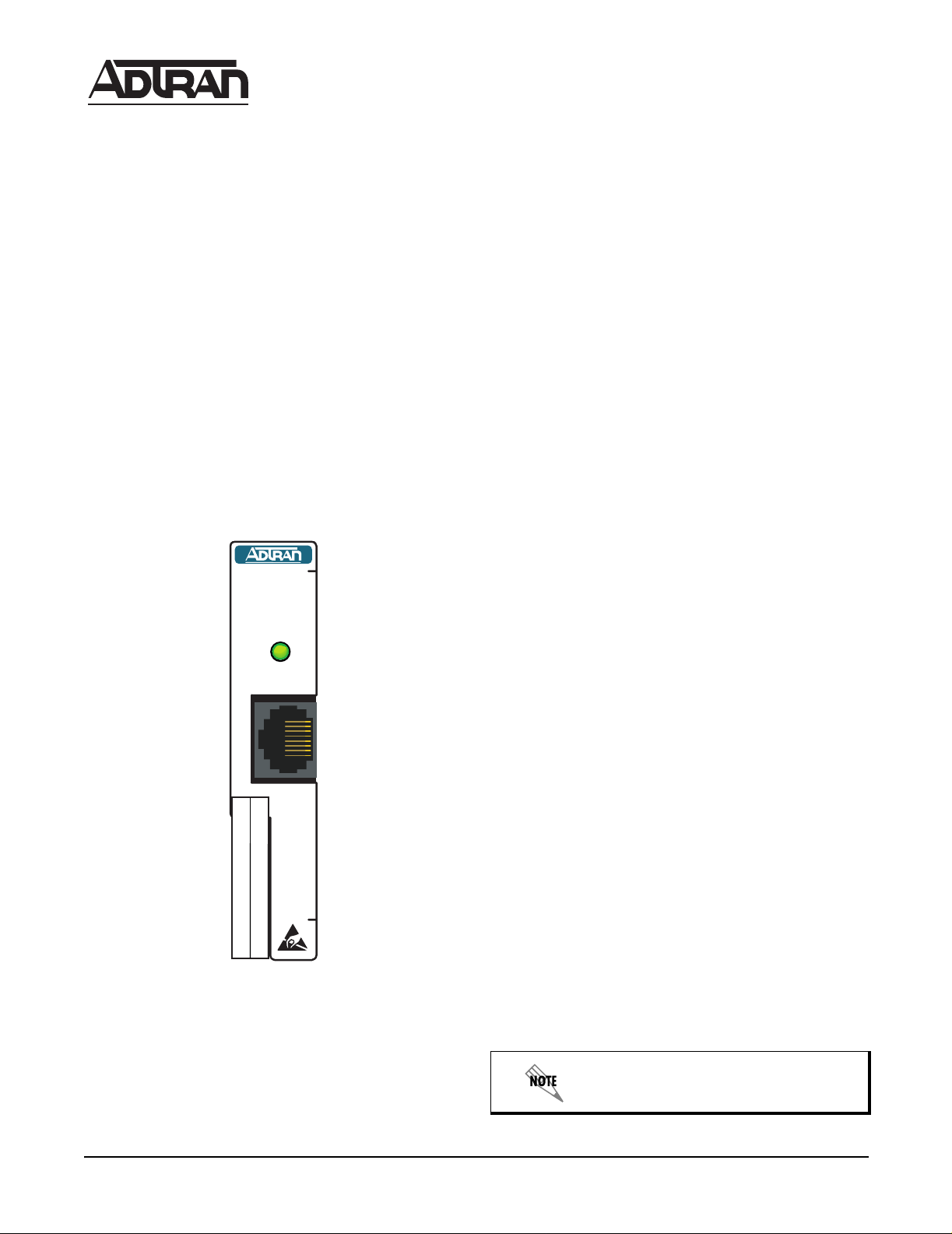
procedures for the DSX-1 M o dule (see Figure 1).
DSX-1
1200385L1
STATUS
PBXs and other equipment with DSX-1/FT1 interfaces.
The modules functions are very similar to those of the
Total Access 850 integrated DSX-1 interface.
Features
The Total Access 850 DSX-1 Module includes the following features:
• Single port, single slot module with DSX-1 interface
• Allows for support of multiple PBXs or other
equipment with DSX-1/FT1 interface
• Installs in any slot one through six
• RCU support only
Functional Description
The DSX-1 Module installs into the Total Access 850
system to provide an additional DSX-1 interface for
support of multiple PBXs or other equipment with a
DSX-1/FT1 interface. The module is functional in any
of the six slots. The DSX-1 Module is only operational
with the RCU commons.
Physical Description
The faceplate of the Total Access 850 DSX-1 Module displays the module name, part number, CL EI code and
status LEDs. The module name, part number, and CLEI
code may also be found through the terminal menus.
The dimensions of the card itself are approximately 9.5
inches x 6 inches.
3. INSTALLING THE MODULE
Carefully unpack and inspect the Total Access 850 DSX1 Module for shipping damages. If you suspect damage
has occurred during shipping, immediately file a claim
with the carrier, then contact ADTRAN Technical Support (see Warranty and Customer Service on page 4). If possible, keep the original shipping container for returning
the Total Access 850 DSX-1 Module for repair or for verification of shipping damage.
Shipping Contents
The contents include the following items:
• Total Access 850 DSX-1 Module
Figure 1. DSX-1 Module
Revision History
This is the first revision of this practice.
2. INTRODUCING THE MODULE
The Total Access 850 DSX-1 is an access module that
provides the means of supporting applications with
61200385L1-5A 1
Trademarks: Any brand names and product names included in this document are
trademarks, registered trademarks, or trade names of their respective holders.
• Total Access 850 DSX-1 Module Quick Start Guide
Instructions for Installing the Module
Follow the steps below to install the module.
Hot insertion of the module is permissible.
Page 2
Dangerous voltage is exposed when the
cover plate is removed.
The remainder of this document describes
the menu items available when managing
the Total Access 850 DSX-1 Module via
the terminal menus.
1. If present, remove the cover plate from the appropriate option slot of the Total Access 850 chassis.
2. Position the module to fit in the lower and upper
grooves.
3. Slide the module into the option slot pressing
equally on the top and bottom of the faceplate until
the module is firmly positioned against the back of
the chassis.
4. Push in the ejector on the lower left-hand side of
the module to finish seating the module.
Auto-detection of Modules
The Total Access 850 RCU automatically detects the
presence of the Total Access 850 DSX-1 Module when
the module is installed into the system. You are not required to reboot.
Wiring Connections
The Total Access 850 DSX-1 Module connects to two 64pin Champ connectors located on the backplane. (Pinouts are given in the System Manual, Section 2, Engi-
neering Guidelines.)
Faceplate LEDs
The faceplate LED colors are described below.
ONLINE LED Colors Description
Off No power present
Amber Channel test in progress
Blinking Amber Card initializing during
startup
Green DSX-1 signal present &
synchronized; channel is
configured for use
Red Channel alarm present
4. USING THE MODULE
You can configure and control the Total Access 850
DSX-1 Module from a variety of sources, including the
following:
• The terminal menus, allowing detailed configuration, status, and diagnostics via the DB-9 craft port
on the front of the card, the RJ-45 craft port on the
rear of the chassis, or telnet.
The Terminal Menus
The terminal menus are available by using either a
VT-100 terminal attached to the Total Access 850 active
RCU’s craft port, the chassis’ ADMIN port, or a Telnet
session established through the RCU’s Ethernet port.
The Total Access 850 System Manual provides detailed
instructions on using any of these management approaches.
Terminal Menu Structure
The Total Access 850 uses a hierarchical menu structure
to provide access to all of its features. The top-most
menu level leads to submenus which are grouped by
functionality. All menu items display in the terminal
window.
Accessing the Module Terminal Menus
Once you are connected to a terminal, press
eral times until a
LOGIN prompt displays. Enter the de-
Enter sev-
fault, password, in lowercase characters (the login
system is case sensitive). TheTotal Access 850 upperlevel
SYSTEM INFO menu opens.
To access the terminal menu for the Total Access 850
DSX-1 Module:
1. Use the arrow keys to navigate to the
menu and press
Enter.
MODULES
2. Select the module by using the arrow keys to highlight the specific module.
3. Press
Enter while the module slot is highlighted.
Menu options for the module now display on the terminal.
Refer to the Total Access 850 System
Manual for detailed instructions on navigating through the terminal menu.
Passwords
To edit fields in the terminal menus, you must have the
appropriate password level. Each menu description in
this section indicates the password level required for
write and read access. Security level
FULL users can
view and edit every available fie ld. Security level
STATUS users can view most fields but cannot edit.
I
NTERFACES MENU
DSX card identifies the T otal Access 850 DSX-1 Module.
The following sections describe the
options:
INTERFACE, CONFIG and TEST.
INTERFACES menu
2 Issue 1 61200385L1-5A
Page 3

INTERFACES
Write security: Config; Read security: Status
Displays either the type of module currently installed in
the slot or the type of module you plan to install in the
slot. If an Total Access 850 DSX-1 Module is installed,
the
TYPE field automatically defaults to DSX card.
T
EST
Write security: Voice; Read security: Status
Initiates different types of tests and displays test results. This menu includes the following submenu:
LOC LB
If a module is installed,
INTERFACES auto-
matically displays the name of the
installed module. To change this name,
remove the installed module, set
FACES to EMPTY and then select another
INTER-
module.
ONFIG
C
Displays additional configuration menus for the selected module. To access the submenus for this item, use
the arrow keys to scroll to the
module you want to edit, then press
CONFIG column for the
Enter. For detailed
information on each submenu item, see Total Access 850
DSX-1 Module Config Options on page 3.
Total Access 850 DSX-1 Module Config Options
The following sections describe the menus options:
CONFIG AND TEST.
C
ONFIG
Write security: Config; Read security: Status
Allows users to provision the following options for
the DSX-1 interface.
F
ORMAT
This sets the frame format for the T1 interface. The
setting must match the frame format of the circuit to
which the interface is connected. Choices are ESF
and SF. Extended Superframe (ESF) provides a nondisruptive means of full-time monitoring on the facility datalink (FDL). Default is ESF.
Configuration Path: INTERFACES (DSX-1) > CONFIG > FORMAT)
L
INE CODE
This sets the line code for the T1 interface. The setting must match the line code of the circuit to which
the interface is connected. Choices are B8ZS (bipolar
with 8-zero substitution) and AMI (alternate mark
inversion). Default is B8ZS.
Configuration Path: INTERFACES (DSX-1) > CONFIG > LINE CODE
When activated, these test command will
temporarily disrupt service.
LOC LB
Write security:
VOICE; Read security: STATUS
Causes line loopback (LB) on the near-end (local)
port. The following options are available:
•
LINE - metallic loopback
•
PAYLD - payload loopback; regenerates framing
and clocking
•
NONE - default setting which means no loopback
R
UN SELF-TEST
To run a self-test on the module, go to the SYSTEM UTILITY
menu and select
RUN SELF-TEST. This menu allows you
to run individual self-tests on all modules.
5. SPECIFICATIONS
Each port of the Total Access 850 DSX-1 Module conforms to the following specifications:
Capacity T1: 1 to 24 DS0s
Framing ESF and SF(D4)
Line Build Out DSX-1:
0 to 655 feet in 133-foot increments
Line Coding AMI (alternate mark inve rsion) or
B8ZS (bipolar 8 zero substitution)
Line Rate 1.544 Mbps, +
Relative
Up to 95% noncondensing
Humidity
Terminating
100 ohms +
Impedance
Temperature
Operate at -0
Store at -40
Tests Self-test, local line, local payload
75 bps
5%
o
C to +50oC
o
C to +70oC
SF is equivalent to the D4 frame format.
Contact ADTRAN Technical Support to
enable this feature.
61200385L1-5A Issue 1 3
Page 4

6. MAINTENANCE
The Total Access 850 DSX-1 Module requires no routine
maintenance to operate properly.
ADTRAN cautions against performing
repairs in the field. Repair services are
available if you return damaged units to
ADTRAN. Refer to the following section,
“Warranty and Customer Service,” for
further information.
7. WARRANTY AND CUSTOMER SERVICE
ADTRAN will replace or repair this product within ten
years of the date of shipment if it does not meet its published specifications or fails while in service.
Return Material Authorization (RMA) is required prior
to returning equipment to ADTRAN.
For service, RMA requests, or further information contact one of the following numbers:
ADTRAN Sales (800) 827-0807
ADTRAN Technical Support (888) 4ADTRAN
CAPS Department (256) 963-8722
Clearly identify the RMA number on the package and
return to the following address:
ADTRAN Customer and Products Service
901 Explorer Blvd.
Huntsville, AL 35806
RMA # _______________
4 Issue 1 61200385L1-5A
 Loading...