

Page 1

DSU IV ESP
Data Service Unit with Embedded SNMP
User Manual
61204011L1-1B
May 2001
Part Number
1204011L1
1204001L1
1204002L2
1204004L1
1204005L1
Version
DSU IV ESP
ESP 4-wire Switched 56 DBU Card
ESP V.34 DBU Card
ESP ISDN DBU Card
ESP Ethernet Card
Page 2

Trademark Information:
Hayes is a registered trademark of Hayes Microcomputer Products, Inc.
Openview is a registered trademark of Hewlett-Packar d Company.
SunNet Manager is a registered trademark of Sun Microsystems, Inc.
Netview is a registered trademark of IBM
901 Explorer Boulevard
P.O. Box 140000
Huntsville, AL 35814-4000
(256) 963-8000
© 2001 ADTRAN, Inc.
All Rights Reserved.
Printed in U.S.A.
Page 3
The following conventions are used in this manual.
Notes provide additional useful information.
Cautions signify information th at cou ld prevent service interruption.
Warnings provide information that could prevent damage to the
equipment or endangerment to human life.
Important Safety Instructions
When using your telephone equipment, please follow these basic safety precautions
to reduce the risk of fire, electrical shock, or personal injury:
1. Do not use this product nea r water, such as near a bathtub, wash bowl, kitchen
sink, laundry tub, in a wet basement, or near a swimming pool.
2. Avoid using a telephone (other than a cordless-type) during an electrical storm.
There is a remote risk of shock from lightning.
3. Do not use the telephone to report a gas leak in the vicinity of the leak.
4. Use only the power cord, power supply , and/or batteries indicated in the manual.
Do not dispose of batteries in a fire. They may explode. Check with local codes for
special disposal instructions.
Save These Important Safety Instructions
iii
Page 4

Affidavit Requirements for Connection to Digital Services
• An affidavit is required to be given to the telephone company whenever digital
terminal equipment without encoded analog content and billing protection is
used to transmit digital signals containing encoded analog content which are
intended for eventual conversion into voice band analog signal and transmitted
on the network.
• The affidavit shall affirm that either no encoded analog content or billing information is being transmitted or that the output of the device meets Part 68 encoded
analog content or billing protection specification.
• End use/customer will be responsible to file an affidavit with the local exchange
carrier when connecting unprotected CPE to a 1.544 Mbps or subrate digital service.
• Until such time as subrate digital terminal equipment is registered for voice applications, the affidavit requirements for subrate services are waived.
iv
Page 5

Affidavit for Connection of Customer Premises Equipment to 1.544 MBPS and/
or Subrate Digital Services
For the work to be performed in the certified territory of ______________ (telco name)
State of ________________________________
County of ______________________________
I, _______________________ (name), ____________________ (business address),
_____________________ (telephone number) being duly sworn, state:
I have the responsibility for the operation and maintenance of the terminal equipment
to be connected to 1.544 Mbps and/or __________________ subrate digital services.
The terminal equipment to be connected complies with Part 68 of the FCC rules
except for the encoded analog content and billing protection specificati on. With
respect to encoded analog content and billing protection:
( ) I attest that all opera tions associated with the establishment, maintenance and adjustment of the digital CPE with respect to encoded analog content and billing protection
information continuously complies with Pa r t 68 of the FCC rules and Regulations.
( ) The digital CPE does not transmit digital signals containing encod ed a nalog content or billing information which is in tend ed to be decoded within the telecommunications network.
( ) The encoded analog content and billing protection is factory set and is not under
the control of the customer.
I attest that the operator(s) maintainer(s) of the digital CPE responsible for the establishment, maintenance and adjustment of the encoded analog content and billing
information has (have) been trained to perform these functions by successfully having
completed one of the following (check appropriate blocks):
( ) A. A training course provided by the manufacturer/grantee of the equipment used
to encode analog signals; or
( ) B. A training course provided by the customer or authorized representative, using
training materials and instructions provided by the manufacturer/grantee of the
equipment used to encode analog signals; or
( ) C. An independent training course (e.g., trade school or technical institution) recognized by the manufacturer/grantee of the equipment used to encode analog signals; or
v
Page 6

( ) D. In lieu of the proceeding training requirements, the operator(s)/maintainer(S) is
(are) under the control of a supervisor trained in accordance with _______________
(circle one) above.
I agree to provide ____________________ (telco’s name) with proper documentation
to demonstrate compliance with the information in the preceding paragraph, if so
requested.
_______________ ______ Signature
_______________ ______ Title
_____________________ Date
Subscribed and sworn to before me
This _________ day of ___________________, 20__
_______________________________________
Notary Public
My commission expires: _________________________
vi
Page 7

FCC regulations require that the following information be provided in this manual:
1. This equipment complies with Part 68 of the FCC rules. On the bottom of the
equipment housing is a label that shows the FCC registration number and Ringer
Equivalence Number (REN) for this equipment, if applicable. If required, this
information must be given to the telepho ne company.
2. The following information may be required when applying to the local telephone
company for leased line facilities.
Service
Type
2.4 kbps Digital Interface
4.8 kbps Digital Interface
9.6 kbps Digital Interface
19.2 kbps Digital Inter face
38.4 kbps Digital Inter face
56 kbps Digital Interface
64 kbps Digital Interface
Digital Facility
Interface Code
04DU5-24
04DU5-48
04DU5-96
04DU5-19
04DU5-38
04DU5-56
04DU5-64
Service Order
Code
6.0F
6.0F
6.0F
6.0F
6.0F
6.0F
6.0F
Network
Jacks
RJ-48S
RJ-48S
RJ-48S
RJ-48S
RJ-48S
RJ-48S
RJ-48S
3. An FCC compliant telephone cord with a modular plug may be provided with
this equipment. This equipment is designed to be connected to the telephone network or premises wiring using a compatible modular jack, which is FCC Part 68
compliant. See installation instructions for details.
4. If this equipment causes harm to the telephone networ k, the telephone company
may temporarily discontinue service. If possible, advance notification is given;
otherwise, notification is given as soon as possible. The telephone company will
advise the customer of the right to file a complaint with the FCC.
5. The telephone company may make changes in its facilities, equipment, operations,
or proce d ures that could affec t th e p r ope r op er a t ion o f thi s eq ui pm e nt. If t his happens, the telephone company will provide advance notification and the opportunity
to make the necessary modifications to maintain uninterrupted service.
6. If experiencing difficulty with this equipment, please contact ADTRAN for r epair and
warranty informatio n. If the equipment is causing harm to the network, the te lephone
company may r e quest thi s e qui pme nt to b e di sc onnec te d from the network until the
problem is resolved or it is certain that the equipment is not malfunctioning.
7. This unit contains no user serviceable parts.
8. The FCC recommends that the AC outlet to which equipment requiring AC
power is to be installed is provided with an AC surge arrester.
vii
Page 8

Federal Communications Commission Radio Frequency Interference Statement
This equipment has been tested and found to comply with the limits for a Class A digital device, pursuant to Part 15 of the FCC Rules. These limits are designed to provide
reasonable protection against harmful interferen ce when the equipment is operated in
a commercial environment. This equipment generates, uses, and can radiate radio frequency energy and, if not installed and used in accordance with the instruction manual, may cause harmful interference to radio frequencies. Operation of this equipment
in a residential area is likely to cause harmful interference in which case the user will
be required to correct the interference at his own expense.
Shielded cables must be used with this unit to ensure compliance with Class A FCC
limits.
Change or modifications to this unit not expressly approved by the party responsible for complian ce c o uld void the user’s authority to operate the equipment.
Canadian Emissions Requirements
This digital apparatus does not exceed the Class A limits for radio noise emissions
from digital apparatus as set out in the interference-causing equipment standard entitled “Digital Apparatus," ICES-003 of the Department of Communications.
Cet appareil nuerique respecte les limites de bruits radioelectriques applicables aux
appareils numeriques de Class A prescrites dans la norme sur le materiel brouilleur:
"Appareils Numeriques," NMB-003 edictee par le ministre des Communications.
viii
Page 9

Canadian Equipment Limitations
Notice: The Canadian Industry and Science Canada label identifies certified equipment. This certification means that the equipment meets certain telecommunications
network protective, operational, and safety requirements. The Department does not
guarantee the equipment will operate to the user’s satisfaction.
Before installing this equipment, users should ensure that it is permissible to be connected to the facilities of the local telecommunications company . The equipment must
also be installed using an acceptable methods of connection . In so me cases, the company’s inside wiring associated with a single line individual service may be extended
by means of a certified connector assembly (telephone extension cord). The customer
should be aware that compliance with the above limitations may not prevent degradation of service in some situations.
Repairs to certified equipment should be made by an authorized Canadian maintenance facility designated by the supplier. Any repairs or alterations made by the user
to this equipment, or equipment malfunctions, may give the telecommunications
company cause to request the user to disconnect the equipment.
Users should ensure for their own protection that the electrical ground connections of
the power utility, telephone lines and internal metallic water pipe system, if present,
are connected together. This precaution may be particularly important in rural areas.
Users should not attempt to make such connections themselves,
but should contract the appropriate electric inspection authority,
or an electrician, as appropriate.
The Load Number (LN) assigned to each terminal device denotes the percentage of
the total load to be connected to a telephone loop which is used by the device, to prevent overloading. The termination on a loop may consist of any combination of
devices subject only to the requirement that the total of the Load Numbers of all
devices does not exceed 100.
ix
Page 10

ISDN Service Ordering Information for the ADTRAN DSU IV ESP with ISDN Dial
Backup
For ADTRAN DSU IV ESP ISDN applications, the following guide can be used as an
aid in ordering basic ISDN service from your local telephone company. The ADTRAN
DSU IV ESP ISDN includes NT1 and Terminal adapter function al i ty and su pports
data rates up to 64 kbps.
Request an ISDN Basic Rate Interface (BRI) line with the follo wing featur es:
• U-interface reference point
• 2BIQ line coding
• 1 B+D Service (supports up to 64 kbps)
The DSU IV ESP ISDN supports the following switch types and software protocols:
• AT&T 5ESS - Custom, 5E6 and later software, National ISDN-1
• NT DMS-100 BCS-32 and later software (Pvc1), National ISDN-1 (Pvc2)
• Siemens EQSD National ISDN-1
Request that the ISDN line allocate one DYNAMIC Terminal Endpoint Identifier (TEI)
for the number
For service offered from an AT&T 5ESS, request a point-to-point line with the following features:
•Feature: Value
•B1 Service: On Demand (DMD)
• Data Line Class: Point-to-Point
• Maximum B Chan ne ls: 1 (1B+D)
• Circuit Switched Data (CSD) Bearer Channels: Any
•Number of CSD Calls: 1 (1B+D)
•Terminal Type: Type A
x
Page 11

Turn the Following Features Off:
• Packet Mode Data
• Multi-line Hunt
• Multiple Call Appearances
• Electronic Key Telephone Sets (EKTS)
•Shared Dictionary Numbers
• Accept Special T y pe of Number
•Intercom Groups
• Network Resource Selector (Modem Pools)
•Message Waiting
•Hunting
• InterLata Competition
For Service offered from a Northern T elecom DMS-100, request a Point-to-Point MultiPoint line with the following features:
•Line Type: Basic Rate, Functional
• Electronic Key Telephone Sets (EKTS): No
• Call Appearance Handling (CACH): No
• Non-Initializing Terminal: No
• Circuit Switched Service: Yes
• Packet Switched Service: No
•TEI: Dynamic
• Bearer Service: Circuit Switched voice and data permitted on any B channel (packet
mode data not permitted).
xi
Page 12

Limited Product Warranty
ADTRAN warrants that for five (5) years from the date of shipment to Customer, all
products manufactured by ADTRAN will be free from defects in materials and workmanship. ADTRAN also warrants that products will conform to the applicable specifications and drawings for such products, as contained in the Product Manual or in
ADTRAN's internal specifications and drawings for such products (which may or
may not be reflected in the Product Manual). This warranty only applies if Customer
gives ADTRAN written notice of defects during the warranty period. Upon such
notice, ADTRAN will, at its option, either repair or replace the defective item. If ADTRAN is unable, in a reasonable time, to repair or replace any equipment to a condition
as warranted, Customer is entitled to a full refund of the purchase price upon return
of the equipment to ADTRAN. Thi s warrant y applies only to the original purchaser
and is not transferable without ADTRAN's express written permission. This warranty
becomes null and void if Customer modifies or alters the equipment in any way, other
than as specific a lly authorized by ADT RAN.
EXCEPT FOR THE LIMITED WARRANTY DESCRIBED ABOVE, THE FOREGOING
CONSTITUTES THE SOLE AND EXCLUSIVE REMEDY OF THE CUSTOMER AND
THE EXCLUSIVE LIABILITY OF ADTRAN AND IS IN LIEU OF ANY AND ALL
OTHER WARRANTIES (EXPRESSED OR IMPLIED). ADTRAN SPECIFICALLY DISCLAIMS ALL OTHER W ARR ANTIES, INCLUDING (WITHOUT LIMITATION),
ALL WARRANTIES OF MERCHANTABILITY AND FITNESS FOR A PARTICULAR
PURPOSE. SOME STATES DO NOT ALLOW THE EXCLUSION OF IMPLIED WARRANTIES, SO THIS EXCLUSION MAY NOT APPLY TO CUSTOMER.
In no event will ADTRAN or its suppliers be liable to Customer for any incidental,
special, punitive, exemplary or consequential damages experienced by either Customer or a third party (including, but not limited to, loss of data or information, loss
of profits, or loss of use). ADTRAN is not liable for damages for any cause whatsoever
(whether based in contract, tort, or otherwise) in excess of the amount paid for the
item. Some states do not allow the limitation or exclusion of liability for incidental or
consequential damages, so the above limitation or exclusion may not apply to Customer.
xii
Page 13

Customer Service, Product Support Information, and Training
ADTRAN will replace or repair this product within five years from the date of shipment if the product does not meet its published specification, or if it fails while in service.
A return material authorization (RMA) is required prior to returning equipment to
ADTRAN. For service, RMA requests, training, or more information, see the toll-free
contact numbe r s gi v e n be lo w.
Presales Inquiries and Applications Support
Please contact your local distributor, ADTRAN Applications Engineering, or ADTRAN Sales:
Applications Engineering (800) 615-1176
Sales (800) 827-0807
Post-Sale Support
Please contact your local distributor first. If your local distributor cannot help, please
contact ADTRAN Technical Support and have the unit serial number available.
Technical Support (888) 4ADTRAN
The Custom Extended Services (ACES) program offers multiple types and levels of service plans which allow you to choose the kind of assistance you need. For questions,
call the ACES Help Desk.
ACES Help Desk (888) 874-2237
xiii
Page 14

Repair and Return
If ADTRAN Technical Support determines that a repair is needed, Technical Support
will coordinate with the Custom and Product Service (CAPS) department to issue an
RMA number. For information regarding equipment currently in house or possible
fees associated with repair, contact CAPS directly at the following number:
CAPS Department (256) 963-8722
Identify the RMA number clearly on the package (below address), and return to the following address:
ADTRAN Customer and Product Service
901 Explorer Blvd.
Huntsville, Alabama 35806
RMA # _____________
Training
The Enterprise Netw or k (EN) T ec hni cal Tra ini ng Dep ar tme nt of fe rs train in g on our
most popular products. These courses include overviews on product features and functions while covering applications of ADTRAN's product lines. ADTRAN provides a variety of training options, including customized training and courses taught at our
facilities or at your site. For more information about training, please contact your Territory Manager or the Enterprise Training Coordinator.
xiv
Training - phone (800) 615-1176, ext. 7500
Training - fax (256) 963 7941
Training - email training@adtran.com
Page 15

Table of Contents
List of Figures ...................................................................................................................xxiii
List of Tables ...................................................................................................................... xxv
Chapter 1. Introduction
Product Overview ...............................................................................................................1-1
DDS Operation Overview............................................................................................1-3
Switched 56 Operation Overview..................................... ..... ...... ............................... 1-3
SNMP Overview ................................................................................................................. 1-4
Network Manager......................................................................................................... 1-4
Agent...............................................................................................................................1-4
MIB..................................................................................................................................1-4
Telnet .....................................................................................................................................1-5
Dial Backup Operation .......................................................................................................1-5
ESP Dial Backup Options............................................................................................. 1-6
4-Wire Switched 56 Card .............................................................................. 1-6
V.34 Card ........................................................................................................1-6
ISDN Card ...................................................................................................... 1-6
Chapter 2. Installation
UnPack, Inspect, Power Up ...............................................................................................2-1
ADTRAN Shipments Include......................................................................................2-1
Customer Provides ....................................................................................................... 2-2
Power Up........................................................................................................................2-2
Chapter 3. Operation
Front Panel Menu Structure .............................................................................................. 3-1
Main Menu....................................................................................................................3-1
Main Menu Descriptions .....................................................................................3-2
Status ............................................................................................................... 3-2
61204011L1-1 DSU IV ESP User Manual xv
Page 16

Table of Contents
Test ................................................................................................................... 3-2
Configuration ................................................................................................. 3-2
Dial ................................................................................................................... 3-2
Basic Menu Travel.........................................................................................................3-3
Enter .................................................................................................................3-3
Up Arrow ........................................................................................................ 3-3
Down Arrow ......................................... ......................................................... .3-3
Cancel .............................................................................................................. 3-3
Front Panel Menu Navigation .............................................................................3-4
Front Panel ...........................................................................................................................3-5
LCD Window .................................................................................................3-5
Enter .................................................................................................................3-5
Shift .................................................................................................................. 3-6
Quick ................................................................................................................3-6
Cancel .............................................................................................................. 3-6
Up and Down Arrows ................................................................................... 3-6
LED Descriptions ...........................................................................................3-6
Rear Panel .............................................................................................................................3-8
DBU and Ethernet Card Slots......................................................................................3-9
Telco Connector: Network Interface Connection.....................................................3-9
EIA-232 and V.35 Connectors: DTE Data Connection/Primary DTE.................3-10
Control Port......................................... ...... ..... ......................................................... .....3-10
VT-100 Terminal Connection And Operation ...............................................................3-11
Chapter 4. Applications
LAN Application With SNMP/Telnet Management .....................................................4-1
Minimum Configuration Requirements for SNMP/Telnet Access ...............4-3
Interface ...........................................................................................................4-3
IP Address .......................................................................................................4-3
Subnet Mask ...................................................................................................4-3
Gateway IP Address (if required) ............................................................... 4-3
Special Features of this Application ...................................................................4-3
Dial Backup Application ....................................................................................................4-4
Entering Dial Backup Mode ........................................................................................4-5
Operation During Critical Times ........................................................................4-5
Loss of Sealing Current .................................................................................4 -5
Out of Service (OOS) Signal ................................................. ...... ..... .............4-5
No Receive Signal ...................................... ....................................................4-5
All 1s or all 0s Condition ..............................................................................4-5
Answer Always ..............................................................................................4-6
Operation During Noncritical Times .................................................................4-6
xvi DSU IV ESP User Manual 61204011L1-1
Page 17

Table of Contents
Weekend and Time of Day Lockout ...........................................................4-6
Conditions for Returning to the DDS Circuit ................................................... ..... ...4-7
Chapter 5. Configuration Overview
Configuration Methods ......................................................................................................5-1
AT Commands ..............................................................................................................5-5
V.25 Bis Commands......................................................................................................5-6
SDLC Option ......................................................................................................... 5-6
Character Format ........................................................................................... 5-6
Command Structure ...................................... ................................................5-6
Bi-Sync Option ......................................................................................................5-6
Character Format ........................................................................................... 5-6
Command Structure ...................................... ................................................5-6
Asynchronous Option ..........................................................................................5-7
Character Format ........................................................................................... 5-7
Command Structure ...................................... ................................................5-7
Command Descriptions ................................................................................5-7
Syntax and Possible Responses ........................................................................... 5-8
CNL (Configuration Local) .......................................................................... 5-8
CNR (Configuration Remote) ......................................................................5-8
Chapter 6. Configuring Network Options
Network Options ................................................................................................................. 6-1
Loop Rate .......................................................................................................................6-3
Network Address..........................................................................................................6-4
Remote Configuration.................................................................................................. 6-4
Network Type........................................................................................................ ........ 6-4
Clock Source ....................................................... ...........................................................6-4
Chapter 7. Configuring DTE Options
DTE Options ........................................................................................................................ 7-1
DTE Rate......................................................................................................................... 7-5
Connector Type.............................................................................................................7-6
Data Format................................................................................................................... 7-6
DTE Command Option................................................................................................7-6
Transmit Clock .............................................................................................................. 7-7
Clear to Send (CS) Options..........................................................................................7-8
Anti-Stream....................................................................................................................7-9
CD Options ....................................................................................................................7-9
Data Terminal Ready (TR) Options............................................................................7-9
Data Set Ready (SR) Options.....................................................................................7-10
61204011L1-1 DSU IV ESP User Manual xvii
Page 18

Table of Contents
Chapter 8. Configuring Test Options
Test Options ....................................................................................................... ..................8-1
Test Timeout ..................................................................................................................8-2
Remote Digital Loopback (RDL).................................................................................8-2
EIA LLB .................................... ...... ..... ......................................................... ..... ...... .......8-3
EIA RLB.......................................... ........................................................ ...... ..... ............. 8-3
DBU Answer Test.......................................................................................................... 8-3
Chapter 9. Configuring Dial Options
Dial Options .........................................................................................................................9-1
Dial Backup Modules ..........................................................................................................9-1
Phone Numbers.............................................................................................................9 -3
ISDN Dial Backup.........................................................................................................9-3
Setting the Service Profile Identifier (SPID) ......................................................9-3
Setting the Local Directory (LDN) Number ......................................................9-3
SW56 Auto Answer.......................................................................................................9-4
DBU Options ..................................................................................................................9-4
Standard DBU Options.................................................................................................9-6
Automatic DBU .....................................................................................................9-6
Number to Dial ......................................................................................................9-6
Originate/Answer ................................................................................................ 9-6
DBU Criteria for Entering Dial Backup Mode ..................................................9-6
When Out of Service (OOS) ........................................................ ..................9-6
No Receive (RX) Signal ........................................ .........................................9-6
No Sealing Current ........................................................................................9-6
When all 1s/0s ................................................................................................9-6
Answer Always ..............................................................................................9-7
Weekend Lockout ..........................................................................................9-7
Daily Lockout .................................................................................................9-7
Lockout Start .................................................................................................. 9-7
Lockout End ....................................................................................................9-7
Auto Restore ..........................................................................................................9-7
Redial Counter .......................................................................................................9-8
Fail Timer ..................................................... ......................................................... .9-8
Wait to Redial ........................................................................................................ 9-8
DBU Options for S4W Card.........................................................................................9-8
Network Type ........................................................................................................9-8
DBU Options for V.34 Card......................................................................................... 9-9
Error Control ........................................................................................................9-10
Flow Control ........................................................................................................9-10
Compression ........................................................................................................ 9-10
xviii DSU IV ESP User Manual 61204011L1-1
Page 19

Table of Contents
DBU Options for ISDN Card.....................................................................................9-11
Switch Type ......................................................................................................... 9-11
DBU Passcode ..................................................................................................... 9-11
Chapter 10. Management Functions
Configuring Management Functions .............................................................................10-1
Interface........................................................................................................................ 10-3
Control Rate.................................................. ...... ........................................................ .10-3
IP Options .................................................................................................................... 10-3
Subnet Mask ................................................................................................. 10-3
Gateway IP Address ....................................................................................10-3
IP Security ..................................................................................................... 10-3
IP Filter Address .......................................................................................... 10-3
SNMP Options............................................................................................................. 10-4
Get Community ...........................................................................................10-4
Set Community ............................................................................................10-4
Trap Community ......................................................................................... 10-4
SNMP Traps .................................................................................................10-4
Trap IP Address ...........................................................................................10-4
System Name, Contact, and Location ....................................................... 10-5
Authentication Traps .................................................................................. 10-5
Telnet Options............................................................................................................. 10-5
Telnet Password ........................................................ ...... .............................10-5
Telnet Timeout ........................ ...... ...... ........................................................ .10-5
Entering Letters Using The Front Panel ......................................................................... 10-6
Chapter 11. Configuring Unit Utilities
Manual Command...................................................................................................... 11-3
Time/Date.................................................................................................................... 11-5
Software Revision ....................................................................................................... 11-5
LAN MAC Address.................................................................................................... 11-5
Serial Number.............................................................................................................. 11-5
Chapter 12. Activating Dial Functions
Dial Options ....................................................................................................................... 12-1
Answer Unit Connected to DDS Line .............................................................. 12-2
Dial Backup .................................................................................................. 12-2
Originate Unit Connected to DDS Line ...........................................................12-2
Dial Backup .................................................................................................. 12-2
Stay on Leased ..................................... ..... ....................................................12-2
Dial Options During Dial Backup ....................................................................12-3
61204011L1-1 DSU IV ESP User Manual xix
Page 20

Table of Contents
Hang Up .......................................... ...... ...... ..................................................12-3
Stay On Line ...................................................................................... ...... .....12-3
Chapter 13. Testing and Troubleshooting
Test Overview ....................................................................................................................13-1
Initiating a Test............................................................................................................13-2
Test Status Display......................................................................................................13-3
Exiting a Test................................................................................................................13-3
Exit Test .........................................................................................................13-3
Display Status ...............................................................................................13-4
Troubleshooting .................................................................................................................13-4
Messages from the DSU/CSU....................................................... ............................13-4
Troubleshooting New Installs...................................................................................13-6
Test Sequence for Troubleshooting New Installs or Existing Circuits ........ 13-7
Local Unit Diagnostics ......................................................... .............................................13-8
DTE & Loop (LL).......................................................................................................13-10
Test Purpose .......................................................................................................13-10
Interpreting Test Results .................................. ................................................13-10
Loop Only (RT)..........................................................................................................13-11
Test Purpose .......................................................................................................13-11
Interpreting Test Results .................................. ................................................13-11
DTE Only....................................................................................................................13-12
Test Purpose .......................................................................................................13-12
Interpreting Test Results .................................. ................................................13-12
DTE With Test Pattern..............................................................................................13-13
Test Purpose .......................................................................................................13-13
Interpreting Test Results .................................. ................................................13-14
Test Pattern ................................................................................................................13-15
Test Purpose .......................................................................................................13-15
Interpreting Test Results .................................. ................................................13-15
Self Test.......................... ..... ......................................................... ..... ..........................13-16
Test Purpose .......................................................................................................13-16
Interpreting Test Results .................................. ................................................13-16
Remote Unit Diagnostics ................................................................................................13-17
Test Purpose .......................................................................................................13-18
Initiating ............................................................................................................. 13-18
Test Results ............................................................................................... ......... 13-18
Interpreting Test Results .................................. ................................................13-18
DBU Connection ..............................................................................................................13-19
Test Purpose .......................................................................................................13-20
Initiating ............................................................................................................. 13-20
xx DSU IV ESP User Manual 61204011L1-1
Page 21

Table of Contents
Interpreting Test Results ..................................................................................13-20
Chapter 14. Viewing Status Information
Status ...................................................................................................................................14-1
Network Rate, DTE Rate, and Data Format............................................................ 14-2
Dial Backup Information............................................................................................ 14-2
Type of Dial Backup Service ............................................................................. 14-2
ISDN DBU Status .........................................................................................14-2
SW56 DBU Status ......................................................................................... 14-2
V.34 DBU Status ...........................................................................................14-2
DBU Status Not Installed ........................................................................... 14-2
Current Status of Dial Backup Mode ............................................................... 14-2
Answering Call .............................................. ...... ..... ...................................14-2
Call Disconnect ............................................................................................14-2
Called Unit Busy .......................................................................................... 14-2
Dialing ........................................................................................................... 14-3
Going to DBU ...............................................................................................14-3
Idle ................................................................................................................. 14-3
Incoming Call ....................................................... ........................................14-3
In Dial Backup ..............................................................................................14-3
No RX Signal ................................................................................................14-3
No Wink from CO ............................................... ........................................14-3
Not Installed .................................................................................................14-3
OOS/OOF From Net ................................................................................... 14-3
Open Loop ....................................................................................................14-3
DBU Line in RDL ......................................................................................... 14-3
Test From Telco ............................................................................................14-3
DBU Test Pattern ......................................................................................... 14-4
Waiting for Call ............................................................................................14-4
Inactive .......................................................................................................... 14-4
Getting TEI ........................................... ..... ...... ..............................................14-4
Register SPID ................................................................................................ 14-4
DSU Operation and Network Status ............................................................... 14-4
Current DSU IV ESP Status ........................................................................14-4
Current DDS Network Status ....................................................................14-4
DTE Control Leads and Status ..........................................................................14-5
Appendix A. Pinouts ....................................................................................................... A-1
Appendix B. AT Commands.................................................................................... ....... B-1
61204011L1-1 DSU IV ESP User Manual xxi
Page 22

Table of Contents
Appendix C. Terminal Menu Structure.......................... ...... ....................................... C-1
Appendix D. Configuration Profiles ................................................ ............................ D-1
Appendix E. DSU to DSU Tail Circuit.......................................................................... E-1
Appendix F. Specifications Summary........................................................................... F-1
Appendix G. Acronyms/Abbreviations....................................................................... G-1
Appendix H. Glossary....................................... .............................................................. H-1
Index ............................................................................................................................Index-1
xxii DSU IV ESP User Manual 61204011L1-1
Page 23

List of Figures
Figure 1-1. Typical Point-to-Point Application for DSU IV ESP .................................1-2
Figure 3-1. Main Menu LCD Display..............................................................................3-1
Figure 3-2. Example of Basic Menu Navigation............................................................ 3-4
Figure 3-3. DSU IV ESP Front Panel................................................................................3-5
Figure 3-4. DSU IV ESP Rear View..................................................................................3-8
Figure 3-5. Terminal Interface Main Menu (SW56 Mode).......................................... 3-11
Figure 4-1. SLIP/PPP LAN Application with SNMP/Telnet Management.............. 4-2
Figure 4-2. Ethernet LAN Application with SNMP/Telnet Management.................4-2
Figure 4-3. Dial Backup Application............................................................................... 4-4
Figure 5-1. Configuration Menu Tree for Network, DTE, and Test Options............. 5-3
Figure 5-2. Co nfiguration Menu Tree for Dial, Management, and Utilities Options5-4
Figure 6-1. Network Options Menu Tree........................................................................6-2
Figure 7-1. DTE Options Menu Tree................................................................................7-2
Figure 7-2. Transmit Clock Options................................................................................. 7-7
Figure 8-1. Test Options Menu Tree................................................................................. 8-1
Figure 9-1. Dial Options Configuration Menu Tree......................................................9-2
Figure 10-1. Management Menu Tree..............................................................................10-2
Figure 11-1. Utilities Menu Tree....................................................................................... 11-2
Figure 12-1. Dial Options Menu (SW56)........................... ...... ..... ...................................12-1
Figure 12-2. Dial Options Menu (Dedicated).................................... ...... ..... .................. 12-2
Figure 13-1. Normal Operation Before Initiating Loopback Test................................ 13-1
Figure 13-2. Initiating a Test .............................................................................................13-2
Figure 13-3. Sample Test Status Displays ....................................................................... 13-3
Figure 13-4. Complete Test Menu....................................................................................13-4
Figure 13-5. DTE & Loop Test ........................................................................................13-10
Figure 13-6. Loop Only Test............................................................................................ 13-11
61204011L1-1 DSU IV ESP User Manual xxiii
Page 24

List of Figures
Figure 13-7. DTE Only Test Diagram.............................................................................13-12
Figure 13-8. DTE with Test Pattern................................................................................13-13
Figure 13-9. Test Pattern Only ........................................................................................13-15
Figure 13-10.V.54 RDL with Test Pattern............................ ...... .....................................13-17
Figure 13-11.Initiating a Remote Test ............................................................................13-18
Figure 13-12.DBU Connection Test ................................................................................13-19
Figure 13-13.Initiating a DBU Connection Test................................................... ...... ...13-20
Figure 14-1. Status Display ............................................................................................... 14-1
Figure C-1. Terminal Menu Tree ......................................................................................C-2
Figure C-2. Terminal Interface Main Menu....................................................................C-3
Figure C-3. Status Menus..................................................................................................C-4
Figure C-4. Remote Configuration Options...................................................................C-5
Figure C-5. Main Configuration Menu .............................................. ............................. C-5
Figure C-6. DSU Configuration Menu............................................................................C-6
Figure C-7. S4W Dial Backup...........................................................................................C-7
Figure C-8. Management Menu.......................................................................................C-8
Figure C-9. SNMP Management Menu...........................................................................C-8
Figure C-10.Utility Menu ...................................................................................................C-9
Figure C-11.Local Test Options Menu............................................................................C-10
Figure C-12.Remote Test Options Menu........................................................................C-10
Figure C-13.SW56 Dialing Menu .................................................................................... C-11
Figure C-14.Dial ESP DBU Menu....................................................................................C-12
Figure E-1. DDS Tail Circuit..............................................................................................E-2
Figure E-2. Standard EIA-232-D Crossover Cable.........................................................E-3
xxiv DSU IV ESP User Manual 61204011L1-1
Page 25

List of Tables
Table 3-1. Front Panel LED Descriptions ...................................................................... 3-7
Table 6-1. Network Options AT Commands................................................................ 6-3
Table 7-1. DTE Options AT Commands........................................................................7-3
Table 7-2. Transmit Clock AT Commands.................................................................... 7-7
Table 7-3. Short & Long Delays at Different Operating Speeds ................................7-8
Table 8-1. Test Options AT Commands ........................................................................ 8-2
Table 9-1. AT Commands for Storing Phone Numbers.............................................. 9-3
Table 9-2. DBU Options AT Commands for All Models ............................................ 9-4
Table 9-3. DBU Options AT Commands for V.34 Card ..............................................9-9
Table 11-1. Manual Commands......................................................................................11-4
Table 13-1. Messages from the DSU/CSU .................................................................... 13-5
Table 13-2. Troubleshooting New Installs ................................................................... 13-6
Table 13-3. Test AT Commands ..................................................................................... 13-8
Table 13-4. DTE With Test Pattern Commands............................................................ 13-9
Table 13-5. Remote Tests and AT Commands............................................................ 13-17
Table A-1. Pin Assignments for Telco Connector........................................................A-2
Table A-2. Pin Assignments for ESP DBU Card Connectors .....................................A-2
Table A-3. Pin Assignments for Primary EIA-232 Connector.................................... A-3
Table A-4. Pin Assignments for Primary V.35 Connector.......................................... A-4
Table A-5. Pin Assignments for Control Connector....................................................A-5
Table A-6. Pin Assignments for 10BaseT Connector................................................... A-5
Table B-1. AT Commands................................................................................................B-1
Table B-2. DTE Options AT Commands........................................................................B-3
Table B-3. Network Options AT Commands................................................................B-6
Table B-4. Test Options AT Commands ........................................................................B-7
61204011L1-1 DSU IV ESP User Manual xxv
Page 26

List of Tables
Table B-5. AT Commands for Storing Phone Numbers ..............................................B-7
Table B-6. DBU Options AT Commands for All Models.............................................B-8
Table B-7. DBU Options AT Commands for V.34 Card ............................................B-10
Table C-1. Terminal Main Menu Dial Selection........................................................... C-3
Table D-1. Configuration Profiles...................................................................................D-2
xxvi DSU IV ESP User Manual 61204011L1-1
Page 27

Chapter 1 Introduction
PRODUCT OVERVIEW
The ADTRAN DSU IV ESP (data service unit with embedded
SNMP) provide s a reliable, high speed data connect i on for
customer data terminal equipment (DTE) through digital data
service (DDS) lines. The DSU IV ESP has an embedded SNMP
(simple network management protocol) agent that provides
complete SNMP access to the unit through an integral SLIP or PPP
async port. The DSU IV ESP's unique, modular approach provides
optional 10BaseT ethernet access for SNMP . Optional ESP DBU
cards are available to provide automatic or manual dial backup for
the dedicated circuit.
The DSU IV ESP has the following features:
• DDS rates suppor ted from 2.4 to 64 kbps including 19.2 and
38.4
• 4-wire Switched 56 (SW56) operation
• Embedded SNMP and Telnet
• Control port provides SLIP and Async PPP access to SNMP or
VT 100 terminal configuration
• Two ESP option slots
• 10BaseT ethernet SNMP port available with ESP ethernet Card
• Automatic or manual DBU
• DBU available with ESP DBU cards; options include 4-wire
Switched 56, V.34, and ISDN
• Time of day and weekend DBU lockout options
61204011L1-1 DSU IV ESP User Manual 1-1
Page 28
Chapter 1. Introduction
ERROR
DIAL
CONTROLLER
ERROR
TEST
RDL
SELECT
ERROR
SELECT
SELECT
The DSU IV ESP provides both V.35 and EIA-232 electrical and
physical DTE interfaces to accommodate a variety of applications.
To ensure a reliable connection, the unit features an extended
receiver capability which permits operation over long loops (3.4
miles or 5.5 km of 26 AWG at 56 kbps).
The ESP 4-wire SW56 DBU card and the base unit's integrated
SW56 capabilities are compatible with AT&T Accunet and Sprint
SW56 type services. The V.34 DBU card allows switched backup
over the public switched telephone network (PSTN). The ESP ISDN
1B+D card is compatible with National ISDN and supports a Uinterface to the Basic Rate ISDN.
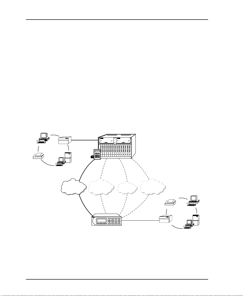
Figure 1-1 shows a typical point-to-point application for the DSU
IV ESP.
P
RINTER
PCs
BRIDGE/ROUTER
Local
Area
Network
POWER SUPPLY POWER SUPPLY
+5V
+12V
-12V
-5V
SERVER
DEDICATED
PRIVATE NETWORK
CHECK
DSU III AR DSU III AR DSU III AR DSU III AR DSU III S4W DSU III S4W DSU III S4W DSU III DBUDSU III S4W DSU III DBU DSU III DBU DSU III DBU DSU S2W DSU S2W DSU S2W
SHELF
CONTROLLER
RS
RS
RS
RS
CS
CS
CS
CS
TD
TD
TD
TD
RD
RD
RD
RD
CD
CD
CD
CD
ALM
ALM
ALM
ALM
DTE
DTE
DTE
DTE
LOOP
LOOP
LOOP
LOOP
RDL
RDL
RDL
RDL
PTRN
PTRN
PTRN
PTRN
ERROR
ERROR
ERROR
ERROR
DIALMATE
DIAL
STATUS
CANCEL
TEST CONFIG ENTER
SELECT
SELECT
SELECT
SELECT
TEST
TEST
TEST
TEST
1 2 3
4 5 6
7 8 9
0
1 16
2 3 4 5 6 7 8 9 10 11 12 13 14 15
4-wire
SW56
PUBLIC SWITCHED
DIGITAL NETWORK
4-wire
SW56
DSU IV ESP
+5V
+12V
-12V
-5V
RS
CS
TD
RD
CD
ALM
DTE
LOOP
RDL
PTRN
ERROR
SELECT
TEST
CHECK
RS
RS
RS
RS
RS
RS
RS
RS
RS
CS
CS
TD
TD
RD
RD
CD
CD
ALM
ALM
DTE
DTE
LOOP
LOOP
RDL
RDL
PTRN
PTRN
ERROR
ERROR
SELECT
SELECT
TEST
TEST
RS
CS
CS
CS
CS
CS
CS
CS
CS
TD
TD
TD
TD
TD
TD
TD
TD
RD
RD
RD
RD
RD
RD
RD
RD
CD
CD
CD
CD
CD
CD
CD
CD
ALM
ALM
ALM
ALM
ALM
ALM
ALM
ALM
DTE
DTE
DTE
DTE
DTE
DTE
DTE
DTE
LOOP
LOOP
LOOP
LOOP
LOOP
LOOP
LOOP
LOOP
RDL
RDL
RDL
RDL
RDL
RDL
RDL
RDL
PTRN
PTRN
PTRN
PTRN
PTRN
PTRN
PTRN
PTRN
ERROR
ERROR
ERROR
ERROR
ERROR
ERROR
ERROR
ERROR
SELECT
SELECT
SELECT
SELECT
SELECT
SELECT
SELECT
SELECT
TEST
TEST
TEST
TEST
TEST
TEST
TEST
TEST
MART
S
16 S
HELF
V.34
ISDN
NETWORK
DSU IV ESP
C
A
B
C
1
2
3
ENTER
D
E
F
4
5
6
7
8
9
SHIFT
QUICK
0
#
CANCEL
*
PUBLIC SWITCHED
TELEPHONE NETWORK
V.34
BRIDGE/ROUTER
RINTER
P
Local
Area
Network
Figure 1-1. Typical Point-to- Point Application for DSU IV ESP
PCs
SERVER
1-2 DSU IV ESP User Manual 61204011L1-1
Page 29

DDS Operation Overview
DDS is a nationwide service that allows interconnection and
transport of data at speeds up to 64 kbps. The local exchange
carriers provide the local loop service to DDS customers and may
provide data for routing InterLATA to an interexchange carrier. In
DDS mode, the DSU IV ESP supports 2.4 to 64 kbps DDS service
rates yielding DTE rates of 2.4, 4.8, 9.6, 19.2, 38.4 (sync or async), 56
kbps, and 64 kbps. An additional rate of 57.6 is available in
asynchronous mode. The unit can be configured to run slower DTE
rates (async or sync) over the 56 or 64 kbps service.
Switched 56 Operation Overview
This dial-up, 4-wire Switched 56 DDS allows customers to pay for
data connection only for the time the unit is active. The regional
operating companies provide the 4-wire local loop service to SW56
customers. The DSU IV ESP supports D TE rates of 2.4 , 4.8, 9.6 , 19. 2,
38.4, and 56 kbps (syn chr ono us) and 2.4 , 4.8, 9.6, 19.2, 38.4 , and 57.6
kbps (asynchronous).
Chapter 1. Introduction
61204011L1-1 DSU IV ESP User Manual 1-3
Page 30

Chapter 1. Introduction
SNMP OVERVIEW
The term SNMP broadly refers to the message protocols used to
exchange information between the network and the managed
devices, as well as to the structure of network management data
bases. SNMP has three basic components:
Network Manager
Control program that collects, controls, and presents data pertinent
to the operation of the network devices. It resides on a network
management station.
Agent
Control program that resides in each network device connected.
This program responds to queries and commands from the
network manager and returns requested information or invokes
configuration changes initiated by the manager.
MIB
Index to the o rganized data wi thin a network device. It defines the
operation parameters that can be controlled or monitored.
The DSU IV supports the MIB-II standard, RFC 1213, and
ADTRAN Enterprise Specific MIB. MIB files are available from
ADTRAN in the support section of the ADTRAN webpag e at
www.adtran.com.
The DSU IV's embedded SNMP feature allows the unit to be
accessed and controlled by a network manager through either a
device running SLIP or async PPP protocol (connected to the
CONTROL port of the DSU) or through a LAN. A LAN connection
requires the opt ional ESP ethernet card (P /N 12040 05L1). Thi s card
provides a 10BaseT ethernet interface to the LAN.
1-4 DSU IV ESP User Manual 61204011L1-1
Page 31

TELNET
Telnet provides a password-protected, remote login facility to the
DSU IV. Telnet allows a user on a network manag er to control the
DSU IV through the terminal menus. See Applications on page 4-1
and Terminal Menu Structure on page C-1 for more information.
DIAL BACKUP OPERATION
The DSU IV ESP's unique DBU cards are field-installable by the
customer. See Installation on page 2-1 for information on installing
DBU cards. All DBU car ds ar e compatible wit h other ADTRAN ESP
products supporting DBU (see the following note). The three
backup options are described in the following sections. Conta c t the
local telco provider to determine which services are available in
your area. See Applications on page 4-1 for more information,
including an example of a dial backup application.
Although the ESP V.34 DBU (P/N 1204002L2) is compatible with the
DSU IV ESP, it is not compatible with the TSU ESP (P/N 1200169L1).
Chapter 1. Introduction
61204011L1-1 DSU IV ESP User Manual 1-5
Page 32

Chapter 1. Introduction
ESP Dial Backup Options
4-Wire Switched 56 Card
The dial-up 4-wire SW56 DBU card (P/N 1204001L1) allows
customers to pay for actual usage of the data connection when the
unit is active. The regional operating companies provide 4-wire
local loop service to SW56 customers. This card supports DTE rates
of 2.4, 4.8, 9.6, 19.2, 38.4 (asynchronous or synchronous), and 56
kbps (synchronous). An additional DTE rate of 57.6 kbps is
available i n async modes.
V.34 Card
The V.34 DBU card (P/N 1204002 L2) supports V.32 bis modem
modes of operation, V.34, and V.FC modes. The V.34 option runs
synchronous rates up to 33.6 kbps, and the V.32 operates up to 14.4
kbps. Asynchronous mode provides the throughput of 57.6 kbps
and is less dependent on data types .
ISDN Card
The 1B+D Basic Rate ISDN DBU card (P/N 1204004L1) provides
the customer a backup switched 56/64 kbps ISDN circuit.
Synchronous and asynchronous DTE rates of 2.4, 4.8, 9.6, 19.2, and
38.4 kbps per CCITT V.120 are also supported. An additional DTE
rate of 57.6 kbps is available in async mode and is compatible with
the 4-wire SW56 DBU card.
The BRI DBU card (P/N 1204004L1) provides a full 2B+D BRI ISDN
service when installed in the TSU ESP or TSU IQ but only provides a one
64K bearer channel (1B+D) when installed in the DSU IV ESP.
1-6 DSU IV ESP User Manual 61204011L1-1
Page 33

Chapter 2 Installation
UNPACK, INSPECT, POWER UP
Carefully inspect the DSU IV ESP for any shipping damages. If
damage is suspected, file a claim immediately with the carrier and
contact ADTRAN Customer Service. If possible, keep the origin al
shipping container for use in shipping the DSU IV ESP for repair or
for verification of damage during shipment.
ADTRAN Shipments Include
The following items are included in ADTRAN shipments of the
DSU IV ESP :
• DSU IV ESP unit
• An 8-position modular to 8-position modular cable
• An 8-position female modular to female DB-25 adapter for
access to the Control/SLIP/PPP port
• The User Manual
The ADTRAN DSU IV ESP MIB is available from ADTRAN in th e support section of the ADTRAN webpage at www.adtran.com.
61204011L1-1 DSU IV ESP User Manual 2-1
Page 34

Chapter 2. Installation
The following items are included in ADTRAN’s shipments of ESP
DBU cards:
•ESP DBU card
• An 8-position modular to 8-position modular cable for the 4wire SW56 and 1 B+D ISDN dial backup options.
• An 8-position modular to 4-position modular cable for the V.34
backup option.
Customer Provides
The customer must provide a male EIA-232 (standard 25-pin, Dtype) or a male V.35 interface cable to use when connecting the unit
to an external data service (i.e., router).
For SNMP management, the customer must provide access to the
DSU IV ESP either through a SLIP port, Async PPP port (requires a
male 25-pin D-type connector), or a 10BaseT ethernet port (requir es
an ADTRAN ESP Ethernet card installed in the DSU IV ESP). See
Pinouts on page A-1 for the pin assignments for the control port (for
SLIP and Async PPP) and the ethernet port.
Power Up
The DSU IV ESP is provided with a captive 8-foot power cord,
terminated by a three-prong plug which connects to a grounded
115 VAC power receptacle.
Power to the DSU must be provided from a grounded 115 VAC , 60 Hz
receptacle.
2-2 DSU IV ESP User Manual 61204011L1-1
Page 35

Chapter 3 Operation
FRONT PANEL MENU STRUCTURE
The DSU IV ESP uses a multilevel menu approach to access its
many features. All menu operations are displayed in the LCD
window or the terminal. See Figure 3-5 on page 3-11 for the
terminal Main menu.
Main Menu
The following section briefly describes the main menu's four
branches, which are displayed on the front panel LCD (see Figure
3-1). Detailed information is provided in the individual chapters for
each menu branch.
1 = STATUS 2 = TEST
3 = CONFIG 4 = DIAL
Figure 3-1. Main Menu LCD Display
The opening menu is the access point to all other operations. Each
Main menu item has several functions and submenus to identify
and access specific parameters.
61204011L1-1 DSU IV ESP User Manual 3-1
Page 36

Chapter 3. Operation
Main Menu Descriptions
The branches of the front panel Main menu are divided into
options for S
Status
TATUS
S
DTE interfaces. The system returns to the S
idle. For more information, see Viewing Status Information on page
14-1.
Test
EST
Use T
REMOTE
For more information, see Te sting and Troubleshooting on page 13-1.
Configuration
Use C
parameters, configure testing and dialing options, select
management functions, and configure unit utilities.
This menu branch is divided into several chapters for easier
reference. The division includes a brief overview chapter followed
by a separate chapter for each of the six submenus: Configuring
Network Options on page 6-1, Configuring DTE Option s on page 7-1,
Configuring Test Options on page 8-1, C o nfig ur ing D ial Options on
page 9-1, Management Functions on page 10-1, and Configuring Unit
Utilities on page 11-1.
TATUS
, T
EST
, C
ONFIGURATION
(C
ONFIG
), and D
IAL
.
menu s display all re levant in formatio n for the net work and
TATUS
display when
menus to control local and remote testing. Select
LOCAL
testing, and the type of test and test pattern when required.
ONFIGURATION
menus to select network and DTE operating
or
Dial
D
IAL
provides manual dial backup or SW56 dial functions. For
more information, see Activating Dial Functions on page 12-1.
The Dial selection in the Main menu is only available when a SW56
network type is selected or when a DBU card is installed in the rear of the
DSU IV ESP.
3-2 DSU IV ESP User Manual 61204011L1-1
Page 37

Basic Menu Travel
Four function keys on the left side of the DSU IV ESP keypad allow
the various menu branches to be entered, exited, and scrolled
through. The four function keys are defined below.
Enter
Selects a displayed item.
Up Arrow
Scrolls up the submenu items.
Down Arrow
Scrolls down the submenu items.
Cancel
Exits (back one level) from the current branch of the menu.
To choose a menu item, press the corresponding number or alpha
character on the keypad (press
The item flashes on and off to show it is the currently selected
(active) choice. Press the up or down arrow keys to scroll through
the available menu items. Press
Chapter 3. Operation
to activate alpha characters).
Shift
to select the flashing item.
Enter
61204011L1-1 DSU IV ESP User Manual 3-3
Page 38

Chapter 3. Operation
Front Panel Menu Navigation
Perform the following steps to select the DSU IV ESP menu options.
See the menu tree in Figure 3-2.
Step Action
1Press 3 to activate C
2 Select L
3 Use the arrow keys to view submenu items.
4 Choose an item on the submenu such as N
5 Activate N
6 Activate L
7 Press the number corresponding to the desired loop
ONFIGURATION
(C
the activated menu item flashes, press
OCAL
or R
EMOTE
configuration by pressing
the corresponding number; then press
PTIONS
O
Enter
press
rate. Then press
(N
ETWORK OPT
.
OOP RATE
Enter.
ETWORK OPT
options by pressing 1. Then
Enter
).
by pressing 1. Then press
ONFIG
Enter.
Enter
). When
.
ETWORK
1= NETWORK OPT. 3= REMOTE CONFIG
1= LOCAL 2= DTE OPTIONS 4= NETWORK TYPE
3= CONFIG 3= TEST OPTIONS 5= CLOCK SOURCE
2= REMOTE 4= DIAL OPTIONS
5= MANAGEMENT
6 = UTILITIES
1= LOOP RATE
2= NETWORK ADDRESS
Figure 3-2. Example of Basic Menu Navigation
3-4 DSU IV ESP User Manual 61204011L1-1
Page 39

FRONT PANEL
The DSU IV ESP faceplate is shown in Figure 3-3. Descriptions of
each part of the front panel follow the figure.
LCD Window
RD LED
Up and Down Arrow Keys
ALM LED
Enter Key
ENTER
A
1
D
4
Keypad
Chapter 3. Operation
DSU IV ESP
B
2
E
5
C
3
F
6
RS LED CS LED
TD LED
CD LED
CANCEL
Cancel Key
7
SHIFT
*
Shift Key
8
0
Figure 3-3. DSU IV ESP Front Panel
LCD Window
Displays menu items and messages in 2 lines by 16 characters.
Enter
Selects active menu items. To select a menu item, press the number
of the item. The menu item flashes, indicating it is activated. Press
to select the menu item.
Enter
Keypad
The keypad conta ins dual-function keys numbered 0 through 9
with alpha characters A through F. These keys are used to activate
menu items and enter information.
9
QUICK
#
Quick Key
61204011L1-1 DSU IV ESP User Manual 3-5
Page 40

Chapter 3. Operation
Shift
before
Enter alpha characters by pressing and releasing
Shift
pressing the key representing the desired character. To activate a
menu item designated by an alpha character rather than a number
press
which parameter is activated. Press
and then the letter. The menu item flashes, indicating
Shift
to select the item.
Enter
If a key is pressed without using
Shift
, the numbered item becomes active
instead of the alpha item.
Quick
key returns the display to the
menu.
Quick
Quick
key returns to the top of the
Quick
During most operations, the
Main menu. During a test, the
EST
menu. In SW56 operations, if the unit is not in test, the
T
key returns to the D
IAL
Cancel
key stops the current activity and returns to the
Pressing the
Cancel
previous menu. Repeat until the desired menu level is re ached.
Up and Down Arrows
Up and down arrows scroll through the submenu items available in
the current menu.
LED Descriptions
The DSU IV ESP has seven LED indicators: RS, CS, TD, RD, CD,
ALM, and TST. These LEDs are described in Table 3-1 on page 3-7.
3-6 DSU IV ESP User Manual 61204011L1-1
Page 41

Chapter 3. Operation
Table 3-1. Front Panel LED Descriptions
LED Description
RS: Request to Send Reflects the status of the request to send pin of the
DTE interface.
CS: Clear to Send Reflects the status of the clear to send pin of the DTE
interface.
TD: Transmit Data This LED is active when data is transmitted from the
DTE.
RD: Receive Data This LED is active when data is received from the net-
work.
CD: Carrier Detect This LED is active when frame synchronization is
achieved and the DSU IV ESP is ready to transfer data.
ALM: Alarm Indication This LED activates whenever an alarm condition exists.
Alarm condi tions include:
Open loop on network
No frame synchronization
Unit in dial backup
Problem on dial backup line
TST: Test Mode This LED is on whenever the unit is in test mode.
61204011L1-1 DSU IV ESP User Manual 3-7
Page 42

Chapter 3. Operation
.15A
10
T
1
ON
OFF
REAR PANEL
The rear panel contains two DTE connectors whic h provide
primary channel V.35 or EIA-232. An 8-pin telco jack, a contr ol po rt,
a captive power cord, and a power switch are also located on the
rear panel. Pin assignments for these connectors are listed in
Pinouts on page A-1. The DSU IV ESP rear panel is shown in Figure
3-4 with optional ESP cards installed.
DDS
S4W, V.34, or
ISDN DBU Card
DBU INTERFACE LAN INTERFACE
ISDN
DBU
TELCO
EIA-232
10BaseT LAN Card
CONTROL
V .35
BASE
4-wire
Telco Cable
RJ45-to-DB25
EIA232 Cable
Cable
V.35 Cable
VT 100 Terminal or
device running SLIP
DTE Device DTE Device
or async PPP protocol
Item Function
DBU Interface ESP DBU card slot
LAN Interface ESP Ethernet card slot
Telco Connects to dedicated circuit
EIA-232 Connects to a DTE interfac e
Control Connects to a VT 100 terminal or a device
running SLIP or async PPP protocol
V.35 High speed DTE interface
Power Switch Tur ns power on or off
115 VAC Connection Power cord connection
Figure 3-4. DSU IV ESP Rear View
3-8 DSU IV ESP User Manual 61204011L1-1
Page 43

DBU and Ethernet Card Slots
The DSU IV ESP rear panel has two card slots for the installation of
dial backup and ethernet cards. To insert cards, perform the
following procedure:
1. Remove power from the DSU IV ESP.
2. Slide the card into the corresponding rear slot until the card
panel is flush with the DSU IV ESP chassis.
3. Push card locks in (until they click) to secure the card and
ensure proper installation.
Remove power from the unit before installing or removing ESP option
cards.
Card slots are keyed to prevent improper installation (i.e., putting a DBU
card into the ethernet slot).
Chapter 3. Operation
Telco Connector: Network Interface Connection
The DSU IV ESP has an 8-position modular jack labeled T
telco connector is used for connecting to the DDS network. The
pinout for this connector is listed in Pinouts on page A-1.
Each ESP DBU card has a connector which is used for connection to
the switched backup network. The pinout for the connector
depends on the card type. Pinouts for 4-wire Switched 56,V.34, and
ISDN 1B+D DBU options are shown in Appendix A, Pinouts on
page A-1.
61204011L1-1 DSU IV ESP User Manual 3-9
ELCO
. The
Page 44

Chapter 3. Operation
EIA-232 and V.35 Connectors: DTE Data Connection/
Primary DTE
The primary DTE should be connected to either the EIA-232 DTE
connector or the V.35 DTE connector. The maximum cable lengths
recommended are 50 feet for the EIA-232, an d 100 feet for the V.35.
The pin assignments for the connectors are listed in Pinouts on pag e
A-1.
The V.35 connector is recommended for use with data rates above
19.2 kbps. The EIA-232 connector works up to 56 kbps with a low
capacitance cable or with the external transmit clock option
selected. The primary DTE rate is configured from the front panel.
The primary DTE equipment can operate in asynchronous or
synchronous modes .
To prevent possible radio frequency interference emissions, a shielded cable is required.
Control Port
The DSU IV ESP has an 8-position modular jack labeled C
The control port provides connection to a VT 100 EIA-232
compatible interface, a device running SLIP protocol, or a device
running Async PPP protocol. An 8-foot adapter cable and
connector provide a standard DB-25 EIA-232 interface.
See Appendix A, Pinouts on page A-1 for the control port’s pin
assignments.
The control port also functions as the SLIP or Async PPP port when
configur ed for SN MP ma na geme nt. The pinou ts ar e i den tic al whe n
operating in an SNMP management mode.
3-10 DSU IV ESP User Manual 61204011L1-1
ONTROL
.
Page 45

Chapter 3. Operation
VT-100 TERMINAL CONNECTION AND OPERATION
To control the DSU IV ESP using a VT-100 terminal, perform the
following procedure:
1. Select a terminal interface through the front panel. Select
ONFIG
C
2. Set the C
3. Using the provided VT -1 00 terminal adapter cable, connect the
OM
C
eight-pin modular jack labeled C
IV ESP. This connection is used for both local and remote
configuration.
4. Establish the connection and press
ERMINAL MENU
T
ANAGEMENT
> M
ONTROL RATE
NTERFACE
> I
ERM CONTROL
>T
to match the VT 100 terminal.
.
port of a VT 100 compatible terminal or equivalent to the
ONTROL
on the rear of the DSU
repeatedly until the
Enter
appears (Figure 3-5).
Figure 3-5. Terminal Interface Main Menu (SW56 Mode)
5. Make selections by entering the number corresponding to the
SC
chosen parameter. Press E
61204011L1-1 DSU IV ESP User Manual 3-11
to return to the previous screen.
Page 46

Chapter 3. Operation
Due to the increased display capabilities, the VT-100 menu structure differs from the front panel interface. Appendix C, Terminal Menu Structure on page C-1 includes the VT-100 screens as well as a complete menu
tree for accessing configuration selections. Descriptions of individual
menu options are provided throughout this manual based on the front
panel menu stru cture. See Fig ure 5-1 on page 5- 3 and Figure 5-2 on page
5-4 for the front panel config uration menu trees.
When establishing a Telnet session, the system prompts for a password.
The default password is adtran. This password can be modified through
the Management menu. See Chapter 10, Management Functions on page
10-1 for more information.
3-12 DSU IV ESP User Manual 61204011L1-1
Page 47

Chapter 4 Applications
This chapter provides examples of some common DSU IV ESP
applications. The examples include LAN applications with both
SLIP/PPP and ethernet management and a dial backup
application.
LAN APPLICATION WITH SNMP/TELNET MANAGEMEN T
The DSU IV can be managed through an established Telnet session
or an SNMP-based network manager li ke HP Openview, IBM
Netview, or SunNet Manager.
The ADTRAN DSU IV ESP MIB is available in the support section of
the ADTRAN webpage at www.adtran.com.
SNMP and Telnet management are provided by one of the
following interfaces:
• A device (e.g., a router) running SLIP protocol. Connection is
made through the DSU IV's control port. See Figure 4-1 on page
4-2.
• A device (e.g., a router) running async PPP protocol.
Connection is made through the DSU IV's control port. See
Figure 4-1 on page 4-2.
61204011L1-1 DSU IV ESP User Manual 4-1
Page 48

Chapter 4. Applications
Figure 4-1. SLIP/PPP LAN Appli cati o n with SN MP/Telnet Management
• A LAN. Connection is made through the optional 10BaseT
ethernet interface provided on the ESP ethernet card (P/N
1204005L1). See Figure 4-2.
D
S
U
IV
A
E
S
P
B
1
C
2
D
3
E
4
T
D1
R
D1
T
D2
D
S
U
IV
A
E
S
P
B
1
C
2
D
3
E
4
T
D1
RD1
TD2
RD2
F
5
A
T
L
DN
M
NE
R
D
N
X
/
T
T
6
ST
P
R
E
V
7
A
D
D
8
S
HIF
T
9
D
E
L
E
T
E
Q
U
I
C
K
0
#
RD
F
5
2
A
T
L
DN
M
NE
R
D
N
X
/
T
T
6
ST
P
R
E
V
7
AD
D
8
S
HIF
T
9
D
E
L
E
T
E
Q
U
I
CK
0
#
LAN
SNMP
Management Station
Ethernet
Ethernet
EIA 232 or V.35
LAN
EIA 232 or V.35
Router
DDS or
Frame Relay
DSU IV ESP
A
B
1
C
2
D
3
E
4
TD1
RD1
TD2
RD2
F
5
A
T
L
DN
M
N
R
E
D
N
X
/
T
T
6
S
T
P
R
E
V
7
A
D
D
8
S
HIF
T
9
D
ELE
TE
QU
I
C
K
0
#
TD1
RD1
T
D2
DSU IV ESP
A
B
1
C
2
D
3
E
4
RD2
F
5
A
T
L
DN
M
NE
R
D
N
X
/
T
T
6
ST
P
R
E
V
7
A
D
D
8
S
HIF
T
9
D
E
L
E
T
E
Q
U
I
C
K
0
#
Router
DSU IV ESP
DSU IV ESP
Figure 4-2. Ethernet LAN Application with SNMP/Telnet Management
4-2 DSU IV ESP User Manual 61204011L1-1
Page 49

Minimum Configuration Requirements for SNMP/Telnet Access
The following options are the minimum configuration
requirements for establishing SNMP or Telnet access. Once these
options are configured, the remaining options may be configured
using SNMP/Telnet. See the menu tree in Figure 10-1 on page 10-2
for the front panel menu path to these options.
Interface
Select SLIP Control, PPP Control, or Ethernet LAN as the DSU IV
interface type. The ESP ethernet card must be installed for the
Ethernet LAN selection.
IP Address
Enter the DSU IV ESP IP address.
Subnet Mask
Enter the subnet number. This address is available from the
network administrator.
Gateway IP Address (if required)
Enter the Gateway node IP address. This address is necessary only
if the DSU IV and the network manager are connected through a
Gateway node. This address is available from the network
administrator.
Chapter 4. Applications
Special Features of this Application
Customize the SNMP/Telnet application using the following DSU
IV ESP features:
• Designate SNMP host s to r ec eive SNMP traps fro m the D SU IV
(one to five entries).
• Secure the DSU IV by limiting SNMP network management
access. If enabled, the DSU IV only responds to a userconfigur e d list of SNMP network managers (one to five
entries).
Configure these options through the Management portion of the
Configuration menu. See Chapter 10, Management Functions on
page 10-1 for more information.
61204011L1-1 DSU IV ESP User Manual 4-3
Page 50

Chapter 4. Applications
DIAL BACKUP APPLICATION
The DSU IV provides point-to-point connection to the network.
With one of the ESP DBU option cards installed, the unit is capable
of dial backup, allowing the unit to dial around a failed network.
See Figure 4-3.
With the DBU options, configure the unit to:
• Enter DBU under specific primary network conditions.
• Lock out DBU over the weekend and/or at specified times of
the day.
• Dial a specified number when a DBU activation condition is
detected.
V .34, ISDN, or 4-W ire Switched 56
Switched
Network
DTE Device
DTE Device
T
D
2
R
D2
T
D
N
DDS
DSU IV ESP
A
B
1
C
2
D
3
E
4
TD1
RD1
TD2
RD2
TDN
F
5
A
L
M
NE
R
D
N
X
/
T
T
6
ST
P
R
EV
7
A
D
D
8
S
HIF
T
9
DE
L
E
T
E
QU
I
C
K
0
#
R
F
5
A
L
M
NEXT
DN
/TST
6
PR
EV
7
AD
D
8
SHIFT
9
DE
L
E
T
E
QU
I
CK
0
#
DSU IV ESP
DSU IV ESP
A
B
1
C
2
D
3
E
4
TD1
R
D1
DSU IV ESP
Figure 4-3. Dial Backup Application
4-4 DSU IV ESP User Manual 61204011L1-1
Page 51

Entering Dial Backup Mode
When a condition for entering dial backup mode is detected, the
LARM
A
between 30 seconds on and 30 seconds off unless the DDS line is
restored or it is disabled by using the
O
information on the
Operation During Critical Times
The DSU IV ESP allows the user to select the conditions that initiate
the dial backup mode. The factory default enables DBU m ode upon
detection of these conditions. The following four conditions can
cause a DSU IV ESP to enter dial backup mode:
Loss of Sealing Current
Sealing current is a low voltage DC current provided by the central
office (CO) to prevent corrosion over the copper w ires used in the
local loop. Sealing current may also be used for local loop testing
purposes. An absence of sealing current generally is an indication
that the loop is open.
LED turns on and the buzzer sounds. The buzzer alternates
FF BEEP
. See the section Front P a ne l on page 3-5 for more
Quick
key.
Chapter 4. Applications
key and selecting T
Quick
URN
Out of Service (OOS) Signal
An OOS signal, generated by the network, indicates a device (or
devices) in the network is out of service.
No Receive Signal
This is an indication that the local loop copper pairs may be either
open or shorted or the OCU in the CO is inoperative. In a private
network this may indicate that the transmitter of the remote DSU is
inoperative.
All 1s or all 0s Condition
This condi tion is usua lly gen era ted by t he net work t o indic ate so me
device (or devic es) in t he netwo rk is in opera tive. Upon det ecting an
all 1s or all 0s condition, the DSU IV ESP initiates a handshake
routine to determine whether the remote unit's DTE is the source of
the all 1s or 0s condition or if an actual network failure exists.
61204011L1-1 DSU IV ESP User Manual 4-5
Page 52

Chapter 4. Applications
Answer Always
When this option is enabled, the unit goes into DB U mode if a call
is present regardless of the status of the dedicated circuit. It is
recommended that the DBU Passcode be used in this mode since
inadvertent calls could stop data flow indefinitely.
The DBU Answer Test is disabled if this option is chosen.
Operation During Noncritical Times
The DSU IV ESP may be configured not to enter dial backup mode
if data terminal ready (DTR) is low. This feature prevents the DSU
IV ESP from entering dial backup during noncritical times such as
nights and weekends.
For more information, see Configur ing D ial Options on page 9-1.
Weekend and Time of Day Lockout
The DSU IV ESP may be configured not to enter dial backup mode
based upon the time of day or weekend status. This protects the
customer from being charged for a switched call during off hours
should the dedicated circuit fail. See Configuring Dial Options on
page 9-1 for more information.
4-6 DSU IV ESP User Manual 61204011L1-1
Page 53

Conditions for Returning to the DDS Circuit
The DSU IV ESP can be configured to automatically revert to the
DDS circuit from the dial backup mode or wait to be returned to the
DDS manually. Once the DSU IV ESP enters dial backup mode, the
unit polls the DDS circuit once every 100 ms to determine if the
condition causing the DDS circuit failure has been corrected. Once
the DSU IV ESP determines that the problem has been properly
corrected and the DDS circuit is stable, it will wait for the amount
of time specified in the restore timer (1 to 255 minutes) before
reverting to the DDS circuit. Polling of the DDS circuit is nonintrusive and return to the DDS circuit generally takes 2 to 3
seconds. The backup connection is maintained for one minute after
the DDS circuit is restored.
See Chapter 9, Configuring Di al Options on page 9-1 for more de tai led
information.
Chapter 4. Applications
61204011L1-1 DSU IV ESP User Manual 4-7
Page 54

Chapter 4. Applications
4-8 DSU IV ESP User Manual 61204011L1-1
Page 55

Chapter 5 Configuration Overview
The DSU IV ESP contains four different user profiles (se ts of
configuration options) stored in read only memory; see
Configuration Profiles on page D-1. The unit is shipped from the
factory with profile number 1 (default configuration) loaded into
the current (nonvolatile configuration) memory . If profile 1 matches
requirements for the system, then no additional configuration is
required to put the unit into service. If profile 1 does not match
system requirements, it can be modified or one of the other profiles
that more closely matches the system requirements can be loaded
into current memory. When a different profile is loaded or the
existing profile is modified, it is stored in the current (nonvolatile
configuration) memory. The DSU IV ESP is then configured with
that profile every time power is turned on or the unit is reset.
CONFIGURATION METHODS
The DSU IV ESP responds to the following methods of
configuration:
•AT commands
• V.25 commands
•Front panel commands
• A VT 100 compatible termina l
• SNMP/Telnet through a device running SLIP/PPP protocol
• SNMP/Telnet through a LAN running ethernet protocol
(available when the optional ESP Ethernet card is installed)
61204011L1-1 DSU IV ESP User Manual 5-1
Page 56

Chapter 5. Configuration Overview
AT and V.25 commands have limited access to configuration
parameters. See AT Command s on page 5-5 and Appendix B, AT
Commands on page B-1 for more information. See Chapter 2,
Installation on page 2-1 and Chapter 3, Operation on page 3-1 for
more information on all other configuration methods. For an
example application using the SLIP/PPP or ethernet interface, see
Applications on page 4-1.
Descriptions of each Configuration menu item are given in the
following chapters: Configuring Network Options on page 6-1,
Configuring DTE Options on page 7-1, Configuring Test Options on
page 8-1, Configuring Dial Options on page 9-1, Management
Functions on page 10-1, and Configuring Unit Utilities on page 11-1.
A complete Configuration menu for the front panel is shown in
Figure 5-1 on page 5-3 and Figure 5-2 on page 5-4. The VT 100
menu tree is shown in Terminal Menu Structure on page C-1.
Due to the increased display capabilities, the VT 100 menu structure differs from the front panel interface. Appendix C, T ermi na l Menu Struc ture on page C-1 includes the VT 100 screens as well as a complete menu
tree for accessing configuration selections. Descriptions of individual
menu options are provided throughout this manual based on the front
panel menu structure. S ee Figure 5-1 on page 5-3 and Figure 5-2 on page
5-4 for the front panel configuration menu trees.
5-2 DSU IV ESP User Manual 61204011L1-1
Page 57

Chapter 5. Configuration Overview
1= Network Opt. 1= Loop Rate 1= Auto
1= Local 2= Network Addr. 1= Enter Network 3= 4.8K
Config 5= 19.2K
2= Remote Enter Addr. 2= Enabled 7= 56K
2= DTE Options 4= 19.2K
3= Remote Config 1= Disabled 6= 38.4K
4= Network Type 1= Dedicated
5= Clock Source 2= From Network
1= DTE Rate 2= 4.8K
2= Connector Type 1= EIA-232
3=Data Format 1= Asynchronous 3= Async 11 bits
4= DTE CMD Option 1= Disabled
5=Transmit Clock 1=Normal 3= V.25 Sync
6= CS Options 1= Forced On 1= CS Delay Short
7= Antistream 2= Time 10 Sec
8= CD Options 3= Off with LOCD 2= Off OOS Only
9 =TR Options - Depends on operation mode. 3= Off LOCD Only
See
Configuring DTE Options
A= SR Options 6= Off Test + LOCD
2= Address:00 4= 9.6K
2= AT&T/MCI SW56
3= US Sprint SW 56 1= Master
1= 2.4K
3= 9.6K
5= 38.4K 1=Scrambler Off
6= 56K/57.6K 2=Scrambler On
7= Same as Loop 3= Suppress LBE
2= V.35 1= Async 9 bits
2= Synchronous
2= External 4= V .25 B SC/Async
3= Invert
1= Timer Off 3= Follows CD
3= Time 30 Sec 1= Forced On
4= Time 60 Sec 2= Normal 1= Forced On
on page 7-1 for more information. 4= Off Test Only
2= 2.4K
8= 64K
2= Async 10 bits
2= AT Command Set
2= Follows RS 2= CS Delay Long
5= Off Test + OOS
1=Test Timeout Enter Timeout (0-Off): 00 Sec 1= RDL Ignored
3=Test Options
2= RDL EN/DIS 2= RDL Accepted
3= EIA LLB EN/DIS 1= Disabled
2= Enabled
4= EIA RLB EN/DIS 1= Disabled
2= Enabled 1= Disabled
5= DBU Answer Test 2= Enabled
Figure 5-1. Configuration Menu Tree for Network, DTE, and Test Options
61204011L1-1 DSU IV ESP User Manual 5-3
Page 58

Chapter 5. Configuration Overview
1= Phone Numbers Stored Number to Edit(1-10) NNNNNNN
1= Local 4= Dial Options 2= SW 56 Auto Ans 1= Disabled
Config
3= DBU Options Depends on the DBU card. See
2= Remote Enter Addr.
4= DBU Passcode 1= Enable/Disable 1= Enable
1= Interface 1= VT:100 Control
2= Control Rate 3= 9600 BPS
5= Managemen t 3= IP Options 1= Unit IP Address
4= SNMP Options 2= Set Community 1= Disable
5=Telnet Options 1= Telnet Password 1= 10 Minutes
2= Enabled
Configuring Dial Options
2= Disable
2= Enter Code XXXX
2= SLIP Control
3= PPP Control 1= 1200 BPS
4= Ethernet LAN 2= 2400 BPS
2= Subnet Mask
3= GW IP Address 1= Disabled
4= IP Security 2= Enabled
1= Get Community
3= Trap Community 2= Generic Only
4= SNMP Traps 3= Enable All
5= Trap IP Address Enter Trap IP Number (1-5):1
6= Sys Name
7= Sys Contact
8= Sys Location 1= Disabled
9= Authen Trap 2= Enabled
2= 30 Minutes
2= Telnet Timeout 3= 60 Minutes
on page 9-1
6= Utilites
1= Manual Command Command: 00 Command:HH Val ue: 00
2= Time/Date 1= Current 1= Time -23:01:59
2= Date - 08/15/01
2= Set Time 1= Set Hours
2= Set Minutes
3= Set Seconds 1= Set Month
3= Set Date 2= Set Day
3= Set Year
3= Software Rev Version CHK SUM
Rev X XXXX
4= LAN Mac Address
5= Serial Number xxxxxxxxxxxxxx
Figure 5-2. Configuration Menu Tree for Dial, Management, and Utilities Options
5-4 DSU IV ESP User Manual 61204011L1-1
Page 59

AT Commands
The DSU IV ESP can be configured and controlled with in-band A T
commands from an asynchronous DTE port just as modems are.
To exit the data mode and enter the command mode, the
asynchronous DTE device must transmit a proper escape sequence
of three pluses (+++) to the DSU IV ESP. A specified time delay
must occur between the last data character and the first escape
sequence character. This is the guard time delay, and it can be
changed by writing a value to the S12 register . The default value for
the guard time is one second. For a valid escape sequence to occur,
the DTE must transmit the escape code character three times in
succession with delay between each character being less than the
guard time.
Once the command mode is entered, AT commands can be
transmitted to the DSU IV ESP to configure most of the options or
initiate tests to check both the DSU IV ESP and the network
connections. All command lines must begin with the AT character
set in either capital or lower case letters.
Chapter 5. Configuration Overview
The command line may contain a single command or a ser ies of
commands after the AT attention code. When a series of comm ands
is used, the individ ual comma nds may b e separa ted wi th space s for
readability. The maximum length for a comma nd line is 40
characters. Each command line is executed by the DSU IV ESP
upon receipt of a terminating character. The default terminating
character is a carriage return (ASCII 013), but it can be changed by
writing a different value to register S3.
Before the terminating character is transmitted, the command line
can be edited by using the backspace character (ASCII 008) to erase
errors so the proper commands can be entered.
Not all parameters can be selected using these commands. Valid commands are listed in Appendix B, AT Commands on page B-1.
61204011L1-1 DSU IV ESP User Manual 5-5
Page 60

Chapter 5. Configuration Overview
V.25 Bis Commands
When configured for the V.25 bis option, the DSU IV ESP accepts
in-band dialing and configuration commands from both
synchronous and asynch ronou s DTE po rt s.
The V.25 bis option supports the following protocols:
•SDLC
•Bi-Sync
• Asynchronous
SDLC Option
Character Format
• Data bits - 8
•Parity bit - Ignored
Command Structure
[F][A][C][V.25 bis COMMAND][FCS][F]
The address field [A] is FFH. The control field [C] is set to 13H
except for cases of multi-frame responses. For this case, the control
field is set to 03H in all but the last frame. The 03H in the control
field indicates that other frames are to follow while the 13H in the
control field indicates the final frame.
Bi-Sync Option
Character Format
• Data bits - 7
•Parity bit - Odd
Command Structure
[SYN][SYN][STX][V.25 bis COMMAND][ETX]
5-6 DSU IV ESP User Manual 61204011L1-1
Page 61

Asynchronous Option
Character Format
• Start bit - 1
• Data bits - 7
•Parity bit - Even
• Stop bit - 1
Command Structure
[V.25 bis COMMAND][CR][LF]
Command Descriptions
The ADTRAN V.25 bis command set is a subset of the CCITT V.25
bis command set. In addition to the CCITT commands supported,
ADTRAN has added configuration commands for both local and
remote DS Us. The ADTR AN V.25 bis command set follows:
CNL Configuration local
CNR Configuration r emo te
Chapter 5. Configuration Overview
Possible responses to V.25 bis commands follows:
VALA Valid V.25 command processed
INV An invalid command de tec t ed
INVCU Unknown command detected
INVPS Invalid parameter sy nta x
INVPV Invalid parameter val ue
INVBL Invalid lo ca l pass word
INVBM Invalid remote password
If verbose responses are disabled (ATV0), the following threecharacter responses are the only ones returned:
VAL Valid V.25 command processed
INV Invalid command re ceived
61204011L1-1 DSU IV ESP User Manual 5-7
Page 62

Chapter 5. Configuration Overview
Syntax and Possible Responses
CNL (Configuration Local)
This command is used to pass AT commands to the local DSU via
the V.25 bis command processor. This allows the DSU IV ESP to be
configured with AT commands using a synchronous interface. The
format is as follows:
CNL[LOCAL PASSWORD];AT[ONE OR MORE AT COMMANDS]
A local password may not be required depending on the present
configuration of the unit . Responses to CNL commands are
returned in the data format currently configured. Possible
responses include: VALA and INVAn.
CNR (Configuration Remote)
This command is used to pass AT commands over the network to
the remote DSU via the V.25 bis command processor. This allows a
remote DSU IV ESP to be con fig ure d from a synch ronou s inte rfac e.
The format of this command follows:
CNR[REMOTE PASSWORD];AT[ONE OR MORE AT COMMANDS]
The remote password may or may not be required depending on
the present configuration of the remote unit. Responses to the CNR
commands are returned in the data format currently configured.
Possible responses include: VAL and INVAn.
5-8 DSU IV ESP User Manual 61204011L1-1
Page 63

Chapter 6 Configuring Network Options
NETWORK OPTIONS
ETWORK OPTIONS
The N
operation of the DSU IV ESP. Once a parameter is set, C
CCEPTED
A
is displayed briefly before returning to the active menu.
Table 6-1 on page 6-3 shows the AT commands used to set the
Network Options.
configuration parameters control the loop
OMMAND
See Figure 6-1 on page 6-2 for the N
61204011L1-1 DSU IV ESP User Manual 6-1
ETWORK OPTIONS
menu tree.
Page 64

Chapter 6. Configuring Network Options
1= LOCAL
CONFIG
2= REMOTE
ENTER ADDR. 4= DIAL OPTIONS 7= 6K
1= AUTO
1= LOOP RATE 2= 2.4K
1= NETWORK OPT. 3= 4 .8K
4= 9.6K
2= DTE OPTIONS 5= 19.2K
3= TEST OPTIONS 6= 38.4K
5= MANAGEMENT 8= 64K
6= UTILITIES
2= NETWORK ADDR. ENTER NETWORK
ADDRESS
3= REMOTE CONFIG 1= DISABLED
2= ENABLED
4= NETWORK TYPE 1= DEDICATED
2= AT&T/MCI SW56
3= US SPRINT SW56
5= CLOCK SOURCE 1= MASTER
2 = FROM NETWORK
Figure 6-1. Network Options Menu Tree
6-2 DSU IV ESP User Manual 61204011L1-1
Page 65

Chapter 6. Configuring Network Options
Table 6-1. Network Options AT Commands
Front Panel AT Command
Loop Rate
AUTO %B0
2.4K %B1
4.8K %B2
9.6K %B3
19.2K %B4
38.4K %B5
56K %B6
64K %B7
Network Address
XX (decimal) _N= x x
Remote Configuration
1 = DISABLED &P4
2 = ENABLED &P5
Network Type
1 = DEDICATED none
2 = AT&T/MCI SW56 none
3 = US SPRINT SW56 none
Clock Source
1 = Master _X0
2 = FROM NETWORK _X1
Loop Rate
OOP RATE
The L
should be set to the rate required by the DDS Service. The DSU IV
ESP also supports subrate DTE data over a 56 or 64 kbps loop. The
loop rate must be set independently of the DTE rate. Eight loop rate
selections are available. See Figure 6-1.
The default factory setting is A
format selections are listed in Table 6-1 on page 6-3 with the
61204011L1-1 DSU IV ESP User Manual 6-3
option sets the loop operating speed. The unit
UTO
. The various loop rates and
Page 66

Chapter 6. Configuring Network Options
equivalent AT commands that perform the same configuration
functions.
Network Address
A two-digit decimal address can be assigned to each DSU IV ESP.
This addressing capability makes it possible to perform remote
configuration and testing in point-to-point and multi-drop
networks. Figure 6-1 on page 6-2 shows the menu path used to
change the network address. The factory default setting is 0.
Remote Configuration
This option sets up the DSU IV ESP to accept or reject remote
configuration commands. The factory default setting is E
Network Type
NABLED
.
Select the appropriate network type. The choices are D
PRINT
AT&T/MCI SW56, and US S
setting is D
EDICATED
.
SW56. The factory default
EDICATED
,
Clock Source
LOCK SOURCE
The C
IV ESP’s internal circuitry. The factory default setting is F
ETWORK
N
.
When operating on a DDS network, the timing should be F
ETWORK
N
. On a point-to-point private network, one DSU IV ESP
must be set for M
When the DSU IV ESP is set to the Master Clock source, it will
default to its internal oscillators as the clock reference. T o enable the
External DTE Port as the reference clock for the circuit, see Chapter
7, Configuring DTE Options on page 7-1 regarding the transmit clock
options.
6-4 DSU IV ESP User Manual 61204011L1-1
option specifies the timing source for the DSU
ROM
ROM
ASTER
, the other set for F
ROM NETWORK
.
Page 67

Chapter 7 Configuring DTE Options
DTE OPTIONS
The DTE O
PTIONS
menu is used to select the configuration
parameters that control the operation of the DTE Interface of the
DSU IV ESP. The DTE O
PTIONS
menu tree is shown in Figure 7-1 on
page 7-2.
The AT commands and their available options are shown in Table
7-1 on page 7-3.
61204011L1-1 DSU IV ESP User Manual 7-1
Page 68

Chapter 7. Configuring DTE Options
1= 2.4K
1=DTE Rate 2= 4.8K
1=Local 1=Network Opt. 3= 9.6K
2=DTE Options 4= 19.2K
3=Test Options 5= 38.4K 1= Scrambler Off
Config 4=Dial Options 6= 56K/57.6K 2= Scrambler On
5=Management 7= Same As Loop 3= Suppress LBE
6=Utilities
2=Connector Type 1= EIA-232
2=Remote Enter Addr. 2= V.35 1= Async 9 Bits
2= Async 10 Bits
3=Data Format 1= Async 3= Async 11 Bits
2= Sync
4=DTE CMD Option 1= Disabled
2= AT Command Set
3= V.25 Sync
4= V.25 BSC/Async 1= Nor ma l
2= External
5= Transmit Clock 3= Invert
6= CS Options 1= Forced On 1= CS Delay Short
2= Follows RS 2= CS Delay Long
3= Follows CD
4= Follows RS+CD 1= CS Delay Short
5= Off with LOCD 2= CS Delay Long
7= Anti-stream 1= Timer Off
2= Time 10 Sec. 1= Ignored
3= Time 30 Sec. 1= Forced On 2= Idle When Off
4= Time 60 Sec 2= Normal 3= Off>On Dial #1
8= CD Options 3= Off with LOCD 4= Off>On Dial #2
9= TR Options 5= No DBU if Off
A= SR Options 1= Forced On
2= Off OOS Only
3= Off LOCD Only
4= Off Test Only
5= Off Test + OOS
6= Off Test + LOCD
Figure 7-1. DTE Options Menu T ree
7-2 DSU IV ESP User Manual 61204011L1-1
Page 69

Chapter 7. Configuring DTE Options
Table 7-1. DTE Options AT Commands
Front
Panel
AT
Command
Description
DTE Rate
1= 2.4K %k3 DTE Rate: 2.4K sync and async
2 = 4.8K %k4 DTE Rate: 4.8K sync and async
3 = 9.6K %k5 DTE Rate: 9.6K sync and async
4 = 19.2K %k6 DTE Rate: 19.2K sync and async
5 = 38.4K %k7 DTE Rate: 38.4K sync and async
6 = 56/57.6K %k8 DTE Rate: 56 sync or 57.6 async
7 = Same as Loop %k9 DTE Rate matches loop rate
1 = Scrambler Of f _F0 DT E data scrambler disabled (64kbps
loop rate only)
2 = Scrambler On _F1 D T E data scrambler enabled (64 kbps
loop rate only)
3 = Suppress LBE _F2 Suppresses loopback enable code (LBE)
in transmit data from the DTE after 30
bytes in a row detected (64 kbps loop rate
only)
Data Format
1= Asynchronous &Q0 Asynchronous DTE operation mode
2= Synchronous &Q2 Synchronous DTE operation mode
DTE CMD Option
1 = Disabled none Disables all DTE command Modes
2 = AT Command Set none Enables AT command mode for DTE
3 = V.25 Sync none Enables V.25 (SDLC) command mode for
DTE
4 = V.25 BSC/ASYNC none Enables V.25 (bisync or async) command
mode for DTE
Transmit Clock
1 = Normal &X0 Tx Clock from DSU selected
2 = External &X1 ETC Clock from DTE selected
3 = Invert &X3 Inverted Tx Clock from DSU selected
61204011L1-1 DSU IV ESP User Manual 7-3
Page 70

Chapter 7. Configuring DTE Options
Table 7-1. DTE Options AT Commands (Continued)
Front
Panel
AT
Command
Description
CS Options
1 = Forced On &R0 CS always on
2 = Follows RS &R1 CS state same as RS state
3 = Follows CD &R2 CS state same as CD state
4 = Follows RS+CD &R3 CS state sa me as RS and CD state
5 = Off with LOCD &R4 Off 5 seconds after LOCD (SW56 only)
For F
OLLOWS
RS options, select the length of the delay:
1 = CS delay short _D0 Short delay from RS to CS selected
2 = CS delay long _D1 Long delay from RS to CS selected
Anti-Stream
1 = Timer Off &T0 Anti-strea m timer d isabl ed
2 = Time 10 Sec &T1 T i meo ut equal s 10 secon ds
3 = Time 30 Sec &T2 T i meo ut equal s 30 secon ds
4 = Time 60 Sec &T3 T i meo ut equal s 60 secon ds
CD Options
1 - Forced On &C0 On all the time
2 - Normal &C1 On only when data present on loop
3 - Off with LOCD &C2 On except after disconnect (SW56 only)
TR Options
1 = Ignored &D0 Ignore the TR input
2 = Idle when off &D2 See the note at the end of this table.
3 = Off>On dial #1 &D3 Dial Stored #1: TR goes off to on
(SW 56 only)
4 = Off>On dial #2 &D4 Dial Stored #2: TR goes off to on
(SW 56 only)
5 = No DBU if Off & D3 No dial backu p if TR is off. (valid only
when DBU ESP card is installed and Network Type is set to Dedic ated).
7-4 DSU IV ESP User Manual 61204011L1-1
Page 71

Chapter 7. Configuring DTE Options
Table 7-1. DTE Options AT Commands (Continued)
Front
Panel
AT
Command
Description
SR Options
1 = Forced On &S0_C1 Always on
2 = Off OOS only &S1_C1 Off when network out of service
3 = Off LOCD Only &S3 Off 5 sec after disconn ect ( SW 56 onl y)
4 = Off Test only &S0_C0 Off for test only
5 = Off test + OOS &S1_C0 Off for test and OOS
6 = Off test + LOCD &S5 Off 5 seconds after disconnect or test
For
IDLE WHEN OFF
option: In SW 56 mode, TR off c a uses the DSU
to go On Hook (Idle). The unit does not dial out if TR is off. In dedicated
mode, the DSU goes into DTE command mode when TR goes off. When
TR goes on, if th e DSU does not recei ve a comman d in the nu mber of se conds set in S40, the DSU goe s into data mode.
DTE Rate
The DSU IV allows subrate looprates. If a DTE rate higher than the
current loop rate is selected, the DTE rate automatically sets to
match the slower loop rate; the DSU IV ESP briefly displays DTE
R
ATE SAME AS THE NETWORK
The factory default setting is S
before returning to the status screen.
AME AS LOOP
.
If the DSU IV ESP is set for a loop rate of 64 kbps, then scrambler
on/off options are available. The factory default setting is
S
CRAMBLER OFF
.
For 64 kbps clear channel operation, the DTE data sequences might mimic network loop maintenance functions and erroneously cause other network elements to activate loopbacks. To pr event this, the
CRAMBLER ON
S
option should be selected for both the local and remote DSU IV ESP.
61204011L1-1 DSU IV ESP User Manual 7-5
Page 72

Chapter 7. Configuring DTE Options
Connector Type
ONNECTOR TYPE
The C
primary channel connectors is used to connect to the DTE. The
factory default setting is V.35. There are no AT commands
available to set the connector type.
Data Format
ATA FORMAT
The D
asynchronous mode of operation for the DTE interface. The factory
default setting is S
length of the data bytes must be selected.
Table 7-1 on page 7-3 shows the AT commands that can be used to
set the Data Format to asynchronous or synchronous.
DTE Command Option
option is used to specify which of the
option is used to select either the synchronous or
YNCHRONOUS
SYNCHRONOUS
. If A
is chosen, the
The DTE C
OMMAND
option is u sed to enable a DTE comm and mode
or disable all modes. The available modes are AT V.25 synchronous,
and V.25 bisynchronous/asynchronous c ommands. See Table 7-1
on page 7-3.
7-6 DSU IV ESP User Manual 61204011L1-1
Page 73

Chapter 7. Configuring DTE Options
Transmit Clock
RANSMIT CLOCK
The T
used to transfer data from the DTE into the DSU IV ESP. Table 7-1
on page 7-3 shows the AT commands used to set the T
LOCK
C
options. Figure 7-2 shows the menu path used to set the
Transmit Clock option . Th e fac to ry default is N
1=LOCAL 3= DATA FORMAT
3=CONFIG 6= CS OPTIONS
2=REMOTE ENTER ADDRESS 3= TEST OPTIONS 8= CD OPTIONS
option is used to select the source of the clock
1= NETWORK OPT.
1= DTE RATE
2= DTE OPTIONS 2=C ONNECTOR TYPE
4= DTE CMD OPTION 1= NORMAL
5= TRANSMIT CLOCK 2= EXTERNAL
7= ANTI-STREAM
4= DIAL OPTIONS 9= TR OPTIONS
5= MANAGEMENT A= SR OPTIONS
6= UTILITIES
ORMAL
RANSMIT
.
Figure 7-2. Transmit Clock Options
Table 7-2 shows the A T commands used to set the T
RANSMIT CLOCK
option.
Table 7-2. Transmit Clock AT Commands
Front Panel AT Command Description
1=NORMAL &X0 TX clock from DSU selected
2=EXTERNAL &X1 ETC clock from DTE selected
The E
XTERNAL CLOCK
ASTER CLOCK
M
under DTE Options connector type. The C
ETWORK OPTIONS
N
option allows the DSU IV ESP to accept
timing from the External DTE Port as defined
must also be set to M
LOCK SOURCE
ASTER
as noted in the
under
section, Clock Source on page 6-4.
61204011L1-1 DSU IV ESP User Manual 7-7
Page 74

Chapter 7. Configuring DTE Options
XTERNAL CLOCK
The E
applications. A DSU Tail Circuit cable interconnect diagram for this
application is shown in Figure E-1 on page E-2 in Appendix E.
The E
XTERNAL CLOCK
EIA-232 connector is used for 56 kbps and 64 kbps applications.
Using this option eliminates data errors caused by excessive delays
in the DTE transmit clock receiver and transmit data driver.
The I
NVERT CLOCK
option is recommended when the EIA-232
connector is used for rates other than 56 kbps or 64 kbps.
Clear to Send (CS) Options
S OPTIONS
The C
lead. The default factory setting is F
HORT
.
S
menu is used to select the control mode for the CS
option is normally used in modem tail circuit
option is also recommended when the
OLLOWS
RS
WITH
CS D
ELAY
If one of the options chosen involves R
EQUEST TO SEND
(RS), then
the delay from RS to CS must be selected. Table 7-1 on page 7-3
shows the AT Commands used to set the CS options.
Specified times for the short and long delays at the different
operating speeds are shown in Table 7-3.
Table 7-3. Short & Long Delays at Different Operating Speeds
Rate Short Delay Long Delay
64
56
19.2
4.8
2.4
1.1 ms
1.1 ms
1.5 ms
1.5 ms
1.5 ms
16.1 ms
16.1 ms
16.5 ms
16.5 ms
16.5 ms
7-8 DSU IV ESP User Manual 61204011L1-1
Page 75

Anti-Stream
Chapter 7. Configuring DTE Options
NTI-STREAM
The A
option is used to select the anti-stream timeout.
The anti-stream timeout is the maximum time the DSU IV ESP
transmits data into the network from the DTE. This feature
prevents one DTE device on a multi-drop network from
continuously tying up the tra nsmit circuit back to the master DSU.
The anti-stream timer is reset to zero when RS changes to the active
state and is updated every second while RS is active. When the
anti-stream timeout expires, the DSU IV ESP stops transmitting
DTE data into the network b ut continues to accept data from it.
This condition exists until the DTE deactivates the RS input.
The factory default setting is T
IMER OFF
shows the available options and their AT commands.
CD Options
The CD O
receive line signal detector (CD) lead. The default factory setting is
ORMAL
N
for setting CD options.
PTIONS
menu is used to select the control mode for the
. Table 7-1 on page 7-3 shows the equivalent AT commands
Data Terminal Ready (TR) Options
The TR O
the data terminal ready (TR) lead. The factory default setting is
I
GNORED
for setting TR options.
The
is installed and the Network Type is set to DEDICATED.
PTIONS
menu is used to select the DSU IV ESP response to
. T abl e 7-1 o n page 7-3 s hows th e equivalent AT commands
NO DBU IF OFF
selection is available only when a DBU ESP card
. Table 7-1 on page 7-3
To disable DBU when DTR is off, set this option for
61204011L1-1 DSU IV ESP User Manual 7-9
IDLE WHEN OFF
.
Page 76

Chapter 7. Configuring DTE Options
Data Set Ready (SR) Options
The SR O
PTIONS
menu is used to select the operating mode for the
data set ready (SR) lead from the DTE options menu.
To activate the SR O
default setting is O
PTIONS
, press
FF TEST ONLY
Shift + A
and
Enter
. Table 7-1 on page 7-3 shows the
AT commands for setting SR options.
. The factory
7-10 DSU IV ESP User Manual 61204011L1-1
Page 77

Chapter 8 Configuring Test Options
TEST OPTIONS
EST OPTIONS
The T
and specifies the maximum test time allowed. See Figure 8-1 for the
T
EST OPTIONS
The AT commands and their available options are listed in
Table 8-1 on page 8-2.
..
1= Local 3= Test Options
Config 6= Utilities
2= Remote Ent er Addr. 3= EIA LLB EN/DIS 1= Disabled
menu enables or disables different test modes
menu tree.
1= Network Opt. E n ter Timeout
2= DTE Options 1= Test Timeout (0=Off): 00 Sec
4= Dial Options 1= RDL Ignored
5= Management 2= RDL EN/DIS 2= RDL Accepted
2= Enabled
4= EIA RLB EN/DIS 1= Disabled
2= Enabled
5= DBU Answer Test 1= Disabled
2= Enabled
Figure 8-1. Test Options Menu Tree
61204011L1-1 DSU IV ESP User Manual 8-1
Page 78

Chapter 8. Configuring Test Options
Table 8-1. Test Options AT Commands
Front
Panel
Test Timeout
Enter Timeout S18=x Specify 0 to 255 second tes t timeout
RDL Enable/Disable
1=RDL Ignored &T5 RDL request from remote DSU ignored
2= RDL Accepted &T4 RDL request accepted
EIA LLB Enable/Disable
1= Disabled _A0 No response to local loopback
2= Enabled _A1 Res pon ds to loc al loopback
EIA RLB Enable/Disable
1=Disabled _R0 No response to remote loopback
2=Enabled _R1 Res pon ds to rem ote loo pba ck
DBU Answer Test
1= Disabled none Remote unit does not accept DBU tests
2= Enabled none Remote unit accepts DBU tests from
Test Timeout
AT
Command
Description
from far end
far end
EST TIMEOUT
The T
option sets the length of time a DSU IV ESP
remains in a test mode before automatically returning to the data
mode. Enter the timeout in two-digit decimal value. The factory
OFF
default setting is
(0).
Remote Digital Loopback (RDL)
The RDL option specifies whether the DSU IV ESP responds to an
RDL request from the far end of the circuit. The factory default
setting is RDL A
8-2 DSU IV ESP User Manual 61204011L1-1
CCEPTED
.
Page 79

EIA LLB
The EIA LLB (Electronics Industries Association local loopback)
option specifies whether the DSU IV ESP responds to the local
loopback input from the DTE. The factory default setting is
D
ISABLED
EIA RLB
The EIA RLB (remote loopback) option specifies whether the DSU
IV ESP responds to the RLB input from the DTE. The factory
default setting is D
DBU Answer Test
The dial backup connection can be tested while data is passing on
the DDS. In order for this test to be performed, DBU A
must be enabled on the remote unit. If DBU A
enabled, the remote unit will not accept a DBU test from the other
end. The factory default setting is D
Chapter 8. Configuring Test Options
.
ISABLED
.
ISABLED
NSWER TEST
.
NSWER TEST
is not
The
DBU A
NSWER
A
61204011L1-1 DSU IV ESP User Manual 8-3
NSWER TEST
LWAYS
A
is not available if the
is enabled.
DBU C
RITERIA
option
Page 80

Chapter 8. Configuring Test Options
8-4 DSU IV ESP User Manual 61204011L1-1
Page 81

Chapter 9 Configuring Dial Options
DIAL OPTIONS
IAL OPTIONS
The D
disables the SW56 auto answer capability, defines the dial backup
operation when the DDS circuit fails, and programs the passcode
security feature.
Figure 9-1 on page 9-2 shows the full Dial Backup Options (4=Dial
Options) menu. Note that some items are restricted to certain DBU
cards.
menu stores up to ten phone numbers, enables/
DIAL BACKUP MODULES
The DSU IV ESP provides an optional dial backup slot in the rear of
the chassis for disaster recovery across the switched network in
case of a primary link failure. The DSU IV ESP supports the
following DBU modules:
• V.34 Analog POTS DBU (33.6Kbps; ADTRAN P/N 1204002L2)
• 4-Wire Switched 56 DBU (ADTRAN P/N 1204001L1)
• 1B+D Basic Rate ISDN (BRI) DBU (ADTRAN P/N 1204004L1)
61204011L1-1 DSU IV ESP User Manual 9-1
Page 82

Chapter 9. Configuring Dial Options
1= Phone Number Stored number to edit (1-10): NNNNNNN
1=Network Opt.
2=DTE Options 2= SW56 Auto Ans 1= Disabled
3=Test Options 2= Enabled
Config 4=Dial Options 1= Disabled
5=Management 1= Automatic DBU 2= Enabled 1= DBU with #1
6=Utilities 3= DBU Options 2= Number to Dial 2= DBU with #2
3= Origin/Answer 1= DBU Originate 1= When OOS 2= Enabled
2= DBU Answer
4= DBU Criteria 2= No RX Signal 1= Disabled
5= Auto Restore Restore Timer
0=Off: 0 Min 3= No Seal Cur. 1= Disabled
6= Redial Counter Enter Redial Count:0
7= Fail Timer Auto DBU Fail Time: 2=Enabled
0X10 Sec
8= Wait to Redial Wait to Redial 2= Enabled
Time: 0 Sec
S4W DBU Option Card 2= Enabled
Network Type AT&T/MCI/Other
US Sprint 7= Daily Lockout 1= Disabled
1= Disabled
2= Enabled
2= Enabled
4= When all 1s/0s 1=Disabled
5= Answer Always 1= Disabled
6= Weekend Lockout 1= Disabled
2= Enabled
V.34 DBU Option Card 8= Lockout Start 1= Lockout start
Error Control 1= Buffered 2= HR (0-23):xx
Flow Control 1= Disabled
Compression 1= Disabled
ISDN DBU Option Card
Switch Type 1= AT&T 5ESS 1= Enable/Disable 1= Enable
4= DBU Passcode 2= Enter Code XXXX
2= Direct
3= Reliable MNP 9= Lockout End 1= Lockout end
4= Auto MNP 2= HR (0-23):xx
5= Reliable V.42
6= Rel. V.42/MNP
7= Auto V.42/MNP
2= XOn/XOff
3= CIS only
4= RTS/CTS
5= Uni. XOn/XOff
2= Enabled
2= NT DMS-100 2= Disable
3= National ISDN
Figure 9-1. Dial Options Configuration Menu Tree
9-2 DSU IV ESP User Manual 61204011L1-1
Page 83

Phone Numbers
The DSU IV ESP stores up to 10 numbers of 36 digits each. Edit a
phone number by reentering the entire number. This process
overwrites the previously stored number.
Chapter 9. Configuring Dial Options
Table 9-1 shows the AT Commands available for the P
UMBER
N
option.
Table 9-1. AT Commands for Storing Phone Numbers
AT Command Description
&Zn= Store Phone Number
&Z9 Enter SPID Number for ISDN dial backup
&Z10= Edit LDN for ISDN dial backup
ISDN Dial Backup
Setting the Service Profile Identifier (SPID)
For ISDN dial backup, the service profile identifier (SPID) is stored
in Stored Number 9. The SPID is a sequence of digits identifying
ISDN terminal equipment to the ISDN switch when more than one
ISDN set has been attached to the same central office line. The SPID
is assigned by the telco when the ISDN line is installed and
normally resembles the phone number.
Only the AT&T 5ESS switch is capable of recognizing a point-topoint configuration, eliminating the need for a SPID. All other
switch types require a SPID.
HONE
Setting the Local Directory (LDN) Number
For ISDN dial backup, the LDN is stored in Stored Number 10.
See Table 9-1, above.
61204011L1-1 DSU IV ESP User Manual 9-3
Page 84

Chapter 9. Configuring Dial Options
SW56 Auto Answer
The SW56 Auto Answer option is used to specify how incoming
calls are to be answered. If E
automatically answered by the DSU IV. If D
call can be answered manual ly, by an AT or V.25 command from the
DTE, or by raising TR from the DTE.
DBU Options
The DBU Options are used to select the modes of operation for the
Dial Backup features. There ar e ten standar d options available w ith
additional options for specific backup services.
Table 9-2 lists the DBU options and their AT commands for all
models.
NABLED
, incoming calls are
ISABLED
, an incoming
Table 9-2. DBU Options AT Commands for All Models
Front
Panel
AT
Command
Description
Automatic DBU
1 = Disabled _K0 Automatic DBU disabled
2 = Enabled _K1 Automatic DBU enabled
Number to Dial
1 = DBU with #1 _B0 Dial stored #1
2 = DBU with #2 _B1 Dial stored #2
Originate/Answer
1 = DBU originate _E0 Originates call if DDS fails
2 = DBU answer _E1 Answers call if DDS fails
DBU Criteria
When Out of Service
1= Disabled _G0 No DBU for OOS
2 = Enabled _G1 DBU when OOS
9-4 DSU IV ESP User Manual 61204011L1-1
Page 85

Chapter 9. Configuring Dial Options
Table 9-2. DBU Options AT Commands for All Models (Continued)
Front
Panel
AT
Command
Description
No Receive (Rx) Signal
1= Disabled _H0 No D BU when RX si gna l abse nt
2 = Enabled _H1 DBU when RX signal absent
No Sealing Current
1= Disabled _I0 No DBU when sealing current absent
2 = Enabled _I0 DBU when sealing current absent
When All 1s/0s
1 = Disabled _P0 No DBU when all 1s/0s detected
2 = Enabled _P0 DBU when all 1s/0s condition exists
Answer Always
1 = Disabled none Answer unit answers only under
specified condi tio n s .
2 = Enabled none Answer unit answers any incoming
call regardless of fail e d condition.
Weekend Lockout
1 = Disabled none Disables weekend lockout feature
2 = Enabled none No backup occurs from midnight Fri-
day to midnight Sunday
Daily Lockout
1 = Disabled none Sets dial backup lockout starting hour
2 = Enabled none Sets dial backup lockout ending hour
Lockout Start none Sets hour to enable dial backup
Lockout End none Sets hour to disable dial backup
Auto Restore S31=x Sets restore timer
Redial Counter S57=x Se ts redial counter
Fail Timer S58= x Sets fail timer
Wait to Redial S59=x Sets time between redial attempts
61204011L1-1 DSU IV ESP User Manual 9-5
Page 86

Chapter 9. Configuring Dial Options
Standard DBU Options
Automatic DBU
The A
UTOMATIC
automatically enters dial backup mode or waits for manual setup.
The factory default setting is D
Number to Dial
DBU option specifies whether the unit
ISABLED
.
UMBER TO DIAL
The N
option offers a selection of stored numbers for
the unit to automatically dial. If the leased line fails, and the DSU
IV ESP is set to originate, it dials the numbers (in chronological
order) specified under this option to set up the dial backup line.
The factory default setting is D
Originate/Answer
RIGINATE/ANSWER
The O
option specifies whether the DSU IV ESP
originates or waits to answer if the dedicated circuit fails. One end
must be set to O
RIGINATE
default setting is A
and the other to A
NSWER
.
DBU Criteria for Entering Dial Backup Mode
These options specify the conditions that will cause the DSU IV ESP
to enter the backup mode.
When Out of Service (OOS)
When enabled, the DSU IV ESP enters backup mode if an out-ofservice condition is detected. The factory default setting is E
No Receive (RX) Signal
When enabled, the DSU IV ESP enters backup mode when a loss of
signal is detected. The factory default setting is E
IAL WITH
#1.
NSWER
. The factory
NABLE
.
NABLE
.
No Sealing Current
When enabled, the DSU IV ESP enters backup mode when a loss of
NABLE
sealing current is detected. The factory default setting is E
.
When all 1s/0s
When this option is enabled, the DSU IV ESP monitors the receive
data for strings of 1s or 0s that are longer than the Fail Timer. If this
9-6 DSU IV ESP User Manual 61204011L1-1
Page 87

Chapter 9. Configuring Dial Options
condition is detected, the local DSU IV ESP initiates a handshake
routine with the remote unit to determine if the DTE is generating
the constant data pattern or if the network has failed.
Answer Always
If enabled, the answer unit answers any incoming call regardless of
failed conditions.
Weekend Lockout
If enabled , no backu p will occur fr om midnig ht Fr id ay to midn ig ht
Sunday.
Weekend and daily lockout apply to automatic DBU only. Manual DBU
is not affected. Also, this parameter affects the originate end only. The
answer end remains DB U-ca pab l e a t all time s.
Daily Lockout
Enable/disable the D
H
OUR
and D
ISABLE HOUR
AILY LOCKOUT
.
specified by the fields E
NABLE
Lockout Start
Enter the hour that the daily lockout begins and dial backup is
disabled (0 to 23). Only applies if the D
NABLED
E
.
AILY LOCKOUT
parameter is
Lockout End
Enter the hour that the daily lockout ends and dial backup is
reactivated (0 to 23). Only applies if the D
is ENABLED
.
AILY LOCKOUT
parameter
Auto Restore
Once the DDS circuit is down, the DSU IV ESP remains in backup
until the DDS circuit is active for the length of time specified for the
restore timer. The selection is entered in minutes (up to 255). If set
to 0, the DDS must be restor ed manually. The factory default setting
MINUTE
is 1
RESTORE TIMER
(0=OFF): __ __ MIN
61204011L1-1 DSU IV ESP User Manual 9-7
.
Page 88

Chapter 9. Configuring Dial Options
Redial Counter
This option sets the number of times the DSU IV ESP redials the far
end when entering backup mode. The redial count, which is
manually entered, can be up to a maximum of 99 attempts. If the
DSU IV ESP encounters a busy or reorder, it attempts to establish
the call the specified number of times. The factory default setting is
5.
ENTER REDIAL
COUNT: __ __
Fail Timer
This option sets the amount of time the dedicated circuit failure
condition must be active before the DSU IV ESP attempts backup.
The amount of time, which is manually entered, can be up to 990
seconds. The factory default setting is 30
AUTO DBU FAIL
TIME: __ __ x 10sec
Wait to Redial
SECONDS
.
This option works in conjunction with the preceding Redial
Counter. It selects the amount of time between redial attempts to
connect the backup line. The amount of time, which is manually
entered, can be up to 99 seconds. The factory default setting is 10
S
ECONDS
WAIT TO REDIAL
TIME: __ __ SEC
.
DBU Options for S4W Card
Network Type
This option selects the company providing the switched digital
service. When US Sprint is selected, an automatic echo canceler
suppressor tone is emitted by the DSU IV ESP when dialing.
Options include: AT&T/MCI/O
9-8 DSU IV ESP User Manual 61204011L1-1
THER
and US S
PRINT
.
Page 89

DBU Options for V.34 Card
Chapter 9. Configuring Dial Options
Table 9-3 shows the equivalent AT commands for setting E
ONTROL
C
LOW CONTROL
, F
, and C
OMPRESSION
options.
Table 9-3. DBU Options AT Commands for V.34 Card
Front Panel AT Command Description
Error Control
1= BUFFERED \N0 Normal operation. No error control. Allo ws
speed matching, buffering, and flow control.
2= DIRECT \N1 Direct operation. No error control, no buffer,
and no flow control.
3= RELIABLE MNP \N2 Reliable MNP Ope ra tio n. Uses MNP Error
Control.
4= AUTO MNP \N3 Auto-reliable MNP operation. Tries MNP er -
ror control first; uses normal oper ati on if necessary.
5= RELIABLE V.42 \N4 Reliable V.42 (LAPM) operation. Uses V.42
(LAPM) error control. If V.42 (LAPM) error
control cannot be used the call is disconnected.
6= REL. V.42/MNP \N5 Reliable V.42 (LAPM) or MNP operation.
Uses either V.42 ( LAPM) or MNP error control. If neither can be used the call is disconnected.
7= AUTO V.42\MNP \N6 Auto-reliable V.42(LAPM) or MNP operation.
Tries to use V.42(LAPM) error control first,
and MNP error control next. If neither can be
used, then Normal operation is used.
Flow Control
1= Disabled \Q0 Flo w contr ol disabled
2= XON/XOFF \Q1 Enables XON/XOFF flow control
3= CTS ONLY \Q2 Enables CTS flow control from DCE
4= RTS/CTS \Q3 Enables CTS flow control from DCE and RTS
from DTE
5 = UNI XON/XOFF \Q4 Unidirectional XOn/XOff
RROR
61204011L1-1 DSU IV ESP User Manual 9-9
Page 90

Chapter 9. Configuring Dial Options
Table 9-3. DBU Options AT Commands for V.34 Card (Continued)
Front Panel AT Command Description
Compression
1= Disabled %C0 Compres si on disabled
2= Enabled %C1 Compres sion enabled
Error C ontrol
This option determines the type of error control to be negotiated at
the start of a V.34 modem connection. The factory default setting is
AUTO V.42/MNP.
Flow Control
This option is used to select the type of flow control used by the
V.34 modem. The factory default setting is CTS O
Compression
This option is used to select V.42 bis data compression for V.32 bis
or V.34 operation when running asynchronously. When enabled,
data throughput speeds as high as 57.6 kbps may be achieved. For
synchronous applications, the speed is limited to a maximum of
33.6 kbps for the V.34. The factory default setting is E
NLY
.
NABLED
.
9-10 DSU IV ESP User Manual 61204011L1-1
Page 91

DBU Options for ISDN Card
Switch Type
This option selects the type of telco CO switch providing the ISDN
service. There are three options for ISDN switch types:
•AT&T 5ESS
•NT DMS-100
• National ISDN
DBU Passcode
The dial backup passcode adds an additional level of security to the
DSU IV ESP. A passcode of one to ten characters can be
programmed into the unit.
When a dial backup connection is established, the originat e unit
transmits a pre-programmed passcode to the answer unit over the
dial backup connection before the connection is considered valid.
The answer unit compares the received passcode to a preprogrammed passcode. If the passcode matches, the receive unit
sends a P
line. If the passcode does not match, the receive unit sends an
Invalid Passcode message to the originate unit and terminates the
dial backup connection. If a passcode is not received by an answer
unit with passcode enable, or if the P
received by an originate unit with passcode enable, the dial backup
connection is terminated.
ASSCODE
OK message to the originate unit and goes on-
Chapter 9. Configuring Dial Options
ASSCODE
OK message is not
61204011L1-1 DSU IV ESP User Manual 9-11
Page 92

Chapter 9. Configuring Dial Options
9-12 DSU IV ESP User Manual 61204011L1-1
Page 93

Chapter 10 Management Functions
CONFIGURING MANAGEMENT FUNCTIONS
ANAGEMENT
The M
interface type and to set up the necessary parameters for
establishing Telnet or SNMP management. See Figure 10-1 on page
10- 2 for the M
menu is used to select the desired management
ANAGEMENT
menu tree.
61204011L1-1 DSU IV ESP User Manual 10-1
Page 94

Chapter 10. Management Functions
1= Network Opt.
2= DTE Options 1= Interface 1= VT 100 Control
3= Test Options 2= SLIP Control
1= Local 4= Dial Options 3= PPP Control
5= Management 4= Ethernet LAN
6= Utilities
Config 2= Control Rate 1= 1200 BPS
2= Remote Enter Address 2= 2400 BPS
3= IP Options 1= Unit IP Address
3= 9600 BPS
2= Subnet Mask
3= Gateway IP Addr 1= Disabled
4= IP Security 2= Enabled
5= IP Filter Addr Enter Source IP
Number (1-5):1
1= Get Community
4= SNMP Options 2= Set Community 1=Disable
3= Trap Community 2=Generic Only
4= SNMP Traps 3=Enable All
5= Trap IP Address 1=Enter Trap IP
6= Sys Name 2= Number (1-5):1
7= Sys Contact
8= Sys Location 1= Disabled
9= Authen Traps 2= Enabled
1= Telnet Password 1= 10 Minutes
5= Telnet Options 2= Telnet Timeout 2= 30 Minutes
3= 60 Minutes
Figure 10-1. Management Menu Tree
10-2 DSU IV ESP User Manual 61204011L1-1
Page 95

Interface
Control Rate
IP Options
Chapter 10. Management Functions
Select the management interface type (VT 100 terminal, SLIP, or
PPP) or select Ethernet LAN (ESP Ethernet card must be installed).
Select the control port operating speed to match the connected
device (this selection only applies when the in terface options is set
for VT 100 terminal, SLIP, or PPP).
When configuring the DSU IV ESP with the front panel, use
the "*" key to enter a decimal point.
Unit IP Address
Enter the DSU IV ESP IP A
DDRESS
in dotted decimal notation.
Subnet Mask
Enter the subnet number in dotted decimal notation. T his address
is available from the network administrator.
Gateway IP Address
Enter the G
ATEWAY NODE
IP A
DDRESS
in dotted decimal notation.
This address is necessary only if the DSU IV ESP and network
manager are connected through a Gateway node. If an IP packet
with an unknown IP address is received, the DSU IV ESP sends it to
the Gateway.
IP Security
Enable/disable the IP S
ECURITY
option. If enabled, the DSU IV ESP
only accepts management commands from the IP addresses (up to
5) entered into the IP F
ILTER ADDRESS
field.
IP Filter Address
Enter the IP addresses of the management stations from which the
DSU IV ESP should accept management commands. This filter
must be enabled though the IP Security field.
61204011L1-1 DSU IV ESP User Manual 10-3
Page 96

Chapter 10. Management Functions
SNMP Options
The following options must be configured when SNMP
management is used.
Get Community
For SNMP operation, view and edit the G
ET COMMUNITY
string. The
DSU IV ESP uses this string to validate SNMP Get (read) requests.
The default value is public. If using front panel entry, see the
section Entering Letters Using The Front Panel on page 10-6 for more
information.
Set Community
For SNMP operation, view and edit the S
ET COMMUNITY
string. The
DSU IV ESP uses this string to validate SNMP Set (write) requests.
The default value is private. If using front panel entry, see the
section Entering Letters Using The Front Panel on page 10-6 for more
information.
Trap Community
For SNMP operation, view and edit the T
RAP COMMUNITY
string.
The DSU IV ESP sends this string in SNMP trap messages to the
network manager. The default value is dsuiv. If using front panel
entry, see the section Entering Le t ters Using The Front Pa ne l on page
10-6 for more information.
SNMP Traps
Specify which traps the DSU IV ESP will send to the network
manager. When enabled, the DSU IV ESP sends SNMP traps to
network managers for alarm conditions. The options are D
ENERIC ONLY
G
, and E
NABLE ALL
. The G
ENERIC ONLY
option enables
ISABLE
,
the Generic Standard traps specified in the SNMP standard, RFC
1157. The A
LL
option sends both Generic Standard traps and the
enterprise-specific traps specif i ed in t he ADTR AN DS U IV ESP
MIB.
Trap IP Address
Enter up to five IP addresses of the SNMP managers to which the
DSU IV ESP should send traps.
10-4 DSU IV ESP User Manual 61204011L1-1
Page 97

System Name, Contact, and Location
These data fields are general information strings (defined in MIB-II
standard, RFC 1213) which can be stored by the user and retrieved
by the SNMP management station. If using front panel entry, see
the section Entering L et ters Using The Front Pa nel on page 10-6 for
more information.
Authentication Traps
Enable/disable the DSU IV ESP to send SNMP authentication traps
to the SNMP management station. If enabled, the DSU IV ESP
sends these traps when an SNMP request with an invalid
community name string is received.
The ADTRAN DSU IV ESP MIB is available in the support section of
the ADTRAN webpage at www.adtran.com.
Telnet Op tions
Chapter 10. Management Functions
Telnet Password
View/edit the Telnet password. If using front panel entry, see the
section Entering Letters Using The Front Panel on page 10-6 for more
information.
Telnet Timeout
Select the inactivity time limit. If the unit is idle for the designated
amount of time the unit times out, closing the Telnet session.
61204011L1-1 DSU IV ESP User Manual 10-5
Page 98

Chapter 10. Management Functions
ENTERING LETTERS USING THE FRONT PANEL
Some Management menus require the entry of letters rather than
numbers. When configuring the unit using the front panel, special
steps must be taken in order to perf orm these entries. The following
example of entering the Telnet Password illustrates this procedure:
1. Press
, then
5
Enter
to select T
ELNET OPTIONS
from the
Management menu.
2. Press
, then
1
to select TELN P
Enter
ASSWORD
.
3. Press the up arrow to delete the existing entry.
4. Press the
key. The cursor appears as an underscore ( _ ).
Shift
5. Use the up and down arrow keys to scroll to the appropriate
letter
6. When the letter displays, press
. A block cursor appears in
Shift
the next field.
7. To enter another letter, press
. The cursor again appears as
Shift
an underscore.
8. Repeat this procedure until all letters have been entered.
9. Once password entry is complete, press
Enter
.
A block cursor signifies movement from field to field. When this cursor is
active, pressing the up arrow key deletes the current entry of that field.
Pressing the down arrow key advances the cursor to the next field. An
underscore cursor signifies letter entry. When active, pressing the up and
down arrow keys scrolls the alphabet.
10-6 DSU IV ESP User Manual 61204011L1-1
Page 99

Chapter 11 Configuring Unit Utilities
TILITIES
The U
view the time and date, and view the software version, LAN MAC
address, and the unit serial number. See Figure 11-1 on page 11-2
for the U
AT commands are not available for this menu.
menu is used to enter manual commands , set and
TILITIES
menu tree.
61204011L1-1 DSU IV ESP User Manual 11-1
Page 100

Chapter 11. Configuring Unit Utilities
1= Network Opt. 1= Manual Command Command: 00 Command: HH
2= DTE Options Value:00
1=Local 3=Test Options
4= Dial Options 2= Time/Date 1= Current 1= Time=23:01:59
5= Management 2= Date=08/15/01
Config 6= Utilities
2=Remote Enter 2= Set Time 1= Set Hours
Address 2= Set Minutes
3= Set Date 1= Set Month
3= Set Seconds
2= Set Day
3= Set Year
3= Software Rev. Version Chksum
Rev X XXXX
4= LAN MAC Addr.
5= Serial Number
Figure 11-1. Utilities Menu Tree
11-2 DSU IV ESP User Manual 61204011L1-1
 Loading...