

Page 1

DSU IV ESP
Data Service Unit with Embedded SNMP
USER MANUAL
Part Number Version
1204011L1 DSU IV ESP
1204001L1 ESP 4-wire Switched 56 DBU Card
1204002L1 ESP V.34 DBU Card
1204004L1 ESP ISDN DBU Card
1204005L1 ESP Ethernet Card
61204.011L1-1A
May 1997
Page 2

Trademark Information:
Hayes is a registered trademark of Hayes Microcomputer Products, Inc.
Openview is a registered trademark of Hewlett-Packard Company.
SunNet Manager is a registered trademark of Sun Microsystems, Inc.
Netview is a registered trademark of IBM.
901 Explorer Boulevard
P.O. Box 140000
Huntsville, AL 35814-4000
Phone: (205) 963-8000
© 1997 ADTRAN, Inc.
All rights reserved.
Printed in USA.
Page 3

ABOUT THIS MANUAL
This manual is arranged so you can quickly and easily find the information you
need. The following is an overview of the contents of this manual:
• Chapter 1, Introduction, familiarizes you with DDS, Switched 56, SNMP, and
TELNET. This chapter also includes DSU IV highlights and describes the options
that may be purchased for use with the DSU.
• Chapter 2, Installation, describes the DSU connectors (pin assignments are given in
Appendix A) and provides an installation diagram.
• Chapter 3, Operation, explains how to operate your DSU using either the front
panel or a VT 100 terminal interface.
• Chapter 4, Applications, provides examples of some common DSU applications,
including network diagrams.
• Chapter 5, Configuration Overview, explains how to access the DSU configuration
menu, including information on the different configuration methods. This chapter
also provides a front panel menu tree.
• Chapters 6 through 11 provide brief explanations for selections made in the Configuration menus. These chapters are based on the front panel menu branches of
the Configuration menu: Network Options, DTE Options, Test Options, Dial
Options, Management, and Utilities.
• Chapter 12, Testing and Troubleshooting, describes the testing options available
with the DSU IV and gives troubleshooting information.
• Chapter 13, Activating Dial Functions, describes the Dial options available from the
Main menu.
• Chapter 14, Viewing Status Information, provides information on the status menus
available for the base unit as well as the DBU cards.
• Appendix A provides pinouts for the connectors of the DSU and the DBU and
Ethernet cards.
• Appendix B shows the AT commands available for the DSU.
• Appendix C describes the terminal menu interface (accessed through a VT 100
terminal or a TELNET session).
Page 4

• Appendix D provides information on the unit's configuration profiles.
• Appendix E contains a DSU to modem interconnect diagram for a modem tail
circuit application.
• Appendix F contains product specifications.
Notes provide additional useful information.
Cautions signify information that could prevent service interruption.
Warnings provide information that could prevent damage to the
equipment or endangerment to human life.
Page 5

FCC regulations require that the following information be provided in this manual:
1. This equipment complies with Part 68 of the FCC rules. On the bottom of the equipment
housing is a label that shows the FCC registration number and ringer equivalence number
(REN) for this equipment. If requested, provide this information to the telephone company.
2. If this equipment causes harm to the telephone network, the telephone company may temporarily
discontinue service. If possible, advance notification is given; otherwise, notification is given
as soon as possible. The telephone company will advise the customer of the right to file a
complaint with the FCC.
3. The telephone company may make changes in its facilities, equipment, operations, or
procedures that could affect the proper operation of this equipment; advance notification and
the opportunity to maintain uninterrupted service are given.
4. If experiencing difficulty with this equipment, please contact ADTRAN for repair and
warranty information. The telephone company may require this equipment to be
disconnected from the network until the problem is corrected, or it is certain the equipment is
not malfunctioning.
5. This unit contains no user-serviceable parts.
6. An FCC compliant telephone cord with a modular plug is provided with this equipment. In
addition, an FCC compliant cable appropriate for the dial backup option ordered is provided
with this equipment. This equipment is designed to be connected to the telephone network or
premises wiring using an FCC compatible modular jack, which is Part 68 compliant.
7. The following information may be required when applying to the local telephone company for
leased line facilities:
Service Digital Facility Service Order Network
Type Interface Code Code Jacks
2.4 kbps Digital Interface 04DU5-24 6.0F RJ-48S
4.8 kbps Digital Interface 04DU5-48 6.0F RJ-48S
9.6 kbps Digital Interface 04DU5-96 6.0F RJ-48S
19.2 kbps Digital Interface 04DU5-19 6.0F RJ-48S
38.4 kbps Digital Interface 04DU5-38 6.0F RJ-48S
56 kbps Digital Interface 04DU5-56 6.0F RJ-48S
64 kbps Digital Interface 04DU5-64 6.0F RJ-48S
8. The following information may be required when applying to the local telephone company for
a dial-up line for the V.34:
Service REN FIC USOC
Type
Loop Start (V.34) 0.8B/0.4A 02LS2 RJ-11C
9. The REN is useful in determining the quantity of devices you may connect to your telephone
line and still have all of those devices ring when your number is called. In most areas, the sum
of the RENs of all devices should not exceed five. To be certain of the number of devices you
may connect to your line as determined by the REN, call your telephone company to
determine the maximum REN for your calling area.
10.This equipment may not be used on coin service provided by the telephone company.
Connection to party lines is subject to state tariffs. (Contact your state public utility
commission or corporation commission for information.)
Page 6

FEDERAL COMMUNICATIONS COMMISSION
RADIO FREQUENCY INTERFERENCE STATEMENT
This equipment has been tested and found to comply with the limits for a Class A digital
device, pursuant to Part 15 of the FCC rules. These limits are designed to provide reasonable protection against harmful interference when the equipment is operated in a commercial
environment. This equipment generates, uses, and can radiate radio frequency energy and,
if not installed and used in accordance with the instruction manual, may cause harmful
interference to radio frequencies. Operation of this equipment in a residential area is likely
to cause harmful interference in which case the user will be required to correct the interference at his own expense.
Shielded cables must be used with this unit to ensure compliance with Class A FCC limits.
Change or modifications to this unit not expressly approved by the
party responsible for compliance could void the user's authority to
operate the equipment.
CANADIAN EMISSIONS REQUIREMENTS
This digital apparatus does not exceed the Class A limits for radio noise emissions
from digital apparatus as set out in the interference-causing equipment standard
entitled "Digital Apparatus," ICES-003 of the Department of Communications.
Cet appareil nuerique respecte les limites de bruits radioelectriques applicables aux
appareils numeriques de Class A prescrites dans la norme sur le materiel brouilleur:
"Appareils Numeriques," NMB-003 edictee par le ministre des Communications.
Page 7

CANADIAN EQUIPMENT LIMITATIONS
Notice: The Canadian Industry and Science Canada label identifies certified
equipment. This certification means that the equipment meets certain telecommunications network protective, operational, and safety requirements. The
Department does not guarantee the equipment will operate to the user's satisfaction.
Before installing this equipment, users should ensure that it is permissible to be
connected to the facilities of the local telecommunications company. The equipment must also be installed using an acceptable method of connection. In some
cases, the company's inside wiring associated with a single line individual
service may be extended by means of a certified connector assembly (telephone
extension cord). The customer should be aware that compliance with the above
conditions may not prevent degradation of service in some situations.
Repairs to certified equipment should be made by an authorized Canadian
maintenance facility designated by the supplier. Any repairs or alterations made
by the user to this equipment, or equipment malfunctions, may give the telecommunications company cause to request the user to disconnect the equipment.
Users should ensure for their own protection that the electrical ground connections of the power utility, telephone lines and internal metallic water pipe
system, if present, are connected together. This precaution may be particularly
important in rural areas.
Caution: Users should not attempt to make such connections themselves, but
should contact the appropriate electric inspection authority, or an electrician, as
appropriate.
The Load Number (LN) assigned to each terminal device denotes the percentage
of the total load to be connected to a telephone loop which is used by the device,
to prevent overloading. The termination on a loop may consist of any combination of devices subject only to the requirement that the total of the Load Numbers of all devices does not exceed 100.
Page 8

ISDN Service Ordering Information for the ADTRAN DSU IV ESP With ISDN Dial
Backup
For ADTRAN DSU IV ESP ISDN applications, the following guide can be used as
an aid in ordering basic ISDN service from your local telephone company. The
ADTRAN DSU IV ESP ISDN includes NT1 and Terminal adapter functionality and
supports data rates up to 64 kbps.
Request an ISDN Basic Rate Interface (BRI) line with the following features:
U-interface reference point
2B1Q line coding
1B+D Service (supports up to 64 kbps)
The DSU IV ESP ISDN supports the following switch types and software
protocols:
AT&T 5ESS Custom, 5E6 and later software, National ISDN-1
NT1 DMS-100 BCS-32 and later software (Pvc1), National ISDN-1 (Pvc2)
Siemens EWSD National ISDN-1
Request that the ISDN line allocate one DYNAMIC Terminal Endpoint Identifier
(TEI) for the number.
For service offered from an AT&T 5ESS, request a point-to-point line with the
following features:
Feature: Value
B1 Service: On Demand (DMD)
Data Line Class: Point-to-Point
Maximum B Channels: 1 (1B+D)
Circuit Switched Data (CSD) Bearer Channels: Any
Number of CSD Calls: 1 (1B+D)
Terminal Type: Type A
Page 9

Turn the Following Features Off:
Packet Mode Data
Multi-line Hunt
Multiple Call Appearances
Electronic Key Telephone Sets (EKTS)
Shared Dictionary Numbers
Accept Special Type of Number
Intercom Groups
Network Resource Selector (Modem Pools)
Message Waiting
Hunting
InterLata Competition
For service offered from a Northern Telecom DMS-100, request a Point-to-Point
Multi-Point line with the following features:
Line Type: Basic Rate, Functional
Electronic Key Telephone Sets (EKTS): No
Call Appearance Handling (CACH): No
Non-Initializing Terminal: No
Circuit Switched Service: Yes
Packet Switched Service: No
TEI: Dynamic
Bearer Service: Circuit Switched voice and data permitted on any B channel (packet mode
data not permitted)
Page 10

Table of Contents
Page 11

Table of Contents
Table of Contents
Chapter 1. Introduction
Product Overview .................................................................................................................. 1
DDS Operation ........................................................................................................................ 3
Switched 56 Operation ...........................................................................................................4
SNMP ....................................................................................................................................... 4
Network Manager ............................................................................................. 4
Agent................................................................................................................... 4
MIB ...................................................................................................................... 4
TELNET.................................................................................................................................... 5
Dial Backup Operation .......................................................................................................... 5
ESP Dial Backup Options ............................................................................................... 5
4-Wire Switched 56 Card ........................................................................................ 5
V.34 Card ................................................................................................................... 6
ISDN Card ................................................................................................................. 6
Warranty and Customer Service .......................................................................................... 6
Chapter 2. Installation
Unpack, Inspect, Power Up................................................................................................... 7
Receipt Inspection ........................................................................................................... 7
ADTRAN Shipments Include ................................................................................. 7
Customer Provides................................................................................................... 8
Power Up .......................................................................................................................... 8
Rear Panel ................................................................................................................................ 9
DBU and Ethernet Card Slots ...................................................................................... 10
Telco Connector ............................................................................................................. 10
Network Interface Connection .................................................................................... 10
EIA-232 and V.35 Connectors ...................................................................................... 10
DTE Data Connection/Primary DTE ......................................................................... 10
Control Port ....................................................................................................................11
Chapter 3. Operation
Front Panel............................................................................................................................. 13
LCD Window................................................................................................... 13
Enter .................................................................................................................. 13
Keypad.............................................................................................................. 13
Shift ................................................................................................................... 13
61204.011L1-1 DSU IV ESP User Manual i
Page 12

Table of Contents
Cancel ............................................................................................................... 14
Up and Down Arrows .................................................................................... 14
LED Descriptions ............................................................................................ 14
Front Panel Menu Navigation ..................................................................................... 17
Front Panel Menu Structure......................................................................................... 18
Main Menu .............................................................................................................. 18
Status................................................................................................................. 18
Test .................................................................................................................... 18
Configuration .................................................................................................. 19
Dial .................................................................................................................... 19
VT 100 Terminal Connection and Operation .................................................................... 20
Chapter 4. Applications
LAN Application with SNMP/TELNET Management .................................................. 23
Minimum Configuration Requirements for SNMP/TELNET Access................... 24
Interface ............................................................................................................ 24
IP Address ........................................................................................................ 24
Subnet Mask..................................................................................................... 24
Gateway IP Address (if required) ................................................................. 24
Special Features of this Application ........................................................................... 24
Dial Backup Application...................................................................................................... 26
Entering Dial Backup Mode......................................................................................... 26
Operation During Critical Times ......................................................................... 26
Loss of Sealing Current .................................................................................. 26
Out of Service (OOS) Signal .......................................................................... 26
No Receive Signal ........................................................................................... 27
All 1s or all 0s Condition................................................................................ 27
Answer Always ............................................................................................... 27
Operation During Noncritical Times .................................................................. 27
Weekend and Time of Day Lockout ............................................................. 27
Conditions for Returning to the DDS Circuit............................................................ 27
Chapter 5. Configuration Overview
Configuration Methods ....................................................................................................... 29
AT Commands ............................................................................................................... 33
V.25 bis Commands ...................................................................................................... 34
SDLC Option ........................................................................................................... 34
Character Format ............................................................................................ 34
Command Structure ....................................................................................... 34
Bi-Sync Option ........................................................................................................ 34
ii DSU IV ESP User Manual 61204.011L1-1
Page 13

Table of Contents
Character Format ............................................................................................ 34
Command Structure ....................................................................................... 34
Asynchronous Option ........................................................................................... 35
Character Format ............................................................................................ 35
Command Structure ....................................................................................... 35
Command Descriptions......................................................................................... 35
Syntax and Possible Responses ............................................................................ 36
CNL (Configuration Local) ............................................................................ 36
CNR (Configuration Remote) ....................................................................... 36
Chapter 6. Configuring Network Options
Network Options .................................................................................................................. 37
Loop Rate ........................................................................................................................ 39
Network Address .......................................................................................................... 40
Remote Configuration .................................................................................................. 40
Network Type ................................................................................................................ 40
Clock Source ................................................................................................................... 40
Chapter 7. Configuring DTE Option
DTE Options .......................................................................................................................... 41
DTE Rate ......................................................................................................................... 45
Connector Type ............................................................................................................. 46
Data Format.................................................................................................................... 46
DTE Command Option................................................................................................. 46
Transmit Clock............................................................................................................... 46
Clear to Send (CS) Options .......................................................................................... 47
Anti-Stream .................................................................................................................... 47
CD Options ..................................................................................................................... 48
Data Terminal Ready (TR) Options ............................................................................ 48
Data Set Ready (SR) Options ....................................................................................... 48
Chapter 8. Configuring Test Options
Test Options ........................................................................................................................... 49
Test Timeout................................................................................................................... 50
Remote Digital Loopback (RDL) ................................................................................. 50
EIA LLB........................................................................................................................... 51
EIA RLB .......................................................................................................................... 51
DBU Answer Test .......................................................................................................... 51
61204.011L1-1 DSU IV ESP User Manual iii
Page 14

Table of Contents
Chapter 9. Configuring Dial Options
Dial Options .......................................................................................................................... 53
Phone Numbers .................................................................................................................... 55
ISDN Dial Backup ......................................................................................................... 55
Setting the Service Profile Identifier (SPID) ................................................ 55
Setting the Local Directory (LOC) Number ................................................ 55
SW56 Auto Answer .............................................................................................................. 56
DBU Options ......................................................................................................................... 56
Standard DBU Options ................................................................................................. 56
Automatic DBU ...................................................................................................... 56
Number to Dial ....................................................................................................... 56
Originate/Answer ................................................................................................. 56
DBU Criteria ........................................................................................................... 57
When Out of Service (OOS) ........................................................................... 57
No Receive (RX) Signal .................................................................................. 57
No Sealing Current ......................................................................................... 57
When all 1s/0s ................................................................................................. 57
Answer Always ............................................................................................... 57
Weekend Lockout ............................................................................................ 57
Daily Lockout .................................................................................................. 57
Lockout Start.................................................................................................... 58
Lockout End ..................................................................................................... 58
Auto Restore ........................................................................................................... 58
Redial Counter ........................................................................................................ 58
Fail Timer ................................................................................................................ 59
Wait to Redial ......................................................................................................... 59
DBU Options for S4W Card ......................................................................................... 62
Network Type .................................................................................................. 62
DBU Options for V.34 Card ......................................................................................... 62
Error Control.................................................................................................... 62
Flow Control .................................................................................................... 62
Compression .................................................................................................... 62
DBU Options for ISDN Card ....................................................................................... 64
Switch Type ...................................................................................................... 64
DBU Passcode ....................................................................................................................... 64
Chapter 10. Configuring Management Functions
Interface .......................................................................................................................... 66
Control Rate ................................................................................................................... 66
IP Options ....................................................................................................................... 66
Unit IP Address ............................................................................................... 66
iv DSU IV ESP User Manual 61204.011L1-1
Page 15

Table of Contents
Subnet Mask.....................................................................................................66
Gateway IP Address.......................................................................................66
IP Security........................................................................................................66
IP Filter Address..............................................................................................66
SNMP Options...............................................................................................................67
Get Community...............................................................................................67
Set Community................................................................................................67
Trap Community.............................................................................................67
SNMP Traps.....................................................................................................67
Trap IP Address...............................................................................................67
System Name, Contact, and Location..........................................................68
Authentication Traps......................................................................................68
TELNET Options...........................................................................................................68
TELNET Password..........................................................................................68
TELNET Timeout............................................................................................68
Entering Letters Using the Front Panel.............................................................................69
Chapter 11. Configuring Unit Utilities
Manual Command........................................................................................................72
Time/Date......................................................................................................................74
Software Revision..........................................................................................................74
LAN MAC Address......................................................................................................74
Serial Number................................................................................................................74
Chapter 12. Testing and Troubleshooting
Test Overview........................................................................................................................75
Initiating a Test..............................................................................................................76
Test Status Display........................................................................................................77
Exiting a Test..................................................................................................................77
Troubleshooting....................................................................................................................79
Messages from the DSU/CSU.....................................................................................79
Troubleshooting New Installs.....................................................................................80
Test Sequence for Troubleshooting New Installs or Existing Circuits...........81
Local Unit Diagnostics.........................................................................................................82
DTE & Loop (LL)...........................................................................................................84
Loop Only (RT)..............................................................................................................85
DTE Only........................................................................................................................86
DTE With Test Pattern..................................................................................................87
Test Pattern.....................................................................................................................89
Self Test...........................................................................................................................90
61204.011L1-1 DSU IV ESP User Manual v
Page 16

Table of Contents
Remote Unit Diagnostics ..................................................................................................... 91
DBU Connection ................................................................................................................... 93
Chapter 13. Activating Dial Functions
Dial Options .......................................................................................................................... 95
Answer Unit Connected to DDS Line ................................................................. 96
Dial Backup ...................................................................................................... 96
Originate Unit Connected to DDS Line .............................................................. 96
Dial Backup ...................................................................................................... 96
Stay on Leased ................................................................................................. 96
DBU Online Test .............................................................................................. 97
Dial Options During Dial Backup........................................................................ 97
Hang Up ........................................................................................................... 97
Stay On Line..................................................................................................... 97
Chapter 14. Viewing Status Information
Status ...................................................................................................................................... 99
Network Rate, DTE Rate, and Data Format ....................................................... 99
Dial Backup Information ..................................................................................... 100
Type of Dial Backup Service ........................................................................ 100
Current Status of Dial Backup Mode ......................................................... 100
DSU Operation and Network Status ................................................................. 102
Current DSU IV ESP Status ......................................................................... 102
Current DDS Network Status...................................................................... 102
DTE Control Leads and Status ........................................................................... 103
Appendix A. Pinouts ........................................................................................................ 105
Appendix B. AT Commands ............................................................................................111
Appendix C. Terminal Menu Structure ........................................................................ 113
Appendix D. Configuration Profiles ............................................................................ 129
Appendix E. DSU to Modem Interconnect .................................................................. 133
Appendix F. Specifications Summary ........................................................................... 135
Glossary ............................................................................................................................... 139
Index ..................................................................................................................................... 147
vi DSU IV ESP User Manual 61204.011L1-1
Page 17

Table of Contents
List of Tables
Table 6-A Network Options AT Commands ................................................................. 38
Table 7-A DTE Options AT Commands......................................................................... 43
Table 7-B Short and Long Delays at Different Operating Speeds ............................. 47
Table 8-A Test Options AT Commands.......................................................................... 50
Table 9-A AT Commands for Storing Phone Numbers ............................................... 55
Table 9-B DBU Options AT Commands for All Models ............................................. 60
Table 9-C DBU Options AT Commands for V.34 Card ................................................ 63
Table 11-A Manual Commands ........................................................................................ 73
Table 12-A Messages from the DSU/CSU ....................................................................... 79
Table 12-B Troubleshooting New Installs ....................................................................... 80
Table 12-C Test AT Commands ......................................................................................... 82
Table 12-D DTE With Test Pattern Commands ............................................................... 83
Table 12-E Remote Tests and AT Commands ................................................................. 91
Table A-A Pin Assignments for Telco Connector ........................................................ 106
Table A-B Pin Assignments for ESP DBU Card Connectors ..................................... 106
Table A-C Pin Assignments for Primary EIA-232 Connector ................................... 107
Table A-D Pin Assignments for Primary V.35 Connector .......................................... 108
Table A-E Pin Assignments for Control Connector.................................................... 108
Table A-F Pin Assignments for 10baseT Connector ................................................... 109
Table B-A AT Commands ................................................................................................111
Table C-A Terminal Main Menu Dial Selection ............................................................114
Table D-A Configuration Profiles .................................................................................. 130
List of Figures
Figure 1-1 Typical Point-to-Point Application for DSU IV ESP .................................... 3
Figure 2-1 DSU IV ESP Rear View ..................................................................................... 9
Figure 3-1 DSU IV ESP Front Panel ................................................................................. 15
Figure 3-2 Example of Basic Menu Navigation ............................................................. 17
Figure 3-3 Terminal Interface Main Menu (SW56 Mode) ............................................ 21
Figure 4-1 SLIP/PPP LAN Application with SNMP/TELNET Management .......... 25
Figure 4-2 Ethernet LAN Application with SNMP/TELNET Management............. 25
Figure 4-3 Dial Backup Application ................................................................................ 28
Figure 5-1 Front Panel Configuration Menu Tree ......................................................... 31
Figure 6-1 Network Options Menu Tree......................................................................... 39
Figure 7-1 DTE Options Menu Tree ................................................................................ 42
Figure 8-1 Test Options Menu Tree ................................................................................. 49
Figure 9-1 Dial Options Configuration Menu Tree....................................................... 54
Figure 10-1 Management Menu Tree ................................................................................ 65
Figure 11-1 Utilities Menu Tree .......................................................................................... 71
61204.011L1-1 DSU IV ESP User Manual vii
Page 18

Table of Contents
Figure 12-1 Normal Operation Before Initiating Loopback Test................................... 75
Figure 12-2 Initiating a Test ................................................................................................ 76
Figure 12-3 Sample Test Status Displays .......................................................................... 77
Figure 12-4 Complete Test Menu ....................................................................................... 78
Figure 12-5 DTE & Loop Test ............................................................................................. 84
Figure 12-6 Loop Only Test ................................................................................................ 85
Figure 12-7 DTE Only Test Diagram ................................................................................. 86
Figure 12-8 DTE with Test Pattern..................................................................................... 87
Figure 12-9 Test Pattern Only ............................................................................................. 89
Figure 12-10 V.54 RDL with Test Pattern ........................................................................... 91
Figure 12-11 Initiating a Remote Test................................................................................. 92
Figure 12-12 DBU Connection Test .................................................................................... 93
Figure 12-13 Initiating a DBU Connection Test ................................................................ 94
Figure 13-1 Dial Options Menu (SW56)............................................................................ 95
Figure 13-2 Dial Options Menu (Dedicated).................................................................... 96
Figure 14-1 Status Display .................................................................................................. 99
Figure C-1 Terminal Interface Main Menu..................................................................... 114
Figure C-2 Terminal Menu Tree .......................................................................................115
Figure C-3 Status Menu ....................................................................................................117
Figure C-4 Remote Configuration Options ....................................................................118
Figure C-5 Main Configuration Menu ............................................................................119
Figure C-6 DSU Configuration Menu ............................................................................ 120
Figure C-7 S4W Dial Backup ........................................................................................... 121
Figure C-8 Management Menu ....................................................................................... 122
Figure C-9 SNMP Management Menu .......................................................................... 123
Figure C-10 Utility Menu................................................................................................... 124
Figure C-11 Local Test Options Menu ............................................................................. 125
Figure C-12 Remote Test Options Menu ......................................................................... 126
Figure C-13 SW56 Dialing Menu ...................................................................................... 127
Figure C-14 Dial ESP DBU Menu ..................................................................................... 128
Figure E-1 DSU to Modem Interconnect ....................................................................... 133
viii DSU IV ESP User Manual 61204.011L1-1
Page 19

PRODUCT OVERVIEW
The ADTRAN DSU IV ESP (data service unit with embedded
SNMP) provides a reliable, high speed data connection for
customer data terminal equipment (DTE) through digital data
service (DDS) lines. The DSU IV ESP has an embedded SNMP
(simple network management protocol) agent that provides
complete SNMP access to the unit through an integral SLIP or
PPP async port. The DSU IV ESP's unique modular approach
provides optional 10baseT ethernet access for SNMP. Also,
optional modular ESP DBU cards provide automatic or manual
dial backup for the dedicated circuit.
Chapter 1. Introduction
Chapter 1
Introduction
The following are features of the DSU IV:
• DDS rates supported from 2.4 to 64 kbps including 19.2 and
38.4
• 4-wire Switched 56 (SW56) operation
• Embedded SNMP and TELNET
• Control port provides SLIP and Async PPP access to SNMP or
VT 100 terminal configuration
• Two ESP option slots
• 10baseT ethernet SNMP port available with ESP ethernet Card
• Automatic or manual DBU
• DBU available with ESP DBU cards; options include 4-wire
Switched 56, V.34, and ISDN
• Time of day and weekend DBU lockout options
61204.011L1-1 DSU IV ESP User Manual 1
Page 20

Chapter 1. Introduction
The DSU IV ESP provides both V.35 and EIA-232 electrical and
physical DTE interfaces to accommodate a variety of applications.
To ensure a reliable connection, the unit features an extended
receiver capability which permits operation over long loops
(3.4 miles or 5.5 km of 26 AWG at 56 kbps).
The ESP 4-wire SW56 DBU card and the base unit's integrated
SW56 capabilities are compatible with AT&T Accunet and Sprint
SW56 type services. The V.34 DBU card allows switched backup
over the public switched telephone network (PSTN). The ESP
ISDN 1B+D card is compatible with National ISDN and supports
a U- interface to the Basic Rate ISDN.
Figure 1-1 shows a typical point-to-point application for the DSU
IV ESP.
2 DSU IV ESP User Manual 61204.011L1-1
Page 21
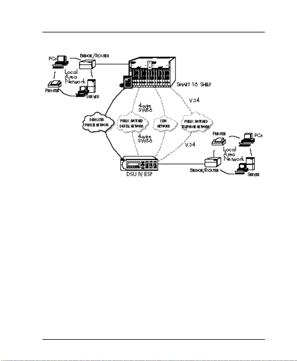
Chapter 1. Introduction
Figure 1-1
Typical Point-to-Point Application for DSU IV ESP
DDS OPERATION
DDS is a nationwide service that allows interconnection and
transport of data at speeds up to 64 kbps. The local exchange
carriers provide the local loop service to DDS customers and
may provide data for routing Inter-LATA to an interexchange
carrier. In DDS mode, the DSU IV ESP supports 2.4 to 64 kbps
DDS service rates yielding DTE rates of 2.4, 4.8, 9.6, 19.2, 38.4
(sync or async), 56 kbps, and 64 kbps. An additional rate of 57.6
is available in asynchronous mode. The unit can be configured
to run slower DTE rates (async or sync) over the 56 or 64 kbps
service.
61204.011L1-1 DSU IV ESP User Manual 3
Page 22

Chapter 1. Introduction
SWITCHED 56 OPERATION
This dial-up, 4-wire Switched 56 DDS allows customers to pay
for data connection only for the time the unit is active. The
regional operating companies provide the 4-wire local loop
service to SW56 customers. The DSU IV ESP supports DTE rates
of 2.4, 4.8, 9.6, 19.2, 38.4, and 56 kbps (synchronous) and 2.4, 4.8,
9.6, 19.2, 38.4, and 57.6 kbps (asynchronous).
SNMP
The term SNMP broadly refers to the message protocols used to
exchange information between the network and the managed
devices, as well as to the structure of network management data
bases. SNMP has three basic components:
Network Manager
Control program that collects, controls, and presents data
pertinent to the operation of the network devices. It resides on a
network management station.
Agent
Control program that resides in each network device connected.
This program responds to queries and commands from the
network manager and returns requested information or invokes
configuration changes initiated by the manager.
MIB
Index to the organized data within a network device. It defines
the operation parameters that can be controlled or monitored.
The DSU IV supports the MIB-II standard, RFC 1213, and
ADTRAN Enterprise Specific MIB. MIB files are available from
ADTRAN in the support section of the ADTRAN Web page at
www.adtran.com.
The DSU IV's embedded SNMP feature allows the unit to be
accessed and controlled by a network manager through either a
device running SLIP or async PPP protocol (connected to the
CONTROL port of the DSU) or through a LAN. LAN connection
4 DSU IV ESP User Manual 61204.011L1-1
Page 23

requires the optional ESP ethernet card (part number
1204005L1). This card provides a 10baseT ethernet interface to
the LAN.
TELNET
TELNET provides a password-protected, remote login facility to
the DSU IV. TELNET allows a user on a network manager to
control the DSU IV through the terminal menus. See the chapter
Applications and the appendix Terminal Menu Structure for more
information.
DIAL BACKUP OPERATION
The DSU IV ESP's unique DBU cards are field-installable by the
customer. See the chapter Installation for information on installing DBU cards. All DBU cards are compatible with other
ADTRAN ESP products supporting DBU (see the following
note). The three backup options are described in the following
sections. Contact the local telco provider to determine which
services are available in your area. See the chapter Applications
for more information, including an example of a dial backup
application.
Chapter 1. Introduction
The ESP V.34 DBU is not compatible with the TSU ESP.
ESP Dial Backup Options
4-Wire Switched 56 Card
This dial-up 4-wire SW56 card allows customers to pay for data
connection only for the time the unit is active. The regional
operating companies provide the 4-wire local loop service to
SW56 customers. This card supports DTE rates of 2.4, 4.8, 9.6,
19.2, 38.4 (asynchronous or synchronous), and 56 kbps (synchro-
nous). An additional DTE rate of 57.6 kbps is available in async
modes.
61204.011L1-1 DSU IV ESP User Manual 5
Page 24

Chapter 1. Introduction
V.34 Card
The V.34 card has all of a V.32 bis modem's modes of operation,
plus V.34 and V.FC modes. This allows the V.34 option to run
synchronous rates up to 33.6 kbps as opposed to the V.32 at 14.4
kbps. In asynchronous mode the throughput at 57.6 kbps is less
dependent on data types.
ISDN Card
1B+D Basic Rate ISDN service provides the customer with a
switched 56/64 kbps circuit. In addition to 56 and 64 kbps
synchronous DTE rates, the card also supports synchronous and
asynchronous DTE rates of 2.4, 4.8, 9.6, 19.2, and 38.4 kbps per
CCITT V.120. The card also supports the DTE rate of 57.6 kbps
async and is compatible with the 4-wire SW56 DBU card.
WARRANTY AND CUSTOMER SERVICE
ADTRAN will replace or repair this product within five years
from the date of shipment if it does not meet its published
specifications or fails while in service. For detailed warranty,
repair and return information refer to the ADTRAN Equipment
Warranty and Repair and Return Policy Procedure.
Return Material Authorization (RMA) is required prior to
returning equipment to ADTRAN.
For service, RMA requests, or further information, contact one of
the numbers listed on the inside back cover of this manual.
6 DSU IV ESP User Manual 61204.011L1-1
Page 25

UNPACK, INSPECT, POWER UP
Receipt Inspection
Carefully inspect the DSU IV ESP for any shipping damage. If
damage is suspected, file a claim immediately with the carrier
and contact ADTRAN Customer Service. If possible, keep the
original shipping container for use in shipping the DSU IV ESP
for repair or for verification of damage during shipment.
Chapter 2. Installation
Chapter 2
Installation
ADTRAN Shipments Include
The following items are included in ADTRAN shipments of the
DSU IV ESP:
• DSU IV ESP unit
• The user manual
• An 8-position modular to 8-position modular cable
• An 8-position modular to 8-position modular cable and a
modular to female DB-25 adapter for access to the Control/
SLIP/PPP port
61204.011L1-1 DSU IV ESP User Manual 7
Page 26

Chapter 2. Installation
Customer Provides
The ADTRAN DSU IV ESP MIB is available from ADTRAN in the
support section of the ADTRAN Web page at www.adtran.com.
The following items are included in ADTRAN shipments of ESP
DBU cards:
• ESP DBU card
• An 8-position modular to 8-position modular cable for the
4-wire SW56 and 1B+D ISDN dial backup options. An
8-position modular to 4-position modular cable for the V.34
backup option.
The customer must provide either a male EIA-232 (standard 25pin, D-type) or a male V.35 interface cable.
For SNMP management, the customer must provide access to
the DSU IV ESP either through a SLIP port, Async PPP port
(requires a male 25-pin D-type connector), or a 10baseT ethernet
port (requires that an ADTRAN ESP Ethernet card be installed in
the DSU IV ESP). See the appendix Pinouts for the pin assignments of the control port (for SLIP and Async PPP) and the
ethernet port.
Power Up
The DSU IV ESP is provided with a captive 8-foot power cord,
terminated by a three-prong plug which connects to a grounded
115 VAC power receptacle.
Power to the DSU must be provided from a grounded 115 VAC, 60 Hz
receptacle.
8 DSU IV ESP User Manual 61204.011L1-1
Page 27
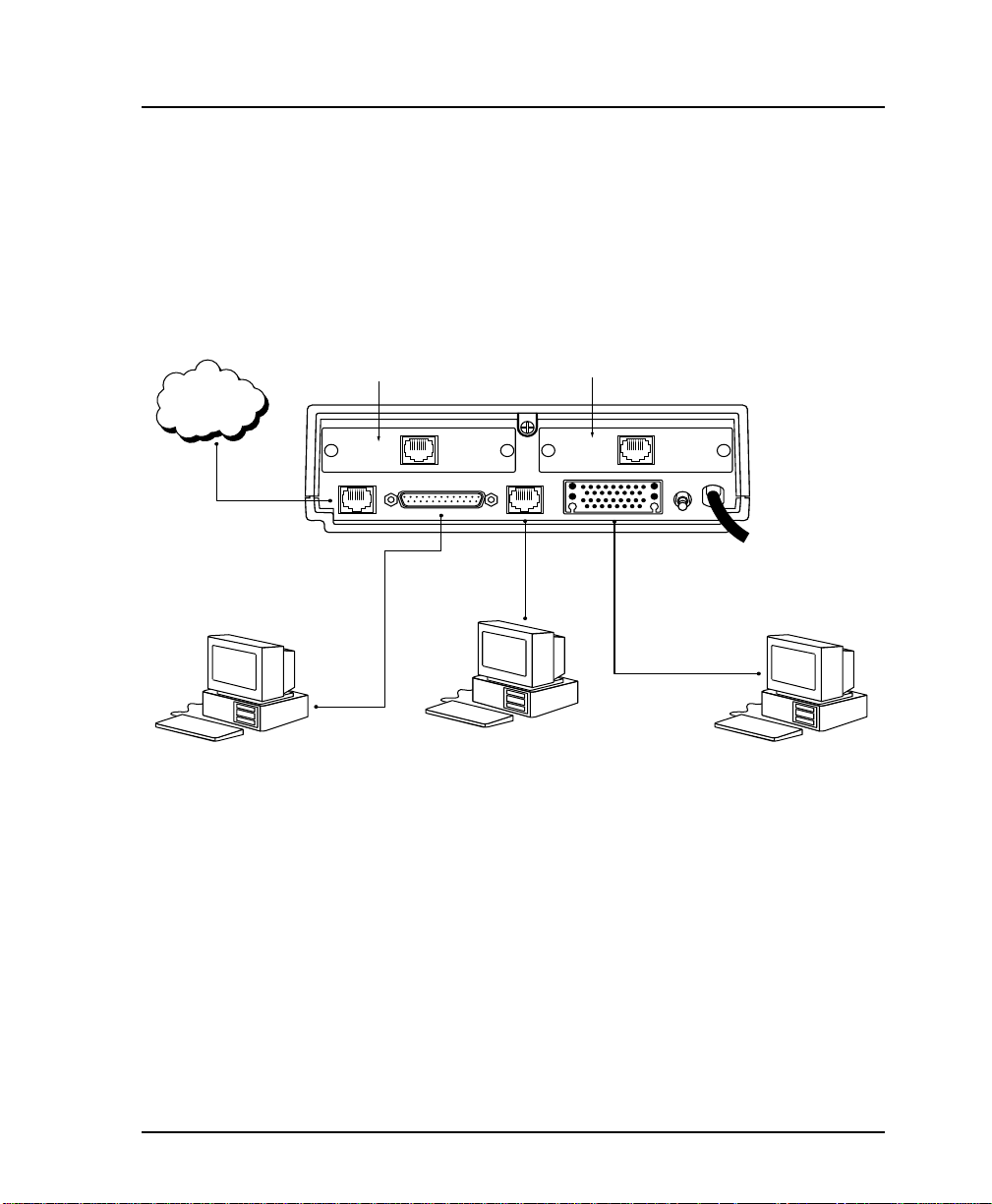
REAR PANEL
Chapter 2. Installation
The rear panel contains two DTE connectors which provide
primary channel V.35 or EIA-232. An 8-pin telco jack, a control
port, a captive power cord, and a power switch are also located
on the rear panel. Pin assignments for these connectors are listed
in the appendix Pinouts. The DSU IV ESP rear panel is shown in
Figure 2-1 with optional ESP cards installed.
DDS
4-wire
S4W, V.34, or
ISDN DBU Card
DBU INTERFACE LAN INTERFACE
ISDN
DBU
TELCO
EIA-232
10BASET LAN Card
CONTROL
V .35
10 BASE T
LAN
115 VAC
60HZ.15A
ON
OFF
Telco Cable
RJ45-to-DB25
EIA232 Cable
Cable
V.35 Cable
VT 100 Terminal or
device running SLIP
DTE Device DTE Device
or async PPP protocol
Item Function
DBU Interface ESP DBU card slot
LAN Interface ESP Ethernet card slot
Telco Connects to dedicated circuit
EIA-232 Connects to a DTE interface
Control Connects to a VT 100 terminal or a
device running SLIP or async PPP
protocol
V.35 High speed DTE interface
Power Switch Turns power on or off
115 VAC Connection Power cord connection
DSU IV ESP Rear View
Figure 2-1
61204.011L1-1 DSU IV ESP User Manual 9
Page 28

Chapter 2. Installation
DBU and Ethernet Card Slots
The DSU IV ESP rear panel has two card slots for the installation
of dial backup and ethernet cards. To insert cards, perform the
following procedure:
1. Remove power from the DSU IV ESP.
2. Slide the card into the corresponding rear slot until the card
panel is flush with the DSU IV chassis.
3. Push card locks in (until they click) to secure the card and
ensure proper installation.
Card slots are keyed to prevent improper installation (i.e., putting a
DBU card into the ethernet slot).
Remove power from the unit prior to installing or removing ESP
option cards.
Telco Connector: Network Interface Connection
The DSU IV ESP has an 8-position modular jack labeled TELCO.
The telco connector is used for connecting to the DDS network.
The pinout for this connector is listed in the appendix Pinouts.
Each ESP DBU card has a connector which is used for connection
to the switched backup network. The pinout for the connector
depends on the card type. Pinouts for 4-wire Switched 56, V.34,
and ISDN 1B+D DBU options are shown in the appendix
Pinouts.
EIA-232 and V.35 Connectors: DTE Data Connection/Primary DTE
The primary DTE should be connected to either the EIA-232 DTE
connector or the V.35 DTE connector. The maximum cable
lengths recommended are 50 feet for the EIA-232, and 100 feet
for the V.35. The pin assignments for the connectors are listed in
the appendix Pinouts.
10 DSU IV ESP User Manual 61204.011L1-1
Page 29

Control Port
Chapter 2. Installation
The V.35 connector is recommended for use with data rates
above 19.2 kbps. The EIA-232 connector works up to 56 kbps
with a low capacitance cable or with the external transmit clock
option selected. The primary DTE rate is configured from the
front panel. The primary DTE equipment can operate in asynchronous or synchronous modes.
To prevent possible radio frequency interference emissions, a shielded
cable is required.
The DSU IV has an 8-position modular jack labeled CONTROL.
The control port provides connection to a VT 100 EIA-232
compatible interface, a device running SLIP protocol, or a device
running Async PPP protocol. An 8-foot adapter connector and
cable provide a standard DB-25 EIA-232 interface. See the
appendix Pinouts for the control port’s pin assignments. A
description of the operation of this port is covered in the Opera-
tion chapter.
The control port also functions as the SLIP or Async PPP port
when configured for SNMP management. The pinouts are
identical when operating in an SNMP management mode.
61204.011L1-1 DSU IV ESP User Manual 11
Page 30

Chapter 2. Installation
12 DSU IV ESP User Manual 61204.011L1-1
Page 31

FRONT PANEL
Chapter 3. Operation
Chapter 3
Operation
The DSU IV ESP faceplate is shown in Figure 3-1. Descriptions
of each part of the front panel follow.
LCD Window
Displays menu items and messages in 2 lines by 16 characters.
Enter
Selects active menu items. To select a menu item, press the
number of the item. The menu item flashes, indicating it is
activated. Press Enter to select the menu item.
Keypad
The keypad contains dual-function keys numbered 0 through 9
with alpha characters A through F. These keys are used to
activate menu items and enter information.
Shift
Enter alpha characters by pressing and releasing Shift before
pressing the key representing the desired character. To activate a
menu item designated by an alpha character rather than a
number press Shift and then the letter. The menu item flashes,
indicating which parameter is activated. Press Enter to select the
item.
If a key is pressed without using Shift, the numbered item
becomes active instead of the alpha item.
61204.011L1-1 DSU IV ESP User Manual 13
Page 32

Chapter 3. Operation
Cancel
Pressing the Cancel key stops the current activity and returns to
the previous menu. Repeat until the desired menu level is
reached. When a submenu item is displayed, press Cancel to
exit the current display and return to the previous menu.
Up and Down Arrows
Up and Down Arrows scroll through the submenu items available in the current menu.
LED Descriptions
The DSU IV ESP has seven LED indicators: RS, CS, TD, RD, CD,
ALM, and TST. These LEDs are identified as follows:
RS: Request to Send Reflects the status of the request to send
pin of the DTE interface.
CS: Clear to Send Reflects the status of the clear to send
pin of the DTE interface.
TD: Transmit Data This LED is active when data is trans-
mitted from the DTE.
RD: Receive Data This LED is active when data is received
from the network.
CD: Carrier Detect This LED is active when frame synchro-
nization is achieved and the DSU IV ESP
is ready to transfer data.
ALM: Alarm Indication
This LED activates whenever an alarm
condition exists. Alarm conditions
include:
• Open loop on network
• No frame synchronization
• Unit in dial backup
• Problem on dial backup line
TST: Test Mode This LED is on whenever the unit is in
test mode.
14 DSU IV ESP User Manual 61204.011L1-1
Page 33

Chapter 3. Operation
CS LED
Reflects status of
CTS pin of the
primary DTE
connector.
RS LED
Reflects status of
RTS pin of the
primary DTE
connector.
TD LED
Active when DTE
port transmits
data.
LCD Window
Displays menu items and
messages in 2 lines by 16
RD LED
Active when DTE port
receives data.
alarm condition
characters.
CD LED
Active when DSU receives a
carrier signal from the line.
Up and Down Arrows
Scroll through the
submenu items available
in the current menu.
ALM LED
Active when
exists.
TST LED
Active when the unit is in
test mode.
Selects active menu item.
ENTER
CANCEL
Cancel
Stops current
activity and
returns to the
previous menu.
Enter Key
A
1
D
4
7
SHIFT
*
Keypad
Activates menu items and
enters numeric information.
DSU IV ESP
B
2
E
5
8
0
C
3
F
6
9
QUICK
#
Shift
Activates alpha selections.
Quick Key
Returns display to
Main menu, Exit
Test screen, or DBU
options menu.
Figure 3-1
DSU IV ESP Front Panel
61204.011L1-1 DSU IV ESP User Manual 15
Page 34

Chapter 3. Operation
16 DSU IV ESP User Manual 61204.011L1-1
Page 35

Front Panel Menu Navigation
To choose a menu item, press the corresponding number or
alpha character on the keypad. Press Shift to activate menu
items with alpha selections. The flashing menu item indicates
which selection is activated. Press Enter to select the item. The
following steps and Figure 3-2 illustrate how to select DSU IV
ESP options:
1. Activate Configuration (CONFIG) by pressing 3. The
activated menu item will flash. Press Enter.
2. Select LOCAL or REMOTE configuration by pressing the
corresponding number, then press Enter.
3. Use the arrow keys to view submenu items.
4. Choose an item on the submenu such as Network Options
(NETWORK OPT).
5. Activate NETWORK OPT by pressing 1. Press Enter.
6. Activate LOOP RATE options by pressing 1. Press Enter.
7. Press the number corresponding to the desired loop rate.
Press Enter.
Chapter 3. Operation
1=LOOP RATE
1=LOCAL 1=NETWORK OPT. 2=NETWORK ADDR.
3=CONFIG 2=DTE OPTIONS 3=REMOTE CONFIG
2=REMOTE 3=TEST OPTIONS 4=NETWORK TYPE
4=DIAL OPTIONS 5=CLOCK SOURCE
5=MANAGEMENT
6=UTILITIES
Figure 3-2
Example of Basic Menu Navigation
61204.011L1-1 DSU IV ESP User Manual 17
Page 36

Chapter 3. Operation
Front Panel Menu Structure
The DSU IV ESP uses a multilevel menu approach to access its
many features. All menu operations are displayed in the LCD
window or the terminal. See Figure 3-3 for the terminal Main
menu.
The opening menu is the access point to all other operations.
Each Main menu item has several functions and submenus to
identify and access specific parameters.
Front panel LCD display of the Main menu:
The Dial selection in the Main menu is only available when a SW56
network type is selected or when a DBU card is installed in the rear of
the DSU IV ESP.
Main Menu
1=STATUS 2=TEST
3=CONFIG 4=DIAL
The branches of the front panel Main menu are divided into
options for Status, Test, Configuration (CONFIG), and Dial.
Status
Status menus display all relevant information for the network
and DTE interfaces. The system returns to the status display
when idle. For more information see the chapter Viewing Status
Information.
Test
Use Test menus to control local and remote testing. Select local
or remote testing, and the type of test and test pattern when
required. For more information, see the chapter Testing and
Troubleshooting.
18 DSU IV ESP User Manual 61204.011L1-1
Page 37

Chapter 3. Operation
Configuration
Use Configuration menus to select network and DTE operating
parameters, configure testing and dialing options, select management functions, and configure unit utilities. This menu
branch is divided into several chapters for easier reference. The
division includes a brief overview chapter followed by a separate chapter for each of the six submenus: Configuring Network
Options, Configuring DTE Options, Configuring Test Options,
Configuring Dial Options, Configuring Management Functions, and
Configuring Unit Utilities.
Dial
Dial provides manual dial backup or SW56 dial functions. For
more information, see the chapter Activating Dialing Functions.
61204.011L1-1 DSU IV ESP User Manual 19
Page 38

Chapter 3. Operation
VT 100 TERMINAL CONNECTION AND OPERATION
To control the DSU IV ESP using a VT 100 terminal, perform the
following procedure:
1. Select a terminal interface through the front panel. Select 3
CONFIG, 5 MANAGEMENT, 1 INTERFACE, 1 TERM
CONTROL.
2. Set the CONTROL RATE to match the VT 100 terminal.
3. Using the provided VT 100 terminal adapter cable, connect
the COM port of a VT 100 compatible terminal or equivalent
to the eight-pin modular jack labeled CONTROL on the rear
of the DSU IV ESP. This connection is used for both local
and remote configuration.
4. Establish the connection and press Enter repeatedly until the
Terminal Menu appears (Figure 3-3).
5. Make selections by entering the number corresponding to
the chosen parameter. Press ESC to return to the previous
screen.
Due to the increased display capabilities, the VT 100 menu structure
differs from the front panel interface. The appendix Terminal Menu
Structure includes the VT 100 screens as well as a complete menu tree
for accessing configuration selections. Descriptions of individual menu
options are provided throughout this manual based on the front panel
menu structure. See Figure 5-1 for the front panel configuration menu
tree.
When establishing a TELNET session, the system prompts for a
password. The default password is adtran. This password can be
modified through the Management menu. See the chapter Configuring
Management Functions for more information.
20 DSU IV ESP User Manual 61204.011L1-1
Page 39

Chapter 3. Operation
Figure 3-3
Terminal Interface Main Menu (SW56 Mode)
61204.011L1-1 DSU IV ESP User Manual 21
Page 40

Chapter 3. Operation
22 DSU IV ESP User Manual 61204.011L1-1
Page 41

Chapter 4. Applications
Chapter 4
Applications
This chapter provides examples of some common DSU IV ESP
applications. The examples include LAN applications with both
SLIP/PPP and ethernet management and a dial backup application.
LAN APPLICATION WITH SNMP/TELNET MANAGEMENT
The DSU IV can be managed through an established TELNET
session or an SNMP-based network manager like HP
Openview®, IBM Netview®, or SunNet Manager®.
The ADTRAN DSU IV ESP MIB is available in the support section of
the ADTRAN Web page at www.adtran.com.
SNMP and TELNET management are provided by one of the
following interfaces:
• A device (i.e., a router) running SLIP protocol. Connection is
made through the DSU IV's control port. See Figure 4-1.
• A device (i.e., a router) running async PPP protocol. Connec-
tion is made through the DSU IV's control port. See Figure 4-1.
• A LAN. Connection is made through the optional 10baseT
ethernet interface provided on the ESP ethernet card (part
number 1204005L1). See Figure 4-2.
61204.011L1-1 DSU IV ESP User Manual 23
Page 42

Chapter 4. Applications
LAN
LAN
Router
Router
SNMP
Managment Station
SLIP/PPP
EIA 232 or V.35
DSU IV ESP
A
B
1
C
2
D
3
E
4
TD1
RD1
TD2
RD2
TDNRDN
F
5
ALM
NEXT
/TST
6
PREV
7
ADD
8
SHIFT
9
DELETE
QUICK
0
#
SLIP/PPP LAN Application with SNMP/TELNET Management
SNMP
Management Station
Ethernet
EIA 232 or V.35
DSU IV ESP
A
B
1
C
2
D
3
E
4
TD1
RD1
TD2
RD2
F
5
ALM
TDNRDN
NEXT
/TST
6
PREV
7
ADD
8
SHIFT
9
DELETE
QUICK
0
#
DSU IV ESP
DSU IV ESP
Frame Relay
DDS or
Frame Relay
DDS or
TD1
RD1
TD2
TD1
RD1
TD2
RD2
ALM
TDNRDN
/TST
SLIP/PPP
EIA 232 or V.35
A
1
D
4
RD2
ALM
TDNRDN
NEXT
/TST
7
SHIFT
DELETE
Ethernet
EIA 232 or V.35
DSU IV ESP
A
B
1
2
D
E
4
5
NEXT
PREV
7
ADD
8
SHIFT
DELETE
QUICK
0
#
DSU IV ESP
B
C
2
3
E
F
5
6
PREV
ADD
8
9
QUICK
0
#
DSU IV ESP
C
3
F
6
9
DSU IV ESP
LAN
Router
Figure 4-1
LAN
Router
Figure 4-2
Ethernet LAN Application with SNMP/TELNET Management
24 DSU IV ESP User Manual 61204.011L1-1
Page 43

Chapter 4. Applications
Minimum Configuration Requirements for SNMP/TELNET Access
The following options are the minimum configuration requirements for establishing SNMP or TELNET access. Once these
options are configured, the remaining options may be configured
using SNMP/TELNET. See the menu tree in Figure 10-1 in the
chapter Configuring Management Functions for the front panel
menu path to these options.
Interface
Select SLIP Control, PPP Control, or Ethernet LAN as the DSU IV
interface type. The ESP ethernet card must be installed for the
Ethernet LAN selection.
IP Address
Enter the DSU IV ESP IP address.
Subnet Mask
Enter the subnet number. This address is available from the
network administrator.
Gateway IP Address (if required)
Enter the Gateway node IP address. This address is necessary
only if the DSU IV and the network manager are connected
through a Gateway node. This address is available from the
network administrator.
Special Features of this Application
Customize the SNMP/TELNET application using the following
DSU IV ESP features:
• Designate SNMP hosts to receive SNMP traps from the DSU IV
(one to five entries).
• Secure the DSU IV by limiting SNMP network management
access. If enabled, the DSU IV only responds to a user-configured list of SNMP network managers (one to five entries).
Configure these options through the Management portion of the
Configuration menu. See the chapter Configuring Management
Functions for more information.
61204.011L1-1 DSU IV ESP User Manual 25
Page 44

Chapter 4. Applications
DIAL BACKUP APPLICATION
The DSU IV provides point-to-point connection to the network.
With one of the ESP DBU option cards installed, the unit is
capable of dial backup, allowing the unit to dial around a failed
network. See Figure 4-3.
With the DBU options, configure the unit to:
• Enter DBU under specific primary network conditions.
• Lock out DBU over the weekend and/or at specified times of
the day.
• Dial a specified number when a DBU activation condition is
detected.
DTE Device
DSU IV ESP
A
B
1
C
2
D
3
E
4
TD1
RD1
TD2
RD2
F
5
ALM
TDNRDN
NEXT
/TST
6
PREV
7
ADD
8
SHIFT
9
DELETE
QUICK
0
#
DSU IV ESP
V .34, ISDN,
4-Wire
Switched 56
Switched
Network
DDS
DTE Device
TD2
RD2
TDNRDN
F
5
ALM
NEXT
/TST
6
PREV
7
ADD
8
SHIFT
9
DELETE
QUICK
0
#
DSU IV ESP
A
B
1
C
2
D
3
E
4
TD1
RD1
DSU IV ESP
Figure 4-3
Dial Backup Application
Entering Dial Backup Mode
When a condition for entering dial backup mode is detected, the
Alarm LED turns on and the buzzer sounds. The buzzer alternates between 30 seconds on and 30 seconds off unless the DDS
line is restored or it is disabled by using the Quick key and
selecting Turn Off Beep. See the section Front Panel in the
chapter Operation for more information on the Quick key.
26 DSU IV ESP User Manual 61204.011L1-1
Page 45

Operation During Critical Times
The following four conditions will cause a DSU IV ESP to enter
dial backup mode:
Loss of Sealing Current
Sealing current is a low voltage DC current provided by the
central office (CO) to prevent corrosion over the copper wires
used in the local loop. Sealing current may also be used for local
loop testing purposes. An absence of sealing current generally is
an indication that the loop is open.
Out of Service (OOS) Signal
An OOS signal, generated by the network, indicates a device (or
devices) in the network is out of service.
No Receive Signal
This is an indication that the local loop copper pairs may be
either open or shorted or the OCU in the CO is inoperative. In a
private network this may indicate that the transmitter of the
remote DSU is inoperative.
All 1s or all 0s Condition
This condition is usually generated by the network to indicate
some device (or devices) in the network is inoperative. Upon
detecting an all 1s or all 0s condition, the DSU IV ESP initiates a
handshake routine to determine whether the remote unit's DTE
is the source of the all 1s or 0s condition or if an actual network
failure exists.
Chapter 4. Applications
Answer Always
When this option is enabled, the unit goes into DBU mode if a
call is present regardless of the status of the dedicated circuit. It
is recommended that the DBU Passcode be used in this mode
since inadvertent calls could stop data flow indefinitely.
The DBU Answer Test is disabled if this option is chosen.
61204.011L1-1 DSU IV ESP User Manual 27
Page 46

Chapter 4. Applications
Operation During Noncritical Times
The DSU IV ESP may be configured not to enter dial backup
mode if data terminal ready (DTR) is low. This feature prevents
the DSU IV ESP from entering dial backup during noncritical
times such as nights and weekends.
For more information, see the chapter Configuring Dial Options.
Weekend and Time of Day Lockout
The DSU IV ESP may be configured not to enter dial backup
mode based upon the time of day or weekend status. This
protects the customer from being charged for a switched call
during off hours should the dedicated circuit fail. See the
chapter Configuring Dial Options for more information.
Conditions for Returning to the DDS Circuit
The DSU IV ESP can be configured to automatically revert to the
DDS circuit from the dial backup mode or wait to be returned to
the DDS manually. Once the DSU IV ESP enters dial backup
mode, the unit polls the DDS circuit once every 100 ms to
determine if the condition causing the DDS circuit failure has
been corrected. Once the DSU IV ESP determines that the
problem has been properly corrected and the DDS circuit is
stable, it will wait for the amount of time specified in the restore
timer (1 - 255 minutes) before reverting to the DDS circuit.
Polling of the DDS circuit is non-intrusive and return to the DDS
circuit generally takes 2 - 3 seconds. The backup connection is
maintained for one minute after the DDS circuit is restored.
See the chapter Configuring Dial Options for more detailed
information.
28 DSU IV ESP User Manual 61204.011L1-1
Page 47

Chapter 5. Configuration Overview
Chapter 5
Configuration Overview
The DSU IV ESP contains four different user profiles (sets of
configuration options) stored in read only memory; see the
appendix Configuration Profiles. The unit is shipped from the
factory with profile number 1 (default configuration) loaded into
the current (nonvolatile configuration) memory. If profile 1
matches requirements for the system, then no additional configuration is required to put the unit into service. If profile 1
does not match system requirements, it can be modified or one
of the other profiles that more closely matches the system
requirements can be loaded into current memory. When a
different profile is loaded or the existing profile is modified, it is
stored in the current (nonvolatile configuration) memory. The
DSU IV ESP is then configured with that profile every time
power is turned on or the unit is reset.
CONFIGURATION METHODS
The DSU IV ESP responds to the following methods of configuration:
• AT commands
• V.25 commands
• Front panel commands
• A VT 100 compatible terminal
• SNMP/TELNET through a device running SLIP/PPP protocol
• SNMP/TELNET through a LAN running ethernet protocol
(available when the optional ESP Ethernet card is installed)
61204.011L1-1 DSU IV ESP User Manual 29
Page 48

Chapter 5. Configuration Overview
AT and V.25 commands have limited access to configuration
parameters. The commands are detailed in the following
sections of this chapter. See the chapters Installation and Opera-
tion for more information on all other configuration methods.
For an example application using the SLIP/PPP or ethernet
interface, see the chapter Applications.
Descriptions of each Configuration menu item are given in the
following chapters: Configuring Network Options, Configuring
DTE Options, Configuring Test Options, Configuring Dial Options,
Configuring Management Functions, and Configuring Unit Utilities.
A complete Configuration menu for the front panel is shown in
Figure 5-1. The VT 100 menu tree is shown in the appendix
Terminal Menu Structure.
Due to the increased display capabilities, the VT 100 menu structure
differs from the front panel interface. The appendix Terminal Menu
Structure includes the VT 100 screens as well as a complete menu tree
for accessing configuration selections. Descriptions of individual menu
options are provided throughout this manual based on the front panel
menu structure. See Figure 5-1 for the front panel configuration menu
tree.
30 DSU IV ESP User Manual 61204.011L1-1
Page 49

Chapter 5. Configuration Overview
Configuring DTE Options
p
Configuring Dial Options
1=2.4K
1=LOOP RATE 2=2.4K 4=19.2K
1=NETWORK OPT. 4=9.6K 1=DTE RATE 6=56K/57.6K 1=SCRAMBLER OFF
2=NETWORK ADDR. ENTER NETWORK 2=SYNCHRONOUS 2=ASYNC 10 BITS
3=REMOTE CONFIG. 1=DISABLED 4=DTE CMD OPTION 2=AT COMMAND SET
4=NETWORK TYPE 1=DEDICATED
5=CLOCK SOURCE 1=MASTER
2=DTE OPTIONS 2=TIME 10 SEC. 5=OFF WITH LOCD 2=CS DELAY LONG
1=TEST TIMEOUT (0=OFF) : 00 SEC 8=CD OPTIONS 2=NORMAL
1=LOCAL 2=RDL ACCEPTED 9=TR OPTIONS These selections are dependent upon the operation mode (SW56 or DBU). See the chapter
3=CONFIG 3=TEST OPTIONS 2=ENABLED A=SR OPTIONS 1=FORCED ON
2=REMOTE ENTER ADDRESS 4=EIA RLB EN/DIS 1=DISABLED 3=OFF LOCD ONLY
4=DIAL OPTIONS 2=SW56 AUTO ANS 1=DISABLED
5=MANAGEMENT 3=PPP CONTROL
6=UTILITIES 1=MANUAL COMMAND COMMAND: 00 COMMAND: HH 2=ENABLE
2=RDL EN/DIS 1=RDL IGNORED
3=EIA LLB EN/DIS 1=DISABLED
5=DBU ANS. TEST 1=DISABLED 6=OFF TEST + LOCD STORED NUMBER TO
2=TIME/DATE 1=CURRENT TIME=23:01:59 2=CONTROL RATE 3=9600 BPS
3=SOFTWARE REV. REV X XXXX 3=60 MINUTES
4=LAN MAC ADDR.
5=SERIAL NUMBER xxxxxxxxxxxxxxx
1=AUTO 3=9.6K
3=4.8K 5=38.4K
5=19.2K 7=SAME AS LOOP 2=SCRAMBLER ON
6=38.4K 3=SUPPRESS LBE
7=56K 1=EIA 232
8=64K 2=CONNECTOR TYPE 2=V.35
3=DATA FORMAT 1=ASYNCHRONOUS 1=ASYNC 9 BITS
ADDRESS:00 3=ASYNC 11 BITS
2=ENABLED 3=V.25 SYNC
2=AT&T/MCI SW56 5=TRANSMIT CLOCK 1=NORMAL
3=US SPRINT SW56 2=EXTERNAL 1=FORCED ON
6=CS OPTIONS 3=FOLLOWS CD 2=CS DELAY LONG
2=FROM NETWORK 7=ANTI-STREAM 1=TIMER OFF 4=FOLLOWS RS+CD 1=CS DELAY SHORT
ENTER TIMEOUT 4=TIME 60 SEC. 1=FORCED ON
2=OFF OOS ONLY
2=ENABLED 4=OFF TEST ONLY
2=ENABLED 1=PHONE NUMBERS EDIT (1-10): NNNNNNN
VALUE:00 1=1200 BPS
DATE=08/15/97
2=SET TIME 1=SET HOURS ENTER CURRENT 3=IP OPTIONS 2=SUBNET MASK
2=SET MINUTES ENTER CURRENT
3=SET SECONDS ENTER CURRENT 4=SNMP OPTIONS 3=TRAP COMMUNITY 1=DISABLE
3=SET DATE 1=SET MONTH ENTER CURRENT 5=TRAP IP ADR ENTER TRAP IP
2=SET DAY ENTER CURRENT 8=SYS LOCATION 1=DISABLED
3=SET YEAR ENTER CURRENT 1=TELN PASSWORD
VERSION CHKSUM 2=TELNET TIMEOUT 2=30 MINUTES
HOUR (HH):01 3=GATEWAY IP ADR 1=DISABLED
MIN. (MM):01 1=GET COMMUNITY 5=IP FILTER ADDR ENTER SOURCE IP
SEC. (SS):01 4=SNMP TRAPS 2=GENERIC ONLY
MONTH (MM):01 6=SYS NAME NUMBER (1-5):1
DAY (DD):07 9=AUTHEN TRAP 2=ENABLED
YEAR (YY):97 5=TELNET OPTIONS 1=10 MINUTES
5=OFF TEST + OOS
1=INTERFACE 1=VT100 CONTROL 3=DBU OPTIONS These selections are dependent upon the DBU card.
2=4.8K
1=DISABLED
4=V.25 BSC/ASYNC
3=INVERT 2=FOLLOWS RS 1=CS DELAY SHORT
3=TIME 30 SEC.
3=OFF WITH LOCD
for more information.
2=SLIP CONTROL See the cha
4=ETHERNET LAN 4=DBU PASSCODE 1=ENABLE/DISABLE 1=DISABLE
2=2400 BPS 2=ENTER CODE XXXX
1=UNIT IP ADR
4=IP SECURITY 2=ENABLED
2=SET COMMUNITY NUMBER (1-5):1
3=ENABLE ALL
7=SYS CONTACT
2=ENABLED
ter
for this portion of the menu tree.
Figure 5-1
Front Panel Configuration Menu Tree
61204.011L1-1 DSU IV ESP User Manual 31
Page 50

Chapter 5. Configuration Overview
32 DSU IV ESP User Manual 61204.011L1-1
Page 51

AT Commands
Chapter 5. Configuration Overview
The DSU IV ESP can be configured and controlled with in-band
AT commands from an asynchronous DTE port just as modems
are.
To exit the data mode and enter the command mode, the asynchronous DTE device must transmit a proper escape sequence of
three pluses (+++) to the DSU IV ESP. A specified time delay
must occur between the last data character and the first escape
sequence character. This is the guard time delay, and it can be
changed by writing a value to the S12 register. The default value
for the guard time is one second. For a valid escape sequence to
occur, the DTE must transmit the escape code character three
times in succession with delay between each character being less
than the guard time.
Once the command mode is entered, AT commands can be
transmitted to the DSU IV ESP to configure most of the options
or initiate tests to check both the DSU IV ESP and the network
connections. All command lines must begin with the AT character set in either capital or lower case letters.
The command line may contain a single command or a series of
commands after the AT attention code. When a series of commands is used, the individual commands may be separated with
spaces for readability. The maximum length for a command line
is 40 characters. Each command line is executed by the DSU IV
ESP upon receipt of a terminating character. The default terminating character is a carriage return (ASCII 013), but it can be
changed by writing a different value to register S3.
Before the terminating character is transmitted, the command
line can be edited by using the backspace character (ASCII 008)
to erase errors so the proper commands can be entered.
Not all parameters can be selected using these commands. Valid
commands are listed in the appendix AT Commands.
61204.011L1-1 DSU IV ESP User Manual 33
Page 52

Chapter 5. Configuration Overview
V.25 bis Commands
When configured for the V.25 bis option, the DSU IV ESP accepts
in-band dialing and configuration commands from both synchronous and asynchronous DTE ports.
The V.25 bis option supports the following protocols:
• SDLC
• Bi-Sync
• Asynchronous
SDLC Option
Character Format
• Data bits - 8
• Parity bit - Ignored
Command Structure
[F][A][C][V.25 bis COMMAND][FCS][F]
The address field [A] is FFH. The control field [C] is set to 13H
except for cases of multi-frame responses. For this case, the
control field is set to 03H in all but the last frame. The 03H in the
control field indicates that other frames are to follow while the
13H in the control field indicates the final frame.
Bi-Sync Option
Character Format
• Data bits - 7
• Parity bit - Odd
Command Structure
[SYN][SYN][STX][V.25 bis COMMAND][ETX]
34 DSU IV ESP User Manual 61204.011L1-1
Page 53

Asynchronous Option
Character Format
• Start bit - 1
• Data bits - 7
• Parity bit - Even
• Stop bit - 1
Command Structure
[V.25 bis COMMAND][CR][LF]
Command Descriptions
The ADTRAN V.25 bis command set is a subset of the CCITT
V.25 bis command set. In addition to the CCITT commands
supported, ADTRAN has added configuration commands for
both local and remote DSUs. The ADTRAN V.25 bis command
set follows:
CNL Configuration local
CNR Configuration remote
Chapter 5. Configuration Overview
Possible responses to V.25 bis commands follows:
VALA Valid V.25 command processed
INV An invalid command detected
INVCU Unknown command detected
INVPS Invalid parameter syntax
INVPV Invalid parameter value
INVBL Invalid local password
INVBM Invalid remote password
If verbose responses are disabled (ATV0), the following threecharacter responses are the only ones returned:
VAL Valid V.25 command processed
INV Invalid command received
61204.011L1-1 DSU IV ESP User Manual 35
Page 54

Chapter 5. Configuration Overview
Syntax and Possible Responses
CNL (Configuration Local)
This command is used to pass AT commands to the local DSU
via the V.25 bis command processor. This allows the DSU IV ESP
to be configured with AT commands using a synchronous
interface. The format is as follows:
CNL[LOCAL PASSWORD];AT[ONE OR MORE AT COMMANDS]
A local password may not be required depending on the present
configuration of the unit. Responses to CNL commands are
returned in the data format currently configured. Possible
responses include: VALA and INVAn.
CNR (Configuration Remote)
This command is used to pass AT commands over the network
to the remote DSU via the V.25 bis command processor. This
allows a remote DSU IV ESP to be configured from a synchronous interface. The format of this command follows:
CNR[REMOTE PASSWORD];AT[ONE OR MORE AT COMMANDS]
The remote password may or may not be required depending on
the present configuration of the remote unit. Responses to the
CNR commands are returned in the data format currently
configured. Possible responses include: VAL and INVAn.
36 DSU IV ESP User Manual 61204.011L1-1
Page 55

NETWORK OPTIONS
The Network Options configuration parameters control the loop
operation of the DSU IV ESP. Once a parameter is set, Com-
mand Accepted is displayed briefly before returning to the
active menu. Table 6-A shows the AT commands used to set the
Network Options. See Figure 6-1 for the Network Options menu
tree.
Chapter 6. Configuring Network Options
Chapter 6
Configuring Network Options
61204.011L1-1 DSU IV ESP User Manual 37
Page 56

Chapter 6. Configuring Network Options
p
Front Panel AT Command
Rate
Loo
AUTO %B0
2.4K %B1
4.8K %B2
9.6K %B3
19.2K %B4
38.4K %B5
56K %B6
64K %B7
Network Address
XX (decimal) _N=xx
Remote Configuration
1=DISABLED &P4
2=ENABLED &P5
Network Type
1=DEDICATED
2=AT&T/MCI SW56 none
3=US SPRINT SW56 none
Clock Source
1=MASTER _X0
2=FROM NETWORK _X1
Table 6-A
Network Options AT Commands
none
38 DSU IV ESP User Manual 61204.011L1-1
Page 57

Chapter 6. Configuring Network Options
1=LOOP RATE 2=2.4K
1=AUTO
3=4.8K
1=NETWORK OPT. 4=9.6K
1=LOCAL 5=19.2K
2=DTE OPTIONS 6=38.4K
3=CONFIG 3=TEST OPTIONS 7=56K
2=REMOTE ENTER ADDRESS 4=DIAL OPTIONS 8=64K
5=MANAGEMENT
6=UTILITIES
2=NETWORK ADDR. ENTER NETWORK
ADDRESS:00
3=REMOTE CONFIG. 1=DISABLED
2=ENABLED
4=NETWORK TYPE 1=DEDICATED
2=AT&T/MCI SW56
3=US SPRINT SW56
5=CLOCK SOURCE 1=MASTER
2=FROM NETWORK
Network Options Menu Tree
Loop Rate
The Loop Rate option sets the loop operating speed. The unit
should be set to the rate required by the DDS Service. The DSU
IV ESP also supports subrate DTE data over a 56 or 64 kbps loop.
The loop rate must be set independently of the DTE rate. Eight
loop rate selections are available (shown in Figure 6-1).
Figure 6-1
The default factory setting is Auto. The various loop rates and
format selections are listed in Table 6-A with the equivalent AT
commands that perform the same configuration functions.
61204.011L1-1 DSU IV ESP User Manual 39
Page 58

Chapter 6. Configuring Network Options
Network Address
A two-digit decimal address can be assigned to each DSU IV
ESP. This addressing capability makes it possible to perform
remote configuration and testing in point-to-point and multidrop networks. Figure 6-1 shows the menu path used to change
the network address. The factory default setting is 0.
Remote Configuration
This option sets up the DSU IV ESP to accept or reject remote
configuration commands. The factory default setting is
Enabled.
Network Type
Select the appropriate network type. The choices are dedicated,
AT&T/MCI SW56, and US Sprint SW56.
Clock Source
The Clock Source option specifies the timing source for the DSU
IV ESP’s internal circuitry. The factory default setting is From
Network.
When operating on a DDS network, the timing should be From
Network. On a point-to-point private network, one DSU IV ESP
must be set for Master, the other set for From Network.
40 DSU IV ESP User Manual 61204.011L1-1
Page 59

DTE OPTIONS
Chapter 7. Configuring DTE Options
Chapter 7
Configuring DTE Options
The DTE Options menu is used to select the configuration
parameters that control the operation of the DTE Interface of the
DSU IV ESP. The DTE Options menu tree is shown in Figure 7-1.
Table 7-A shows the available options and their AT commands.
61204.011L1-1 DSU IV ESP User Manual 41
Page 60

Chapter 7. Configuring DTE Options
1=2.4K
2=4.8K
3=9.6K
4=19.2K
1=DTE RATE 6=56K/57.6K
1=NETWORK OPT. 2=SCRAMBLER ON
2=DTE OPTIONS 2=CONNECTOR TYPE 1=EIA 232 3=SUPPRESS LBE
1=LOCAL 4=DIAL OPTIONS
3=CONFIG 6=UTILITIES 2=SYNCHRONOUS 2=ASYNC 10 BITS
2=REMOTE ENTER ADDRESS 3=ASYNC 11 BITS
3=TEST OPTIONS 2=V.35
5=MANAGEMENT 3=DATA FORMAT 1=ASYNCHRONOUS 1=ASYNC 9 BITS
4=DTE CMD OPTION 1=DISABLED
5=TRANSMIT CLOCK 2=EXTERNAL
6=CS OPTIONS 1=FORCED ON
7=ANTI-STREAM 1=TIMER OFF
8=CD OPTIONS 3=OFF WITH LOCD
9=TR OPTIONS 1=IGNORED
A=SR OPTIONS 4=OFF TEST ONLY
5=38.4K
7=SAME AS LOOP 1=SCRAMBLER OFF
2=AT COMMAND SET
3=V.25 SYNC
4=V.25 BSC/ASYNC 1=NORMAL
3=INVERT
2=FOLLOWS RS 1=CS DELAY SHORT
3=FOLLOWS CD 2=CS DELAY LONG
4=FOLLOWS RS+CD 1=CS DELAY SHORT
5=OFF WITH LOCD 2=CS DELAY LONG
2=TIME 10 SEC.
3=TIME 30 SEC. 1=FORCED ON
4=TIME 60 SEC. 2=NORMAL
2=IDLE WHEN OFF
3=OFF>ON DIAL #1
4=OFF>ON DIAL #2 1=FORCED ON
5=NO DBU IF OFF 2=OFF OOS ONLY
3=OFF LOCD ONLY
5=OFF TEST + OOS
6=OFF TEST + LOCD
Figure 7-1
DTE Options Menu Tree
42 DSU IV ESP User Manual 61204.011L1-1
Page 61

Chapter 7. Configuring DTE Options
p
y)
p
y)
Table 7-A
DTE Options AT Commands
Front
Panel
AT
Command
Description
DTE Rate
1=2.4K %K3 DTE rate: 2.4K sync and async
2=4.8K %K4 DTE rate: 4.8K sync and async
3=9.6K %K5 DTE rate: 9.6K sync and async
4=19.2K %K6 DTE rate: 19.2K sync and async
5=38.4K %K7 DTE rate: 38.4K sync and async
6=56K/57.6K %K8
DTE rate: 56K sync or 57.6K async
7=SAME AS LOOP %K9 DTE rate matches loop rate
1=SCRAMBLER OFF
2=SCRAMBLER ON
_F0
_F1
DTE data scrambler disabled (64 kbps
loo
rate onl
DTE data scrambler enabled (64 kbps
loo
rate onl
3=SUPPRESS LBE _F2 Suppresses loopback enable code
(LBE) in transmit data from the DTE
after 30 bytes in a row detected (64
kbps loop rate only)
Data Format
1=ASYNCHRONOUS &Q0 Asynchronous DTE operation mode
2=SYNCHRONOUS &Q2 Synchronous DTE operation mode
DTE CMD Option
1=DISABLED none Disables all DTE command modes
2=AT COMMAND SET none Enables AT command mode for DTE
3=V.25 SYNC none Enables V.25 (SDLC) command mode
for DTE
4=V.25 BSC/ASYNC none Enables V.25 (bisync or async)
command mode for DTE
Transmit Clock
1=NORMAL &X0 TX clock from DSU selected
2=EXTERNAL &X1 ETC clock from DTE selected
3=INVERT &X3 Inverted Tx clock from DSU selected
61204.011L1-1 DSU IV ESP User Manual 43
Page 62

Chapter 7. Configuring DTE Options
Table 7-A (Continued)
DTE Options AT Commands
Front
Panel
CS Options
1=FORCED ON &R 0 CS always on
2=FOLLOWS RS &R1 CS state same as RS state
3=FOLLOWS CD &R2 CS state same as CD state
4=FOLLOWS RS+CD &R3 CS state same as RS and CD state
5=OFF WITH LOCD &R4 Off 5 sec after LOCD (SW56 only)
For Follows RS options, select the length of the delay.
1=CS DELAY SHORT _D0 Short delay from RS to CS selected
2=CS DELAY LONG _D1 Long delay from RS to CS selected
Anti-Stream
1=TIMER OFF %T0 Anti-stream timer disabled
2=TIME 10 SEC. %T1 Timeout equals 10 seconds
3=TIME 30 SEC. %T2 Timeout equals 30 seconds
4=TIME 60 SEC. %T3 Timeout equals 60 seconds
CD Options
1=FORCED ON &C0 On all the time
2=NORMAL &C 1 On only when data present on loop
3=OFF WITH LOCD &C2 On except after disconnect (SW56
TR Options
1=IGNORED &D0 Ignore the TR input
2=IDLE WHEN OFF &D2
3=OFF>ON DIAL #1 &D3 Dial Stored #1: TR goes off to on
4=OFF >ON DIAL #2 &D4 Dial Stored #2: TR goes off to on
5=NO DBU IF OFF (valid
only when DBU ESP card
is installed and Network
Type is set to
DEDICATED)
AT
Command
only)
See the following note.
(SW56 only)
(SW56 only)
&D3 No dial backup if TR is off.
Description
44 DSU IV ESP User Manual 61204.011L1-1
Page 63

DTE Rate
Chapter 7. Configuring DTE Options
Table 7-A (Continued)
DTE Options AT Commands
Front
Panel
SR Options
1=FORCED ON &S0_C1 Always on
2=OFF OOS ONLY &S1_C1 Off when network out of service
3=OFF LOCD ONLY &S3 Off 5 sec after disconnect (SW56
4=OFF TEST ONLY &S0_C0 Off for test only
5=OFF TEST+OOS &S1_C0 Off for test and OOS
6=OFF TEST + LOCD &S5 Off 5 sec after disconnect or test.
AT
Command
Description
For IDLE WHEN OFF option: In SW56 mode, TR off causes the DSU
to go On Hook (Idle). The unit does not dial out if TR is off. In
dedicated mode, the DSU goes into DTE command mode when TR goes
off. When TR goes on, if the DSU does not receive a command in the
number of seconds set in S40, the DSU goes into data mode.
If a DTE rate higher than the current loop rate is selected, the
DTE rate automatically sets to match the slower loop rate; the
DSU IV ESP briefly displays DTE RATE SAME AS THE NET-
WORK before returning to the status screen. The factory default
setting is SAME AS LOOP.
If the DSU IV ESP is set for a loop rate of 64 kbps, then scrambler
on/off options are available. The factory default setting is
Scrambler Off.
For 64 kbps clear channel operation, the DTE data sequences might
mimic network loop maintenance functions and erroneously cause
other network elements to activate loopbacks. To prevent this, the
Scrambler On option should be selected for both the local and remote
DSU IV ESP.
61204.011L1-1 DSU IV ESP User Manual 45
Page 64

Chapter 7. Configuring DTE Options
Connector Type
The Connector Type option is used to specify which of the
primary channel connectors is used to connect to the DTE. The
factory default setting is V.35. There are no AT commands
available to set the connector type.
Data Format
The Data Format option is used to select either the synchronous
or asynchronous mode of operation for the DTE interface. The
factory default setting is Synchronous. If asynchronous is
chosen, the length of the data bytes must be selected.
Table 7-A shows the AT commands that can be used to set the
Data Format to asynchronous or synchronous.
DTE Command Option
The DTE Command option is used to enable a DTE command
mode or disable all modes. The available modes are AT , V.25
synchronous, and V.25 bisynchronous/asynchronous commands.
Transmit Clock
The Transmit clock option is used to select the source of the clock
used to transfer data from the DTE into the DSU IV ESP.
Table 7-A shows the AT commands used to set the Transmit
Clock options.
The External clock option is normally used in modem tail circuit
applications. A DSU to modem interconnect diagram for this
application is shown in the appendix DSU to Modem Interconnect.
The External clock option is also recommended when the
EIA-232 connector is used for 56 kbps and 64 kbps applications.
Using this option eliminates data errors caused by excessive
delays in the DTE transmit clock receiver and transmit data
driver.
46 DSU IV ESP User Manual 61204.011L1-1
Page 65

The Invert clock option is recommended when the EIA-232
connector is used for rates other than 56 kbps or 64 kbps.
Clear to Send (CS) Options
The CS Options menu is used to select the control mode for the
CS lead. The default factory setting is Follows RS with CS Delay
Short.
If one of the options chosen involves request to send (RS), then
the delay from RS to CS must be selected. Table 7-A shows the
AT Commands used to set the CS options.
Specified times for the short and long delays at the different
operating speeds are shown in Table 7-B.
Rate Short Delay Long Delay
64 1.1ms 16.1ms
56 1.1ms 16.1ms
19.2 1.5ms 16.5ms
4.8 1.5ms 16.5ms
2.4 1.5ms 16.5ms
Chapter 7. Configuring DTE Options
Table 7-B
Short and Long Delays at Different Operating Speeds
Anti-Stream
The Anti-Stream option is used to select the anti-stream timeout.
The anti-stream timeout is the maximum time the DSU IV ESP
transmits data into the network from the DTE. This feature
prevents one DTE device on a multi-drop network from continuously tying up the transmit circuit back to the master DSU.
The anti-stream timer is reset to zero when RS changes to the
active state and is updated every second while RS is active.
When the anti-stream timeout expires, the DSU IV ESP stops
transmitting DTE data into the network but continues to accept
data from it. This condition exists until the DTE deactivates the
RS input.
61204.011L1-1 DSU IV ESP User Manual 47
Page 66

Chapter 7. Configuring DTE Options
The factory default setting is Timer Off. Table 7-A shows the
available options and their AT commands.
CD Options
The CD Options menu is used to select the control mode for the
receive line signal detector (CD) lead. The default factory setting
is Normal. Table 7-A shows the equivalent AT commands for
setting CD options.
Data Terminal Ready (TR) Options
The TR Options menu is used to select the DSU IV ESP response
to the data terminal ready (TR) lead. The factory default setting
is Ignored. Table 7-A shows the equivalent AT commands for
setting TR options.
The NO DBU IF OFF selection is available only when a DBU ESP
card is installed and the Network Type is set to DEDICATED.
To disable DBU when DTR is off, set this option for IDLE WHEN
OFF.
Data Set Ready (SR) Options
The SR Options menu is used to select the operating mode for
the data set ready (SR) lead. Use Shift + A to activate the SR
Options submenu; press Enter to enter the SR Options submenu.
The factory default setting is Off Test Only. Table 7-A shows the
AT commands for setting SR options.
48 DSU IV ESP User Manual 61204.011L1-1
Page 67

Configuring Test Options
TEST OPTIONS
The Test Options menu enables or disables different test modes
and specifies the maximum test time allowed. See Figure 8-1 for
the Test Options menu tree. The available options and the their
AT commands are listed in Table 8-A.
1=NETWORK OPT.
1=LOCAL 2=DTE OPTIONS 2=RDL EN/DIS 1=RDL IGNORED
3=TEST OPTIONS 2=RDL ACCEPTED
3=CONFIG 4=DIAL OPTIONS
2=REMOTE ENTER ADDRESS 5=MANAGEMENT 3=EIA LLB EN/DIS 1=DISABLED
6=UTILITIES 2=ENABLED
Chapter 8. Configuring Test Options
Chapter 8
ENTER TIMEOUT
1=TEST TIMEOUT (0=OFF) : 00 SEC
4=EIA RLB EN/DIS 1=DISABLED
2=ENABLED
5=DBU ANS. TEST 1=DISABLED
2=ENABLED
Figure 8-1
Test Options Menu Tree
61204.011L1-1 DSU IV ESP User Manual 49
Page 68

Chapter 8. Configuring Test Options
D
Table 8-A
Test Options AT Commands
Test Timeout
Front
Panel
Test Timeout
ENTER TIMEOUT S18=x Specify 0 - 255 second test timeout
RDL Enable/Disable
1=RDL IGNORED &T5 RDL request from remote DSU
2=RDL ACCEPTE
EIA LLB Enable/Disable
1=DISABLED _A0 No response to local loopback
2=ENABLED _A1 Responds to local loopback
EIA RLB Enable/Disable
1=DISABLED _R0 No response to remote loopback
2=ENABLED _R1 Responds to remote loopback
DBU Answer Test
1=DISABLED none Remote unit does not accept DBU
2=ENABLED none Remote unit accepts DBU tests from
AT
Command
ignored
&T4 RDL request accepted
tests from far end
far end
Description
The Test Timeout option sets the length of time a DSU IV ESP
remains in a test mode before automatically returning to the data
mode. Enter the timeout in two-digit decimal value. The factory
default setting is off (0).
Remote Digital Loopback (RDL)
The RDL option specifies whether the DSU IV ESP responds to
an RDL request from the far end of the circuit. The factory
default setting is RDL Accepted.
50 DSU IV ESP User Manual 61204.011L1-1
Page 69

EIA LLB
EIA RLB
DBU Answer Test
Chapter 8. Configuring Test Options
The EIA LLB (Electronics Industries Association local loopback)
option specifies whether the DSU IV ESP responds to the local
loopback input from the DTE. The factory default setting is
Disabled.
The EIA RLB (remote loopback) option specifies whether the
DSU IV ESP responds to the RLB input from the DTE. The
factory default setting is Disabled.
The dial backup connection can be tested while data is passing
on the DDS. In order for this test to be performed, DBU Answer
Test must be enabled on the remote unit. If DBU Answer Test is
not enabled, the remote unit will not accept a DBU test from the
other end. The factory default setting is Disabled.
The DBU Answer Test is not available if the DBU Criteria option
Answer Always is Enabled.
61204.011L1-1 DSU IV ESP User Manual 51
Page 70

Chapter 8. Configuring Test Options
52 DSU IV ESP User Manual 61204.011L1-1
Page 71

DIAL OPTIONS
Chapter 9. Configuring Dial Options
Chapter 9
Configuring Dial Options
The Dial Options menu stores up to ten phone numbers, enables/disables the SW56 auto answer capability, defines the dial
backup operation when the DDS circuit fails, and programs the
passcode security feature.
Figure 9-1 shows the full Dial Backup Options (4=Dial Options)
menu. Note that some items are restricted to certain DBU cards.
61204.011L1-1 DSU IV ESP User Manual 53
Page 72

Chapter 9. Configuring Dial Options
4
(
M
W
M
1=PHONE NUMBERS EDIT (1-10): NNNNNNN
2=SW56 AUTO ANS 1=DISABLED
1=NETWORK OPT. 2=ENABLED
2=DTE OPTIONS 2=NUMBER TO DIAL 1=DBU WITH #1
3=TEST OPTIONS 2=DBU WITH #2
3=CONFIG 5=MANAGEMENT 2=DBU ANSWER 1=WHEN OOS 1=DISABLED
4=DIAL OPTIONS 3=DBU OPTIONS 3=ORIGIN/ANSWER 1=DBU ORIGINATE
6=UTILITIES 2=ENABLED
STORED NUMBER TO
2=ENABLED
1=AUTOMATIC DBU 1=DISABLED
=DBU CRITERIA
5=AUTO RESTORE RESTORE TIMER 2=ENABLED
6=REDIAL COUNTER ENTER REDIAL 2=ENABLED
7=FAIL TI
ER AUTO DBU FAIL 2=ENABLED
8=
AIT TO REDIALWAIT TO REDIAL 2=ENABLED
9=NETWORK TYPE 1=AT&T/MCI/OTHER
9=ERROR CONTROL 1=BUFFERED HR (0-23): xx
A=FLOW CONTROL 1=DISABLED
B=COMPRESSION 1=DISABLED
0=OFF): 0 MIN
COUNT: 0
TIME: 0X10 SEC
TIME: 0 SEC
S4W DBU Option Card 2=ENABLED
2=US SPRINT 7=DAILY LCKOUT 1=DISABLED
V.34 DBU Option Card 8=LOCKOUT START LOCKOUT START
2=DIRECT
3=RELIABLE
4=AUTO MNP HR (0-23):xx
5=RELIABLE V.42
6=REL. V.42/MNP
7=AUTO V.42/MNP
2=XON/XOFF
3=CTS ONLY
4=RTS/CTS
5=UNI. XON/XOFF
2=ENABLED
NP 9=LOCKOUT END LOCKOUT END
2=NO RX SIGNAL 1=DISABLED
3=NO SEAL CUR. 1=DISABLED
4=WHEN ALL 1s/0s 1=DISABLED
5=ANSWER ALWAYS 1=DISABLED
6=WEEKEND LCKOUT 1=DISABLED
2=ENABLED
ISDN DBU Option Card
9=SWITCH TYPE 2=NT DMS-100
4=DBU PASSCODE
1=AT&T 5ESS
3=NATIONAL ISDN 1=ENABLE/DISABLE 1=DISABLED
2=ENTER CODE XXXX
2=ENABLED
Figure 9-1
Dial Options Configuration Menu Tree
54 DSU IV ESP User Manual 61204.011L1-1
Page 73

PHONE NUMBERS
The DSU IV ESP stores up to 10 numbers of 36 digits each. Edit a
phone number by reentering the entire number. This process
overwrites the previously stored number.
Table 9-A shows the AT Commands available for the Phone
Number options.
ISDN Dial Backup
Setting the Service Profile Identifier (SPID)
For ISDN dial backup, the service profile identifier (SPID) is
stored in Stored Number 9. The SPID is a sequence of digits
identifying ISDN terminal equipment to the ISDN switch when
more than one ISDN set has been attached to the same central
office line. The SPID is assigned by the telco when the ISDN line
is installed and normally resembles the phone number.
Only the AT&T 5ESS switch is capable of recognizing a point-topoint configuration, eliminating the need for a SPID. All other
switch types require a SPID.
Chapter 9. Configuring Dial Options
Setting the Local Directory (LDN) Number
For ISDN dial backup, the LDN is stored in Stored Number 10.
Table 9-A
AT Commands for Storing Phone Numbers
AT
Command
&Zn= Store Phone Number
&Z9= Enter SPID Number for ISDN dial backup
&Z10= Edit LDN for ISDN dial backup
61204.011L1-1 DSU IV ESP User Manual 55
Description
Page 74

Chapter 9. Configuring Dial Options
SW56 AUTO ANSWER
The SW56 Auto Answer option is used to specify how incoming
calls are to be answered. If ENABLED, incoming calls are
automatically answered by the DSU IV. If DISABLED, an
incoming call can be answered manually, by an AT or V.25
command from the DTE, or by raising TR from the DTE.
DBU OPTIONS
The DBU Options are used to select the modes of operation for
the Dial Backup features. There are ten standard options available with additional options for specific backup services. Table
9-B lists the DBU options and their AT commands for all models.
Standard DBU Options
Automatic DBU
The Automatic DBU option specifies whether the unit automatically enters dial backup mode or waits for manual setup. The
factory default setting is Disabled.
Number to Dial
The Number to Dial option offers a selection of stored numbers
for the unit to automatically dial. If the leased line fails, and the
DSU IV ESP is set to originate, it dials the numbers (in chronological order) specified under this option to set up the dial
backup line. The factory default setting is Dial With #1.
Originate/Answer
This option specifies whether the DSU IV ESP originates or waits
to answer if the dedicated circuit fails. One end must be set to
Originate and the other to Answer. The factory default setting is
Answer.
56 DSU IV ESP User Manual 61204.011L1-1
Page 75

DBU Criteria
Chapter 9. Configuring Dial Options
These options specify the conditions that will cause the DSU IV
ESP to enter the backup mode.
When Out of Service (OOS)
When enabled, the DSU IV ESP enters backup mode if an out-ofservice condition is detected. The factory default setting is
Enable.
No Receive (RX) Signal
When enabled, the DSU IV ESP enters backup mode when a loss
of signal is detected. The factory default setting is Enable.
No Sealing Current
When enabled, the DSU IV ESP enters backup mode when a loss
of sealing current is detected. The factory default setting is
Enable.
When all 1s/0s
When this option is enabled, the DSU IV ESP monitors the
receive data for strings of 1s or 0s that are longer than the Fail
Timer. If this condition is detected, the local DSU IV ESP initiates a handshake routine with the remote unit to determine if
the DTE is generating the constant data pattern or if the network
has failed.
Answer Always
If enabled, the answer unit answers any incoming call regardless
of failed conditions.
Weekend Lockout
If enabled, no backup will occur from midnight Friday to
midnight Sunday.
Weekend and daily lockout apply to automatic DBU only. Manual
DBU is not affected. Also, this parameter affects the originate end
only. The answer end remains DBU-capable at all times.
61204.011L1-1 DSU IV ESP User Manual 57
Page 76

Chapter 9. Configuring Dial Options
Daily Lockout
Enable/disable the daily lockout specified by the fields Enable
Hour and Disable Hour.
Lockout Start
Enter the hour that the daily lockout begins and dial backup is
disabled (0 to 23). Only applies if the Daily Lockout parameter is
ENABLED.
Lockout End
Enter the hour that the daily lockout ends and dial backup is
reactivated (0 to 23). Only applies if the Daily Lockout parameter is ENABLED.
Auto Restore
Once the DDS circuit is down, the DSU IV ESP remains in
backup until the DDS circuit is active for the length of time
specified for the restore timer. The selection is entered in minutes (up to 255). If set to 0, the DDS must be restored manually.
The factory default setting is 1 minute.
RESTORE TIMER
(0=OFF): __ __ MIN
Redial Counter
This option sets the number of times the DSU IV ESP re-dials the
far end when entering backup mode. The redial count, which is
manually entered, can be up to a maximum of 99 attempts. If the
DSU IV ESP encounters a busy or reorder, it attempts to establish
the call the specified number of times. The factory default
setting is 5.
ENTER REDIAL
COUNT: __ __
Fail Timer
This option sets the amount of time the dedicated circuit failure
condition must be active before the DSU IV ESP attempts
58 DSU IV ESP User Manual 61204.011L1-1
Page 77

Wait to Redial
Chapter 9. Configuring Dial Options
backup. The amount of time, which is manually entered, can be
up to 990 seconds. The factory default setting is 30 seconds.
AUTO DBU FAIL
TIME: __ __ x 10sec
This option works in conjunction with the preceding Redial
Counter. It selects the amount of time between redial attempts to
connect the backup line. The amount of time, which is manually
entered, can be up to 99 seconds. The factory default setting is
10 seconds.
WAIT TO REDIAL
TIME: __ __ SEC
61204.011L1-1 DSU IV ESP User Manual 59
Page 78

Chapter 9. Configuring Dial Options
Front Panel
Automatic DBU
1=DISABLED _K0 Automatic DBU disabled
2=ENABLED _K1 Automatic DBU enabled
Number to Dial
1=DBU WITH #1 _B0 Dial stored #1
2=DBU WITH #2 _B1 Dial stored #2
Originate/Answer
1=DBU ORIGINATE _E0 Originates call if DDS fails
2=DBU ANSWER _E1 Answers call if DDS fails
DBU Criteria
WHEN OUT OF SERVICE
1=Disabled _G0 No DBU for OOS
2=Enabled _G1 DBU when OOS
NO RECEIVE (RX) SIGNAL
1=Disabled _H0 No DBU when RX signal absent
2=Enabled _H1 DBU when RX signal absent
NO SEALING CURRENT
1=Disabled _I0 No DBU when sealing current absent
2=Enabled _I1 DBU when sealing current absent
WHEN ALL 1S/0S
1=Disabled
2=Enabled
ANSWER ALWAYS
1=Disabled none Answer unit answers only under
2=Enabled none Answer unit answers any incoming call
DBU Options AT Commands for All Models
AT
Command
_P0
_P1
Table 9-B
Description
No DBU when all 1s/0s detetected
DBU when all 1s/0s condition exists
specified conditions.
regardless of failed condition.
60 DSU IV ESP User Manual 61204.011L1-1
Page 79

Chapter 9. Configuring Dial Options
Table 9-B (Continued)
DBU Options AT Commands for All Models
Front Panel
AT
Command
Description
WEEKEND LOCKOUT
1=Disabled none Disables weekend lockout feature
2=Enabled none No backup occurs from midnight Friday
to midnight Sunday
DAILY LOCKOUT
1=Disabled none
2=Enabled none
Sets dial backup lockout starting hour
Sets dial backup lockout ending hour
LOCKOUT START none Sets hour to enable dial backup
LOCKOUT END none Sets hour to disable dial backup
Auto Restore S31=x Sets restore timer
Redial Counter S57=x Sets redial counter
Fail Timer S58=x Sets fail timer
Wait to Redial S59=x Sets time between redial attempts
61204.011L1-1 DSU IV ESP User Manual 61
Page 80

Chapter 9. Configuring Dial Options
DBU Options for S4W Card
Network Type
This option selects the company providing the switched digital
service. When US Sprint is selected, an automatic echo canceler
suppressor tone is emitted by the DSU IV ESP when dialing.
Options include: AT&T/MCI/Other and US Sprint.
DBU Options for V.34 Card
Table 9-C shows the equivalent AT commands for setting Error
Control, Flow Control , and Compression options.
Error Control
This option determines the type of error control to be negotiated
at the start of a V.34 modem connection. The factory default
setting is AUTO V.42/MNP.
Flow Control
This option is used to select the type of flow control used by the
V.34 modem. The factory default setting is CTS Only.
Compression
This option is used to select V.42 bis data compression for V.32
bis or V.34 operation when running asynchronously. When
enabled, data throughput speeds as high as 57.6 kbps may be
achieved. For synchronous applications, the speed is limited to a
maximum of 33.6 kbps for the V.34. The factory default setting is
Enabled.
62 DSU IV ESP User Manual 61204.011L1-1
Page 81

Chapter 9. Configuring Dial Options
DBU Options AT Commands for V.34 Card
DBU Options
Error Control
1=BUFFERED \N0
2=DIRECT \N1
3=RELIABLE MNP \N2 Reliable MNP operation. Uses MNP error control.
4=AUTO MNP \N3
5=RELIABLE V.42 \N4
6=REL. V.42/MNP \N5
7=AUTO
V.42/MNP
Flow Control
1=DISABLED \Q0 Flow control disabled
2=XON/XOFF \Q1 Enables XOn/XOff flow control
3=CTS ONLY \Q2 Enables CTS flow control from DCE
AT
CMD
\N6
Description
Normal operation. No error control. Allows speed matching,
buffering, and flow control.
Direct operation. No error control, no buffer, and no flow
control.
Auto-Reliable MNP operation. Tries MNP error control first;
uses normal operation if necessary.
Reliable V.42 (LAPM) operation. Uses V.42 (LAPM) error
control. If V.42 (LAPM) error control cannot be used the call
is disconnected.
Reliable V.42 (LAPM) or MNP operation. Uses either V.42
(LAPM) or MNP error control. If neither can be used the call
is disconnected.
Auto-Reliable V.42 (LAPM) or MNP operation. Tries to use
V.42 (LAPM) error control first, and MNP error control next.
If neither can be used, then Normal operation is used.
Table 9-C
4=RTS/CTS \Q3 Enables CTS flow control from DCE and RTS from DTE
5=UNI XON/XOFF \Q4 Unidirectional XOn/XOff
Compression
1=DISABLED %C0 Compression disabled
2=ENABLED %C1 Compression enabled
61204.011L1-1 DSU IV ESP User Manual 63
Page 82

Chapter 9. Configuring Dial Options
DBU Options for ISDN Card
Switch Type
This option selects the type of telco CO switch providing the
ISDN service. There are three options for ISDN switch types:
• AT&T 5ESS
• NT DMS-100
• National ISDN
DBU Passcode
The dial backup passcode adds an additional level of security to
the DSU IV ESP. A passcode of one to ten characters can be
programmed into the unit.
When a dial backup connection is established, the originate unit
transmits a pre-programmed passcode to the answer unit over
the dial backup connection before the connection is considered
valid. The answer unit compares the received passcode to a preprogrammed passcode. If the passcode matches, the receive unit
sends a Passcode OK message to the originate unit and goes online. If the passcode does not match, the receive unit sends an
Invalid Passcode message to the originate unit and terminates
the dial backup connection. If a passcode is not received by an
answer unit with passcode enable, or if the Passcode OK
message is not received by an originate unit with passcode
enable, the dial backup connection is terminated.
64 DSU IV ESP User Manual 61204.011L1-1
Page 83

Chapter 10. Configuring Management Functions
Chapter 10
Configuring Management Functions
The Management menu is used to select the desired management interface type and to set up the necessary parameters for
establishing TELNET or SNMP management. See Figure 10-1 for
the Management menu tree.
1=INTERFACE 1=VT 100 CONTROL
1=LOCAL 2=DTE OPTIONS 4=ETHERNET LAN
3=CONFIG 4=DIAL OPTIONS 2=CONTROL RATE 1=1200 BPS
2=REMOTE ENTER ADDRESS 5=MANAGEMENT 2=2400 BPS
1=NETWORK OPT. 3=PPP CONTROL
3=TEST OPTIONS
6=UTILITIES 3=9600 BPS
3=IP OPTIONS 1=UNIT IP ADR
4=SNMP OPTIONS 6=SYS NAME NUMBER (1-5):1
5=TELNET OPTIONS 1=TELN PASSWORD 1=10 MINUTES
2=SLIP CONTROL
2=SUBNET MASK
3=GATEWAY IP ADR 1=DISABLED
4=IP SECURITY 2=ENABLED
5=IP FILTER ADDR ENTER SOURCE IP
1=GET COMMUNITY
2=SET COMMUNITY 1=DISABLE
3=TRAP COMMUNITY 2=GENERIC ONLY
4=SNMP TRAPS 3=ENABLE ALL
5=TRAP IP ADR ENTER TRAP IP
7=SYS CONTACT
8=SYS LOCATION 1=DISABLED
9=AUTHEN TRAPS 2=ENABLED
2=TELNET TIMEOUT 2=30 MINUTES
NUMBER (1-5):1
3=60 MINUTES
Figure 10-1
Management Menu Tree
61204.011L1-1 DSU IV ESP User Manual 65
Page 84

Chapter 10. Configuring Management Functions
Interface
Select the management interface type (VT 100 terminal, SLIP, or
PPP) or select Ethernet LAN (ESP Ethernet card must be installed).
Control Rate
Select the control port operating speed to match the connected
device (this selection only applies when the interface options is
set for VT 100 terminal, SLIP, or PPP).
IP Options
When configuring the DSU IV with the front panel, use the "*" key to
enter a decimal point.
Unit IP Address
Enter the DSU IV ESP IP address in dotted decimal notation.
Subnet Mask
Enter the subnet number in dotted decimal notation. This
address is available from the network administrator.
Gateway IP Address
Enter the Gateway node IP address in dotted decimal notation.
This address is necessary only if the DSU IV and network
manager are connected through a Gateway node. If an IP packet
with an unknown IP address is received, the DSU IV sends it to
the Gateway.
IP Security
Enable/disable the IP security option. If enabled, the DSU IV
only accepts management commands from the IP addresses (up
to 5) entered into the IP Filter Address field.
IP Filter Address
Enter the IP addresses of the management stations from which
the DSU IV should accept management commands. This filter
must be enabled though the IP Security field.
66 DSU IV ESP User Manual 61204.011L1-1
Page 85

SNMP Options
Chapter 10. Configuring Management Functions
The following options must be configured when SNMP management is used.
Get Community
For SNMP operation, view and edit the Get community string.
The DSU IV uses this string to validate SNMP Get (read) requests. The default value is public. If using front panel entry,
see the section Entering Letters Using the Front Panel in this
chapter for more information.
Set Community
For SNMP operation, view and edit the Set community string.
The DSU IV uses this string to validate SNMP Set (write) requests. The default value is private. If using front panel entry,
see the section Entering Letters Using the Front Panel in this
chapter for more information.
Trap Community
For SNMP operation, view and edit the Trap community string.
The DSU IV sends this string in SNMP trap messages to the
network manager. The default value is dsuiv. If using front
panel entry, see the section Entering Letters Using the Front Panel
in this chapter for more information.
SNMP Traps
Specify which traps the DSU IV will send to the network manager. When enabled, the DSU IV sends SNMP traps to network
managers for alarm conditions. The options are DISABLE,
GENERIC ONLY, and ENABLE ALL. The GENERIC ONLY
option enables the Generic Standard traps specified in the SNMP
standard, RFC 1157. The ALL option sends both Generic Standard traps and the enterprise-specific traps specified in the
ADTRAN DSU IV MIB.
Trap IP Address
Enter up to five IP addresses of the SNMP managers to which
the DSU IV should send traps.
61204.011L1-1 DSU IV ESP User Manual 67
Page 86

Chapter 10. Configuring Management Functions
System Name, Contact, and Location
These data fields are general information strings (defined in
MIB-II standard, RFC 1213) which can be stored by the user and
retrieved by the SNMP management station. If using front panel
entry, see the section Entering Letters Using the Front Panel in this
chapter for more information.
Authentication Traps
Enable/disable the DSU IV to send SNMP authentication traps
to the SNMP management station. If enabled, the DSU IV sends
these traps when an SNMP request with an invalid community
name string is received.
The ADTRAN DSU IV ESP MIB is available in the support section of
the ADTRAN Web page at www.adtran.com.
TELNET Options
TELNET Password
View/edit the TELNET password. If using front panel entry, see
the section Entering Letters Using the Front Panel in this chapter
for more information.
TELNET Timeout
Select the inactivity time limit. If the unit is idle for the designated amount of time the unit times out, closing the TELNET
68 DSU IV ESP User Manual 61204.011L1-1
Page 87

Chapter 10. Configuring Management Functions
session.
ENTERING LETTERS USING THE FRONT PANEL
Some Management menus require the entry of letters rather than
numbers. When configuring the unit using the front panel,
special steps must be taken in order to perform these entries.
The following example of entering the TELNET Password
illustrates this procedure:
1. Press 5, then Enter to select TELNET OPTIONS from the
Management menu.
2. Press 1, then Enter to select TELN PASSWORD.
3. Press the Up Arrow to delete the existing entry.
4. Press the Shift key. The cursor appears as an underscore
( _ ).
5. Use the Up and Down Arrow keys to scroll to the appropriate letter.
6. Once the letter is displayed, press Shift. A block cursor
appears in the next field.
7. To enter another letter, press Shift. The cursor again appears
as an underscore.
8. Repeat this procedure until all letters have been entered.
9. Once password entry is complete, press the Enter key.
A block cursor signifies movement from field to field. When this cursor
is active, pressing the Up Arrow key deletes the current entry of that
field. Pressing the Down Arrow key advances the cursor to the next
field. An underscore cursor signifies letter entry. When active,
pressing the Up and Down Arrow keys scrolls the alphabet.
61204.011L1-1 DSU IV ESP User Manual 69
Page 88

Chapter 10. Configuring Management Functions
70 DSU IV ESP User Manual 61204.011L1-1
Page 89

Chapter 11. Configuring Unit Utilities
Chapter 11
Configuring Unit Utilities
The Utilities menu is used to enter manual commands, set/view
the time and date, and view the software version, LAN MAC
address, and unit serial number . See Figure 11-1 for the Utilities
menu tree. AT commands are not available for this menu.
1=LOCAL 2=DTE OPTIONS 2=TI ME/DATE 1=CURRENT TIME=23:01:59
1=NETWORK OPT.
3=TEST OPTIONS DATE=08/15/97
3=CONFIG 4=DIAL OPTIONS
2=REMOTE 5=MANAGEMENT 2=SET TIME 1=SET HOURS
6=UTILITIES
1=MANUAL COMMAND COMMAND: 00 COMMAND: HH
VALUE:00
2=SET MINUTES
3=SET SECONDS
3=SET DATE 1=SET MONTH
3=SOFTWARE REV. VERSION CHKSUM
REV X XXXX 2=SET DAY
4=LAN MAC ADDR.
5=SERIAL NUMBER 3=SET YEAR
Figure 11-1
Utilities Menu Tree
61204.011L1-1 DSU IV ESP User Manual 71
Page 90

Chapter 11. Configuring Unit Utilities
Manual Command
The Manual Command option is a shortcut method for entering
configuration and control commands for the DSU IV ESP. Figure 11-1
shows the menu path for the manual command. The available
manual commands are listed in Table 11-A. When using the
front panel, perform the following steps to enter a manual
command:
1. Select 3=CONFIG from the Main menu.
2. Select 1=LOCAL.
3. Select 6=UTILITIES.
4. Select 1=MANUAL COMMAND.
5. The first display prompts for command number entry:
Use the Up Arrow key to delete the current entry, then use
the number keys to enter the new value. Press Shift to
activate letters A-F.
6. Press Enter to complete the Command entry.
7. Once the command number is entered, the display shows
both the command number and the present value or setting
for the command. The command value can be edited or
reissued with the existing value.
COMMAND:00
COMMAND: XX
VALUE: 00
8. Use the number keys to enter the hexadecimal value. Press
Enter to complete. The system briefly displays Command
Accepted (if the entry is valid) and returns to the active
menu.
72 DSU IV ESP User Manual 61204.011L1-1
Page 91

Chapter 11. Configuring Unit Utilities
Table 11-A
Manual Commands
Command Description Command Value
AT Command Echo
Disable 82 00
Enable 82 01
AT Result code
Enable 85 00
Disable 85 01
AT Long or Short code
Short form (Numeric) 86 00
Long form (Verbose) 86 01
AT Escape Character 2 00 to FF
AT CR Character 3 00 to FF
AT LF Character 4 00 to FF
AT BS Character 5 00 to FF
AT Escape Char. Timer 0C 00 to FF
Abort Call Timer 7 00 to FF
DTR Recognize Delay 19 00 to FF
DTR Initiated Command Timeout 28 00 to FF
Load Factory Opt.
Option Set #1 8A 00
Option Set #2 8A 01
Option Set #3 8A 02
Option Set #4 8A 03
Network Address Lock
Network Addr. Unlock C3 00
Network Addr. Lock C3 01
Front Panel En/Dis
Disable AA 00
Enable AA 01
61204.011L1-1 DSU IV ESP User Manual 73
Page 92

Chapter 11. Configuring Unit Utilities
Time/Date
View/set the current time and date. Entering this information is
only necessary for the Weekend and Time of Day Lockout
features.
The DSU IV ESP has been tested for year 2000 compliance.
Software Revision
View the current revision of the software installed in the DSU IV.
LAN MAC Address
View the LAN MAC address. This address is available when the
ESP ethernet option card is installed.
Serial Number
View the DSU IV's serial number.
74 DSU IV ESP User Manual 61204.011L1-1
Page 93

TEST OVERVIEW
Chapter 12. Testing and Troubleshooting
Chapter 12
Testing and Troubleshooting
The DSU IV ESP performs a variety of diagnostic functions that
isolate portions of the circuit to identify the problem source.
Tests may be initiated and terminated through the front panel,
VT 100 terminal, SNMP, or TELNET. In asynchronous mode, AT
commands can control the testing from the DTE interface. For
synchronous operation, V.25 bis commands can provide test
control.
The unit also responds to standard DDS network tests initiated
from telco test centers. In addition, it can run several tests such
as local and remote loopbacks to aid in problem isolation. See
Figure 12-1.
DTE DTE
TD
RD
LOCAL
DSU/CSU
Tx
Rx
Tx
Rx
TELCO
REMOTE
DSU/CSU
Tx
Rx
Tx
Rx
TD
RD
Figure 12-1
Normal Operation Before Initiating Loopback Test
All diagnostic tests disrupt data flow.
61204.011L1-1 DSU IV ESP User Manual 75
Page 94

Chapter 12. Testing and Troubleshooting
Initiating a Test
Initiate tests using the following procedure:
1. Select Test from the Main menu by pressing 2, then press
Enter.
2. Specify local, remote, or DBU testing by selecting the corresponding number, followed by Enter.
3. Use the Up and Down arrows to view test options.
4. Select a test from the available options by pressing the
corresponding number, followed by Enter.
The example in Figure 12-2 shows the menu path for initiating a
local DTE and Loop test.
2=TEST 1=LOCAL UNIT 3=DTE ONLY
2=REMOTE UNIT 4=DTE WITH TP
3=DBU CONNECTION 5=TEST PATTERN
1=DTE & LOOP(LL)
2=LOOP ONLY (RT)
6=SELF TEST
Figure 12-2
Initiating a Test
Once a test is initiated, Please Wait is displayed briefly, followed
by the status screen.
76 DSU IV ESP User Manual 61204.011L1-1
Page 95

Test Status Display
TEST PATTERN
TST ERR = 00
LOOP 56K
DTE 56K SYNC
TR SR LLB RLB
OFF OFF OFF OFF
UNIT IN TEST
LOOP IS NORMAL
While this menu is on the display:
Press 1 to clear errors.
Press 2 to inject an error.
Use the Up and Down arrows
to display other status screens.
The Test Status display appears automatically during a test. The
Test Status display is similar to the status screen described in the
chapter Status, with additional prompts for the type of test and
the number of errors (for tests with a test pattern).
Figure 12-3 shows an example of a Test Status Display for a test
with a test pattern.
Chapter 12. Testing and Troubleshooting
Exiting a Test
61204.011L1-1 DSU IV ESP User Manual 77
During a test, press Quick to access the Exit Test/Display Status
menu or press Cancel to return to the Main menu. The Exit
Test/Display Status menu provides the following options, which
are available only after a test has been initiated (see Figure 12-4):
Exit Test Exits the current test and returns to the
Display Status Reenters test display.
Figure 12-3
Sample Test Status Displays
Main menu.
Page 96

Chapter 12. Testing and Troubleshooting
1=DTE & LOOP(LL)
2=LOOP ONLY (RT)
3=DTE ONLY
4=DTE WITH TP 1=2047 PATTERN
1=LOCAL UNIT 2=511 PATTERN
3=STRESS PTRN #1
5=TEST PATTERN 4=STRESS PTRN #2
5=STRESS PTRN #3
6=SELF TEST 6=STRESS PTRN #4
2=TEST 1=2047 PATTERN
2=REMOTE UNIT ENTER TEST UNIT 2=511 PATTERN
ADDRESS:0 3=STRESS PTRN #1
4=STRESS PTRN #2
5=STRESS PTRN #3
3=DBU CONNECTION 1=DIAL STORED # 6=STRESS PTRN #4
2=ENTER DIAL # 7=DATA FROM DTE
3=REDIAL LAST #
Figure 12-4
Complete Test Menu
78 DSU IV ESP User Manual 61204.011L1-1
Page 97

TROUBLESHOOTING
This section is intended to provide a quick and easy means of
diagnosing suspected problems associated with local or remotely
attached ADTRAN DSU/CSUs.
Messages from the DSU/CSU
Messages on the LCD display and LEDs gives information
concerning the status of the unit and the local loop. If the Alarm
LED is On, one or more of the messages shown in Table 12-A are
displayed on the LCD.
The Status menu must be selected in order for the unit to display status
messages. Pressing Quick returns to the Main menu where STATUS
can be selected.
Message Meaning
Good local loop signal
LOOP IS NORMAL
OPEN LOOP
being received from the
telco.
Unit not receiving a
signal from the telco.
Chapter 12. Testing and Troubleshooting
Table 12-A
Messages from the DSU/CSU
Probable Cause Action
Indicates good local
loop.
Bad telco cable from
the DSU to telco jack
or bad circuit to telco.
No action required;
unit properly
connected to telco
circuit.
Replace telco cable
from DSU to wall jack.
If a problem persists,
contact telco provider.
Unit detects sealing
NO RX SIGNAL
OOS/OOF
FROM NET
CHECK TELCO LINE
TEST FROM TELCO
61204.011L1-1 DSU IV ESP User Manual 79
current but no data
signal from telco.
Unit detects an out-ofservice or out-of-frame
condition from the
telco.
Transmit/receive pair
reversal detected.
Telco activated a
loopback to test the
DDS circuit.
Bad conductor in telco
cable from DSU to
telco jack or bad
circuit to telco.
Telco is having
problems with DDS
circuit or remote unit is
turned off or
disconnected.
Telco wall jack wired
incorrectly.
Telco is testing circuit. Wait until test is
Replace telco cable
from DSU to wall jack.
If a problem persists,
contact telco provider.
Check remote unit.
Contact telco service
provider.
Switch wire pairs in
wall jack or contact
telco service provider.
complete or contact
telco service provider.
Page 98

Chapter 12. Testing and Troubleshooting
Troubleshooting New Installs
Before initiating diagnostics on a newly installed unit and/or
DDS circuit and before contacting ADTRAN Technical Support,
please check the items in Table 12-B to ensure the unit is configured properly.
After verifying the items listed in Table 12-B, the unit should
operate properly and display the following:
If a status message other than DATA MODE LOOP IS NOR-
MAL is shown, begin performing diagnostics described in the
section Test Sequence for Troubleshooting New Installs or Existing
Circuits.
Configuration
Item to Check
DTE Type EIA-232 or V.35
Loop Rate Auto, 2.4 to 64 kbps
Data Format Async or Sync
DTE Cable N/A
Telco Cable N/A
Power the unit
Off and then On.
Option Selection
N/A
DA TA MODE
LOOP IS NORMAL
Table 12-B
Troubleshooting New Installs
Action
From the Configuration menu, select the type of
DTE interface option to connect to the
DSU/CSU.
From the Configuration menu, select the DDS
loop rate of the DDS circuit.
From the Configuration menu, select the type of
data to be used.
Verify DTE cable connection to the proper DTE
connector on the DSU/CSU.
Verify the telco cable is securely connected to
the DSU/CSU and wall jack.
Verify the unit passes self test during power-up
(displayed on the LCD).
80 DSU IV ESP User Manual 61204.011L1-1
Page 99

Chapter 12. Testing and Troubleshooting
Test Sequence for Troubleshooting New Installs or Existing Circuits
If your DSU is suspected of having problems, perform a Self
Test to determine whether the unit is in good health.
If your DSU is receiving excessive errors requiring retransmission of data, first perform a DTE with Test Pattern to determine
whether the unit's internal transmitter and receiver are operating
error free. If problem persists, perform a Remote Test to verify
the connection between the local and remote unit is error free.
Run the test using all available test patterns.
If an external BERT tester is available, these additional tests may be
performed:
• DTE & Loop Test
• DTE Only Test
• Loop Only Test
If the unit fails any of these tests or the problem has not been
determined, contact ADTRAN Technical Support; see inside back
cover.
61204.011L1-1 DSU IV ESP User Manual 81
Page 100

Chapter 12. Testing and Troubleshooting
play
p
LOCAL UNIT DIAGNOSTICS
The local DSU IV ESP can perform six different tests; see Table
12-C.
Table 12-C
Test AT Commands
Front
Panel
Dis
DTE & Loop (LL) &T10 TD/RD and RX/TX Loopbacks
Loop Only (RT) &T11 RX/TX Loopback at Network Interface
DTE Only &T1 TX/RX Loopback at DTE Interface
DTE with TP &T8 TX/RX Loopback with Test Pattern
Test Pattern &T9 Transmit/Receive Test Pattern
Self Test Z Check Internal Components (Resets Unit)
Exit Test &T0 Sto
TD = Customer Transmit Data
RD = Customer Receive Data
TX = Network Transmit Data
RX = Network Receive Data
AT
Command
Description
s test, returns to data mode
The test patterns shown in Table 12-D are available for the DTE
with Test Pattern and Test Pattern tests.
82 DSU IV ESP User Manual 61204.011L1-1
 Loading...