

Page 1

61200051L1-1D
June 1998
ISU 2x64
Dual Port ISDN Service Unit
User Manual
Part Numbers
1200051L1 U-Interface Version, 110 VAC
1200051L2 S/T-Interface Version, 110 VAC
1200051L5 S/T-Interface International, 110 VAC
1200051L6 S/T-Interface International, 230 VAC
Page 2

Trademarks:
Ascend is a registered trademark of Ascend Communications, Inc.
ISU is a trademark of ADTRAN, Incorporated.
Macintosh is a registered trademark of Apple Computer, Inc.
Teleos is a registered trademark of Teleos Communications, Inc.
Windows is a registered trademark of Microsoft corporation.
5ESS is a registered trademark of AT&T.
DMS-100 is a trademark of Northern Telecom.
901 Explorer Boulevard
P.O. Box 140000
Huntsville, AL 35814-4000
Phone: (256) 963-8000
© 1998 ADTRAN, Inc.
All rights reserved.
Printed in USA.
Page 3

FCC regulations require that the following information be provided in this manual:
1. This equipment complies with Part 68 of the FCC rules. On
the bottom of the equipment housing is a label that shows the
FCC registration number and Ringer Equivalence Number
(REN) for this equipment. If requested, provide this information to the telephone company.
2. If this equipment causes harm to the telephone network, the
telephone company may temporarily discontinue service. If
possible, advance notification is given, otherwise, notification is
given as soon as possible. The telephone company will advise
the customer of the right to file a complaint with the FCC.
3. The telephone company may make changes in its facilities,
equipment, operations, or procedures that could affect the
proper operation of this equipment; advance notification and
the opportunity to maintain uninterrupted service is given.
4. If experiencing difficulty with this equipment, please contact
ADTRAN for repair and warranty information. The telephone company may require this equipment to be disconnected from the network until the problem is corrected, or it
is certain the equipment is not malfunctioning.
5. This unit contains no user serviceable parts.
6. An FCC compliant telephone cord with a modular plug is provided with this equipment. In addition, an FCC compliant cable appropriate for the dial backup option ordered is provided
with this equipment. This equipment is designed to be connected to the telephone network or premises wiring using an FCC
compatible modular jack, which is Part 68 compliant.
7. The following information may be required when applying
to the local telephone company for leased line facilities.
Service T ype Digital Facility
Interface Code
Service Order Code Network Jacks
ISDN 02IS5 6.0F RJ-49C
Page 4

FEDERAL COMMUNICATIONS COMMISSION
RADIO FREQUENCY INTERFERENCE STATEMENT
This equipment has been tested and found to comply with the limits for a Class A digital device, pursuant to Part 15 of
the FCC rules. These limits are designed to provide reasonable protection against harmful interference when the
equipment is operated in a commercial environment. This equipment generates, uses, and can radiate radio frequency
energy and, if not installed and used in accordance with the instruction manual, may cause harmful interference to
radio frequencies. Operation of this equipment in a residential area is likely to cause harmful interference in which
case the user will be required to correct the interference at his own expense.
Shielded cables must be used with this unit to ensure compliance with Class A FCC limits.
Changes or modifications to this unit not expressly approved by the party responsible
for compliance could void the user's authority to operate the equipment.
Page 5

CANADIAN EMISSIONS REQUIREMENTS
This digital apparatus does not exceed the Class A limits for radio noise emissions from digital
apparatus as set out in the interference-causing equipment standard entitled "Digital Apparatus," ICES-003 of the Department of Communications.
Cet appareil numerique respecte les limites de bruits radioelectriques applicables aux appareils
numeriques de Class A prescrites dans la norme sur le materiel brouilleur: "Appareils Numeriques," NMB-003 edictee par le ministre des Communications.
Page 6

CANADIAN EQUIPMENT LIMITATIONS
Notice: The Canadian Industry and Science Canada label identifies certified equipment. This
certification means that the equipment meets certain telecommunications network protective,
operational, and safety requirements. The Department does not guarantee the equipment will
operate to the user’s satisfaction.
Before installing this equipment, ensure that it is permissible to be connected to the facilities
of the local telecommunications company. The equipment must also be installed using an
acceptable method of connection. In some cases, the company’ s inside wiring associated with
a single-line individual service may be extended by means of a certified connector assembly
(telephone extension cord). Compliance with the above conditions may not prevent degradation of service in some situations.
Repairs to certified equipment should be made by an authorized Canadian maintenance facility
designated by the supplier. Any repairs or alterations made by the user to this equipment, or
equipment malfunctions, may give the telecommunications company cause to request the user
to disconnect the equipment.
Users should ensure for their own protection that the electrical ground connections of the
power utility , telephone lines, and internal metallic water pipe system, if present, are connected
together. This precaution may be particularly important in rural areas.
Users should not attempt to make such connections themselves, but should
contact the appropriate electric inspection authority, or an electrician, as
appropriate.
The Load Number (LN) assigned to each terminal device denotes the percentage of the total
load to be connected to a telephone loop which is used by the device, to prevent overloading.
The termination on a loop may consist of any combination of devices subject only to the
requirement that the total of the Load Numbers of all devices does not exceed 100.
Page 7

Table of Contents
Chapter 1. Understanding ISDN and the ISU 2x64 ...................................................... 1
ISDN Overview ..................................................................................................................... 1
The ADTRAN ISU 2x64........................................................................................................ 1
ISU 2x64 Interoperability ..................................................................................................... 4
ISU 2x64 Single Port Operation........................................................................................... 4
Recommended Operating Protocols................................................................................... 6
Chapter 2. ISDN Service .................................................................................................... 9
ISDN Ordering Codes .......................................................................................................... 9
Chapter 3. Installation......................................................................................................13
Network Connection ......................................................................................................... 13
DTE Data Connection......................................................................................................... 14
Maintenance interface......................................................................................................... 15
Dial Interface Connection .................................................................................................. 16
Chapter 4. Operation ........................................................................................................17
Menu Navigation ................................................................................................................ 17
Front Panel DTE Indicators .......................................................................................... 18
VT 100 Menu Support ................................................................................................... 19
Getting Started..................................................................................................................... 19
Status Buffer.................................................................................................................... 20
Status Screen................................................................................................................... 21
Configuration Screen..................................................................................................... 22
Chapter 5. Testing .............................................................................................................23
Test Options ......................................................................................................................... 23
Loopback DTE................................................................................................................ 24
Loopback Network ........................................................................................................ 24
Loopback Protocol ......................................................................................................... 24
Loopback Remote........................................................................................................... 25
Test Remote..................................................................................................................... 25
Loopback Disable........................................................................................................... 25
NEBE/FEBE.................................................................................................................... 26
61200051L1-1D ISU 2x64 Dual Port ISDN Service Unit User Manual
i
Page 8

Table of Contents
Software Version ............................................................................................................ 26
Loopback Both DTEs ..................................................................................................... 26
Test 2047 Both................................................................................................................. 26
Chapter 6. Configuration .................................................................................................27
Dial Line Operation............................................................................................................. 27
Setting the Switch Protocol........................................................................................... 28
Setting the Call Type...................................................................................................... 31
Speech..................................................................................................................... 31
Audio ...................................................................................................................... 31
Data 56kbps............................................................................................................ 31
Data 64kbps............................................................................................................ 31
Smart Dial Strings .......................................................................................................... 32
Setting the Terminal ID ................................................................................................. 32
Setting the SPID..................................................................................................... 32
Setting the LDN..................................................................................................... 33
Setting the Busy Out Port.............................................................................................. 33
Enabled................................................................................................................... 34
Disabled.................................................................................................................. 34
Setting the Dial Options ................................................................................................ 34
Front Panel............................................................................................................. 34
RS-366 ..................................................................................................................... 34
AT Commands ...................................................................................................... 36
V.25.......................................................................................................................... 39
Disabled.................................................................................................................. 42
Setting Auto Answer ..................................................................................................... 42
Disabled................................................................................................................. 42
Enabled................................................................................................................... 43
Dump all calls........................................................................................................ 43
Setting Answer Tone...................................................................................................... 43
No Answer tone (Default) ................................................................................... 44
Incoming tone........................................................................................................ 44
Outgoing tone........................................................................................................ 44
Always tone ........................................................................................................... 44
Setting Connect Timout................................................................................................. 45
Setting Call Screening.................................................................................................... 45
SBus Termination ........................................................................................................... 46
Leased Line Service............................................................................................................ 47
Clock Mode: Slave/Master......................................................................................... 47
Channel Rate................................................................................................................... 48
SBus Termination ........................................................................................................... 49
DTE Options for Asynchronous and Synchronous Operation................................ 50
Bit Rate.................................................................................................................... 51
Connector Type..................................................................................................... 51
RTS Options........................................................................................................... 51
CTS Options........................................................................................................... 51
CD Options ............................................................................................................ 51
DTR Options.......................................................................................................... 52
ii
ISU 2x64 Dual Port ISDN Service Unit User Manual 61200051L1-1D
Page 9

Table of Contents
DSR Options .......................................................................................................... 52
Flow Control (asynchronous data format)........................................................ 52
Data Format (asynchronous)............................................................................... 53
Transmit Clock (synchronous data format)...................................................... 53
Autobaud ........................................................................................................................ 54
Setting Protocol Options ............................................................................................... 55
Clear Channel........................................................................................................ 56
BONDING mode 1 ............................................................................................... 56
TXINIT............................................................................................................. 57
TXFA................................................................................................................ 57
TXADD01........................................................................................................ 57
TXDEQ ............................................................................................................ 58
TANULL ......................................................................................................... 58
TCID ................................................................................................................ 58
Async. Rev. ..................................................................................................... 58
V.120 ....................................................................................................................... 58
V.110 ....................................................................................................................... 59
DSU 57.6 ASYNC.................................................................................................. 59
T-Link ..................................................................................................................... 59
SAP.......................................................................................................................... 59
FALLBACK............................................................................................................ 60
Point-to-Point (PPP) Async-to-Sync................................................................... 61
Point-to-Point Protocol (PPP) ...................................................................... 62
Multilink PPP ................................................................................................. 62
PPP with Compression ................................................................................. 62
Chapter 7. Dial Options ................................................................................................... 63
Front Panel Dialing Options.............................................................................................. 63
Hang up line ................................................................................................................... 64
Dial number................................................................................................................... 64
Redial last #.................................................................................................................... 64
Answer Call .................................................................................................................... 64
Dial stored #.................................................................................................................... 64
Store/Review # .............................................................................................................. 64
Chapter 8. Quick Setup .................................................................................................... 65
Quick Setup Configuration................................................................................................ 65
Quick Setup.......................................................................................................................... 66
Dial 56K sync* ....................................................................................................... 66
Dial 64K sync* ....................................................................................................... 67
Dial 112K sync* ..................................................................................................... 67
Dial 128K sync* ..................................................................................................... 68
Dial 57.6 asyn*....................................................................................................... 68
Dial 115.2 asyn*..................................................................................................... 69
Fallback 57.6k*....................................................................................................... 69
Leased 64K............................................................................................................. 70
Ldm 64K Master.................................................................................................... 70
Factory Setup......................................................................................................... 71
61200051L1-1D ISU 2x64 Dual Port ISDN Service Unit User Manual
iii
Page 10

Table of Contents
Chapter 9. Security and Remote Configuration ..........................................................73
Security ................................................................................................................................. 73
Set Password................................................................................................................... 74
Lock Keypad ................................................................................................................... 74
Remote Config .................................................................................................................... 74
Cfg. Rmt. Unit................................................................................................................. 75
Set Password................................................................................................................... 75
Lpbk remote 1B............................................................................................................... 75
Lpbk remote 2B............................................................................................................... 75
Chapter 10. Troubleshooting...........................................................................................77
If Self Test Fails.............................................................................................................. 77
If The ISU 2x64 Does Not Read Ready....................................................................... 77
If the Wrong DTE Port Answers a Call....................................................................... 83
If you Cannot Connect Calls......................................................................................... 84
Chapter 11. Specifications
Network Interface.......................................................................................... 85
DTE Interface.................................................................................................. 85
Dialing Selections........................................................................................... 85
Data Rates (Network).................................................................................... 85
Data Rates (DTE)............................................................................................ 86
B Channel Aggregation................................................................................. 86
Rate Adaptation ............................................................................................. 86
Interoperability............................................................................................... 86
Switch Compatibility..................................................................................... 86
Display............................................................................................................. 87
Environmental................................................................................................ 87
Physical............................................................................................................ 87
Power............................................................................................................... 87
Appendix A. AT Commands........................................................................................... 89
Appendix B. Current Status Messages.......................................................................... 95
Appendix C. Status Buffer Messages ............................................................................99
Appendix D. S-Register List..........................................................................................109
Appendix E. Connector Pinouts ...................................................................................119
Appendix F. Ordering ISDN Without IOCs ..............................................................125
Acronyms ...........................................................................................................................135
Glossary..............................................................................................................................137
Index ...................................................................................................................................145
iv
ISU 2x64 Dual Port ISDN Service Unit User Manual 61200051L1-1D
Page 11

List of Figures
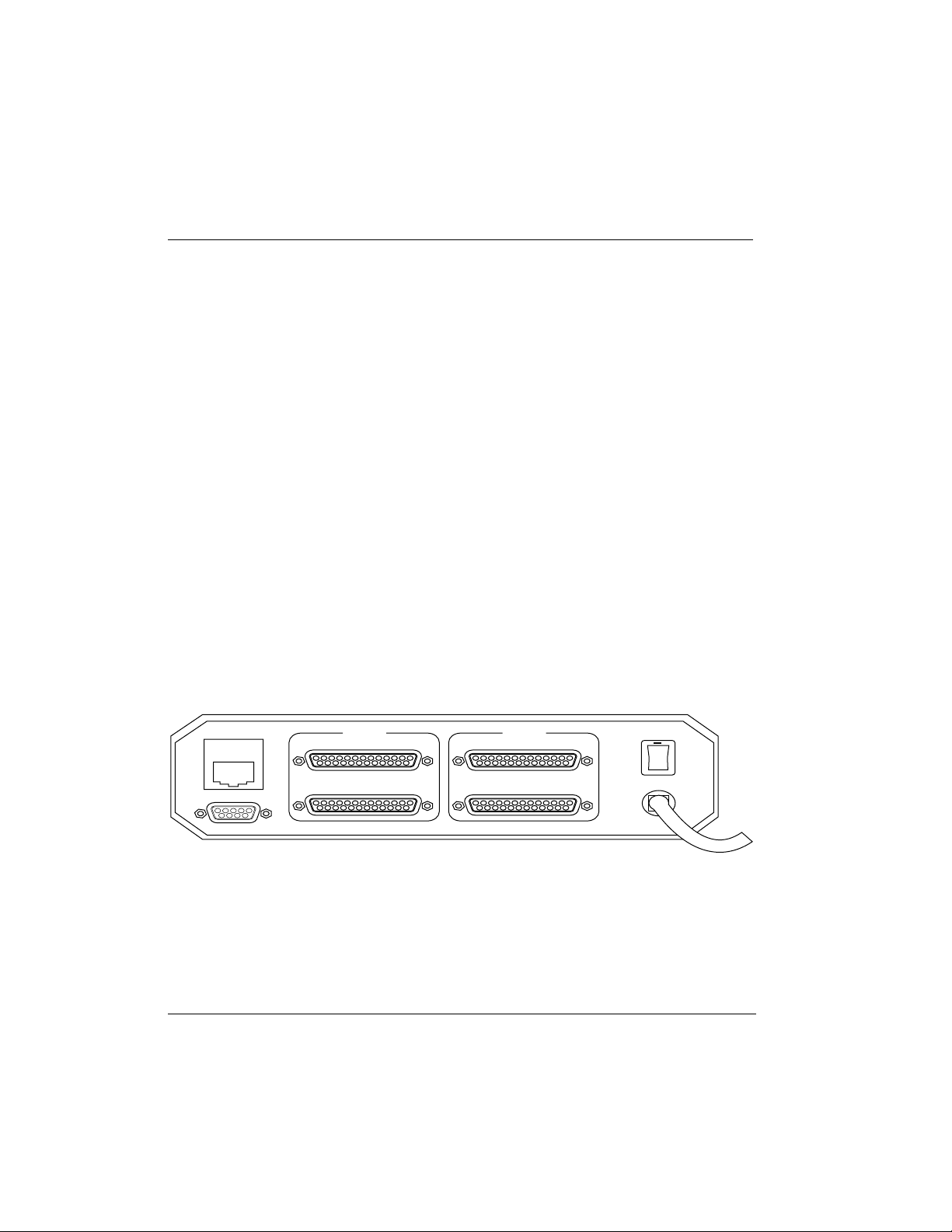
Figure 1-1: ISU 2x64 Rear Panel .................................................................................. 2
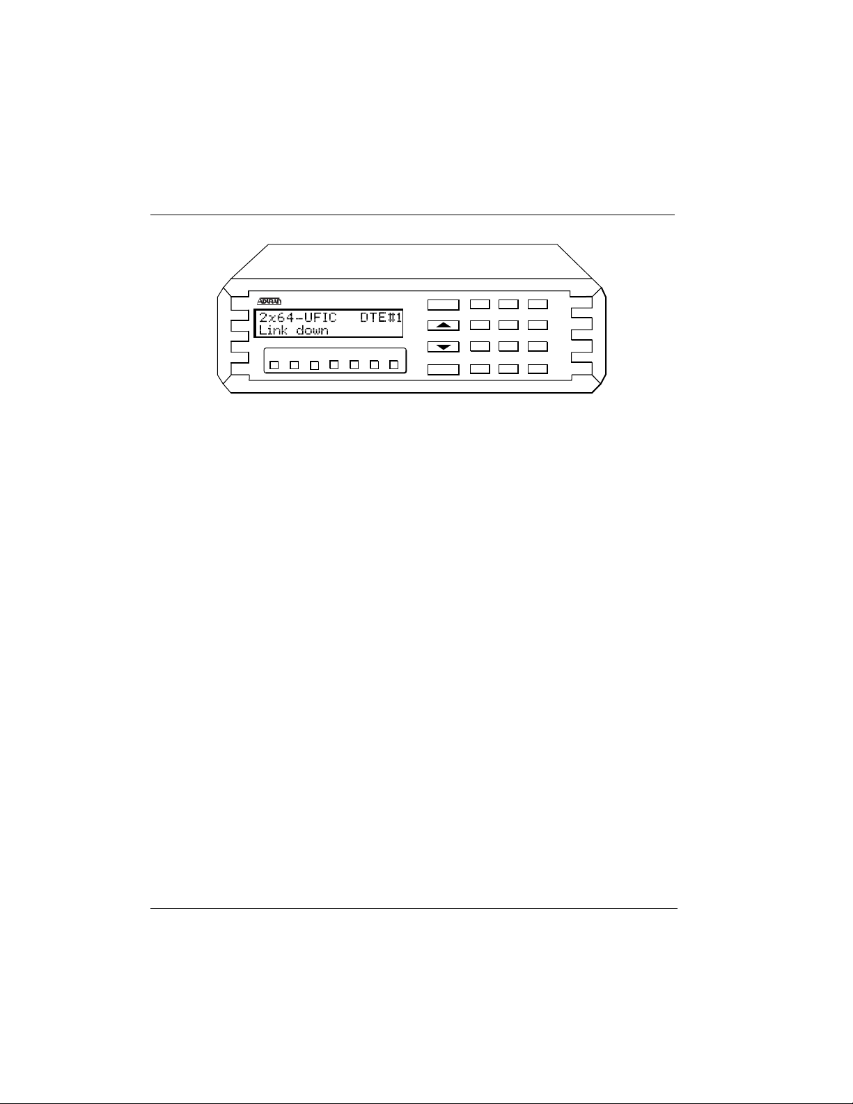
Figure 1-2: ISU 2x64 Front Panel................................................................................. 4
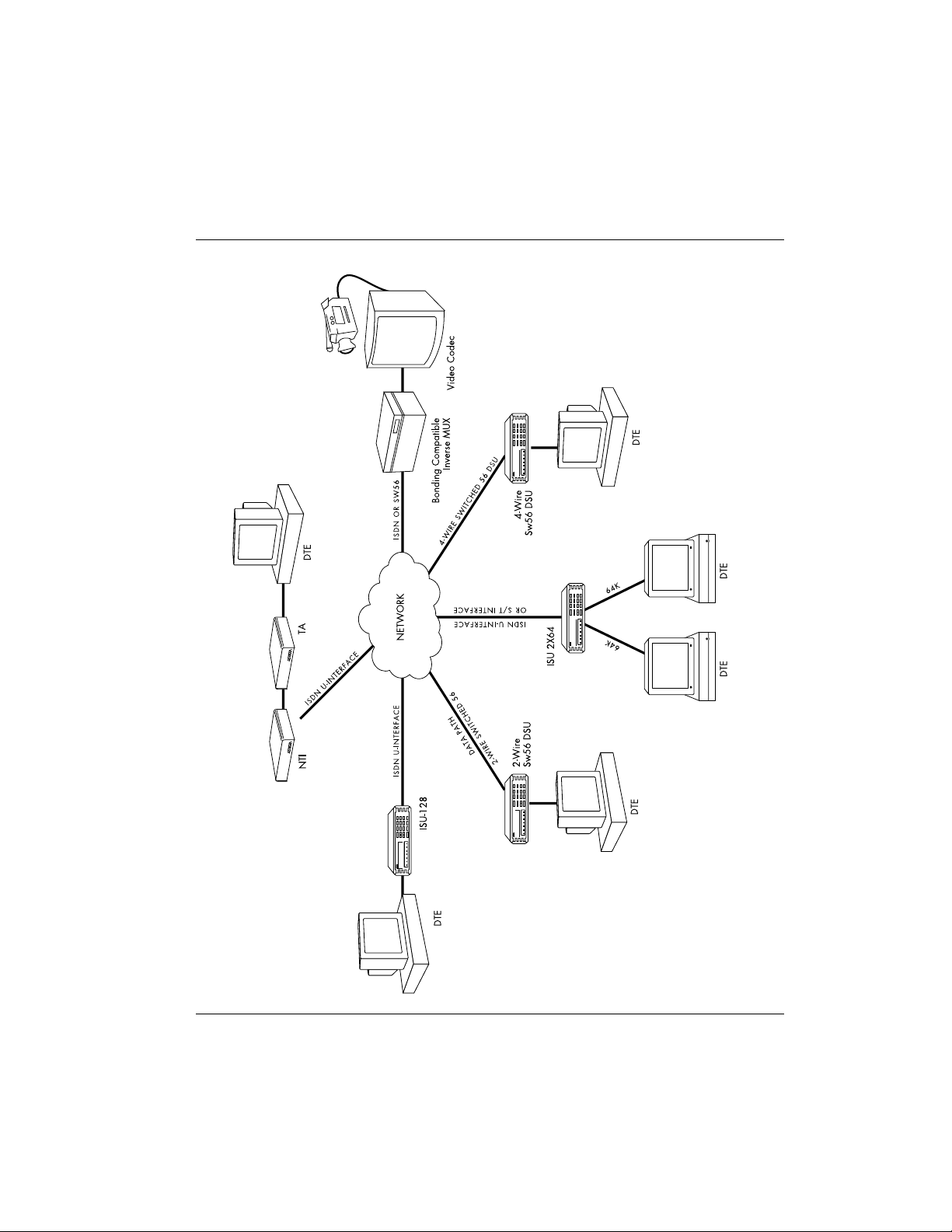
Figure 1-3: ISU 2x64 Interoperability ......................................................................... 5
Figure 3-1: VT 100 Maintenance Help Screen ......................................................... 15
Figure 4-1: Current Status Menu............................................................................... 18
Figure 4-2: VT 100 Status Screen ............................................................................... 21
Figure 4-3: VT 100 Configuration Screen................................................................. 22
Figure 5-1: VT 100 Test Menu Screen ....................................................................... 23
Figure 5-2: Test Menu Tree ........................................................................................ 24
Figure 5-3: Loopback Points ...................................................................................... 24
Figure 6-1: Dial Line Menu Tree ............................................................................... 27
Figure 6-2: VT 100 Configuration Menu Screen ..................................................... 28
Figure 6-3: LCD Configuration Menu Tree ............................................................. 29
Figure 6-4: Dial Options, RS-366 Menu Tree........................................................... 35
Figure 6-5: Dial Options, V.25 bis Menu Tree......................................................... 39
Figure 6-6: Dial Line, Auto Answer Menu Tree ..................................................... 40
Figure 6-7: Data Bits Menu Tree................................................................................ 41
Figure 6-8: V.25 bis ASYNC Menu Tree................................................................... 41
Figure 6-9: Answer Tone Menu Tree........................................................................ 44
Figure 6-10: Connect Timout Menu Tree................................................................... 45
Figure 6-11: Call Screening Menu Tree ...................................................................... 45
Figure 6-12: SBus Termination Menu Tree................................................................ 46
Figure 6-13: Leased Line Menu Tree .......................................................................... 47
Figure 6-14: Limited Distance Modem Applications ............................................... 48
Figure 6-15: Leased Application with Channel Banks............................................. 48
Figure 6-16: Asynchronous DTE Options Menu Tree.............................................. 50
Figure 6-17: Synchronous DTE Options Menu Tree ................................................ 50
Figure 6-18: Flow Control Menu Tree ........................................................................ 53
Figure 6-19: Data Format Menu Tree ......................................................................... 53
61200051L1-1D ISU 2x64 Dual Port ISDN Service Unit User Manual
v
Page 12

List of Figures
Figure 6-20: Transmit Clock Menu Tree..................................................................... 54
Figure 6-21: Protocol Menu Tree................................................................................. 55
Figure 6-22: Protocol BONDING, Mode 1 Menu Tree............................................. 57
Figure 6-23: PPP Menu Tree........................................................................................ 61
Figure 7-1: VT 100 Dial Options Screen.................................................................... 63
Figure 7-2: Dial Menu Tree ........................................................................................ 63
Figure 8-1: Quick Setup Menu Tree.......................................................................... 65
Figure 9-1: Security Menu Tree ................................................................................. 73
Figure 9-2: Remote Config Menu Tree ..................................................................... 74
Figure E-1: EIA-232 Interface ................................................................................... 119
Figure E-2: RS-530 Interface..................................................................................... 120
Figure E-3: V.35 Interface.......................................................................................... 120
Figure E-4: RS-366 Interface...................................................................................... 121
Figure E-5: RJ-45 Dial Line Connector U Interface ................................................122
vi
ISU 2x64 Dual Port ISDN Service Unit User Manual 61200051L1-1D
Page 13

List of Tables
Table 1-A: DTE Indicators....................................................................................... 3
Table 1-B: Recommended Operating Modes ....................................................... 7
Table 6-A: Rate Adaptation Protocols ................................................................... 60
Table 10-A: Troubleshooting Calls........................................................................... 84
Table E-A: EIA-232 Interface ................................................................................... 119
Table E-B: RS-530 Interface .................................................................................... 120
Table E-C: V.35 Interface.......................................................................................... 121
Table E-D: RS-366 Interface ..................................................................................... 122
Table E-E: RJ-45 Dial Line Connector U Interface ............................................... 122
Table E-F: RJ-45 Dial Line Connector S/T Interface ........................................... 123
Table E-G: Maintenance Connector........................................................................ 123
Table F-A: 5ESS Features ........................................................................................ 131
Table F-B: DMS Features......................................................................................... 132
61200051L1-1D ISU 2x64 Dual Port ISDN Service Unit User Manual
vii
Page 14

List of Tables
viii
ISU 2x64 Dual Port ISDN Service Unit User Manual 61200051L1-1D
Page 15

Chapter 1
Understanding ISDN and the ISU 2x64
ISDN OVERVIEW
The Integrated Services Digital Network (ISDN) is a public or private switched digital network. ISDN is an international standard
for digital communications, allowing a full range of enhanced services supporting voice, data, and image applications through
standard interfaces over a single pair of telephone wires. ISDN
provides a means of integrating these services and modernizing
communication networks for information movement and management efficiency.
THE ADTRAN ISU 2X64
ADTRAN’s ISU™ 2x64 is a stand-alone ISDN service unit that
connects data terminal equipment to the ISDN network. The ISU
2x64 is a dual-port ISDN terminal adapter available with an optional integrated NT1. The ISU 2x64 supports two applications at
data rates of up to 64 kbps on each DTE interface, or one application using a data rate greater than 64 kbps (maximum 128 kbps)
on a single DTE interface. Target applications for the ISU 2x64 include video conferencing, audio broadcasting, and as dual modem replacement.
61200051L1-1D ISU 2x64 Dual Port ISDN Service Unit User Manual
1
Page 16
Chapter 1.Understanding ISDN and the ISU 2x64
The ISU 2x64 features two RS-530/EIA-232 DTE interfaces and
two RS-366 dial interfaces (see Figure 1-1). An RS-530/EIA-232to-V.35 adapter is available to support V.35 DTE interfaces. Synchronous data transfer rates from 2400 bps to 128 kbps and asynchronous rates from 1200 bps to 115.2 kbps are supported on a
single DTE interface. Synchronous data transfer rates from 2400
bps to 64 kbps and asynchronous rates from 1200 bps to 57.6 kbps
are supported when using two DTE interfaces. For speeds over 64
kbps using a single DTE interface, the industry standard BONDING protocol aggregates the two 64 kbps B channels for a maximum of 128 kbps.
Dialing from the ISU 2x64 is accomplished in a variety of ways:
• Dialing manually from the front panel
• Dialing automatically from stored numbers
• Dialing through two RS-366 parallel dial interfaces (as in video conferencing applications)
• Dialing over the DTE interfaces using AT command
• V.25 bis in-band dialing (used in applications such as LAN/
WAN bridging)
• Dialing when DTR is asserted (some Bridge/Routers raise
DTR when bandwidth on their dedicated line is exceeded)
ISDN IFC POWER
MAINTENANCE
DTE#2
RS530A / RS232
RS366 DIALING PORT
DTE#1
RS530A / RS232
RS366 DIALING PORT
ISU 2x64 Rear Panel
ON
OFF
Figure 1-1
2
ISU 2x64 Dual Port ISDN Service Unit User Manual 61200051L1-1D
Page 17

Chapter 1. Understanding ISDN and the ISU 2x64
The ISU 2x64 allows the user to migrate ISDN into existing network services and data communications equipment. The ISU
2x64 interoperates with ISU 128s, Switched 56 DSUs, various
ISDN terminal adapters, and BONDING inverse multiplexers
(for example ASCEND®, PROMPTUS, and Teleos®). For
instance, in a video conferencing application, this compatibility
allows the ISU 2x64 to interoperate with networks utilizing two
Switched 56 DSUs.
The ISU 2x64 front panel accommodates a 2-line by 16-character
LCD display. Seven LED indicators monitor data flow and display the status of key DTE interface leads (see Table 1-A and Figure 1-2). A front panel keypad supports configuration, test
modes, test status, and dialing.
Table 1-A
DTE Indicators
Indicator Definition
RS Request to Send. Indicates the DTE is ready to
transmit.
CS Clear to Send. Indicates the ISU 2x64 is ready
to transmit.
TD Transmit Data. On when the DTE is transmitting
to the ISU 2x64.
RD Receive Data. On when the ISU 2x64 is receiv-
ing data from the far end.
CD Carrier Detect. On when the ISU 2x64 is con-
nected to a remote unit.
TR Data Terminal Ready from DTE. On when DTR is
active at DTE interface.
SR Data Set Ready.
61200051L1-1D ISU 2x64 Dual Port ISDN Service Unit User Manual
3
Page 18
Chapter 1.Understanding ISDN and the ISU 2x64
ISU 2X64
RS CS TD RD CD TR SR
ISU 2X64 INTEROPERABILITY
Telephone networks are evolving from analog technologies to
digital technologies such as ISDN. This transition is time-consuming and costly for the telephone companies and upgrading all locations and facilities is a lengthy process.
The ISU 2x64 bridges this transition by supporting communications with existing and future network services and equipment.
The ISU 2x64 supports communications with Switched 56 Service
and Switched 56 DSUs (2-wire and 4-wire) as well as various
ISDN terminal adapters, ISDN terminal equipment, and BONDING-compatible Inverse Multiplexers.
Figure 1-3 illustrates the ISU 2x64 operation in various switched
network services and customer premises products.
ENTER
CANCEL
123
456
789
0
*
#
ISU 2x64 Front Panel
Figure 1-2
ISU 2X64 SINGLE PORT OPERATION
The ADTRAN ISU 2x64 is designed to operate over multipoint
ISDN lines in North America that will require two Service Profile
Identification (SPID) numbers from the telephone company when
the ISDN lines are installed. These SPID numbers tell the ADTRAN ISU 2x64 which port or DTE# to route incoming and outgoing calls. See Ordering ISDN Without IOCs on page 125 for further
details on ordering multipoint ISDN service.
4
ISU 2x64 Dual Port ISDN Service Unit User Manual 61200051L1-1D
Page 19
Chapter 1. Understanding ISDN and the ISU 2x64
Figure 1-3
*
123
456
789
ENTER
DSU
#0
CANCEL
RS CS TD RD LD TR SR
ISU 2x64 Interoperability
*
123
456
789
#0
ENTER
CANCEL
ISU
RS CS TD RD LD TR SR
*
123
456
789
#0
ENTER
CANCEL
123
ENTER
ISU
456
789
RS CS TD RD LD TR SR
*
#0
CANCEL
DSU
RS CS TD RD LD TR SR
61200051L1-1D ISU 2x64 Dual Port ISDN Service Unit User Manual
5
Page 20

Chapter 1.Understanding ISDN and the ISU 2x64
When the ISU 2x64 is used on an existing ISDN line that is not
multipoint, with one SPID or no SPID numbers, additional considerations should be addressed. If DTE specific operation is
desired, the ISDN line must be converted to multipoint operation
(2 SPIDS). If not, the following applies:
1. If a single SPID is assigned, it must be entered under SPID
DTE#2 .
2. When no calls are active, the first incoming call is always directed to DTE#2 .
3. DTE#1 only accepts incoming calls when a call is active on
DTE#2 .
4. Outgoing calls can be placed without restrictions from either
port.
For applications involving only one SPID being used on a multipoint line, the SPID assigned must be entered under SPID
DTE#2 . For applications involving the S/T version (part number
1200.051L5 and 1200.051L6), no SPID(s) are used when the Euro
ISDN or VN4 switch type is selected. The call will be routed to
the appropriate port based on the directory number entered
under the local directory number (LDN) prompt . See the section
Setting the Terminal ID on page 32 for more detail on entering
SPID numbers.
RECOMMENDED OPERATING PROTOCOLS
The ISU 2x64 supports a wide range of operating modes. Many
combinations of circuit type, protocol, and data rate may be
selected. However, only the combinations shown in Table 1-B are
recommended. As noted in Table 1-B, all asynchronous rates support flow control. Flow control is required when operating at
115200 bps using V.120, PPP, MLPPP, SAP, or BONDING protocols.
Table 1-B shows that a given data rate may be achieved by more
than one protocol/rate adaptation selection. The table is organized so that selections with lower throughput delay are nearer
the top of the table for any given circuit type. Therefore, users
should choose a protocol and rate nearer the top of the list for any
given circuit type.
6
ISU 2x64 Dual Port ISDN Service Unit User Manual 61200051L1-1D
Page 21

7
Chapter 1. Understanding ISDN and the ISU 2x64
Table 1-B
Recommended Operating Modes
Call Type Protocol
DIAL-64K BONDING Sync 56000 64000
Clear Chan Sync 48000 56000 64000
PPP Sync 2400 4800 9600 19200 38400 56000 64000
V.110 Sync 2400 4800 9600 19200 38400
V.120 Sync 9600 19200 38400 48000
Tlink Sync 2400 4800 9600 19200 56000 64000
SAP Sync 38400
PPP async-sync Async 1200 2400 4800 9600 19200 38400 57600 115200f
BONDING Async 2400 4800 9600 19200 38400 57600
V.110 Async 1200 2400 4800 9600 19200 38400v
V.120 Async 1200 2400 4800 9600 19200 38400 57600 115200f
Tlink Async 1200 2400 4800 9600 19200
SAP Async 38400 57600 115200f
DIAL-56K BONDING Sync 56000
Clear Chan Sync 48000 56000
PPP Sync 2400 4800 9600 19200 38400 56000
V.110 Sync 2400 4800 9600 19200
V.120 Sync 9600 19200 38400 48000
TLINK Sync 2400 4800 9600 19200 56000
PPP async-sync Async 1200 2400 4800 9600 19200 38400 57600 115200f
BONDING Async 2400 4800 9600 19200 38400 57600
DSU 57.6 Async 57600
V.110 Async 1200 2400 4800 9600 19200
V.120 Async 1200 2400 4800 9600 19200 38400 57600 115200f
Tlink Async 1200 2400 4800 9600 19200
DIAL-64K*2 BONDING Sync 128000
MPPP Sync 128000
MPPP Async 115200
BONDING Async 115200
DIAL-56K*2 BONDING Sync 112000
MPPP Sync 112000
MPPP Async 115200
BONDING Async 115200
LEASED 64K Clear Chan Sync 48000 56000 64000
SAP Sync 2400 4800 9600 19200 38400
DSU 57.6 Async 57600
SAP Async 1200 2400 4800 9600 19200 38400 57600f 115200f
LEASED 128K Clear Chan Sync 128000
SAP Async 57600f 115200f
Sync/
Async
Rates Supported (bps)
61200051L1-1D ISU 2x64 Dual Port ISDN Service Unit User Manual
Page 22

Chapter 1.Understanding ISDN and the ISU 2x64
1. All asynchronous rates support flow control.
2. All dial-up modes support front panel, DTR, RS-366, AT
command, and V.25 dialing methods.
3. Rates marked with f require flow control.
4. Given a choice between two protocols, pick the protocol closer
to the top of the list.
5. Rate marked with v is available on Port 2 only.
8
ISU 2x64 Dual Port ISDN Service Unit User Manual 61200051L1-1D
Page 23

Chapter 2
ISDN Service
ISDN ORDERING CODES
ISDN is a complex service with many network options. Obtaining service from the local telephone company and long distance
providers can be complicated.
In North America, the development of ISDN ordering codes
(IOCs) simplifies the process of ordering ISDN service. The ISDN
Solutions Group, a consortium of ISDN equipment vendors, service providers, and Bellcore, established these codes to represent
predetermined line configurations for ISDN Basic Rate service for
specific applications.
ADTRAN and Bellcore have registered and tested eight generic
IOCs. These IOCs are supported by all major local exchange carriers as well as several independent carriers. After reviewing the
following list, order ISDN lines from the local service provider.
Request the appropriate IOC for your application. If the local service provider does not support IOCs, see Ordering ISDN Without
IOCs on page 125.
Capability S (previously Generic Data M ) ordering code is rec-
ommended for 2x64 applications. It is the most feature-rich and
supports most voice and data applications. The voice capability
is not necessary for ISU operation in 2x64 in data-only application, however it is useful in troubleshooting a mis-configured
ISDN line. In some areas, ISDN tariffs may warrant the use of
ordering codes with less features. For example, in a particular
region, there may be additional monthly expense associated with
having voice service on each B channel. If you have a data-only
61200051L1-1D ISU 2x64 Dual Port ISDN Service Unit User Manual
9
Page 24

Chapter 2.ISDN Service
application, then
Capability R (previously Generic Data I ) may
be more cost-effective.
ADTRAN has registered the following ISDN ordering codes to
support a variety of tariffs and applications:
Capability S (previously Generic Data M)
• 2B service
• Both B channels alternating voice and data
• Two directory numbers
Applications
• Host data center, internet access, bulletin board, and modem
pooling applications
• Modem capability
• Generic data transfer, including remote access and LAN/
WAN connectivity and telecommuting
Capability R (previously Generic Data I)
• 2B service
• Data only
• Two directory numbers
Applications
10
• Host data center, internet access, bulletin board, and modem
pooling applications
• Data only applications, no modem capability
• Data transfer applications, including remote access and
LAN/WAN connectivity, telecommuting
ISU 2x64 Dual Port ISDN Service Unit User Manual 61200051L1-1D
Page 25

B1 (previously Generic Data B)
• 1B service
• Data only
• One directory number
Capability C (previously Generic Data C)
• 1B service
• Alternating voice and data
• One directory number
Chapter 2. ISDN Service
I2 (previously Generic Data I-1DN)
• 2B service
• Data only
• One directory number
I2 is not available for services provided by a Northern Telecom switch. Two
directory numbers are required for 2B operation. In this case, use Capabil-
ity R.
J3 (previously Generic Data J-1DN)
• 2B service
• 1B alternating voice/data, 1B data only
• One directory number
J3 is not available for services provided by a Northern Telecom switch. Two
directory numbers are required for 2B operation. In this case, use J2 .
61200051L1-1D ISU 2x64 Dual Port ISDN Service Unit User Manual
11
Page 26

Chapter 2.ISDN Service
J2 (previously Generic Data J)
• 2B service
• 1B alternating voice/data, 1B data only
• Two directory numbers
M5 (previously Generic Data M-1DN)
• 2B Service
• 1B alternating voice/data, 1B data only
• One directory number
M5 is not available for services provided by Northern Telecom or AT&T
switches.
12
ISU 2x64 Dual Port ISDN Service Unit User Manual 61200051L1-1D
Page 27

Chapter 3
Installation
After unpacking the unit, immediately inspect it for possible
shipping damage. If damage is discovered, file a claim immediately with the shipping carrier, then contact ADTRAN Technical
Support.
Each ISU 2x64 is provided with an eight-foot power cord terminated by a three-prong plug which connects to a grounded power
receptacle.
ADTRAN ISU 2x64 part numbers 1200051L1, 1200051L2, and
1200051L5 require a grounded 115 VAC, 60 Hz receptacle for
power.
ADTRAN ISU 2x64 part numbers 1200051L3, 1200051L4 and
1200051L6 require a 230 VAC, 50 Hz receptacle for power.
NETWORK CONNECTION
An eight-pin RJ-45 modular jack on the rear panel of the ISU 2x64
allows connection to ISDN Basic Rate service provided by the
telephone company or to a leased type of service. This leased service can be dedicated 2B1Q data service or a nailed-up circuit that
provides a dedicated connection between end points such as a
limited distance modem or LAD circuit.
If using ISU 2x64, part number 1200051L1 or 1200051L3, connect
the telephone company provided ISDN Basic Rate U-Interface to
the RJ-45 connector marked ISDN IFC. An external NT1 is not
needed in this configuration.
61200051L1-1D ISU 2x64 Dual Port ISDN Service Unit User Manual
13
Page 28

Chapter 3.Installation
If using ISU 2x64, part number 1200051L2, 1200051L4, 1200051L5,
or 1200051L6, connect an ISDN Basic Rate S/T interface to the RJ45 connector marked ISDN IFC. The S/T interface can be provided from an S/T line card of an ISDN switch or PBX, or from an
NT1 network termination unit.
If using a leased service, connect the network interface to the RJ45 connector marked ISDN IFC.
See Connector Pinouts on page 119 for network connection pin
assignments.
DTE DATA CONNECTION
Data terminal equipment (DTE) is connected to the ISU 2x64 by
using the RS-530/EIA-232 interfaces or by using the external RS530-to-V.35 adapters (part number 1200072L1). A maximum
cable length of 50 feet is recommended for the RS-530/EIA-232
interfaces. If using the RS-530-to-V.35 adapter and connected to a
full specification V.35 interface, the maximum recommended
cable length is 15 feet. The pin assignments for the DTE interfaces are shown in Connector Pinouts on page 119. Be sure to configure the menu option for the connector type used in your
application. See DTE Options for Asynchronous and Synchronous
Operation on page 50.
The RS-530/EIA-232 interface and the RS-530-to-V.35 interface
supports data rates up to 128 kbps. The DTE rate is configured
from the front panel of the ISU 2x64 or by using AT commands.
See Configuration to configure the ISU 2x64 with the appropriate
data rates for your application.
To prevent possible radio frequency interference emissions, a shielded
V.35 cable is required.
14
ISU 2x64 Dual Port ISDN Service Unit User Manual 61200051L1-1D
Page 29
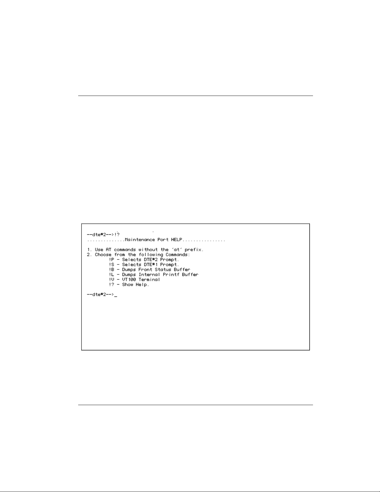
MAINTENANCE INTERFACE
The Maintenance interface is available at 9600 bps, 8 data bits, no
parity, no flow control, asynchronous format through the Maintenance port. See Connector Pinouts on page 119 for the pinout of
the Maintenance port. A VT 100 terminal or null modem can be
connected to the Maintenance port using an EIA-232 cable. This
interface can be used to set internal S-registers, dial ISDN connections, and disconnect calls. This port also allows ADTRAN Technical Support personnel to retrieve vital information from the
unit if a problem is encountered during initial configuration of
the ISU 2x64. Most problems can be solved without resorting to
this port for assistance.
The ISU 2x64 Maintenance Help Screen can be activated by typing !? at either the DTE#1 or DTE#2 prompt. The screen is shown
in Figure 3-1.
Chapter 3. Installation
Figure 3-1
VT 100 Maintenance Help Screen
61200051L1-1D ISU 2x64 Dual Port ISDN Service Unit User Manual 15
Page 30

Chapter 3.Installation
DIAL INTERFACE CONNECTION
If out-of-band RS-366 dialing is required for applications such as
videoconferencing or FAX machines, the dialing interfaces of the
host DTE should be connected to the dial ports marked RS-366.
Pin assignments for the RS-366 connector are listed in the appendix, Connector Pinouts.
16
ISU 2x64 Dual Port ISDN Service Unit User Manual 61200051L1-1D
Page 31

MENU NAVIGATION
Moving through the various menu selections on the ISU 2x64 is a
simple task. Four function keys on the left-hand side of the keypad allow the user to enter, exit, and scroll through the various
menu branches. The four function keys are defined below.
To aid the reader, function keys are represented in bold, initial caps text.
Selectable menu items and messages displayed on the LCD are represented in bold type as they appear on the LCD.
Enter Enters the selected item.
Up arrow Scrolls up a menu tree.
Down arrow Scrolls down a menu tree.
Cancel Exits (back one level) from the current
Chapter 4
Operation
branch of the menu.
Press either the Up or Down arrow to scroll through the menu
tree. To choose an item, press the corresponding number on the
keypad. The item blinks to show it is selected. Press Enter to
select the item. Press Cancel to exit back through the menu tree.
It is important to note that some features in the ISU 2x64 do not
immediately take effect upon selection. This prevents unintentional reconfiguration of the ISU 2x64 during an active call. S-
BUS termination takes effect only when the unit is powered up.
To ensure the ISU is actually performing as configured, cycle the
power off then back on again, especially after changing ISDN
61200051L1-1D ISU 2x64 Dual Port ISDN Service Unit User Manual 17
Page 32

Chapter 4.Operation
switch type, SPIDs, LDNs, or Leased/dial line. Also, items such
as bit rate, protocol, and call type take effect only at the begin-
ning of a new call.
Front Panel DTE Indicators
The front panel DTE indicators (see Figure 4-1) reflect the status
of each DTE port on the ISU 2x64. The indicators show the current state of the port being displayed from the Current Status
menu. To change the DTE indicators between the two DTE ports,
use the Up and Down arrow keys to bounce between the two
DTE ports Current Status menus. Once this menu is exited, the
DTE indicators reflect the status of the DTE# that was last shown.
See Table 1-A on page 3 for a listing of the front panel DTE indica-
tors.
18
ISU 2X64
RS CS TD RD CD TR SR
ENTER
CANCEL
123
456
789
0
*
#
Figure 4-1
Current Status Menu
The ISU 2x64 automatically updates the Current Status menu to
the DTE# that is receiving an incoming call For example, if the
Current Status menu shows the state of DTE#1, and a call is
incoming on DTE#2, the ISU 2x64 automatically changes the display to show the Current Status menu for DTE#2. Change this by
using the Up and Down arrow keys to select either DTE.
ISU 2x64 Dual Port ISDN Service Unit User Manual 61200051L1-1D
Page 33

VT 100 Menu Support
When connected to an asynchronous VT 100 terminal or VT 100
terminal emulator, use the built-in ISU 2x64 menu system for
configuration of both DTE ports. The VT 100 screens can be activated by typing AT!V while connected to either DTE port (in AT
command mode), or by typing !V at the prompt while using the
maintenance port. The maintenance port is an asynchronous port
always set to 9600 bps, 8 data bits, one stop bit, no parity, and no
flow control. By using the VT 100 screens on the maintenance
port, both DTE ports can be configured from one terminal. The
command Ctrl+P switches between DTE #1 and DTE #2.
GETTING STARTED
At power up, the ISU 2x64 runs a self test as indicated on the display. After approximately 10 seconds, Passed is momentarily displayed (if the ISU 2x64 does not pass the self test, see If Self Test
Fails on page 77). This is followed by the Current Status mode of
DTE#1. The Current Status mode DTE#2 is shown by pressing
either arrow key. This is the recommended resting place for the
unit since it shows the current operational status of the unit. For
instance, if the ISU 2x64 is not connected to the network, the Current Status menu displays ISU 2x64 DTE# (1 or 2) Link down. If
the unit is connected to the network and functioning properly, it
displays ISU 2x64 DTE# (1 or 2) Ready. A list of Current Status
messages is provided in Current Status Messages on page 95.
Pressing the Cancel key repeatedly returns the unit to the Current Status menu. While at the Current Status menu, pressing
any key, except the Cancel and # keys, repeatedly changes the
display to the top of the menu tree. Pressing the # key brings up
the Dial submenu. While in a menu tree, pressing the # key
causes the unit to return to the Current Status menu.
Chapter 4. Operation
61200051L1-1D ISU 2x64 Dual Port ISDN Service Unit User Manual 19
Page 34

Chapter 4.Operation
Status Buffer
The menu tree allows for set up and operation of the ISU 2x64
from the front panel. The main branches of the menu tree follow:
1. STATUS
2. TEST
3. CONFIG (ConÞguration)
4. DIAL
Selecting 1=STATUS from the top of the menu tree displays the
contents of the status buffer. The Up and Down arrow keys allow
the viewing of the last fifty status messages generated during the
operation of the unit. (An explanation of Status Buffer Messages
can be found in Status Buffer Messages on page 99). Pressing the
Cancel key returns you to the top of the menu. Pressing the 0 key
will clear the entries from the status buffer.
20
ISU 2x64 Dual Port ISDN Service Unit User Manual 61200051L1-1D
Page 35

Status Screen
Chapter 4. Operation
To determine the current status of the unit, press Ctrl+V to access
the Status Screen (see Figure 4-2). The Status Screen displays unit
information such as the loop status, software revision, the result
of the initial self test, and the status buffer messages. (An explanation of status buffer messages can be found in Status Buffer
Messages on page 99.)
Figure 4-2
VT 100 Status Screen
61200051L1-1D ISU 2x64 Dual Port ISDN Service Unit User Manual 21
Page 36

Chapter 4.Operation
Configuration Screen
Once the unit is selected using the terminal interface, the display
shows the Configuration Menu (see Figure 4-3). This screen
shows the current configuration, line, and call status for the
selected unit. See Configuration on page 27 for more information
about configuring the ISU 2x64.
22
Figure 4-3
VT 100 Configuration Screen
To quickly and easily configure the ISU 2x64 for most applications, see Quick Setup on page 65.
ISU 2x64 Dual Port ISDN Service Unit User Manual 61200051L1-1D
Page 37

TEST OPTIONS
Chapter 5
Testing
Selecting 2=TEST from the top of the menu tree (Figure 5-2) or
Ctrl + T from any VT 100 screen displays available local testing
options; this screen is shown in Figure 5-1.
Figure 5-1
VT 100 Test Menu Screen
61200051L1-1D ISU 2x64 Dual Port ISDN Service Unit User Manual 23
Page 38

Chapter 5.Testing
Loopback DTE
This test causes the DTE port to loop back toward user equipment. This allows a bit error rate test (BERT) to be performed
from the local end-user equipment to the ISU 2x64 to verify
proper cable connection, etc. Either a BERT tester or DTE data
packet test must be used for this test.
Loopback Network
1=STATUS
2=TEST
3=CONFIG
4=DIAL
1=Loopback DTE
2=Loopback Netw.
3=Loopback Proto
4=Loopback Remot
5=Test Remote
6=Lpbk Disable
7=NEBE/FEBE
8=Software Ver
9=Lpbk Both DTEs
10=Test 2047 Both
1=No Rem Lpbks
2=DDS Accepted
3=V.54 Accepted
4=DDS+V54 Accept
Figure 5-2
Test Menu Tree
This test forces the ISU 2x64 to loop back both the B1 and B2
channels toward the network. This can be used to allow a far-end
user to perform a BERT all the way through the network.
Loopback Protocol
This test causes data to be looped back toward the network after
passing through a selected protocol such as T-Link or BONDING.
See Figure 5-3 for loopback points.
NETWORK
24
NET
IFCE
Network
RATE
ADAPTION
Protocol
DTE
DTE
IFCE
DTE
Figure 5-3
Loopback Points
ISU 2x64 Dual Port ISDN Service Unit User Manual 61200051L1-1D
Page 39

Loopback Remote
This test causes the ISU 2x64 to issue a V.54 inband loopback
command to a far-end unit. External test equipment must be
used to generate/check test patterns. To use this feature, both
units must be configured for Clear Channel operation and the farend unit must be able to respond to V.54 loopback commands.
See Setting Protocol Options on page 55 to configure the unit for
Clear Channel operation. Press Cancel to end the test.
Test Remote
This test causes the ISU 2x64 to issue a V.54 inband loopback command to a far-end unit and BERT test the link using a built-in pattern
generator/checker. This allows a circuit to be tested without any
extra test equipment. To use this feature, both units must be configured for Clear Channel operation and the far-end unit must be able
to respond to V.54 loopback commands. See the section Setting Pro-
tocol Options to configure the unit for Clear Channel operation. The
built-in 2047 pattern generator/checker displays the number of
bytes transmitted on the top line and the number of errored bytes
received on the lower line of the front panel display. Pressing 0 will
clear the counts. Pressing the Cancel key ends the test. Pressing the
down arrow will loop down the remote unit, allowing a test to a
loopback plug. Pressing 2 will insert errors.
Chapter 5. Testing
Loopback Disable
The following options are available in Loopback Disable.
No Rem Lpbks: The ISU 2x64 ignores all V.54 and DDS loopback
commands.
DDS Accepted: The ISU 2x64 responds to DDS latching loopback
commands. This option only takes effect if the unit is in Leased
Line mode.
V.54 Accepted: The ISU responds to V.54 loopback commands.
DDS+V54 Accept: The ISU 2x64 responds to both DDS latching
loopback commands (Leased Line mode only) and V.54 loopback
commands.
61200051L1-1D ISU 2x64 Dual Port ISDN Service Unit User Manual 25
Page 40

Chapter 5.Testing
The ISU 2x64 must be optioned for Clear Channel operation for DDS
and V.54 loopbacks to take effect.
NEBE/FEBE
This test reports the quality of the network connection between
the T-1 and the switch by viewing the number of near-end block
errors (NEBE) and far-end block errors (FEBE) occurring on the
ISDN interface. An incrementing count in NEBE means the problem is in the direction of the NT-1. An incrementing count in
FEBE means the problem is in the direction of the switch.
Software Version
This test determines the software version in use on the ISU 2x64.
Loopback Both DTEs
Choosing this option loops back both DTE ports simultaneously.
Test 2047 Both
26
Choosing this option is similar to Test Remote, except both ports
are tested simultaneously.
Press Cancel to exit any of these options.
ISU 2x64 Dual Port ISDN Service Unit User Manual 61200051L1-1D
Page 41

DIAL LINE OPERATION
This section explains how to configure the ISU 2x64 when using
ISDN Basic Rate switched service. Figure 6-3 illustrates the entire
menu tree.
The following are step-by-step procedures for configuring the
unit for dial line operation, switch protocol, call type, terminal ID,
dial options, auto answer, answer tone, connect timeout, call
screening, and SBus termination.
To dial calls over the ISDN, the unit must be configured for Dial
Line. The menu path to select Dial Line operation is shown in Figure 6-1.
3=CONFIG
When using a VT 100 terminal, press Ctrl + C to access the Configuration screen, then set the Line type option to Dial Line. The
screen appears as shown in Figure 6-2.
1=Netw. options
2=DTE options
3=Protocol
4=Quick setup
5=Security
6=Remote Config
Chapter 6
Configuration
1=Dial Line
2=Leased Line
Figure 6-1
Dial Line Menu Tree
61200051L1-1D ISU 2x64 Dual Port ISDN Service Unit User Manual 27
Page 42

Chapter 6. Configuration
Setting the Switch Protocol
Figure 6-2
VT 100 Configuration Menu Screen
28
Find out what kind of ISDN switch the local CO is using by asking
the telephone administrator or telephone company representative. Configure the ISU 2x64 for either Northern Telecom DMS100, AT&T 5ESS¨, or a switch conforming to the National ISDN-1
standard (usually an AT&T 5ESS, NT DMS-100¨, or Siemens
EWSD). For switches outside of North America, use the Euro ISDN, VN4, TDX10, TDX1B, KDD, NTT, or NEC switch types.
ISU 2x64 Dual Port ISDN Service Unit User Manual 61200051L1-1D
Page 43

TATUS ‘Buffer Display’
<Use Up and Down keys to Scroll>
dte#1
EST 1=Loopback DTE
dte#2
1=Netw. options
ONFIG
2=DTE options
3=Protocol
4=Quick setup
5=Security
6=Remote Config 1=Cfg. Rmt. Unit
dte#1
DIAL
dte#2
2=Loopback Netw.
3=Loopback Proto
4=Loopback Remot
5=Test Remote
6=Lpbk Disable
7=NEBE/FEBE
8=Software Ver
9=Lpbk Both DTE
0=Test 2047 Both
1=Dial Line
2=Leased Line
dte#1
dte#2
dte#1
dte#2
dte#1
dte#2
1=Set Password
2=Lock Keypad Password Required
1=Hang up line
2=Dial number
3=Redial last #
4=Answer Call
5=Dial Stored #
6=Store/Review #
1=No Rem Lpbks
2=DDS Accepted
3=V54 Accepted
4=DDS + V54 Accept
1=Asynchronous
2=Synchronous
1=Dial 56K sync
2=Dial 64Ksync
3=Dial 112K sync
4=Dial 128K sync
5=Dial 57.6 asyn
6=Dial 115.2 asy
7=Fallback 57.6k
8=Leased 64K
9=Ldm 64K Master
Password < >
1=Clear Channel
2=BONDING mode 1
3=V.120
4=V.110
5=DSU 57.6 ASYNC
6=T-LINK
7=SAP
8=FALLBACK
9=PPP asyn-sync
dte#1
dte#2
Chapter 6. Configuration
1=AT&T 5ESS
2= DMS-100
3=National ISDN1
4=NEC Switch
1=Switch Protocl
2=Call type
3=Terminal ID
4=Busy Out
5=Dial options
6=Auto answer
7=Answer tone
8=Connect Timout 1=15 sec
9=Call Screening 1=Answer any
10=SBUS Terminati 1=100 ohm On
2=Set Password Password < >
3=Lpbk remote 1B Number < >
4=Lpbk remote 2B Number < >
5=TDX10*
6=TDX1B*
7=EuroISDN*
8=VN4*
9=KDD*
10=NTT*
dte#1
dte#2
Set SPID
Set LDN
1=Enabled
2=Disabled
dte#1
dte#2
dte#1
dte#2
dte#1
dte#2
2=30 sec (def)
3=1 minute
4=2 minute
5=4 minute
2=Ansr if SNO…9
2=100 ohm Off
1=TXINIT
2=TXFA
3=TXADD01
4=TXDEQ
5=TANULL
6=TCID
7=Async Rev
1=PPP
2=Multilink PPP
3=PPP w/Comp
dte#1 <LDN>
dte#2 <LDN>
1=Number < >
2=Password < >
Figure 6-3
LCD Configuration Menu Tree
*Only available on part number
1200051L5 and 1200051L6.
1=Speech
2=Audio
3=Data 56Kbps
4=Data 64Kbps
dte#1 <SPID>
dte#2 <SPID>
1=Front Panel
2=RS-366
3=AT commands
4=V.25
5=Disabled
1=Disabled
2=Enabled
3=Dump all calls
1=No answer tone
2=Incoming tone
3=Outgoing tone
4=Always tone
1=Clock mode
2=Channel rate 1=64k
3=SBus Terminati
1=Bit Rate
2=Connector Type 1=RS-530
3=RTS Options 1=1 ms delay
4=CTS Options 1=Forced CTS
5=CD Options 1=CD Forced on
6=DTR Options 1=Ignore DTR
7=DSR Options 1=DSR forced on
8=Transmit Clock
1=1 sec or EON
2=2 sec or EON
3=5 sec (default)
4=10 sec or EON
5=20 sec or EON
6=Wait for EON
1=Slave
2=Master
2=128k
1=100 ohm On
2=100 ohm Off
1=2400
2=4800
3=9600
4=19200
5=38400
2=V.35
3=RS-232
2=18 ms delay
2=Follows RTS
2=Normal
3=Off with LOCD
4=Off Link Down
2=Cmd when Off
3=Idle when Off
4=Off>On dial #0
5=Dial #0 if On
6=Answer if On
2=OFF Idle+Test
3=OFF Link Down
1=Normal
2=External
1=V.25 HDLC
2=V.25 ASYNC
3=V.25 BISYNC
4=V.25 HDLC FLAG
6=48000
7=56000
8=64000
9=112000
0=128000
KEY
dte#1
dte#2
This symbol means the menu items that follow can
be configured for DTE#1 or DTE#2 when entering these
portions of the menu tree. Use the up and down ARROW
keys to choose DTE#1 or DTE#2.
Press ENTER to select.
Use the CANCEL key to back up.
NOTE: Bold type represents default.
1=Bit Rate
2=Connector Type 1=RS-530
3=RTS Options 1=1 ms delay
4=CTS Options 1=Forced CTS
5=CD Options 1= CD Forced on
6=DTR Options 1=Ignore DTR
7=DSR Options 1=DSR forced on
8=Flow Control
9=Data Format 1=Data Bits 1=8 Data bits
1=300
6=19200
2=1200
7=38400
3=2400
8=57600
4=4800
9=115200
5=9600
2=V.35
3=RS-232
2=18 ms delay
2=Follows RTS
2=Normal
3=Off with LOCD
4=Off Link Down
2=Cmd when Off
3=Idle when Off
4=Off>On dial #0
5=Dial #0 if On
6=Answer if On
2=OFF Idle+Test
3=OFF Link Down
1=Hardware Flow
2=Software Flow
3=No Flow Ctrl
2=Parity Bits
3=Stop Bits
2=7 Data bits
1=None
2=Odd
3=Even
1=1 Stop bit
2=1.5 Stop bits
3=2 Stop bits
D ISU 2x64 Dual Port ISDN Service Unit User Manual 29
Page 44

Chapter 6. Cofiguration
30 ISU 2x64 Dual Port ISDN Service Unit User Manual
Page 45

Setting the Call Type
Call type is configured for both DTE#1 and DTE#2. When using
the front panel, select the appropriate DTE with either arrow key
and press Enter. When using a VT 100 terminal, select the option
number corresponding to the appropriate DTE and press Return.
The Call type can be configured four different ways, depending
on the type of service used: Speech , Audio, Data 56 kbps, or
Data 64 kbps.
Speech
Speech directs the call control software to request a Mu-law (or
A-law) speech circuit as the bearer capability for outgoing calls.
The Speech option is used with an ISDN line configured for voice
service. In some areas voice service is less expensive than data
service. A Speech call type does not guarantee an end-to-end
digital connection with some local and long distance carriers.
Audio
Audio directs the call control software to request a 3.1 kHz audio
circuit as the bearer capability for outgoing calls. The Audio
option is used with an ISDN line configured for voice service. In
some areas audio service is less expensive than data service.
Selecting Audio guarantees a digital end-to-end ISDN connection.
Chapter 6. Configuration
Data 56kbps
Data 56kbps directs the call control software to request a 64 kbps
data circuit that is rate-adapted to 56 kbps. Data 56 kbps is
intended for use in circumstances where interoperability with
Switched-56 service is desired.
Data 64kbps
The default Call type for ISDN service is Data 64 kbps. This
directs the call control software to request an unrestricted 64 kbps
circuit.
61200051L1-1D ISU 2x64 Dual Port ISDN Service Unit User Manual 31
Page 46

Chapter 6. Configuration
Smart Dial Strings
In some cases during a dial session it may be desired to change
the call type temporarily. At the end of a dialed phone number, a
#1,2,3, or 4 can be used to change the call type. A #1 changes it to
speech, #2 to Audio, #3 to 56K, and #4 to 64K.
Setting the Terminal ID
Terminal identification is assigned by the local telephone company and consists of a SPID and LDN number.
Setting the SPID
In North America, the SPID is a sequence of digits used to identify
ISDN terminal equipment to the ISDN switch. The SPID is assigned
by the local phone company when the ISDN line is installed and usually looks similar to the phone number. Obtain the SPIDs from the
telephone administrator or local telephone representative. The number of SPIDs required (0, 1, or 2) depends on how the ISDN line is configured. For instance, a point-to-point line has no SPID. Multipoint
lines may have one or two SPIDs. If the line has only one SPID, then
it must be entered in SPID DTE#2. It is recommended to use two
SPIDs with the ISU 2x64, with a SPID assigned to each DTE port.
32
When entering a SPID using the front panel, use the Up and Down
arrow keys to select between SPID DTE#1 and SPID DTE#2. Press
Enter to select the DTE. Use the keypad to enter the SPID. While
keying/editing a SPID, the Down arrow allows backspacing
through the number string to correct mistakes. The Up arrow scrolls
back to the last digit entered. After entering each SPID, press Enter.
To abort changes at any time, press Cancel. The changes are discarded, leaving the original number unchanged. If entering the SPID
using the VT 100 terminal, select the option number corresponding
to the appropriate DTE and press Return. Enter the number using
the keyboard and press Return to store the number.
Disconnect the network interface from the unit before initially entering and/
or altering the SPIDs or LDNs.
ISU 2x64 Dual Port ISDN Service Unit User Manual 61200051L1-1D
Page 47

Setting the LDN
Chapter 6. Configuration
This option allows the entry of 0, 1, or 2 LDNs. The LDN is used
when receiving BONDING calls or receiving separate calls for
each DTE connection. The LDN is the seven-digit local phone
number assigned to the line.
When entering an LDN using the front panel, use the Up and
Down arrow keys to select between LDN DTE#1 and LDN
DTE#2. Press Enter to select the DTE. Use the keypad to enter
the LDN. The Up and Down arrow keys edit the number if necessary. To store the number press Enter. To cancel a number, use
the Down arrow to backspace through the number, then press
Enter. After entering each LDN, press Enter. To abort changes at
any time, press Cancel. The changes are discarded, leaving the
original number unchanged.
When using a VT 100 terminal, select the option number corresponding to the appropriate DTE and press Return.
SPID and LDN numbers are entered in pairs and should not be
crossed between the two DTE ports. Each SPID has a unique
LDN. Enter a SPID-LDN pair for DTE#1 and a separate SPID-
LDN for DTE#2. Ensure that the SPID for DTE#1 matches the
LDN for DTE#1, and the SPID for DTE#2 matches the LDN for
DTE#2.
Disconnect the network interface from the unit before initially entering and/
or altering the SPIDs or LDNs.
Setting the Busy Out Port
The Busy Out Port is recommended for use in Hunt Group applications only. This option allows the ISU 2x64 to command the
switch to no longer route calls to the 2x64. The Busy Out Port
requires the ISDN line to be configured by the telephone company to support the Make Busy feature and a feature button
number to be assigned for activating and deactivating busy status.
61200051L1-1D ISU 2x64 Dual Port ISDN Service Unit User Manual 33
Page 48

Chapter 6. Configuration
Feature buttons are buttons that are normally available on ISDN
telephone sets. The ISU 2x64 simulates pressing a feature button
when the Busy Out Port option is changed. When the Busy Out
Port option is changed, the ISU 2x64 sends a Feature Activation
message to the switch using the feature button number stored in
S-register 23. If S-register 23 is not programmed with the correct
button number for the Make Busy feature, the switch will not
change the busy status of the ISU 2x64. The telephone company
will need to tell you which feature button number was assigned
to the Make Busy feature.
Enabled
To turn on the Make Busy feature, configure Busy Out Port for
Enabled.
Disabled
To turn off the Make Busy feature, configure Busy Out Port for
Disabled.
Multi-point lines must be used for per-port operation of the Busy Out Port
feature.
Setting the Dial Options
The ISU 2x64 can be configured to dial using the Front Panel, RS366 port, AT Commands, or V.25 bis Commands.
Front Panel
To establish and disconnect calls from the front panel keypad
configure Dial options for Front Panel. See Front Panel Dialing
Options on page 63 for more detail.
RS-366
Configuring the ISU 2x64 for RS-366 enables out-of-band dialing
over the RS-366 port. To establish and disconnect calls using the
34
ISU 2x64 Dual Port ISDN Service Unit User Manual 61200051L1-1D
Page 49

Chapter 6. Configuration
RS-366 parallel dialing port, configure the unit for RS-366 dialing.
(See Figure 6-4.) This enables the RS-366 port on the rear of the
unit. Whenever this dialing mode is enabled, data terminal ready
(DTR) must be active before a call is placed. The call may be disconnected by dropping DTR, or from the front panel by selecting
the # (pound) key to go directly to the Dial menu and selecting
1=Hang up line, then Enter.
DTE RS-366 dialers can end their string of dialed numbers in two
different ways. The end of number (EON) alerts the ISU 2x64
that the entire number has been sent. Another method is to simply stop sending numbers and allow the ISU 2x64 to time out,
then dial the number. The ISU 2x64 supports both methods of
dialed number terminations. The following options allow the
dialed number termination to be fine-tuned:
3=CONFIG
1=Netw. options
2=DTE options
3=Protocol
4=Quick setup
5=Security
6=Remote Config
1=Dial Line
2=Leased Line
1=Switch protocl
2=Call type
3=Terminal ID
4=Busy Out
5=Dial options
6=Auto answer
7=Answer tone
8=Connect Timout
9=Call Screening
10=SBus Terminati
1=Front Panel
2=RS-366
3=AT commands
4=V.25
5=Disabled
1=1 sec or EON
2=2 sec or EON
3=5 sec(default)
4=10 sec or EON
5=20 sec or EON
6=Wait for EON
Figure 6-4
Dial Options, RS-366 Menu Tree
1 sec or EON: The ISU 2x64 assumes the dial string is fully entered if more than
one second elapses since the last digit was keyed, or the unit
receives the EON command.
2 sec or EON: The ISU 2x64 assumes the dial string is fully entered if more than
two seconds elapse since the last digit was keyed, or the unit
receives the EON command.
5 sec or EON (def): The ISU 2x64 assumes the dial string is fully entered if more than
five seconds elapse since the last digit was keyed, or the unit
receives the EON command. This is the factory default setting.
10 sec or EON: The ISU 2x64 assumes the dial string is fully entered if more than
10 seconds elapse since the last digit was keyed, or the unit
receives the EON command.
61200051L1-1D ISU 2x64 Dual Port ISDN Service Unit User Manual 35
Page 50

Chapter 6. Configuration
20 sec or EON: The ISU 2x64 assumes the dial string is fully entered if more than
20 seconds elapse since the last digit was keyed, or the unit
receives the EON command.
Wait for EON: The ISU 2x64 assumes the dial string is fully entered only if the
unit receives the EON command.
AT Commands
Configuring the ISU 2x64 for AT commands enables inband dial-
ing over a DTE interface using asynchronous AT commands. AT
commands can be used to set up the ISU 2x64 as well as establish
and end a call. Calls can be disconnected from the front panel (as
described previously) or from the far-end unit. Do not set the unit
up for AT command in synchronous applications.
When AT commands are selected, the DTE port becomes dual
purpose. First, while a call is not established, the port accepts AT
commands. During this time, the CD signal is inactive. Second,
when a call is established, the port is used for data. This data
mode is indicated by the CD signal active. See the appendix AT
Commands for a listing of the supported AT commands and their
functions. In addition to the front panel, the ISU 2x64 can be configured and controlled with inband AT commands from an asynchronous DTE port just as modems are.
36
To exit data mode and enter command mode, the asynchronous
DTE device must transmit a proper escape sequence to the ISU
2x64. A specified time delay must occur between the last data
character and the first escape sequence character. This is the
guard time delay, and it can be changed by writing a value to the
S12 register. The default value for the guard time is one second.
For a valid escape sequence to occur, the DTE must transmit the
escape code character three times in succession with delay
between each character being less than the guard time. The
default escape sequence is +++.
Once command mode is entered, AT commands can be transmitted to the ISU 2x64 to configure most of the options, dial remote
ISUs, or initiate tests to check both the ISU 2x64 and the network
connections. All command lines must begin with the AT character set in either capital or lower case letters. A command line can
ISU 2x64 Dual Port ISDN Service Unit User Manual 61200051L1-1D
Page 51

Chapter 6. Configuration
be terminated at any time by transmitting the CTRL+X (ASCII
018) after the AT attention code. The ISU 2x64 ignores this command line and issues an OK response.
The command line may contain a single command or a series of
commands after the AT attention code. When a series of commands are used, the individual commands may be separated
with spaces for readability.
The maximum length for a command line is 40 characters. Each
command line is executed by the ISU 2x64 upon receipt of a terminating character.
The default terminating character is a carriage return (ASCII 013),
but it can be changed by writing a different value to register S3.
Before the terminating character is transmitted, the command
line can be edited by using the backspace character (ASCII 008) to
erase errors so the proper commands can be entered. Examples
of using AT commands are as follows.
Using an AT Command
Type AT followed by the letter of the command and numeric
value of the setting desired and then press Enter.
Example: ATI1
Returns the software version of the unit.
Using S-Registers
The configuration of the ISU 2x64 can be changed and/or
reviewed with S-registers. See the appendix S-Register List for a
description of each S-register and its corresponding range of values.
Reading an S-Register
Type ATS followed by the number of the S-register to be read followed by a question mark and press Enter.
Example: ATS0?
The ISU 2x64 uses S-register strings to store strings of digits for
stored phone numbers, SPIDs, etc.
61200051L1-1D ISU 2x64 Dual Port ISDN Service Unit User Manual 37
Page 52

Chapter 6. Configuration
Reading an S-register String
Type ATSS followed by the number of the string S-register to be
read followed by a question mark and press Enter.
To Change an S-register
Type AT S followed by the number of the S-register to be
changed, an equal sign, the numeric value to be assigned to the
register, then press Enter.
Changing a String S-register
Type ATSS followed by the number of the string S-register to be
changed, an equal sign, the numeric string to be assigned to the
register, then press Enter.
Dialing a Call by the AT Command Processor
To dial a call using the DTE terminal and AT commands; type
AT D and the telephone number on one line and press Enter.
When the dialing process begins, the front panel reads Dialing
5551212. If the call is successful, Connect is displayed on the
front panel, followed by the rate adaptation protocol in use and
the bit rate. If the call is not successful, the front panel displays
Disconnect followed by Ready. At this point the unit is ready for
another call. The status buffer can be examined to find the reason
for an unsuccessful call.
Example: ATSS80?
Example: ATS0=2
Example: ATSS80=5551212
Example: ATD5551212
38
To end an active call with the AT command processor press the
break in key sequence , +++ or the redefined key, then type ATH
and press Enter to hang up the line.
ISU 2x64 Dual Port ISDN Service Unit User Manual 61200051L1-1D
Page 53

V.25
3=CONFIG
1=Netw. options
2=DTE options
3=Protocol
4=Quick setup
5=Security
6=Remote Config
Chapter 6. Configuration
Configuring the ISU 2x64 for V.25 bis (see Figure 6-5) enables
inband dialing over a DTE interface using asynchronous or synchronous V.25 bis commands. V.25 bis can be used to establish
and end a call. Disconnecting calls can also be done from the
front panel (as described previously), from a VT 100 terminal, or
from the far-end unit.
V.25 bis dialing is used primarily by DTE with synchronous interfaces (HDLC/SDLC or BSC/BISYNC) not supporting the AT
command set, which is commonly used by asynchronous
devices. The ISU 2x64 supports V.25 bis inband dialing in accordance with Fascicle V.III-V.25 bis (Malaga-Torremolinos 1984,
Melbourne 1988).
1=Switch protocl
1=Dial Line
2=Leased Line
2=Call type
3=Terminal ID
4=Busy Out
5=Dial options
6=Auto answer
7=Answer tone
8=Connect Timout
9=Call Screening
10=SBus Terminati
1=Front Panel
2=RS-366
3=AT commands
4=V.25
5=Disabled
1=V.25 HDLC
2=V.25 ASYNC
3=V.25 BISYNC
4=V.25 HDLC FLAG
Figure 6-5
Dial Options, V.25 bis Menu Tree
Recommendation V.25 uses the following DCE/DTE control signals:
Transmitted Data . . . . . . . . . . . . . . . . . . . . . . . . . . . .Circuit 103
Received Data . . . . . . . . . . . . . . . . . . . . . . . . . . . . . .Circuit 104
Ready for Sending. . . . . . . . . . . . . . . . . . . . . . . . . . .Circuit 106
Data Set Ready. . . . . . . . . . . . . . . . . . . . . . . . . . . . . .Circuit 107
Data Terminal Ready . . . . . . . . . . . . . . . . . . . . . . . .Circuit 108/2
Calling Indicator . . . . . . . . . . . . . . . . . . . . . . . . . . . .Circuit 125
61200051L1-1D ISU 2x64 Dual Port ISDN Service Unit User Manual 39
Page 54

Chapter 6. Configuration
The ISU supports the following V.25 bis commands to control
automatic calling and answering:
CRN . . . . . . . . . . . . . . . . . . . . Call Request (number in command)
CRS . . . . . . . . . . . . . . . . . . . . . Call Request (using stored number)
PRN . . . . . . . . . . . . . . . . . . . . Program Stored Number
RLN . . . . . . . . . . . . . . . . . . . . List Stored Number
CIC . . . . . . . . . . . . . . . . . . . . . Connect Incoming Call
DIC . . . . . . . . . . . . . . . . . . . . . Disconnect Incoming Call
When using stored numbers, V.25 bis accesses stored numbers 1 through
9 used by front panel dialing. See Front Panel Dialing Options on
page 63.
The following configuration (see Figure 6-6) for Auto answer
should be selected if V.25 bis is in control of answering incoming
calls with the CIC/DIC commands, since the other settings for
Auto answer will override V.25 control of the answer function.
1=Netw. options
3=CONFIG
2=DTE options
3=Protocol
4=Quick setup
5=Security
6=Remote Config
V.25 ASYNC Dialing
V.25 bis specifies that the characters should be ASCII, 7 bits, even
parity and one stop bit. However, for versatility the ISU 2x64
allows the data bits, parity, and stop bits as defined under Data
Format. (See Figure 6-7.)
1=Dial Line
2=Leased Line
1=Switch protocl
2=Call type
3=Terminal ID
4=Busy Out
5=Dial options
6=Auto answer
7=Answer tone
8=Connect Timout
9=Call Screening
10=SBus Terminati
1=Disabled
2=Enabled
3=Dump all calls
Figure 6-6
Dial Line, Auto Answer Menu Tree
40
ISU 2x64 Dual Port ISDN Service Unit User Manual 61200051L1-1D
Page 55

3=CONFIG
3=CONFIG
1=Netw. options
2=DTE options
3=Protocol
4=Quick setup
5=Security
6=Remote Config
1=Netw. options
2=DTE options
3=Protocol
4=Quick setup
5=Securtiy
6=Remote Config
Chapter 6. Configuration
1=Bit Rate
2=Connector Type
3=RTS Options
1=Asynchronous
2=Synchronous
4=CTS Options
5=CD Options
6=DTR Options
7=DSR Options
8=Flow Control
9=Data Format
1=Data Bits
2=Parity Bits
3=Stop Bits
1=8 Data bits
2=7 Data bits
Figure 6-7
Data Bits Menu Tree
The setting in Figure 6-8 allows for V.25 bis messages in asynchronous (start/stop) data format.
1=Switch protocl
1=Dial Line
2=Leased Line
2=Call type
3=Terminal ID
4=Busy Out
5=Dial options
6=Auto answer
7=Answer tone
8=Connect Timout
9=Call Screening
10=SBus Terminati
1=Front Panel
2=RS-366
3=AT commands
4=V.25
5=Disabled
1=V.25 HDLC
2=V.25 ASYNC
3=V.25 BISYNC
4=V.25 HDLC FLAG
Figure 6-8
V.25 bis ASYNC Menu Tree
Although V.25 bis allows asynchronous data format, asynchronous DTE is more likely to support the AT command set than
V.25 bis.
V.25 SYNC HDLC Dialing
To set the Dial Options for V.25 HDLC, choose 1=V.25 HDLC
from the front panel or the VT 100 terminal (see Figure 6-8 for the
menu tree). This setting provides V.25 bis messages in bit-synchronous format (for example HDLC, SDLC, X.25). The bit-synchronous format is the most commonly used by V.25 bis.
This option specifies that the characters should be 7-bit ASCII,
with the 8th bit ignored (it may be either 0 or 1).
61200051L1-1D ISU 2x64 Dual Port ISDN Service Unit User Manual 41
Page 56

Chapter 6. Configuration
The first byte of each packet contains all ones (A = FF HEX), and
the second byte of each packet (the C byte) is either 13 HEX or 03
HEX if not the final packet.
V.25 SYNC BISYNC Dialing
To set the Dial Options for V.25 BISYNC, choose 3=V.25 BISYNC
from the front panel or the VT 100 terminal (see Figure 6-8 for
menu tree). This setting allows for V.25 bis messages in byte synchronous format (BISYNC). V.25 bis specifies that the characters
should be ASCII, 7 bits, and odd parity. This setting allows synchronous data terminal equipment which does not use HDLC to
support serial inband dialing.
V.25 HDLC FLAG
To set the Dial Options for V.25 HDLC FLAG, choose 4=V.25
HDLC FLAG from the front panel or the VT 100 terminal (see Figure 6-8 for menu tree). Configuring the ISU 2x64 for HDLC
FLAG V.25 bis enables in-band dialing over a DTE interface using
standard synchronous HDLC V.25 bis commands with 7E HEX
idle.
Disabled
This selection disables in-band dialing over the DTE interface.
Setting Auto Answer
Auto answer is configured separately for both DTE#1 and
DTE#2. Using the front panel, select the appropriate DTE with
either arrow key and press Enter. When using a VT 100 terminal,
select the option number corresponding to the appropriate DTE
and press Return.
The ISU 2x64 can be configured to automatically answer in one of
three ways: Disabled, Enabled, or Dump all calls.
Disabled
When Disabled is selected, the ISU 2x64 will not answer the call.
The AT answer command (ATA) must be issued to the ISU 2x64
for it to accept the incoming call or by selecting Answer Call
from dial menu. The ringing call can be dumped by using the
42
ISU 2x64 Dual Port ISDN Service Unit User Manual 61200051L1-1D
Page 57

Hang up line command or answered using the Answer Call
command. (These commands are found under the Dial branch of
the menu tree. See Front Panel Dialing Options on page 63.)
Enabled
When Enabled is selected, the incoming call is answered. If that
call is a BONDING call and requires two B channels, the second
call is answered. The port assigned to that second SPID-LDN
pair is disabled during the duration of the BONDING call.
Dump all calls
When Dump all calls is selected, the ISU 2x64 does not accept
any incoming calls. This keeps the line clear for outgoing calls.
Setting Answer Tone
Answer tone is configured separately for both DTE#1 and
DTE#2. Using the front panel, select the appropriate DTE with
either arrow key and press Enter. (See Figure 6-9.) When using a
VT 100 terminal, select the option number corresponding to the
appropriate DTE and press Return.
Chapter 6. Configuration
The Answer tone option enables the transmission of a modem
answer tone at the start of voice and audio calls. The purpose of
this tone is to disable echo suppression for echo cancellation on
the circuit in order to get a clear digital circuit. This may be necessary on some long distance circuits. The specifics of the tone
are 4 seconds, 2100 Hz at a -10 dB level with phase reversals
every 475 µs.
61200051L1-1D ISU 2x64 Dual Port ISDN Service Unit User Manual 43
Page 58

Chapter 6. Configuration
1=Netw. options
3=CONFIG
2=DTE options
3=Protocol
4=Quick setup
5=Security
6=Remote Config
No Answer tone (Default)
This option disables the Answer tone on all calls.
Incoming tone
This option enables the Answer tone on incoming calls.
Outgoing tone
1=Dial Line
2=Leased Line
1=Switch protocl
2=Call type
3=Terminal ID
4=Busy Out
5=Dial options
6=Auto answer
7=Answer tone
8=Connect Timout
9=Call Screening
10=SBus Terminati
Answer Tone Menu Tree
1=No Answer tone
2=Incoming tone
3=Outgoing tone
4=Always tone
Figure 6-9
Always tone
44
This option enables the Answer tone on outgoing calls.
This option enables the Answer tone on either incoming or outgoing calls.
ISU 2x64 Dual Port ISDN Service Unit User Manual 61200051L1-1D
Page 59

Setting Connect Timout
Connect Timout sets the length of time that the ISU 2x64 waits
for a far-end unit to answer an outgoing call. These choices are
illustrated in Figure 6-10.
1=Netw. options
3=CONFIG
2=DTE options
3=Protocol
4=Quick setup
5=Security
6=Remote Config
Setting Call Screening
Call Screening allows the ISU 2x64 to either answer all incoming calls
(default) or only calls originating from phone numbers stored in the
DIAL menu as stored numbers SN0 through SN9. See Front Panel
Dialing Options on page 63 to review how to store numbers. Figure
6-11 illustrates the menu tree for setting call screening.
1=Dial Line
2=Leased Line
Chapter 6. Configuration
1=Switch protocl
2=Call type
3=Terminal ID
4=Busy Out
5=Dial options
6=Auto answer
7=Answer tone
8=Connect Timout
9=Call Screening
10=SBus Terminati
1=15 sec
2=30 sec (def)
3=1 Minute
4=2 Minute
5=4 Minute
Connect Timout Menu Tree
Figure 6-10
1=Switch protocl
2=Call type
3=Terminal ID
4=Busy Out
5=Dial options
6=Auto answer
7=Answer tone
8=Connect Timout
9=Call Screening
10=SBus Terminati
1=Answer any
2=Ansr if SN0. . .9
3=CONFIG
1=Netw. options
2=DTE options
3=Protocol
4=Quick setup
5=Security
6=Remote Config
1=Dial Line
2=Leased Line
Figure 6-11
Call Screening Menu Tree
61200051L1-1D ISU 2x64 Dual Port ISDN Service Unit User Manual 45
Page 60

Chapter 6. Configuration
When Call Screening is set to Ansr if SN0. . .9, an incoming call
is not answered if the Call ID received from the switch does not
match a stored number. Depending on the switch type, the Call
ID may be presented in either a seven- or ten-digit format. The
ISU 2x64 displays the Call ID for all dumped calls in the Status
Buffer. See Status Buffer on page 20 for more information.
Because different switches handle calls and Call ID differently,
first find out if the switch uses a seven- or ten-digit Call ID format. Use the following procedure to determine if a seven- or tendigit Call ID (phone number) should be stored.
1. Select Ansr if SN0. . .9 under Call Screening.
2. Store the seven-digit number in SN0.
3. Place a call to the ISU 2x64 with the stored number to see if it
4. If the ISU 2x64 does not answer the call, check the Call ID
5. Reenter the number in SN0 as it is displayed in the Call ID
SBus Termination
answers properly.
message in the Status Buffer. More than likely, the Call ID
number will be a ten-digit number.
message and test Call Screening again.
46
Use the SBus Termination option (see Figure 6-12) to select 100
ohm termination resistors for the S/T interface on ISU 2x64 units
that are equipped for the ISDN S/T interface. These units (part
numbers 1200051L2, 1200051L4, 1200051L5, and 1200051L6) connect to the S/T interface of an NT1 device or the S/T line card.
3=CONFIG
1=Netw. options
2=DTE options
3=Protocol
4=Quick setup
5=Security
6=Remote Config
1=Dial Line
2=Leased Line
1=Switch protocl
2=Call type
3=Terminal ID
4=Busy Out
5=Dial options
6=Auto answer
7=Answer tone
8=Connect Timout
9=Call Screening
0=SBus Terminati
1=100 ohm On
2=100 ohm Off
Figure 6-12
SBus Termination Menu Tree
ISU 2x64 Dual Port ISDN Service Unit User Manual 61200051L1-1D
Page 61

Select 100 ohm On to turn on the 100 ohm termination resistance
across the S/T transmit and receive pairs. Select 100 ohm Off to
turn off the 100 ohm termination resistance across the S/T transmit and receive pairs.
The SBus Termination resistors are not present on ISU 2x64 units
equipped with the integrated NT1 (part numbers 1200051L1 and
1200051L3). Setting the SBus Termination resistance to on or off
on these units has no effect on their operation and can be ignored.
LEASED LINE SERVICE
This section explains how to configure the ISU 2x64 when using a
2B1Q leased digital service or a service providing a permanent connection between end points. The distance can be up to 18000 feet.
Chapter 6. Configuration
1=Netw. options
3=CONFIG
2=DTE options
3=Protocol
4=Quick setup
5=Security
6=Remote Config
Selecting Leased Line configures the unit for leased line service
or service providing a permanent connection between end points
such as limited distance modem or LDM service.
Follow this step-by-step procedure to configure the ISU 2x64 for
Leased Line, Clock mode, Channel rate, and S Bus Termination.
Clock mode: Slave/Master
By configuring the ISU 2x64 for Master timing, the ISU 2x64 can
provide clocking for both ends of the phone line. This Master
option is intended to be used at one end of a limited distance
1=Dial Line
2=Leased Line
1=Clock mode
2=Channel rate
3=SBus Terminati
Leased Line Menu Tree
1=Slave
2=Master
1=64k
2=128k
1=100 ohm On
2=100 ohm Off
Figure 6-13
61200051L1-1D ISU 2x64 Dual Port ISDN Service Unit User Manual 47
Page 62

Chapter 6. Configuration
modem application, where two ISU 2x64 units are directly connected without the use of channel banks (see Figure 6-14). The
far-end unit should be configured for Slave and derives its clocking from the ISU 2x64 configured as Master.
64K
DTE DTE
ISU 2x64 (U-interface)
Channel Rate = 64K
If two ISU 2x64 units are connected through channel banks, both
units should be configured for Slave mode (see Figure 6-15).
64K 64K
ISU 128
123
ENTER
456
789
RS CS TD RD LD TR SR
#0
CANCEL
*
Mixed Gauge Wire
LDM 64 Master
123
456
789
#0
64K18 kFt
*
RS CS TD RD LD TR SR
ISU 128
ENTER
CANCEL
ISU 2x64 (U-interface)
Leased 64K
Channel Rate = 64K
Figure 6-14
Limited Distance Modem Applications
64K
DTE
Channel Rate = 64K
Channel Rate
48
64K
ISU 128
RS CS TD RD LD TR SR
ISU 2x64
BIMUX DP
or Equivalent
XXXXX
XXXXX
123
ENTER
456
789
#0
CANCEL
*
XXXXXXXXX
T1
BIMUX DP
or Equivalent
XXXXX
XXXXX
XXXXXXXXX
64K
ISU 128
123
ENTER
456
789
RS CS TD RD LD TR SR
#0
CANCEL
*
ISU 2x64
Channel Rate = 64K
64K
DTE
Figure 6-15
Leased Application with Channel Banks
In Leased Line operation, the channel rate for the ISU 2x64 can be
configured for 64 kbps or 128 kbps. When the channel rate is set
to 64 kbps, each DTE port is assigned one of the bearer channels.
For example, if two ISU 2x64 units are configured for leased line
service and the channel rate is set to 64 kbps in both units, then
DTE#1 of the master unit and DTE#1 of the slave unit would be
ISU 2x64 Dual Port ISDN Service Unit User Manual 61200051L1-1D
Page 63

connected through one of the bearer channels and could utilize
up to 64 kbps of bandwidth. Likewise, DTE#2 of the master and
DTE#2 of the slave would be connected through the other bearer
channel and could also utilize up to 64 kbps of bandwidth (see
Figure 6-15).
When the channel rate is set for 128 kbps in both units, both
bearer channels are assigned to one DTE port. This assignment is
user-configured. Select a DTE rate higher than 64 kbps for the
DTE port that will run the application requiring greater than 64
kbps bandwidth. Select the same DTE port for both Master and
Slave 2x64 units. Set the unused DTE port's DTE rate to a rate
less than 64 kbps to facilitate correct operation between the two
ISU 2x64 units.
For example, if an application requiring 128 kbps was run
through DTE#1, first configure the channel rate of the leased line
to 128 kbps and set the DTE rate for DTE#1 to 128 kbps synchro-
nous. The DTE rate for DTE#2 should be set at 56 kbps or lower.
Enter these settings into both units. This allows an application to
utilize up to 128 kbps of bandwidth between DTE#1 on the mas-
ter unit and DTE#1 on the slave unit.
SBus Termination
Chapter 6. Configuration
SBus Termination selects 100 ohm termination resistors for the S/
T interface on ISU 2x64 units that are equipped for the ISDN S/T
interface. These units (part numbers 1200051L2, 1200051L4,
1200051L5, and 1200051L6) connect to the S/T interface of an
NT1 type device or the S/T line card.
Select 100 ohm On to turn on the 100 ohm termination resistance
across the S/T transmit and receive pairs. Select 100 ohm Off to
turn off the 100 ohm termination resistance across the S/T transmit and receive pairs.
The SBus Termination resistors are not present on ISU 2x64 units
equipped with the integrated NT1 (part numbers 1200051L1 and
1200051L3). Setting the SBus Termination resistance on these
units has no effect on their operation and can be ignored.
Units with S/T interface will not work in master mode.
61200051L1-1D ISU 2x64 Dual Port ISDN Service Unit User Manual 49
Page 64

Chapter 6. Configuration
DTE Options for Asynchronous and Synchronous Operation
The DTE options are configured separately for both DTE#1 and
DTE#2. When using the front panel, select the appropriate DTE
with either arrow key and press Enter. (See Figure 6-16 and 6-17.)
When using the VT 100 terminal select the option number corresponding to the appropriate DTE and press Return.
Ensure the DTE equipment is set for asynchronous operation before attempting to make an asynchronous call. Failure to do so causes the call
attempt to fail.
1=Bit Rate
2=Connector Type
3=RTS Options
4=CTS Options
5=CD Options
6=DTR Options
7=DSR Options
8=Flow Control
9=Data Format
3=CONFIG
1=Netw. options
2=DTE options
3=Protocol
4=Quick setup
5=Security
6=Remote Config
1=Asynchronous
2=Synchronous
50
3=CONFIG
Figure 6-16
Asynchronous DTE Options Menu Tree
1=Bit Rate
2=Connector Type
1=Netw. options
2=DTE options
3=Protocol
4=Quick setup
5=Security
6=Remote Config
1=Asynchronous
2=Synchronous
3=RTS Options
4=CTS Options
5=CD Options
6=DTR Options
7=DSR Options
8=Transmit Clock
Figure 6-17
Synchronous DTE Options Menu Tree
ISU 2x64 Dual Port ISDN Service Unit User Manual 61200051L1-1D
Page 65

Bit Rate
Connector Type
RTS Options
CTS Options
Chapter 6. Configuration
The Bit Rate can be set asynchronously for 300, 1200, 2400, 4800,
9600, 19200, 38400, 57600, and 115200 bps.
The Bit Rate can be set synchronously for 2400, 4800, 9600, 19200,
38400, 48000, 56000, 64000, 112000, and 128000 bps.
The ISU 2x64 can provide either an EIA-232, RS-530, or V.35 interface to a user DTE by selecting the desired connector type. The
V.35 interface requires the RS-530/232-to-V.35 adapter, part number 1200072L1.
1 ms delay causes the Clear to Send signal to change state one
millisecond after the DTE Request to Send signal changes state.
The 18 ms delay causes the Clear to Send signal to change state
18 milliseconds after the DTE Request to Send signal changes
state.
Forced CTS causes the CTS signal on the DTE connector to be
continually asserted. Follows RTS causes the CTS signal to follow the state of the RTS lead.
CD Options
CD Forced On causes the carrier detect (CD) signal to always be
asserted. Normal causes the CD signal to be asserted when a call
has been successfully established. Off with LOCD (local disconnect) causes the CD signal to be disasserted for a period of 5 seconds and then be reasserted at the termination of a call. Off Link
Down causes the CD signal to be disasserted when the ISDN
interface is not ready.
61200051L1-1D ISU 2x64 Dual Port ISDN Service Unit User Manual 51
Page 66

Chapter 6. Configuration
DTR Options
Ignore DTR causes the ISU 2x64 to disregard the state of the data
terminal ready (DTR) pin. Cmd when Off forces the unit into the
AT command processor mode when DTR is not asserted. To
return online, DTR must be asserted, followed by the AT0 command. Idle when Off forces the unit to end the current call when
DTR is no longer asserted. Off>On dial #0 allows one call
attempt to be automatically established when the DTR signal
goes from inactive to active. While DTR is active, front panel
dialing is also possible. When DTR goes inactive, any outgoing
call present is disconnected. Off>On dial #0 uses the phone
number in stored number register 0 to establish the call. To store
a number for automatic dialing, see the section Front Panel Dialing
Options. Dial #0 if On allows calls to be automatically estab-
lished when the signal is in the active state. The unit attempts to
establish a call using SN0 until the call is established or DTR goes
inactive. Answer if On only allows the unit to answer an incoming call if DTR is asserted.
DSR Options
DSR forced on causes the data set ready (DSR) signal on the DTE
connector to always be asserted. Off Idle+Test causes the DSR to
be disasserted if the ISU 2x64 is in test or there is not an active
call. Off Link Down causes the DSR signal to be disasserted
when the ISDN interface is not ready.
Flow Control (asynchronous data format)
Selecting Hardware Flow (see Figure 6-18) allows the ISU 2x64
received data to be presented to the DTE interface only when RTS
(request to send) is asserted and allows DTE transmit data to be
presented to the 2x64 when CTS is asserted. Software Flow control uses XON/XOFF inband to control data transferred between
the DTE and the ISU 2x64. Selecting No Flow Ctrl disables flow
control. Either Hardware of Software flow control should be used
when asynchronous BONDING or DTE rates higher than the
effective loop rate are used (i.e., 115.2 kbps over 112 kbps loop
rate).
52
ISU 2x64 Dual Port ISDN Service Unit User Manual 61200051L1-1D
Page 67

1=Netw. options
3=CONFIG
2=DTE options
3=Protocol
4=Quick setup
5=Security
6=Remote Config
Data Format (asynchronous)
A frame consists of a start bit, 7 or 8 Data bits, 0 or 1 Parity bit,
and 1 to 2 Stop bits. The settings for Data Bits, Parity Bits, and
Stop Bits are available as shown in Figure 6-19.
3=CONFIG
1=Netw. options
2=DTE options
3=Protocol
4=Quick setup
5=Security
6=Remote Config
1=Asynchronous
2=Synchronous
1=Asynchronous
2=Synchronous
1=Bit Rate
2=Connector Type
3=RTS Options
4=CTS Options
5=CD Options
6=DTR Options
7=DSR Options
8=Flow Control
9=Data Format
Chapter 6. Configuration
1=Bit Rate
2=Connector Type
3=RTS Options
4=CTS Options
5=CD Options
6=DTR Options
7=DSR Options
8=Flow Control
9=Data Format
Flow Control Menu Tree
1=Data Bits
2=Parity Bits
3=Stop Bits
Data Format Menu Tree
1=Hardware Flow
2=Software Flow
3=No Flow Ctrl
Figure 6-18
1=8 Data bits
2=7 Data bits
1=None
2=Odd
3=Even
1=1 Stop bit
2=1.5 Stop bits
3=2 Stop bits
Figure 6-19
Transmit Clock (synchronous data format)
Selecting the Normal option causes the ISU 2x64 to be the synchronous DTE interface transmit timing source. Transmit data is
timed from the transmit clock provided by the ISU 2x64. With
the External option selected, the ISU 2x64 slaves to an external
transmit timing source. The external clock is provided to the ISU
2x64 by the external transmit clock signal at the DTE connector.
61200051L1-1D ISU 2x64 Dual Port ISDN Service Unit User Manual 53
Page 68

Chapter 6. Configuration
This signal is echoed by the ISU 2x64 to the transmit clock signal
on the DTE connector. See Figure 6-20 for the menu tree.
1=Netw. options
3=CONFIG
2=DTE options
3=Protocol
4=Quick setup
5=Security
6=Remote Config
Autobaud
The ISU 2x64 has a DTE rate adjustment feature (autobaud)
which automatically adjusts the bit rate on the DTE port connector to match that of the connected terminal. For any terminal rate
from 300 bps through 115.2 kbps, type AT and a carriage return.
The ISU 2x64 will adjust to that rate. The DTE port must be set for
AT commands under Dial Options for autobaud to become activated on a port .
1=Asynchronous
2=Synchronous
1=Bit Rate
2=Connector Type
3=RTS Options
4=CTS Options
5=CD Options
6=DTR Options
7=DSR Options
8=Transmit Clock
Transmit Clock Menu Tree
1=Normal
2=External
Figure 6-20
54
The autobaud feature is only allowed to be active on one DTE
port at a time. If both DTE#1 and DTE#2 are set for AT commands (under Dial Options), then autobaud will be active on
DTE#2 only. To make autobaud active on DTE#1, change the Dial
Options on DTE#2 from AT commands to some other available
dialing option.
When autobaud is not active on a DTE port, the asynchronous
rate of the DTE port matches the rate programmed into the ISU
2x64 at the current time. While autobaud is running on a port,
that port meets Microsoft Windows® 95 Plug-and-Play specifications. The file MDMADTN.INF is required. To obtain this file,
contact ADTRAN Technical Support as shown on the inside back
cover of this manual.
ISU 2x64 Dual Port ISDN Service Unit User Manual 61200051L1-1D
Page 69

Setting Protocol Options
The ISU 2x64 communicates with many different types of telecommunication equipment including other ISU 2x64s, ISDN terminal adapters, Switched 56 DSUs, and BONDING-compatible
inverse multiplexers. Communicating between such diverse
types of equipment requires various rate adaptation protocols to
support various bit rates and DTE settings. See Figure 6-21 for
the menu tree. The ISU 2x64 supports the following rate adaptation protocols:
• Clear Channel (no rate adaptation protocol) (synch. only)
• BONDING mode 1 (Bandwidth on Demand Interoperability
Group)
• CCITT V.120
• CCITT V.110
• DSU 57.6 ASYNC
• T-LINK (Dial DDS DSU/CSU)
• SAP (Simple ADTRAN Protocol)
• FALLBACK
• PPP async-sync
1=Netw. options
3=CONFIG
2=DTE options
3=Protocol
4=Quick setup
5=Security
6=Remote Config
Chapter 6. Configuration
1=Clear Channel
2=BONDING mode 1
3=V.120
4=V.110
5=DSU 57.6 ASYNC
6=T-LINK
7=SAP
8=FALLBACK
9=PPP async-sync
Figure 6-21
Protocol Menu Tree
See Recommended Operating Protocols on page 6 for more information on recommended modes of operation.
The desired protocol may be selected with AT commands at the
DTE port or from the ISU 2x64 front panel. A description of protocols follows.
61200051L1-1D ISU 2x64 Dual Port ISDN Service Unit User Manual 55
Page 70

Chapter 6. Configuration
Clear Channel
Clear channel provides the entire bearer channel to the DTE without regard to data format or protocol. This provides a rate adaptation at or near the ISDN circuit rate. The primary usage for
Clear Channel in dial line mode is 56 kbps and 64 kbps synchronous. It is useful when the DTE performs its own internal synchronous protocol/rate adaptation or the ISU 2x64 is calling a 4wire Switched 56 DSU. In the leased line mode, clear channel can
provide synchronous bit rates of 56 kbps, 64 kbps, 112 kbps, and
128 kbps.
BONDING mode 1
The BONDING mode 1 protocol allows the ISU 2x64 to communicate at bit rates in excess of 64 kbps to a maximum of 128 kbps.
BONDING provides high-speed communication between ISU
2x64s, ISDN TE/TAs, and inverse multiplexing equipment supporting the BONDING protocol. The protocol allows for the use
of both synchronous and asynchronous bit rates. When the ISU
2x64 uses the BONDING mode 1 protocol, it must make two separate ISDN phone calls to seize control of both ISDN bearer channels. The protocol corrects any delays existing between the two
bearer channels and presents a single high-speed data channel to
the DTE. For successful high-speed operation, both the near- and
far-end DCE need to be configured to use BONDING mode 1
protocol. BONDING mode 1 protocol negotiation phase has
numerous timers to allow for transmission delays due to satellite
hops, international calls, etc. The timers may be adjusted if necessary by entering into BONDING mode 1 submenu. See Figure 622 for the menu tree.
56
ISU 2x64 Dual Port ISDN Service Unit User Manual 61200051L1-1D
Page 71

3=CONFIG
The timers are defined as follows:
TXINIT
This option specifies the length of time the originating endpoint
attempts to detect BONDING negotiation pattern from the
answering endpoint before determining the BONDING call has
failed. In general, this timer value should be left at the factory
default setting of 10 seconds. Select from values of 1, 2, 5, 10
(default), 20, 50, 100, and 200 seconds.
1=Netw. options
2=DTE options
3=Protocol
4=Quick setup
5=Security
6=Remote Config
Chapter 6. Configuration
1=TXINIT
1=Clear Channel
2=BONDING mode 1
3=V.120
4=V.110
5=DSU 57.6 ASYNC
6=T-LINK
7=SAP
8=FALLBACK
9=PPP async-sync
2=TXFA
3=TXADD01
4=TXDEQ
5=TANULL
6=TCID
7= Async. Rev.
Figure 6-22
Protocol BONDING, Mode 1 Menu Tree
TXFA
This option specifies the length of time both endpoints attempt to
detect the BONDING frame pattern when a call is connected
before determining the BONDING call has failed. This timer
value should be left at the factory default setting of 10 seconds.
However, when interoperating with other manufacturers’
BONDING equipment it may be necessary to lengthen this timer
to match TXADD01. Values of 1, 2, 5, 10 (default), 20, 50, 100, and
200 seconds may be selected.
TXADD01
This option specifies the length of time both endpoints wait for
the additional call to be connected at the end of negotiation
before determining the BONDING call has failed. The factory
default setting of 20 seconds is sufficient for most calls to go
through, although when dialing overseas it may be necessary to
lengthen this timer to allow for slower call routing. Values of 1, 2,
5, 10, 20, 50 (default), 100, and 200 seconds may be selected.
61200051L1-1D ISU 2x64 Dual Port ISDN Service Unit User Manual 57
Page 72

Chapter 6. Configuration
TXDEQ
This option specifies the length of time both endpoints attempt to
equalize the network delay between the bearer channels before
determining the BONDING call has failed. Values of 1, 2, 5, 10,
20, 50 (default), 100, and 200 seconds may be selected.
TANULL
This option specifies the length of time the answering endpoint
attempts to detect the BONDING negotiation pattern from the
originating endpoint before aborting to clear channel mode. In
general, this timer value should be left at the factory default setting of 10 seconds. However, it may be necessary to shorten this
timer if the DTE equipment connected to the ISU also has timer
constraints for completing non-BONDING parameter negotiation. Values of 1, 2, 5, 10 (default), 20, 50, 100, and 200 seconds
may be selected.
TCID
This option specifies the length of time both endpoints attempt to
negotiate an agreeable value for bearer channels and channel
capacities before determining the BONDING call has failed.
Select from values of 1, 2, 5 (default), 10, 20, 50, 100, and 200 seconds.
Async. Rev.
This option specifies the negotiation revision for asynchronous
BONDING. Rev. 1 specifies multi-vendor compatible negotiation.
Rev. 0 specifies ADTRAN proprietary negotiation. This option
has no effect on synchronous negotiation.
58
V.120
The V.120 protocol is a CCITT compliant rate adaptation method
providing DTE service between the ISU 2x64 and other V.120
compliant devices at rates less than the 64 kpbs ISDN bearer
channel rate. V.120 supports both synchronous and asynchronous DTE rates. See Recommended Operating Protocols on page 6
for available V.120 rates. Figure 6-21 illustrates the menu path for
selecting V.120.
ISU 2x64 Dual Port ISDN Service Unit User Manual 61200051L1-1D
Page 73

V.110
DSU 57.6 ASYNC
T-Link
Chapter 6. Configuration
The V.110 protocol is a CCITT compliant rate adaptation method
providing DTE service between the ISU 2x64 Dual Port ISDN Service Unit and other V.110 compliant devices. The V.110 protocol
supports both synchronous and asynchronous DTE rates. See the
section Recommended Operating Modes and Table 1-B for available
V.110 rates. Figure 6-21 illustrates the menu path for selecting
V.110.
The DSU 57.6 ASYNC protocol allows the ISU 2x64 to communicate asynchronously at 57.6 kbps with ADTRAN 2-and 4-wire
Switched 56 DSU products. In addition, the ISU 2x64 communicates with other ISUs over dial and leased connections using this
protocol. Figure 6-21 illustrates the menu path for selecting DSU
57.6 ASYNC.
The T-Link protocol allows the ISU 2x64 to communicate with 2-
wire Switched 56 DataPath DUs. The T-Link protocol performs
two functions:
• It adapts the data rate of sub 64 kbps DTE devices to the 64
kbps bandwidth of the ISDN bearer channel.
• For asynchronous and synchronous DTE rates up to 19.2
kbps, T-Link transmits the status of the DCE-DTE EIA leads
to facilitate flow control and maintenance.
In addition to 2-wire Switched 56 DataPath DUs, the ISU 2x64
communicates with any other device using the T-Link protocol.
Figure 6-21 illustrates the menu path for selecting T-Link.
SAP
The Simple ADTRAN Protocol (SAP) is a rate adaptation method
which provides DTE service between ISU 2x64 units at a channel
rate lower than the 64 kbps ISDN bearer. Selecting this menu
item causes the ISU 2x64 to use SAP protocol.
61200051L1-1D ISU 2x64 Dual Port ISDN Service Unit User Manual 59
Page 74

Chapter 6. Configuration
The primary usage for SAP is general purpose asynchronous rate
adaptation in a dial-up or leased environment. SAP only operates on a 64 kbps data link. Figure 6-21 illustrates the menu path
for selecting SAP.
FALLBACK
The FALLBACK asynchronous rate adaptation protocol provides
the capability to automatically establish calls with other ISDN
terminal adapters and Switched 56 DSUs, as well as other ISUs
using a single configuration. The ISU 2x64 must be optioned as
follows for FALLBACK operation:
1. Any asynchronous bit rate up to 115.2 kbps which is support-
2. Flow control must be enabled and supported by the DTE.
FALLBACK supports the following protocols based on the Call
Type: BONDING mode 1, V.120, and T-Link. Figure 6-21 illustrates the menu path for selecting FALLBACK.
When answering calls, the ISU 2x64 uses the incoming call type
to determine which rate adaptation protocols to support.
ed by the DTE.
Call Type
Data 64 k Bonding mode 1 ISUs
Data 56 k BONDING mode 1 ISUs
60
Rate Adaption Protocols
Supported
V.120 ISDN TAs
PPP async-sync PPP compatible bridges/routers
V.120 ISDN TAs
PPP async-sync PPP compatible bridges/routers
T-Link 2-wire Switched 56 DSUs
ISU 2x64 Dual Port ISDN Service Unit User Manual 61200051L1-1D
Table 6-A
Rate Adaptation Protocols
Typical Units Supported
Page 75

When originating calls to unknown units, the ISU begins its protocol selection based on its local Call Type. (Data 64k is used for
FALLBACK when selected from the Quick Setup menu.) Upon
connection at 64k Call Type, BONDING, V.120, and PPP are
attempted. If connection is not made at 64k, the ISU attempts
another call at 56k Call Type. If the protocol cannot be negotiated, the ISU hangs up the call.
Point-to-Point (PPP) Async-to-Sync
PPP provides a standard method for transporting multi-protocol
datagrams over point-to-point links. The ADTRAN PPP asyncsync protocol allows the ISU 2X64 and a PC or Macintosh® running PPP software, to communicate with a PPP-compatible
bridge or router. The PPP async-sync protocol complies with
Internet Engineering Task Force (IETF) RFC 1662. The menu path
to select PPP is shown in Figure 6-23.
The asynchronous control character map (ACCM) option is
scanned during the negotiation. When the ACCM option is seen
in a configure ACK link control packet, it is adopted by the ISU
2x64. In addition, when the ACCM option is not seen in the configure-request packet from the network, the ISU 2x64 will add it
to the packet.
Chapter 6. Configuration
1=Clear Channel
2=BONDING mode 1
3=V.120
4=V.110
5=DSU 57.6 ASYNC
6=T-LINK
7=SAP
8=FALLBACK
9=PPP async-sync
1=PPP
2=Multilink PPP
3=PPP w/Comp
3=CONFIG
1=Netw. options
2=DTE options
3=Protocol
4=Quick setup
5=Security
6=Remote Config
Figure 6-23
PPP Menu Tree
61200051L1-1D ISU 2x64 Dual Port ISDN Service Unit User Manual 61
Page 76

Chapter 6. Configuration
Point-to-Point Protocol (PPP)
The ISU 2x64 can be configured for PPP from the protocol options
of the configuration menu by selecting 1=PPP or by setting S-register S27 to a value of 0. The menu path is shown in Figure 6-23.
Multilink PPP
The ISU 2x64 can be configured for multilink PPP from the protocol options of the configuration menu by selecting 2= Multilink
PPP or by setting S-register S27 to a value of 1. (See Figure 6-23.)
In this mode, the ISU 2x64 dials a second number to establish a
second point-to-point link. Once the second PPP is established,
multilink PPP is performed over both B-channels.
The phone number for the second call should be placed in stored
number 1 (SN1). If no number is stored in SN1, the same phone
number is dialed to establish the second link.
PPP with Compression
The ISU 2x64 can be configured for PPP with compression from
the protocol options of the configuration menu by selecting
3=PPP w/Comp or by setting S-register S27 to a value of 2. The
menu path is shown in Figure 6-23.
62
ISU 2x64 Dual Port ISDN Service Unit User Manual 61200051L1-1D
Page 77

FRONT PANEL DIALING OPTIONS
Selecting 4=DIAL or pressing the # key from the front panel dis-
plays the available dialing options (see Figure 7-2). Access the VT
100 Terminal Dial Options Screen (Figure 7-1) by pressing Ctrl+D
from any screen. The dial options are only available when the
ISU is configured for Dial Line operation (not Leased Line).
Chapter 7
Dial Options
Figure 7-1
VT 100 Dial Options Screen
1=Hang up line
4=DIAL
61200051L1-1D ISU 2x64 Dual Port ISDN Service Unit User Manual 63
2=Dial number
3=Redial last #
4=Answer Call
5=Dial stored #
6=Store/Review #
Figure 7-2
Dial Menu Tree
Page 78

Chapter 7.Dial Options
Hang up line
Dial number
Redial last #
Answer Call
Dial stored #
Terminates current call.
Enter and dial a number from the keypad. If an error is made,
press the Down arrow to edit the number. After the number is
entered, press Enter to dial the number and save as stored number 9 for redialing purposes.
Redial the last number called (or attempted) from the front panel. This
number is saved as stored number 9 from the last attempted phone call.
Selectively answer incoming calls when Auto answer is configured for
disable. (Auto answer is described in the section Setting Auto Answer.)
Store/Review #
64
Dial one of ten stored phone numbers. The Up and Down arrows
permit viewing/selection of a stored number. Press Enter to dial
number and save as stored number 9 (SN9) for redial purposes.
Enter and review stored numbers. Press the Up and Down
arrows to scroll through the 10 stored numbers (SN0 - SN9). To
store a number, scroll to the desired stored number location, enter
the number to be stored, and press Enter to save the number. If
an error is made, use the Up and Down arrows to edit the number. Press Enter to save the number and exit. Press Cancel to exit
without changing the number.
ISU 2x64 Dual Port ISDN Service Unit User Manual 61200051L1-1D
Page 79

QUICK SETUP CONFIGURATION
To configure the DTE Options quickly and easily, the Quick Setup menu is available to automatically set up the nine most com-
mon DTE configurations. (See Figure 8-1.) For fine-tuning a
particular application and DTE settings, see DTE Options for Asyn-
chronous and Synchronous Operation on page 50 for step-by-step
procedures for detailed configuration of the DTE Options.
Chapter 8
Quick Setup
1=Netw. options
3=CONFIG
61200051L1-1D ISU 2x64 Dual Port ISDN Service Unit User Manual 65
2=DTE options
3=Protocol
4=Quick setup
5=Security
6=Remote Config
1=Dial 56K sync
2=Dial 64K sync
3=Dial 112K sync
4=Dial 128K sync
5=Dial 57.6 asyn
6=Dial 115.2 asy
7=Fallback 57.6k
8=Leased 64K
9=Ldm 64K Master
Figure 8-1
Quick Setup Menu Tree
Page 80

Chapter 8. Quick Setup
Quick Setup
To aid in configuring the ISU 2x64, nine common configurations
are preset for Quick Setup. These include:
• Synchronous dial operation for 56, 64, 112, and 128 kbps
• Asynchronous dial operation for 57.6 and 15.2 kbps
• 64 kbps Limited Distance Modem using Master clocking
• 64 kbps leased service
• Fallback 57.6
If indicated with an asterisk, the option requires the end user to configure
the ISDN switch type, SPID1-LDN1 and SPID2-LDN2. See the section
Setting the Dial Options.
Dial 56K sync*
When the ISU 2x64 is configured for Dial 56 Sync service, the following parameters are automatically preset:
Service type ............................................................ISDN dial line
Automatic answering.......................................................Enabled
ISDN call type...........................................................56 kbps data
Data protocol..........................................................Clear Channel
DTE mode.................................................................Synchronous
DTE connector bit rate......................................................56 kbps
DTE flow control ................................................................... none
RTS line .........................................................................1 mS delay
CTS line.......................................................................... Forced on
Transmit data clock....................................Normal clock source
V.54 Loopbacks.............................................................. Accepted
66
ISU 2x64 Dual Port ISDN Service Unit User Manual 61200051L1-1D
Page 81

Dial 64K sync*
Dial 112K sync*
Chapter 8. Quick Setup
When the ISU 2x64 is configured for Dial 64K sync service, the following parameters are automatically preset:
Service type ............................................................ ISDN dial line
Automatic answering ......................................................Enabled
ISDN call type........................................................... 64 kbps data
Data protocol..........................................................Clear Channel
DTE mode................................................................. Synchronous
DTE connector bit rate......................................................64 kbps
DTE flow control ................................................................... none
RTS line.........................................................................1 mS delay
CTS line...........................................................................Forced on
Transmit data clock....................................Normal clock source
V.54 Loopbacks...............................................................Accepted
When the ISU 2x64 is configured for Dial 112K sync service, the
following parameters are automatically preset:
Service type ............................................................ ISDN dial line
Automatic answering ......................................................Enabled
ISDN call type........................................................... 56 kbps data
Data protocol................................................. BONDING mode 1
DTE mode................................................................. Synchronous
DTE connector bit rate....................................................112 kbps
DTE flow control ................................................................... none
RTS line.........................................................................1 mS delay
CTS line..........................................................................Forced On
Transmit data clock....................................Internal clock source
BONDING timer TXINIT........................................... 10 seconds
BONDING timer TXFA.............................................. 10 seconds
BONDING timer TXADD01...................................... 50 seconds
BONDING timer TXDEQ........................................... 50 seconds
BONDING timer TANULL........................................ 10 seconds
BONDING timer TCID................................................. 5 seconds
61200051L1-1D ISU 2x64 Dual Port ISDN Service Unit User Manual 67
Page 82

Chapter 8. Quick Setup
Dial 128K sync*
Dial 57.6 asyn*
When the ISU 2x64 is configured for Dial 128K sync service, the
following parameters are automatically preset:
Service type ............................................................ISDN dial line
Automatic answering.......................................................Enabled
ISDN call type...........................................................64 kbps data
Data protocol................................................. BONDING mode 1
DTE mode.................................................................Synchronous
DTE connector bit rate....................................................128 kbps
DTE flow control .................................................................. none
RTS line .........................................................................1 mS delay
CTS line..........................................................................Forced On
Transmit data clock................................... Internal clock source
BONDING timer TXINIT...........................................10 seconds
BONDING timer TXFA .............................................. 10 seconds
BONDING timer TXADD01 ......................................50 seconds
BONDING timer TXDEQ........................................... 50 seconds
BONDING timer TANULL........................................10 seconds
BONDING timer TCID................................................. 5 seconds
When the ISU 2x64 is configured for Dial 57.6 asyn service, the following parameters are automatically preset.
68
Service type ...........................................................ISDN Dial line
ISDN call type...........................................................64 kbps data
Data Protocol......................................................................... V.120
DTE mode.............................................................. Asynchronous
Data Bits......................................................................................... 8
Parity Bits................................................................................ none
Stop Bits .........................................................................................1
DTE connector bit rate...................................................57.6 kbps
DTE flow control ................................................................... none
RTS line .........................................................................1 mS delay
CTS line..........................................................................Forced On
Dialing Mode .......................................................AT Commands
ISU 2x64 Dual Port ISDN Service Unit User Manual 61200051L1-1D
Page 83

Dial 115.2 asyn*
Fallback 57.6k*
Chapter 8. Quick Setup
When the ISU 2x64 is configured for Dial 115.2 asyn service, the
following parameters are automatically preset:
Service type ............................................................ ISDN dial line
ISDN call type........................................................... 64 kbps data
Protocol.......................................................... BONDING mode 1
DTE mode.............................................................. Asynchronous
Data Bits......................................................................................... 8
Parity Bits ................................................................................none
Stop Bits......................................................................................... 1
DTE connector bit rate.................................................115.2 kbps
DTE flow control ....................................................................none
RTS line.........................................................................1 mS delay
CTS line..........................................................................Forced On
Dialing Mode .......................................................AT Commands
When the ISU 2x64 is configured for FALLBACK 57.6K service,
the following parameters are automatically set:
Service type ...................................................................... Dial line
Automatic answering ..............................................................Yes
ISDN type.................................................................. 64 kbps data
Data protocol.....................................................................Fallback
DTE mode.............................................................. Asynchronous
Data bits......................................................................................... 8
Parity bits.................................................................................none
Stop bits ......................................................................................... 1
DTE connector rate.........................................................57.6 kbps
DTE flow control .......................................................... Hardware
RTS line.........................................................................1 mS delay
CTS line...................................................................... Follows RTS
Dialing Mode .......................................................AT Commands
61200051L1-1D ISU 2x64 Dual Port ISDN Service Unit User Manual 69
Page 84

Chapter 8. Quick Setup
Leased 64K
Ldm 64K Master
When the ISU 2x64 is configured for Leased 64K service, the following parameters are automatically preset:
Service type ................................................................Leased Line
Network clock source ...........................................................Slave
Channel rate ............................................................................. 64K
Data Protocol..........................................................Clear Channel
DDS loopbacks enabled...........................................................Yes
DTE mode.................................................................Synchronous
DTE connector bit rate......................................................64 kbps
DTE flow control ................................................................... none
RTS line .........................................................................1 mS delay
CTS line..........................................................................Forced On
Transmit data clock....................................Normal clock source
When the ISU 2x64 is configured for a point-to-point application,
such as a Limited Distance Modem arrangement, the Ldm 64K
Master option automatically presets the following parameters:
Service type ................................................................Leased Line
Network clock source ........................................................Master
Channel rate ............................................................................. 64K
Data Protocol..........................................................Clear Channel
DDS loopbacks enabled...........................................................Yes
DTE mode.................................................................Synchronous
DTE connector bit rate......................................................64 kbps
DTE flow control ................................................................... none
RTS line .........................................................................1 mS delay
CTS line..........................................................................Forced On
Transmit data clock....................................Normal clock source
70
ISU 2x64 Dual Port ISDN Service Unit User Manual 61200051L1-1D
Page 85

Factory Setup
Chapter 8. Quick Setup
To restore the ISU 2x64 to the factory default setup, power the unit
off and perform the following steps:
1. While pressing 0, power the unit on.
2. Continue pressing 0 until the front panel displays the top of
the menu tree. 1=STATUS will be blinking.
Factory default erases all stored phone numbers, SPIDs, and
LDNs, and sets parameters as follows:
Service type ............................................................ ISDN dial line
ISDN switch type .......................................................AT&T 5ESS
ISDN call type........................................................... 64 kbps data
Dialing Mode ..............................................................Front Panel
Data protocol..........................................................Clear Channel
DTE connector bit rate......................................................64 kbps
DTE flow control ................................................................... none
RTS line......................................................................... 1 ms delay
CTS line........................................................................Forced CTS
CD line ................................................................................Normal
DSR line ..........................................................................Forced on
Transmit Data Clock..................................Normal clock source
BONDING timer TXINIT........................................... 10 seconds
BONDING timer TXFA.............................................. 10 seconds
BONDING timer TXADD01...................................... 10 seconds
BONDING timer TXDEQ........................................... 50 seconds
BONDING timer TANULL........................................ 50 seconds
BONDING timer TXID................................................. 5 seconds
AT Command Escape character.................................................+
AT Command End-of-Line character value........................... 13
AT Command Line Feed character value............................... 10
AT Command Backspace character value................................ 8
RS-366 Dialing Default ...................................5 seconds or EON
Automatic Answering .....................................................Enabled
AT Command Guard time.............................................1 second
AT Command Miscellaneous Bits (S register 14) .................. 10
AT Command MSG Bits (S register 22)................................... 16
61200051L1-1D ISU 2x64 Dual Port ISDN Service Unit User Manual 71
Page 86

Chapter 8. Quick Setup
72
ISU 2x64 Dual Port ISDN Service Unit User Manual 61200051L1-1D
Page 87

SECURITY
3=CONFIG
Chapter 9
Security and Remote Configuration
The ISU 2x64 provides a front panel keypad locking feature to prevent tampering with configuration settings. The feature requires
a password to access menus below the top Current-Status menu
level. The menu options are shown in Figure 9-1.
1=Netw. options
2=DTE options
3=Protocol
4=Quick setup
5=Security
6=Remote Config
1=Set Password Password < >
2=Lock Keypad Password Required
Figure 9-1
Security Menu Tree
When the front panel keypad is locked, only the top menu is available on the LCD display. The LCD can be toggled between DTE1
and DTE2 current status displays with the cursor keys. Any key
other than a cursor key prompts the user for a password. If the entered password matches the stored password, the LCD displays a
brief message indicating that the front panel is active and the configuration menus will be displayed as normal. After configuration is complete, the users must re-enable front panel locking by
selecting 2=Lock Keypad in the Security menu. If the entered
61200051L1-1D ISU 2x64 Dual Port ISDN Service Unit User Manual 73
Page 88

Chapter 9. Security and Remote Configuration
password does not match the stored password, the LCD displays
a brief message indicating that the entered password was invalid
and the top menu is displayed.
Set Password
Set Password prompts the user to enter a numeric code that will
be required for access to configuration menus from the front panel. The code can be up to six digits long. The default state is nothing entered in the password option.
Lock Keypad
Lock Keypad locks the front panel keypad and displays a brief
message on the LCD indicating that the front panel is locked. The
top menu is displayed after the message.
REMOTE CONFIG
Remote Config (configuration) allows an ISU to be configured or
tested over the ISDN line. A special call is made that places the answer unit in remote loopback for configuration or testing. The
menu options are shown in Figure 9-2.
74
3=CONFIG
1=Netw. options
2=DTE options
3=Protocol
4=Quick setup
5=Security
6=Remote Config
1=Cfg. Rmt. Unit 2=Password < >
2=Set Password Password < >
3=Lpbk remote 1B Number < >
4=Lpbk remote 2B Number < >
1=Number < >
Figure 9-2
Remote Config Menu Tree
ISU 2x64 Dual Port ISDN Service Unit User Manual 61200051L1-1D
Page 89

Cfg. Rmt. Unit
Set Password
Lpbk remote 1B
Chapter 9. Security and Remote Configuration
Cfg. Rmt. Unit causes the ISU 2x64 to place a call to a remote ISU
for configuration. The user is prompted for the number to dial
and the password for accessing the remote unit. After the call is
placed, the local unit sends the entered password to the remote
unit. If the password is correct, the remote unit confirms the password and configuration is allowed. If the remote unit has no password defined, press Enter at the prompt.
Set Password prompts the user to enter a six digit numeric code
that musts be supplied when a remote configuration call is received. This password is the same as the password for front panel
keypad locking. The default state is nothing entered in the password option.
Lpbk remote 1B causes the ISU 2x64 to make a call to a remote ISU
and place the remote ISU into a 1B-channel loopback. When the
remoted unit is looped back, the local unit will send a test pattern
(2047) to the remote unit and verify that the test pattern comes
back uncorrupted. The user is prompted for the number to dial.
Negotiation progress is displayed while the loopback call is in
progress. Total bytes and Error bytes are displayed upon connection success. The Cancel key disconnects the call at any time.
Lpbk remote 2B
Lpbk remote 2B causes the ISU 2x64 to make a call to a remote ISU
and place the remote ISU into a 2B-channel loopback. When the
remoted unit is looped back, the local unit will send a test pattern
(2047) to the remote unit and verify that the test pattern comes
back uncorrupted. The user is prompted for the number to dial.
Negotiation progress is displayed while the loopback call is in
progress. Total bytes and Error bytes are displayed upon connection success. The Cancel key disconnects the call at any time.
61200051L1-1D ISU 2x64 Dual Port ISDN Service Unit User Manual 75
Page 90

Chapter 9. Security and Remote Configuration
76
ISU 2x64 Dual Port ISDN Service Unit User Manual 61200051L1-1D
Page 91

If Self Test Fails
Chapter 10
Troubleshooting
When the ISU 2x64 powers up, it performs an internal self test that
takes approximately 10 seconds. At the end of the test, the front
panel momentarily displays Self Test Passed.
If Self Test Passed is not displayed, the following steps will verify
whether or not the problem can be fixed locally:
1. Ensure the ISU 2x64 is receiving power.
2. Turn off the ISU 2x64 while holding down 0, then power back
on.
3. Continue to press down 0 for 15 seconds. This resets all the
internal settings to factory defaults.
4. If the ISU 2x64 still does not pass self test, call ADTRAN
Technical Support for assistance; see the back of this manual
for phone numbers.
If The ISU 2x64 Does Not Read Ready
When the ISU 2x64 has been set up and connected to a line, but the
front panel does not read Ready after a few minutes, use the following troubleshooting procedure:
61200051L1-1D ISU 2x64 Dual Port ISDN Service Unit User Manual 77
Page 92

Chapter 10. Troubleshooting
If the Euro ISDN or VN4 switch type is selected, the unit will not enter
the Ready state until a setup message is sent or received (part number
1200051L5 and 1200051L6).
1. Cycle power on the ISU 2x64, leaving it off for a minimum of
2. Disconnect the ISDN line from ISU 2x64. From a functioning
3. If the ISU 2x64 continues to display Link Down, there is a
• The ISU 2x64 software setup
• The ISU 2x64 hardware
• The wiring on your premises
• The telephone service provider’s wiring
• The telephone service provider’s hardware
• The telephone service provider’s software setup
2 seconds. Turn the power on for one full minute to ensure
the unit does not read Ready.
voice phone, call the local directory number(s) provided with
the line. Calling a good ISDN line with nothing connected
usually results in a ring or fast busy tone. If someone answers or you get a not-in-service intercept, there is probably
something wrong with the translation of the line. The phone
service provider should be able to help.
physical problem with the phone line (more than likely, a
problem with the layer 1 setup). The problem is in one or
more of the following places:
To isolate the problem, perform the following procedure:
A. Ensure the ISDN line is plugged into the ISU 2x64 con-
nector marked ISDN IFC on the back of the ISU 2x64.
B. Ensure the ISU 2x64 is configured for dial line service.
C. Try another piece of functioning ISDN equipment on
the line.
78
ISU 2x64 Dual Port ISDN Service Unit User Manual 61200051L1-1D
Page 93

Chapter 10. Troubleshooting
D. Talk to the service provider and ensure you have an
ISDN Basic Rate U-Interface with 2B1Q line coding
(wrong options are an S or T interface or AMI line coding) when using ISU 2x64 part number 1200051L1 or
1200051L3. If your ISDN line is extended from a PBX
with an S/T line card, make sure you are using ISU 2x64
part number 1200051L2, 1200051L4, 1200051L5, or
1200051L6.
E. Ensure that the phone line is connected to the actual
telephone line or PBX provided by your telephone company. If using ISU 2x64 part number 1200051L1 or
1200051L3 with the U-interface, make sure your line is
not connected through another piece of equipment such
as an NT1 in a wiring closet somewhere.
F. Ensure nothing else is bridged across the ISDN line
pair.
G. With a minimum of extra wiring, try connecting to the
ISDN line pair at the point where service provider’s
wiring ends.
H. With the ISU 2x64 connected to the ISDN line and pow-
ered up, talk to your service provider’s repair group
and inform them that your ISDN basic rate line has a
physical layer 1 problem. Ask them to check the line. If
using the ISU 2x64 1200051L1 or 1200051L3 with the Uinterface, tell them that you have an NT1-like device at
the end of the ISDN line.
4. If the ISU 2x64 continuously reads Getting TEI #1, the ISU
2x64 is physically connected to the local telephone service
provider but is unable to establish logical layer 2. The problem is in one or more of the following places:
• The ISU 2x64 software setup
• The telephone service provider’s software setup
• Hardware configuration, if the line is extended from the
switch
61200051L1-1D ISU 2x64 Dual Port ISDN Service Unit User Manual 79
Page 94

Chapter 10. Troubleshooting
To isolate the problem, use the following procedure:
A. Ensure the ISU 2x64 is set up for the correct switch type.
B. Ensure the quality of the line is satisfactory by checking
for near- and far-end block errors (NEBEs and FEBEs).
If the counts are non-zero, there may be a physical link
problem as described under Link Down (Step 3).
C. Try another piece of functioning ISDN equipment on
the ISDN line.
D. With the ISU 2x64 connected to the ISDN line and pow-
ered up, talk to the service provider’s repair group and
tell them you have an ISDN basic rate line that appears
physically okay but has no terminal endpoint identifier
(TEI). Ask them to check the line translation and ensure
that the line supports dynamic TEI allocation. If using
the ISU 2x64 part number 1200051L1 or 1200051L3 with
the U-interface, tell them that you have an NT1 and terminal adapter device connected to the line.
5. If the ISU 2x64 continuously reads Register SPID #1, the ISU
2x64 is physically connected to the local telephone service
provider and has established logical layer 2. The ISU 2x64 is
unable to establish layer 3. The problem is in one or both of
the following places:
• The ISU 2x64 software setup
• The telephone service provider’s software setup
To isolate the problem, perform the following procedure:
A. Ensure the ISU 2x64 is set up for the correct switch type.
B. Ensure the ISDN line is multipoint.
C. Ensure that the ISU 2x64 is set up with the correct
SPIDs and LDNs.
D. Try another piece of functioning ISDN equipment on
the ISDN line.
80
ISU 2x64 Dual Port ISDN Service Unit User Manual 61200051L1-1D
Page 95

E. With the ISU 2x64 connected to the ISDN line and pow-
ered up, talk to the service provider’s repair group and
tell them you have an ISDN basic rate line that appears
physically okay but is unable to register its SPID(s).
Ask them to check the line translation, ensure that the
ISDN line supports dynamic TEI allocation, and verify
the SPID(s). If using the ISU 2x64 part number
1200051L1 or 1200051L3 with the U-interface, tell them
that you have an NT1 and terminal adapter device connected to the line.
6. If the ISU 2x64 continuously reads Getting TEI #2, the ISU
2x64 has completely initialized the first phone number but is
unable to establish logical layer 2 for the second phone number. The problem is in one or both of the following places:
• The ISU 2x64 software setup
• The telephone service provider’s software setup
To isolate the problem, perform the following procedure:
A. Ensure the ISDN line is multipoint with two phone
numbers.
Chapter 10. Troubleshooting
B. Ensure that the ISU 2x64 is set up with the correct SPIDs
and LDNs.
C. Try swapping SPID1 with SPID2 and LDN1 with
LDN2. Determine if the problem is the second phone
number or the quantity of phone numbers.
D. Try another piece of functioning ISDN equipment on
the ISDN line.
E. With the ISU 2x64 connected to the ISDN line and pow-
ered up, talk to the service provider’s repair group and tell
them you have an ISDN basic rate line that appears physically okay but has no terminal endpoint identifier (TEI).
Ask them to check the line translation and ensure that the
ISDN line supports dynamic TEI allocation. If using the
ISU 2x64 part number 1200051L1 or 1200051L3 with the Uinterface, tell them that you have an NT1 and terminal
adapter device connected to the line.
61200051L1-1D ISU 2x64 Dual Port ISDN Service Unit User Manual 81
Page 96

Chapter 10. Troubleshooting
7. If the ISU 2x64 continuously reads Register SPID #2, the ISU
2x64 has completely initialized the first phone number but is
unable to establish logical layer 3 for the second phone number. The problem is in one or more of the following places:
• The ISU 2x64 software setup
• The telephone service provider’s software setup
To isolate the problem, perform the following procedure:
A. Ensure the ISDN line is multipoint with two phone
numbers.
B. Ensure that the ISU 2x64 is set up with the correct SPIDs
and LDNs.
C. Try swapping SPID1 with SPID2 and LDN1 with
LDN2. Determine if the problem is the second phone
number or the quantity of phone numbers.
D. Try another piece of functioning ISDN equipment on
the ISDN line.
E. With the ISU 2x64 connected to the ISDN line and pow-
ered up, talk to the service provider’s repair group and
tell them you have an ISDN basic rate line that appears
physically okay but is unable to register its SPID(s).
Ask them to check the line translation, ensure that the
ISDN line supports dynamic TEI allocation, and verify
the SPID(s). If using the ISU 2x64 part number
1200051L1 or 1200051L3 with the U-interface, tell them
that you have an NT1 and terminal adapter device connected to the line.
82
ISU 2x64 Dual Port ISDN Service Unit User Manual 61200051L1-1D
Page 97

If the Wrong DTE Port Answers a Call
A common mistake that can easily be made is entering the SPID/
LDN pair swapped between the two DTE ports. For example,
your telephone company has given you two SPID/LDN numbers
as follows:
SPID1 - 201555701111 LDN1 - 5557011
SPID2 - 201555702222 LDN2 - 5557022
If you were to enter the pairs for DTE#1 as SPID1/LDN2 and
SPID2/LDN1, the ISU 2x64 would get confused during incoming
calls because the SPID/LDN pair does not match. Be sure to enter
the SPID/LDN pairs for each DTE# as follows:
Enter SPID dte1 Enter LDN dte1
201555701111 5557011
Enter SPID dte2 Enter LDN dte2
201555702222 5557022
Chapter 10. Troubleshooting
Proper entry of the SPID/LDN pair is crucial to proper operation of the
ISU 2x64.
61200051L1-1D ISU 2x64 Dual Port ISDN Service Unit User Manual 83
Page 98

Chapter 10. Troubleshooting
If you Cannot Connect Calls
See Table 10-A for corrective actions if you cannot place calls.
Condition Corrective Action
Table 10-A
Troubleshooting Calls
The ISU 2x64 reads Ready but
calls cannot be placed.
Local voice calls can be transmitted, but data calls to the same
exchange cannot.
Local data calls go through, but
long distance data calls do not.
Data calls can be made, but
BONDED data calls cannot.
There is most likely a problem in the software setup (translation) at the CO switch or the network setup in the ISU
2x64.
The ISDN line is probably not set up to support data
calls.
Ensure the far end is working. If not already doing so,
place the call explicitly specifying the prefix of the long
distance service (for example, 10288 for AT&T). If this
does not work, then most likely the problem is the long
distance service provider. Another possibility is that the
local service provider is not providing long distance
access.
There is most likely a problem in the software setup (translation) at the CO switch or the network setup in the ISU
2x64.
Another possibility is that the data circuits provided are
not good enough to support the BONDING negotiation
process.
If the line has two phone numbers, make sure the second
SPID and LDN are entered correctly in SPID2 and LDN2
in the ISU 2x64.
Check with the local service provider to ensure that the
line supports two data calls. The ISU 2x64 status log
buffer shows the sequence of events that occurred. You
need to know which piece of equipment first caused the
BONDING process to terminate. The status logs from
both ends may be necessary to determine this.
84
ISU 2x64 Dual Port ISDN Service Unit User Manual 61200051L1-1D
Page 99

Chapter 11
Specifications
Network Interface
• RJ-45 for ISDN Basic Rate U-Interface, part numbers
1200051L1 and 1200051L3
• RJ-45 for ISDN Basic Rate S/T Interface, part numbers
1200051L2, 1200051L4, 1200051L5, and 1200051L6.
DTE Interface
• Two DB-25s, each RS-530/EIA-232 interfaces (V.35 interfaces
available with RS-530-to-V.35 adapters, part number
1200072L1)
Dialing Selections
• In-band DTE Dialing: V.25 bis or AT commands
• Dial Interfaces: Two RS-366 interfaces (DB-25s)
• Manual or automatic stored number dialing, DTR Assertion
• Front panel manual dialing
Data Rates (Network)
• 64 kbps (1 B channel), 128 kbps (2 B channels)
61200051L1-1D ISU 2x64 Dual Port ISDN Service Unit User Manual 85
Page 100

Chapter 11. Specifications
Data Rates (DTE)
When using single DTE interface:
• 300 bps to 115.2 kbps asynchronous
• 2400 bps to 128 kbps synchronous
When using dual DTE interfaces:
• 300 bps to 57.6 kbps asynchronous on each interface
• 2400 bps to 64 kbps synchronous on each interface
B Channel Aggregation
• BONDING Protocol Mode 1. Used for speeds over 64 kbps
• RFC 1717 Multilink PPP used for speeds over 57.6 kbps for a
Rate Adaptation
• T-Link
• CCITT V.120
• CCITT V.110
• Clear Channel
• SAP
• FALLBACK
• DSU 57.6 Async
• BONDING mode 1
• PPP Async-Sync
• Multilink PPP
from a single DTE interface.
single DTE interface.
86
Interoperability
• BONDING Mode 1-compatible Inverse Multiplexers (ASCEND, PROMPTUS, Teleos, etc.)
• Switched-56 DSUs (2-wire and 4-wire), ISU 128s, ISDN TAs
• PPP/Multilink compatible devices
Switch Compatibility
• AT&T 5ESS, NTI DMS-100, National ISDN-1, NEC, Euro ISDN*, TDX10*, TDX1B*, KDD*, NTT*, and VN4*.
*Only available on part numbers 1200051L5 and 1200051L6.
ISU 2x64 Dual Port ISDN Service Unit User Manual 61200051L1-1D
 Loading...