

Page 1

Soloist HD Pro
High Definition Broadcast Player
USER GUIDE
02.07.03
Page 2

Contents
Trademarks & Copyrights
Adtec Digital Support & Service
Telephone and Email Support
Preparing for Support
Advanced Support Plans
Standard - Priority Support Plan
Priority - 24 Support Plan (24 Hour )
Plan Comparisons
Electrical Device Compliance Notices
Safety Warnings and Cautions
Compliance Notices
FCC
Industry Canada
European Union EMC Directive Conformance Statement
Chapter 1 - Introduction
Product Overview
Operations
Applications
What ’ s Included
Other Options
Chapter 2 - Getting Started
Front Panel
Panel Diagram
Front Panel LEDs
Programming Function Buttons and Arrow Keys
System Menu
Login
Network Sub - menu
Time Sub - menu
NTP Sub - menu
Alarm Menu
Mirror Sub - menu
Com 2 Settings
Firmware Version
Decoder Menu
Decoder Status
Display Target
Video Sub - menu
Audio Sub - menu
Multicast Sub - menu
DVB - ASI Sub - menu
Back Panel Diagram
Connections
Installation
Set - up an IP Address
Set - up a Display Target
Make Connections
Chapter 3 - On - Board Control Interface
Page 3

Control Application
Zero Configuration Technology
Login
Control Interface Main Screen
Screen Elements
Help Notes
Dashboard Tab
List Builder Tab
Virtual VTR
Schedule Builder Tab
Streaming Tab
Display Tab
OSD Tab
Network Tab
System Tab
Upgrade Tab
Help Tab
Chapter 4 - How - To Guides
Connecting to the Soloist HD Pro Digital Player
Telnet Connection
Serial Connection
Browser - based User Interface
Connect Using Device Serial Number
Using the Web UI
Uploading Content
List Creation
Schedule Building
Upgrading Firmware
Factory Reset / Restore
Playback Prioritization
Advanced Use & Scripting
Setting up Synchronous Playback
Using Graphic Follows Audio
FTP Mirror Mode
Using an NTP Server
Guide to using DVC Files
CMDxxxx . DVC Files
SCHxxxx . DVC Files
LSTxxxDVC Files
PARxxxx . DVC Files
Shadow Files ( xxxx . SHD Files )
Video Connector Compatibility
Television Standards
Chapter 5 - Appendix
Appendix A - GNU General Public License
Appendix B - Media Encoding Parameters
Appendix C - Connector Specifications
Appendix D - Technical Specifications
Page 4

Trademarks & Copyrights
Copyright: (c) 2013-14 Adtec Digital. All rights reserved. This document may not, in whole or in part, be
copied, photocopied, reproduced and translated, or reduced to any electronic medium or machinereadable form without prior written consent from Adtec Digital.
Every effort has been made to ensure the accuracy of this manual. However, Adtec Digital makes no
warranties with respect to this documentation and disclaims any implied warranties of merchantability and
fitness for a particular purpose. Adtec Digital shall not be liable for any errors or for incidental or
consequential damages in connection with the furnishing, performance, or use of this manual or the
examples herein. The information in this document is subject to change without notice.
Trademarks: Soloist HD Pro is a trademark of Adtec Digital. Other product and company names may be
trademarks or registered trademarks of their respective companies. The information in this document is
subject to change without notice.
Adtec Digital Support & Service
Technical Support and Customer Service includes troubleshooting product/system functional
operations concerning Adtec equipment, embedded systems and single device issues; Service Order
generation, processing and tracking; Warranty claim processing; and on-site system evaluation and
maintenance. Technical Support plans do not include customer training programs. Programs incorporating
customer training are defined in the Training Services Policy. Customer Services technicians provide
limited instruction during a support call/email/fax in order to facilitate checking for proper equipment
operation.
Telephone and Email Support
● Telephone: 615-256-6619 ext. 166
● Email: support@adtecinc.com
● Internet: http :// www . adtecdigital . com / support / support - request - form
Adtec Digital offers telephone, email and fax support, warranty and service related inquiries during
normal business hours: 9:00am to 5:00pm Central Standard Time (CST), Monday through Friday, holidays
excepted. Support Requests can also be submitted on-line.
All inquiries will be processed in the order in which they are received and by the criteria outlined in the
Call Response Order. Inquiries and inquiry responses made after 5:00 PM (CST) weekdays, Saturday,
Sunday or on an Adtec-recognized holiday will be processed the next business day in the order received.
Callers on hold and returned calls will be prioritized by the following criteria:
● Priority-24 Subscription Customers
● Standard-Priority Subscription Customers
● All customers that have purchased Installation & Training, within 90 days of the installation.
● Adtec Certified Operators (ACO)
● Limited Level Support, Warranty & Service Requests
● Multi-device system installations that have purchased Installation & Training from Adtec
● Distributors
● System Integrators
● Multi-device systems
● Single device users
Page 5

Preparing for Support
To help expedite the troubleshooting process, please be prepared to provide the following
information to the support representative:
● Product(s) affected: Please provide a list of the Adtec Products involved including the Revision
Number for each affected product.
● Description of the Problem: Please include a detailed description of the problem. Include the
approximate time and day the problem occurred, the spot ID of the material being inserted and
what the operator reported about the incident. It is also helpful to note any recent changes to the
system. More information is always better than too little information.
● Your Contact Data: Please include contact information so we can reach you to discuss how to fix
the problem, additional troubleshooting steps that are required or to gather more complete
information regarding the problem. Please include your facility name (or call letters), your name,
title, email address, telephone number, hours of work, and other contact persons if you are not
available.
Advanced Support Plans
In addition to our basic Inquiry Response Policy, Adtec offers two advanced levels of priority inquiry
support: Standard-Priority and Priority-24. The Standard-Priority & Priority-24 plans provide
guaranteed* response times with the Priority-24 plan offering after hours and holiday support. StandardPriority support is included with the Adtec Certified Operator (ACO) training. Contact Adtec Sales to
upgrade your current support plan.
Standard-Priority Support Plan
Customers can improve upon our normal call processing times and can expedite inquiry support
responses through our subscription Standard-Priority service plan. Under this plan all telephone inquiries
are guaranteed* a telephone response of no more than 4 hours after they are received (within the
designated hours of operation). Telephone inquiries received by 4:00 PM (CST) on weekdays- excluding
Adtec holidays- are guaranteed a same-day telephone response. However, inquiry responses may be
made after hours until 8:00 PM (CST). Email and fax inquiries are limited in scope to normal business
hours, excluding holidays. Standard-Priority customers are entitled to a 10% discount on site visit and
training charges after the initial system/product installation and training. Standard-Priority customers also
receive a 3-day turnaround time guarantee* on warranty and non-warranty repairs on Adtec
manufactured equipment, excluding Studio Encoders.
Priority - 24 Support Plan (24 Hour)
In addition to our Standard-Support plan, after hours, weekend and holiday support is available
with the Priority-24 support plan. This plan is a subscription only service available for service inquiries 24
hours a day, 7 days a week. All telephone inquiries are guaranteed* a telephone response time of no
more than 2 hours. Email and fax inquiries are limited in scope to normal business hours, excluding
holidays. Calls after 5:00 PM will be forwarded to a Customer Services representative on call. Priority-24
customers are entitled to a 25% discount on site visit and training charges, after the initial
system/product installation and training. Priority-24 customers also receive a 1- day turnaround time
guarantee* on warranty and non-warranty repairs on Adtec-manufactured equipment, excluding Studio
Encoders.
Page 6

Plan Comparisons
Feature/
Plan Name
Hours 24 Hours/Day; 7
Call Response
Time
Discounted Site
Visits
Discounted
Training
Repair Service Guaranteed* 1 Day
Priority-24 Standard Priority Limited
Days/Week
Same day- 2 hours
(1st in order of call
list)
25% 10% None
25% 10% None
Turnaround
9:00 AM – 5:00 PM,
(U.S.Central Standard
Time),
Excludes Weekends &
Holidays
Same Day: 4 Hours (2nd in
order of call list)
3 Day Turnaround None
48 Hours
* A one-month free service extension will be awarded if Adtec fails to meet its service guarantee.
Page 7

Electrical Device Compliance Notices
Safety Warnings and Cautions
For your safety and the proper operation of the device:
● This unit must be installed and serviced by suitably qualified personnel only.
● Do not break the warranty seals on the device or open the lid. Only approved service technicians
are permitted to service this equipment.
● Disconnect all power before servicing the unit.
● Do not expose this device to rain or other moisture. Clean only with a dry cloth.
● If not installed in an equipment rack, install the product securely on a stable surface.
● Install the product in a protected location where no one can step or trip over the supply cord, and
where the supply cord will not be damaged.
● If a system is installed in a closed or multi-unit rack assembly, the operating ambient temperature
of the rack environment may be greater than the room ambient temperature.
● Consideration should be given to installing the unit in an environment compatible with the
maximum recommended ambient temperature of 50 degrees Celsius (122 degrees Fahrenheit).
● Install the unit in a rack so that the amount of airflow required for safe operation is not
compromised.
○ The recommended clearance on the top and sides of the unit is at least ½“ (one half
inch/one centimeter).
● Mounting of the unit in a rack should be such that no hazardous condition is achieved due to
uneven mechanical loading.
● Use only a grounded electrical outlet when connecting the unit to a power source.
● Reliable earth grounding of rack-mount equipment should be maintained.
○ Particular attention should be given to supply connection other than direct connections to
the branch circuit (e.g., use of power strips).
Compliance Notices
FCC
Note: This equipment has been tested and found to comply with the limits for a Class B digital
device, pursuant to Part 15 of the FCC Rules. These limits are designed to provide reasonable protection
against harmful interference in a residential installation. This equipment generates, uses and can radiate
radio frequency energy and, if not installed and used in accordance with the instructions, may cause
harmful interference to radio communications. However, there is no guarantee that interference will not
occur in a particular installation. If this equipment does cause harmful interference to radio or television
reception, which can be determined by turning the equipment off and on, the user is encouraged to try to
correct the interference by one or more of the following measures:
● Reorient or relocate the receiving antenna.
● Increase the separation between the equipment and receiver.
● Connect the equipment into an outlet on a circuit different from that to which the receiver is
connected.
● Consult the dealer or an experienced radio/TV technician for help.
Warning: Changes or modifications to this device not expressly approved by Adtec Digital could void the
user’s authority to operate the equipment.
Page 8

Industry Canada
This Class B digital apparatus meets all requirements of the Canadian Interference Causing
Equipment Regulations. Operation is subject to the following two conditions:(1) this device may not cause
harmful interference, and (2) this device must accept any interference received, including interference
that may cause undesired operation.
Cet appareillage numérique de la classe B répond à toutes les exigences de l'interférence canadienne
causant des règlements d'équipement. L'opération est sujette aux deux conditions suivantes: (1) ce
dispositif peut ne pas causer l'interférence nocive, et (2) ce dispositif doit accepter n'importe quelle
interférence reçue, y compris l'interférence qui peut causer l'opération peu désirée.
European Union EMC Directive Conformance Statement
This product is in conformity with the protection requirements of EU Council Directive 2004/108/EC
on the approximation of the laws of the Member States relating to electromagnetic compatibility. Adtec
Digital cannot accept responsibility for any failure to satisfy the protection requirements resulting from a
user modification of the product. This product has been tested and found to comply with the limits for
Class B Information Technology Equipment according to CISPR 22 / EN 55022.
Page 9

Chapter 1 - Introduction
Product Overview
The Soloist HD Pro is the perfect solution for High Definition Plasma and LCD digital signage or kiosk
applications. The Soloist HD Pro provides MPEG 2 and AVC/H.264 high definition and standard definition
file playback from solid state storage and IP stream decoding. Whatever your source, it automatically
scales the content to match your monitor's capabilities up to a
stunning 1080i high definition display. The media can easily be loaded, managed, and scheduled for
playout using the onboard, web-based Control Interface.
Operations
● Play and/or Decode MPEG-2 and AVC H.264 HD: Step up to stunning playback of high
definition AVC/H.264 and MPEG-2 media.
● Automatically Scale SD to HD: Play both SD and HD content with the same player which
automatically sizes video with advanced scalar algorithms to the desired output resolution from
480i up to full HD 1080i.
● Control Playout:The Soloist HD Pro includes a built-in command interface and scheduler that can
play a list of files and loop indefinitely, or be triggered from external control systems from the
parallel or serial ports.
● Tune into IPTV Networks: Tune in and decode IP Multicast HD content with fall back playout of
stored content.
● Synchronize Playback: Deploy multiple players on the same network and get synchronized
playback of your content.
● Sound Professional: Decode stereo MPEG 1 Layer 2, Dolby Digital and decode or downmix Dolby
5.1.
● Manage Content: The included on-board web control application lets you manage your media,
play lists and schedules on the player while controlling the playout. With the ability to view log files
and real-time playout data, day-to-day operations and troubleshooting is streamlined.
Applications
The Soloist HD Pro is the ideal platform for:
● Retail: Impress customers with high definition (HD) retail digital signage and point of purchase
advertising on Plasma and LCD monitors.
● Tradeshows and Museums: Get the detail you need with native HD playback or upscaled
standard definition (SD) for kiosks and interactive displays.
● Private IP Networks: Stream live content to the Soloist HD Pro over IP for point-to-point or
multicast playout. Fall back to playback of stored content when live stream is off.
Page 10

What’s Included
The Soloist HD Pro ships with the following:
● Soloist HD Pro Digital Media Server
● Terminal Connection Kit 1:
○ Power cord
○ Ethernet cable
○ serial adapter
○ three 5-pin removable stereo terminal audio plugs
● Web-based command and control interface
Other Options
● edjeShelf w/Hardware: Holds 1 Soloist HD Pro unit, power cord and provides cable tie slots (PN: 200-024-
1AKIT)
Page 11
Chapter 2 - Getting Started
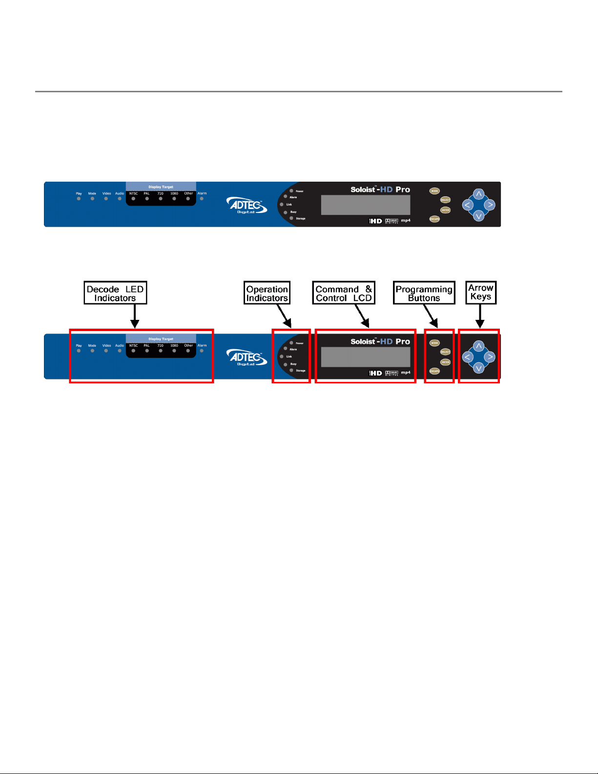
Front Panel
The Function Buttons and Directional Keypad of Soloist HD Pro are used to configure and monitor the
configurations and output of the device.
Panel Diagram
Front Panel LEDs
The Soloist HD Pro Front Panel consists of Operational Indicator LEDs, LCD display, and groups of
programming and arrow control buttons.
System / Operation Status Indicator LEDs
Power
Alarm
Link
Green: Power is on
Off (not lit): Power is off
Off (not lit): no alarm
Yellow: minor alarm
Red: major alarm
Green: Ethernet Link Detected
Busy
Network traffic
Storage / Aux
Off (not lit): No Ethernet Connection detected
Orange / Green Flashing: Unit is busy /
Off (not lit): No detected network traffic
Off (not lit)
Page 12
Decode Indicator LEDs
Play
Green: Unit is playing from internal stored
content
Off (not lit): Power is not playing
Mode / Mulicast
Green: Unit is decoding / playing an IP
Multicast
Orange: Unit is decoding / playing a DVB ASI
Feed
Off (not lit): Not decoding / playing ASI or IP
Video
Green: Unit is decoding / playing video
Off (not lit): Unit is in idle mode or not
outputting video
Audio
Display Target
Alarm
Programming Function Buttons and Arrow Keys
Green: Unit is decoding and outputting Audio
Off (not lit): Unit is not outputting Audio
Green: Corresponding resolution LED NTSC,
PAL, 720, 1080, Other will be lit when
outputting configured video resolution
Off (not lit): Unit is decoding / playing video
Off (not lit): no alarm
Yellow: minor alarm
Red: major alarm
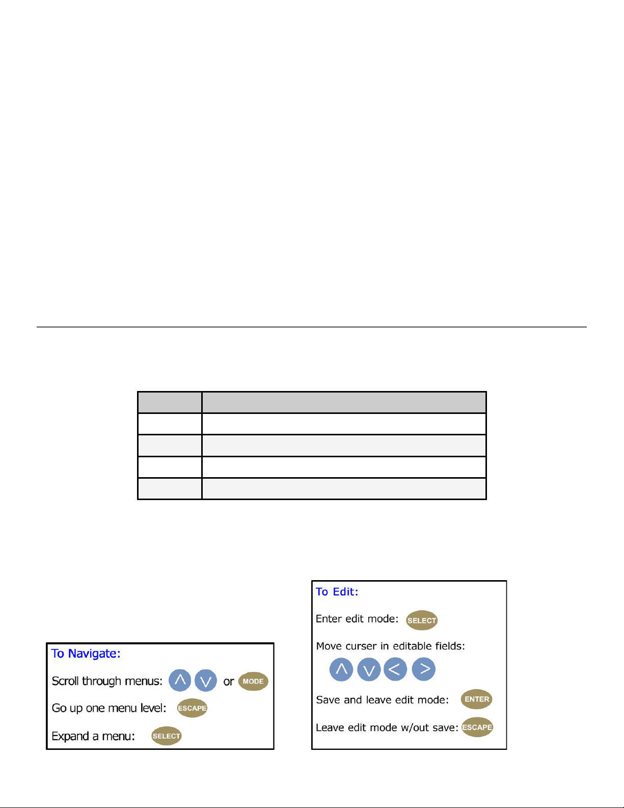
The Soloist HD Pro has an LCD display on the front panel. Using the Mode, Select,Enter, Escape buttons
and directional buttons, you can navigate the front panel menu and control the unit
Control Function
Mode Cycles through the available menus
Select selects a menu or sub-menu
Enter enter a value placed into a menu field
Escape return one level within a menu or to the main menu
Directional Keypad
Arrow keys control the cursor on the LCD display and are used to page through the options in a
menu/sub-menu and to place entries in fields.
Page 13

Unit Security
Rules:
● The Soloist HD Pro is always logged in on startup.
● If the device has logged out due to accident, or a login duration timer being set (see below), you
will need to log back in. To log in from a logged-out status follow the key sequence below. Note
that the key sequence spells the word U-S-E-R.
Step Action
1 Press <Select>
2 Press <Up> arrow
3 Press <Select>
4 Press <Enter>
5 Press <Right> arrow
6 Press <Enter>
The front panel also has a login duration capability. This setting allows you to specify a time frame in
which the unit will automatically log itself out if it receives no control inputs via the front panel or API
session.
Possible Values:
0 (Zero): The unit will not auto-logout
1-9: The number of minutes until logout if no input is received.
Main System Banner Menu
The main banner menu is a non-editable display. It displays the current installed and applied firmware
version the unit is running as well as the product name.
Key Functions
While in the main menu, the following navigation keys have special meaning in the operation of the Soloist
HD Pro.
Increase LCD Contrast / Brightness
1. 1. Press and hold <Mode> and <Escape> buttons
2. 2. Press <Up> arrow to desired level
Decrease LCD Contrast / Brightness
1. 1. Press and hold <Mode> and <Escape> buttons
2. 2. Press <Down> arrow desired level
Reset the unit
1. 1. Press and hold <Mode> and <Escape> buttons
2. 2. Press the <Right> arrow
3. 3. Release all three buttons at the same time
Page 14

System Menu
The following diagram illustrates the structure and flow of the System Menu on the Adtec Soloist HD
Pro device:
Login
Item Function Options API Command
Login If the front panel is in a ‘logged out’
state, all configurations are read only.
User must login to change values.
Login
Duration
Specifies the time-out value for
automatically logging out of the front
panel once a user logs in for security
purposes. Setting a time of 0 disables
automatic logout capabilities
N/A N/A
0 - 9 ( minutes ) *.SYSD LDR
Network Sub-menu
Item Function Options API Command
Ethernet
IP Address
Ethernet
IP Mask
IP address of unit on your
network
Defines the units’ Ethernet
Port relative to the rest of
your network
user-defined using<left/right
arrow> and<select> buttons
default is 192.168.10.48
user-defined using<left/right
arrow> and<select> buttons
default is 255.255.255.0
*.SYSD IPA 0
*.SYSD IPM 0
Ethernet
DHCP
GigE IP
Address
GigE IP
Mask
GigE
DHCP
Gateway
IP Address
Dynamic Host Configuration
Protocol; allows the device
to self-locate network
Ethernet parameters
GigE IP address of unit on
the network
Defines the units’ GigE Port
relative to the rest of your
network
Dynamic Host Configuration
Protocol; allows the device
to self-locate network
Ethernet parameters
traffic director for off-LAN
resources
On (finds own DHCP Address)
Off (defaults to last entered IP
Address)
default is OFF
user-defined using<left/right
arrow> and<select> buttons
default is 192.168.20.48
user-defined using<left/right
arrow> and<select> buttons
default is 255.255.255.0
On (finds own DHCP Address)
Off (defaults to last entered IP
Address)
default is OFF
user-defined using<left/right
arrow> and<select> buttons
default is 192.168.10.1
*.SYSD DHCP 0
*.SYSD IPA 1
*.SYSD IPM 1
*.SYSD DHCP 1
*.SYSD GIP
Page 15

Time Sub-menu
Item Function Options Adtec API Command
Time specifies system time
24 Hour Clock Format
Timezone specifies time zone unit
operates in
user-defined using <left/right
arrow> and <select> buttons
user-defined using <left/right
arrow> and <select> buttons
*.SYSD TIM
*.SYSD TIZ
NTP Sub-menu
Item Function Options Adtec API
Commands
NTP Status Network Transfer
Protocol
NTP IP
Address
IP address for
Network Transfer
Protocol server
Displays whether or not your unit
is in sync with the designated NTP
server
user-defined using <left/right
arrow> and <select> buttons;
default = 0.0.0.0
*.SYSD NIP
STATUS
*.SYSD NIP
Alarm Menu
Item Function Options
Event Record Log of events outside of operating
parameters
scroll up and down to view log items
Mirror Sub-menu
Item Function Options Commands
Host Mode Set the automated
ftp mirroring mode.
Host IP
Address
Client Name
& Password
IP address for
Mirroring Server
Sets the Username
and Password to
access Mirroring
Server
Client (Turns Mirroring Off)
Mirror List (Use a
MIRRORLISTFILE to add/delete
local files)
Mirror Client (Mirrors all files
found on Server)
user-defined using <left/right
arrow> and<select> buttons;
default = 0.0.0.0
user-defined using <left/right
arrow> and <select> buttons
Username and password are
separated by a comma
*.SYSD HOM
*.SYSD HIP
*.SYSD CPW
Page 16

Com2 Settings
Item Function Options Adtec API
Commands
Com2
Settings
RS-232 terminal monitor for
communicating with the internal
host motherboard for diagnostics
115200 8 1 NONE
57600 8 1 NONE
38400 8 1 NONE
19200 8 1 NONE
9600 8 1 NONE
default is 38400 8 1
NONE
*.SYSD com2
Firmware Version
Item Function Options Adtec API
Commands
Firmware Displays current version of firmware
(read only)
N/A *.DPID BAN
Decoder Menu
The following diagram illustrates the structure and flow of the Decoder Menu on the Adtec Soloist HD Pro
device. This menu gives you access and control to the unit's handling of digital video and audio, and
multicasting for these elements.
Decoder Status
Item Function Options Adtec API
Commands
Decode
Status
Displays current playout status
(read only)
N/A *.DPID TRA
Display Target
Item Function Options Adtec API
Commands
Display
Target
Television resolution; set to match
resolution of the intended display;
unit will scale up/ down to match.
See Supported
Targets below
*.DCMD VID
Page 17

Supported Video Display Targets
Television Standards
NTSC NTSCJ 1080P23 1080I59
PAL 720P50 1080P24 1080I60
PALM 720P59 1080I50 1080P59
PALN (Web UI Only) 720P60 1080P50 1080P60
PC Monitor Standards
VESA640X350X85 VESA800X600X72 VESA1152X864X75 VESA1360x768x60
VESA640X400X85 VESA800X600X75 VESA1280X768X60 VESA1400X1050X60
VESA640X480X60 VESA800X600X85 VESA1280X768X75 VESA1400X1050X75
VESA640X480X72 VESA848X480X60 VESA1280X768X85 VESA1400X1050X85
VESA640X480X75 VESA1024X768X43 VESA1280X960x60 VESA1600X1200X60
VESA640X480X85 VESA1024X768X60 VESA1280X960x85 VESA1920X1200X60
VESA720X400X85 VESA1024X768X70 VESA1280X1024x60 XGA1080I50 *
VESA800X600X56 VESA1024X768X75 VESA1280X1024x75 XGA1080I60 *
VESA800X600X60 VESA1024X768X85 VESA1280X1024X85
* Note: XGA 1080i 50 and XGA1080i60 are "custom" display targets and are not recognized within the
industry. They are also only available on firmware builds 2.02.10 and up on specific Adtec products- the
signEdje, edje-4111, Soloist HD Pro, and the Soloist4111.
Video Sub-menu
Item Function Options Commands
Hue Set video hue; default value is 512 0-1024 *.DCMD HUE
Brightness Set video brightness; default value is
512
Contrast Set video contrast; default value is 512 0-1024 *.DCMD CON
Saturation Set video saturation; default value is 512 0-1024 *.DCMD SAT
0-1024 *.DCMD BRI
Audio Sub-menu
Page 18

Item Function Options Commands
Track Select Select the audio track to be decoded
and output.
The 'track' is defined as the first,
second, etc audio track as found in
the transport PGM pid (transport
streams), or as the n'th audio
stream found in a program stream.
If TSN is set to 0, then the system
will use the AUI or IAT settings to
determine which track to decode.
If none of these options are set,
then the system will decode the
'first' audio stream that is found. If
the TRACKSELECT option has been
set to a non-default value, it will
override the AUI setting and the IAT
setting.
Volume Volume of audio in decibels; default
value is 0 dB
SPDIF Mode Set the SPDIF mode. Four settings
are possible:
1. Off: No SPDIF output
2. Uncompressed: decoded stereo
PCM output on SPDIF
3. Compressed: non-decoded data
output on SPDIF
4. Passthrough: compressed data
output only; no analog audio
0 = trackselect
inactive
1 = first defined
audio stream
played
n = nth defined
audio stream
played
-49 dB through =24
dB, Mute
0 = no SPDIF
output
1 = uncompressed
2 = compressed
3 = passthrough
*.DCMD
TSN
*.DCMD
VOL
*.DCMD
SPM
SDI Audio
Matrix
SDI Audio Matrix allows any of the
eight channels of audio originating
from the decoder to be routed to
any of the eight audio outputs on
the SDI interface. This enables the
customization of the audio channel
mappings from their default
configuration.
Note: Only the first two channels, 1
& 2, are available originating from
the decoder at this time. The other
channels originating from the
decoder will not carry any audio
data.
Valid audio
channels are 1-8
*.DCMD
SMX
Page 19

Multicast Sub-menu
Item Function Options Commands
Mode Turns streaming MPEG to Off or
Receive; When enabled, the
device can receive an MPEG
Stream over the network using
UDP or RTP protocols.
Rx IP
Address
RX Port Port number for receiving
Multicast IPA sets the multicast
receive Group IP address. IP
Multicast receiving is supported
from compatible streamers.
multicast on the defined Multicast
IP Add.
Off
Recieve
user-defined
using<left/right
arrow>
and<select>
buttons
default is 0.0.0.0
0-65535 *.DCMD MRP
*.DCMD MMO
*.DCMD MRI
DVB-ASI Sub-menu
Item Function Options Commands
Mode Enable or disable the DVB_ASI
receive operation
Program
Number
Specify the program number to
decode when the system is
receiving an MPTS ASI Stream
Off
Recieve
Stream Defined;
Generated from
the stream PAT
and PMT Tables
*.DCMD DVB
*.DCMD DPN
Page 20
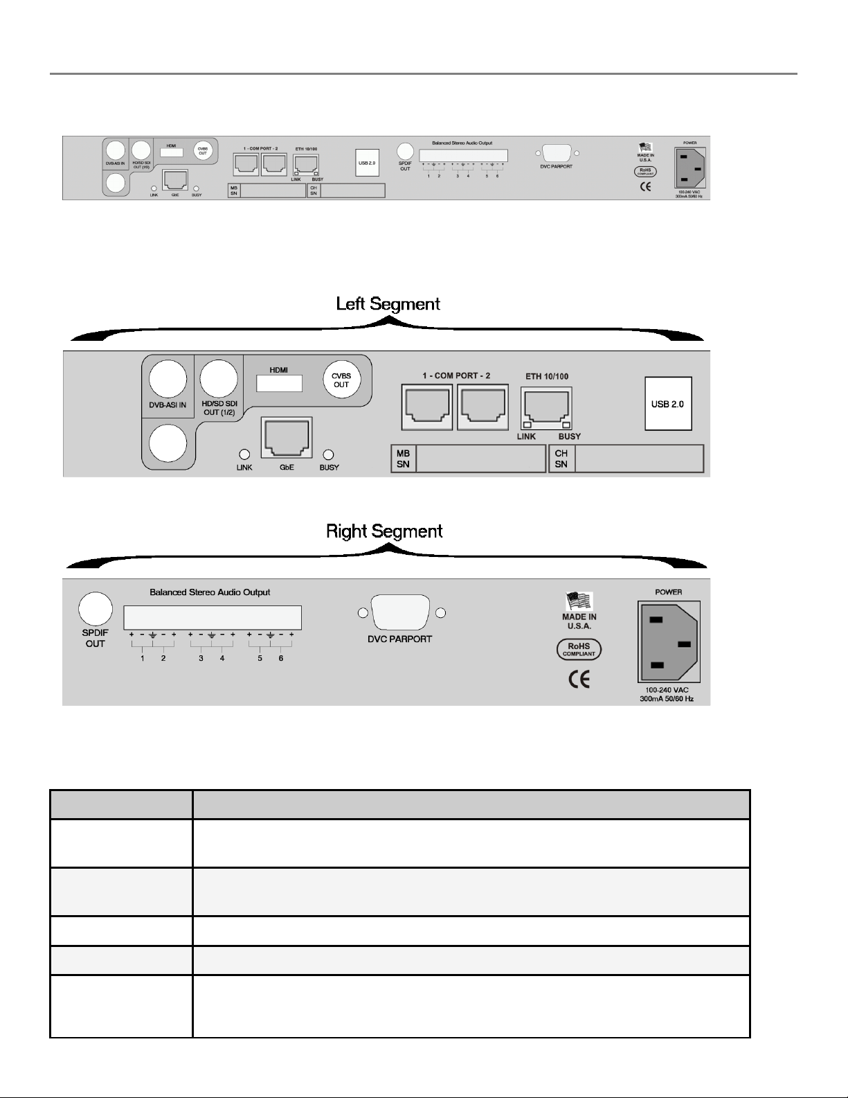
Back Panel Diagram
Note: Some connectors have been discontinued or changed over the life of the product. Consult your units’ rear panel for correct
placement cables and connectors.
Enlarged back panel segments to show connector placement
Connections
Connection Function
DVB-ASI IN Incoming video signals
75 Ohm,terminated SMPTE 259M BNC connector
HD/SD SDI OUT 75 Ohm terminated SMPTE 259M and SMPTE292M (auto-detect) BNC
connector
HDMI HDMI v1.3 and DVI v1.0 compliant transport
CVBS OUT 75 Ohm terminated NTSC or PAL D1 Composite Video Output. BNC connector
GbE (eth1) 10/100/1000 base T ethernet interface; 2 LED indicators
Link- device networked
Busy- traffic on interface
Page 21
COM1 Terminal monitor connection port for diagnostic access to unit's motherboard.
default 115200 bps
COM2 RS232 connection port for API control. default 38400 baud
ETH 10/100
(eth0)
USB 2.0 Not currently supported / Reserved for future use
SPDIF OUT Sony/Phillips Digital Interface; compressed digital audio transport
Balanced Stereo
Audio Out
DVC PARPORT Parallel IO Interface for Start, Stop, Status, Alarm, and general purpose
POWER AC Power- standard 3-pin plug (70-240 VAC 50-60 Hz)
10/100 base T ethernet interface; 2 LED indicators
Link- device networked
Busy- traffic on interface
Six balanced, 600 Ohm outputs on three 5-pin mini-RST connectors
interfacing to control systems
Installation
One Soloist HD Pro server can be installed into a one-rack unit 19” rack slot. Power should be applied to
the unit and configured with a valid IP address and display target via the front panel.
Set-up an IP Address
Step Action
1
2
3
4
5
6
Press the <Mode> button until SYSTEM MENU is displayed on the LCD screen, then
press <Select>.
Press the <Down> arrow until NETWORK MENU is displayed on the LCD screen, then
press <Select>
Press the <Down> arrow until Ethernet IP Address item is shown on the LCD screen.
Enter the IP address desired for the unit using the <Select> and arrow buttons, then
press <Enter> to save.
Note: The Ethernet IP Address and IP Mask are the settings of the Ethernet port used
for control and communication. Make sure that this port is on the same network as the
control computer.
Press the <Down> arrow button until Ethernet IP Mask is displayed on the LCD screen,
then press <Select>.
Enter the IP Mask using the <Select> and arrow buttons, then press <Enter> to save.
Page 22

Set-up a Display Target
Step Action
1
2
3
Press the <Mode> button until DECODER MENU is displayed on the LCD screen, then
press <Select>.
Press the <Down> arrow until Display Target is displayed on the LCD screen.
To change the output display resolution, press <Select> and navigate to the desired
video resolution setting, and then press <Enter> to save.
Note: The display target setting is the output resolution and refresh rate used
simultaneously on both the HDMI, SDI and the composite BNC video outputs.
Therefore, to view video on the composite BNC output port, select one of the NTSC or
PAL display targets.
Make Connections
Connect: Make the following general cable connections for your setup:
Cable Connection
Video Connect a video or Composite monitor to the correct SDI, HDMI or
the composite BNC connector.
Analog Audio Connect Analog Left and Right RCA Cable to display unit
Digital Audio Connect RCA Digital Audio Cable to Digital Audio Decoder
Ethernet Ethernet: Connect an Ethernet cable to the Ethernet port for
external control.
Confirm: Plug in the Adtec Soloist HD Pro and confirm that the IP address is correct on your unit, and
that the Link LED on the front of the unit is lit before using Adtec's web-based control application.
Page 23

Chapter 3 - On-Board Control Interface
Control Application
Adtec Digital provides a web-based command and control (C&C) Graphical User Interface (GUI) application
for our products, often referred to as Web UI. Soloist HD Pro devices with firmware versions 2.05.XX and
up are able to use this application.
Browser Compatibility:
● Firefox ®: 3.0 (recommended) and higher
● MS Internet Explorer®: 7.0 and higher
● Safari®: 3.0 and higher
● Opera®: 9.0 and higher
● Google Chrome®: 31 and higher
Note for Safari® users:
● The C&C program is designed to use the Bonjour Zero Configuration Protocol.
○ When using Safari, click on the " ^^ " symbol to open a networked devices list.
○ Select the device to point the browser to that device's IPA.
○ IE® and Firefox® users can use Bonjour through the use of plug-ins.
* Note to mediaControl Users *
The latest firmware versions on the Adtec Soloist HD Pro Media Player will no longer work with the older
mediaControl interface software.
● mediaControl will not work with firmware versions after 2.3.14.
Zero Configuration Technology
Adtec Digital makes use of Zero Configuration technology to make it easier to integrate your Adtec device into your IP
network. With one mouse click, the device will assign itself an open IP address and announce its presence to the rest of
your network. Adtec devices will reference themselves by serial number, which is also located on the back of the device.
If you wish to access the web application without using Bonjour, and have configured your device with an IP address
manually through the front panel, point a web browser to the device's IP address; the web application sign-in page (see
below) will display.
Page 24
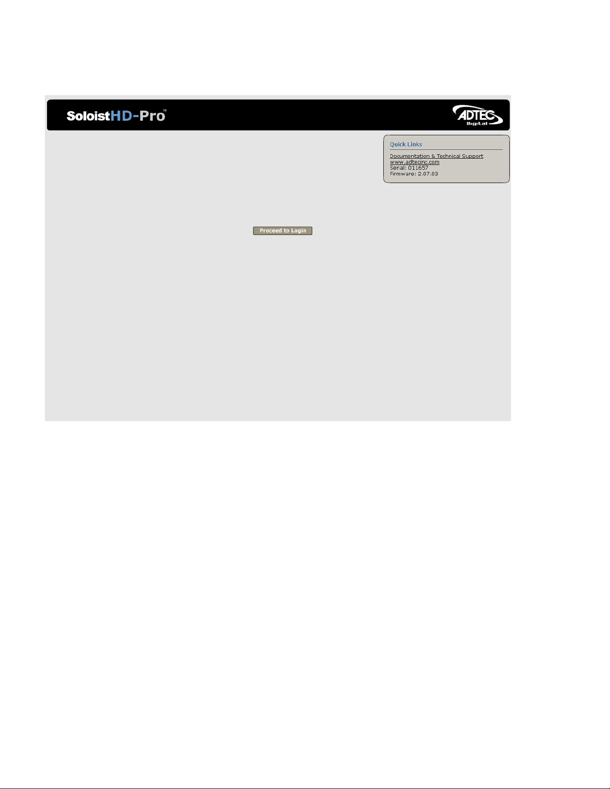
Login
Access the C&C web-based application by pointing your web browser to the unit's IP address. The
following screen (image reduced for clarity) will appear:
Image reduced for clarity
Log in to the Web UI C&C application by clicking the "Proceed to Login" button and typing in the user
name 'adtec' and the password 'none' (the word none spelled out) in the pop-up box that appears. You
can also access release notes from this screen.
Page 25

Control Interface Main Screen
Screen Elements
Firmware Version: the interface application always references the firmware currently running on the
device.
Menu Tabs: the Menu Tabs are used to select various control groups and functions. The Menu Tabs are
explained in other chapters in this manual.
Status Windows: the Status Windows are fixed, and display regardless of which menu has been
selected. The Status Windows provide an "at-a-glance" look at the Playout and Communications activities
of your Adtec Soloist HD Pro player. These same status results can be received by a telnet session or by a
third party controller/monitoring system.
Main Window: the Main Window displays whichever menu has been selected via the Menu Tabs. In the
screenshot above, the Dashboard menu of firmware version 2.07.03 is shown.
Firmware Version: you can also determine your firmware version using an API command during a
Terminal session. Issue the command *.SYSD BAN.
Page 26

Help Notes
Clicking on the Question Mark (?) icon, located next to control terms on all the menu tab pages, will bring
up a pop-up Help Note giving more information about the control and its options. These Help Notes largely
duplicate the information found in this section of the User's Manual.
Dashboard Tab
The Dashboard Tab is where you will control the playout parameters of your media. There are five subtabs accessed from the Dashboard Tab:
● List Builder
● Schedule Builder
● Streaming
● Display
● OSD
List Builder Tab
The List Builder Tab is used to determine and organize the content available to the Soloist HD Pro player.
Image reduced for clarity
The *List Builder* screen has four main parts:
● Virtual VTR controls: virtual buttons for playout, virtual slider control for incremental volume,
audio track selector pull-down.
● Inventory selection: select between all file types, media files, graphic files, or script files.
● Playlists: choose from available user-defined playlists. Playlists are selected by clicking the Playlist
name.
● File window: data on specific files- size, CODEC, file name, etc. Files can be selected by clicking
the file title.
Page 27

Virtual VTR
The controls on the virtual VTR mimic those found on a standard video playback device. The Volume slider
reads out the volume level in decibels for precise control.
For quick reference, the chart below gives the API command for each of the VTR controls.
Graphic Name API Command
Previous file *.DCMD PRV
Stop *.DCMD STP
Play *.DCMD PLY
Pause *.DCMD PAU
Next file *.DCMD NXT
Schedule Builder Tab
The Schedule Builder tab sets playtimes for content with user-selected Schedule Names for ease-ofreference.
Image reduced for clarity
Page 28

Streaming Tab
The Streaming Tab contains controls which determine if the Adtec Soloist HD Pro player is receiving
multicast content, and from where.
Image reduced for clarity
Control Function Options API Command
Program
Number
Audio
Track
identifying number for the program
or event to decode
select the audio track to be
decoded. The "track" is defined as
the first, second, etc. audio track
as found in the transport PGM pid
(transport streams), or as the n'th
audio stream found in a program
stream.
If this control is set to 0, the unit
will look to the Audiostream ID
(AUI) or Input Audio Type (IAT)
settings to detemine which track to
decode. If no option is specified,
the unit will select and decode the
first available audio track.
Drop down selection *.DCMD DPN
0 = track select
inactive
1 - n = track
number
*.DCMD TSN
Page 29

DVB-ASI
Mode
Enable or disable the DVB_ASI
receive operation
OFF
Recieve
*.DCMD DVB
DVB-ASI
Latency
DVB-ASI
Error
Recovery
Multicast
Mode
Multicast
Port
Multicast
IPA
Error
Recovery
Sets the latency delay (in
milliseconds) before the decoder
begins playback from the DVB ASI
source
Sets the timeout value (in
milliseconds) for recovery of DVB
ASI receive after decoder error
condition is detected
turns streaming MPEG to off,
receive, or send; used when unit is
part of a LAN or WAN and is
receiving IP streaming
port number for receiving multicast
on the defined Multicast IP Add.
sets the multicast receive Group IP
address. IP Multicast receiving is
supported from compatible
streamers.
Sets the timeout value (in
milliseconds) for recovery of
multicast receive after decoder
error condition is detected.
text field;
default is 100 (ms)
text field;
default is 100 (ms)
Off
Receive
0-65535 *.DCMD MRP
user-defined
default is 0.0.0.0
text field:
default is 10000
(ms)
range is 33-600000
(ms)
*.DCMD DLT
*.DCMD DER
*.DCMD MMO
*.DCMD MRI
*.DCMD MER
Time Out
(ms)
RTP
(AutoDetect)
Multicast
Connector
sets the timeout value in
millisceonds for return-to-normal
video playback after video
multicast packets are no longer
detected
When on, the system adapts to the
stream received, automatically.
When off, if an RTP stream is
received, the video component will
appear corrupted to the decoder.
Sets the physical connector (on the
rear of the unit) to use for
multicast purposes. Recommended
setting is GigE (10/100/1000)
text field;
default is 300 (ms)
On
Off
Ethernet
GigE
*.DCMD MTU
*.DCMD RAD
*.DCMD MCN
Page 30

Display Tab
The Display tab is used to integrate the Soloist HD Pro with the video display.
Image reduced for clarity
Control Function Options API Command
Start Up Mode determines whether or not the
decoder starts playing
immediately after power-up or reset
with no intervention.
The playback will be from the LIST or
individual spots if no LIST is active
Auto Format display the native format of the
video playing
Display Target the targeted video resolution; set to
match resolution of the intended
display, the decoder scales
automatically; DVI is not active when
SD resolutions are used
On
Off
On
Off
see Supported Video
Targets
*.DCMD STU
NONE
*.DCMD VID
Page 31

Aspect Ratio ratio of horizontal to vertical lines in
the decoded image
Off
AUTO
4x3
16x9
*.DCMD OAR
Blank Mode sets the state of the video output
whenever a unit's
transport is idle or is in transition
Video Position positions the video output on the
display target.
Video Scaling re-sizes the video output. The scale
can be used to reduce the picture
size.
SPDIF Mode compressed or uncompressed audio;
Sony/Phillips Digital Interconnect
Format
Note: Aspect Ratio and Video Scaling/Position cannot be used at the same time. You must choose one or
the other to control the video output.
When Active Format Description is enabled, aspect ratio is forced to OFF.
No Video
Black
Hold
Center
Top Right
Top Left
Bottom Right
Bottom Left
Off
1 - 100% in 1%
increments
Off
Uncompressed
Compressed
Passthrough
*.DCMD BLK
*.DCMD OVS
*.DCMD OVS
*.DCMD SPM
Page 32

OSD Tab
These controls govern the use and appearance of On Screen Display graphics and content.
Image reduced for clarity
Control Function Options API Command
Graphic File select a file for OSD Drop down selection
Select Graphic File from
list by name
Scaling sets scaling and position of
the file to be displayed
Position sets on-screen placement Select Position
Clear OSD Button: clears an existing (loaded and displayed) OSD file from the display
Valid graphic files include JPEG, BMP, GIF and PNG
Off
100% - 1% in 1%
increments
Center
Top Right
Top Left
Bottom Right
Bottom Left
*.DCMD OSD
*.DCMD OSD
*.DCMD OSD
Page 33

Network Tab
Image reduced for clarity
Mirroring
Control Function Options API
Command
Host Mode used to set the ftp mirroring
mode. Mirroring is a
automated ftp process on
Adtec Digital devices
Mirror List
File
file that lists all the files that
the mirror client needs to
download from the
HOSTIPADDRESS. See API
Notes for file format.
Client - Turns mirroring off
MirrorList - Use an
MIRRORLISTFILE to
add/delete local files
MirrorClient - Mirrors all
files found on FTP server
user-defined text field *.SYSD MLF
*.SYSD HOM
Page 34

Host Timer time interval between
mirroring operations. It is
noted in seconds.
text filed;
default is 600 (s)
*.SYSD HOT
Host IP tells the device where to look
for new files
Client
Username
Client
Password
Communications
Control Function Options API Command
XCP sends a system command to
XCP Key sets the XCP Security Key in
the ftp username to be used
during mirroring and other ftp
sessions
the ftp password to be used
during mirroring and other ftp
sessions
a remote client using XCP
protocol or show change XCP
usage
hexadecimal. A value of zero
indicates that the unit will
respond to any XCP
command. A non-zero key
requires a matching XCP key
in the XCP command before
it will respond. The default
value is zero
user-defined;
default is 192.168.10.1
user-defined text field;
default is adtec
user-defined text field;
default is none
Off
On
user-defined text
field;
default is
0x00000000
*.SYSD XCP
*.SYSD XCK
*.SYD HIP
*.SYSD CPW
*.SYSD CPW
Bark sends API commands to
system and redirects output
over network to the BARK
HOST IPADDRESS.
Commands can be packed
together using a colon
Bark Host the IP address to which the
command responses should
be sent via the BARK
Protocol
Bark List the list of commands to be
sent when using BARK
Bark
Interval
Bark Port the port on the receiving
the frequency at which you
want the string of commands
to be sent back to the
designated Bark Host
server that is expecting the
command data from Bark
Off
On
user-defined;
default is
192.168.10.1
user-defined text
field
text field;
default is 514
range is 1025 65535
*.SYSD BARK
*.SYSD BARKLIST HOST
*.SYSD BARKLIST
*.SYSD BARKLIST
INTERVAL
*.SYSD BARKLIST PORT
Page 35

Sync Playback
Control Function Options API Command
Mode feature of Adtec Decoders
that enables multiple Adtec
devices to playback
synchronized
Off
1 - Slave (single)
100 - Master (single)
Additional options
for multiple groups
*.DCMD STC
System Tab
The System Tab gives you control over the unit's functions and integration into the rest of your networked
devices.
Image reduced for clarity
Page 36

Control Function Options API Command
Uptime this readout reports the amount of
time the unit has been running since
the last reset or power-on cycle
Device Name the host name for the unit for
identification and networking
purposes.
When a unit is manufactured, it is
given a name that
combines the product type and the
serial number of the
unit
Gateway
Address
DHCP check box; allows unit to extract it's
Ethernet
Address
(Eth 0)
the IP assignment of the
gateway/router on your network;
limited to one address on Adtec
devices
own IP address, if
switched on, from a DHCP server
IP address of the unit's ControlEthernet (eth0) port
10/100mbps
None (read only) *.SYSD UPT
user-defined text field *.SYSD NAM
text field; valid IP address in
form xxx.xxx.xxx.xxx
checked = On
not checked = Off
text field; valid IP address in
form xxx.xxx.xxx.xxx
*.SYSD GIP
*.SYSD DHC
*.SYSD IPA 0
Subnet Mask
(Eth 0)
GigE Address
(Eth 1)
Subnet Mask
(Eth 1)
NTP Address IP Address of a Network Time
Time Zone designates the time zone the unit is
Date sets the units internal calendar/date
Subnet mask address of the unit's
Control-Ethernet port
IP address of the unit's GigE (eth1)
port 10/100/1000mbps.
Recommended that the GigE Port be
used as a MPEG2 or RTP multicast
receive port
Subnet mask address of the unit's
GigE port
Protocol server
operating in the offset is in hours
from UTC and a Daylight Savings
Setting
function. Visual calendar available
for point-and-click date setting.
text field; valid IP address in
form xxx.xxx.xxx.xxx
text field; valid IP address in
form xxx.xxx.xxx.xxx
text field; valid IP address in
form xxx.xxx.xxx.xxx
text field; valid IP address in
form xxx.xxx.xxx.xxx
text field;
field requires very specific
input to be configured
correctly. Please refer to the
API Note for additional details
text field;
Format: MM/DD/YYYY
*.SYSD IPM 0
*.SYSD IPA 1
*.SYSD IPM 1
*.SYSD NIP
*.SYSD TIZ
*.SYSD TIM
Time sets the unit's internal time clock.
Will auto-populate if unit is
networked to an NTP Server if
enabled.
text field;
24 Hour Clock format:
HH:MM:SS
*.SYSD TIM
Page 37

Power Cycle Button:Clicking the Power Cycle button performs a complete power-down/power-up cycle
on the device. A pop-up warning screen gives you the option of continuing or canceling the action. Cycling
the power to the device will stop all playback; the power-down/power-up cycle takes approximately 45
seconds to complete
Warning Screen:
Upgrade Tab
The Upgrade Tab is used to easily select, upgrade and revert your unit's firmware from the available
versions.
Image reduced for clarity
Procedure:
Installed Versions are firmware versions that have been installed on your device and can be selected as
the current operating version. To select one of these versions, simply click on the <Select> button
associated with the version. Due to the caching properties of your browser, it is necessary to clear your
cache or restart the browser to make sure that the new application pages load.
Page 38

To upload new firmware versions, click on the <Upload> button (located on the top right
side of the window), then click on the <Upload> button on the "Adtec Uploader" pop-up that appears:
Browse your computer for the downloaded firmware file and select the Open or Ok button to begin the
transfer of the firmware to the unit. You should see a status bar progressing to show the current status of
the firmware file being uploaded to the unit. Once the firmware file is loaded onto the unit, you should see
the status bar read “Complete”.
Simulated Image
If the Uploader screen does not load properly, you do not have a compatible version of Java installed. In
this case, use a 3rd party FTP client to transfer the file to the /hd0/media/ folder on the unit. If you FTP
the file to the unit, you will use the same Login user and password you used to access the Web UI. Once
the transfer is complete, it will now be available under the firmware tab.
Further Upgrade instructions can be found referencing the Upgrading Firmware section of this manual.
Page 39

Upgrading from Older Firmware Versions
If your current version is less than v 2.03.13, you will need to use the FTP manual upgrade procedure to
upgrade your unit.
Help Tab
The Help Tab provides another access to Technical Support's contact information, the API Command set,
and the latest Release Notes.
Image reduced for clarity
Page 40

Chapter 4 - How-To Guides
Connecting to the Soloist HD Pro Digital Player
Before you configure your player, you will need to establish a connection.
The default IP for the Soloist HD Pro is 192.168.10.48.
Telnet Connection
To connect to your Soloist HD Pro player using a Telnet connection, attach your Soloist HD Pro to your
local network and launch a telnet session. Logon with the username adtec and password none . Once you
are connected, you can control and monitor the unit by using the API commands. For a complete list of
API commands, point a web browser to the IP Address of your Soloist HD Pro and view the Adtec API
notes.
Serial Connection
To use a serial connection with your Soloist HD Pro, use the terminal kit included with your purchase. This
terminal kit contains a standard ethernet cable and a serial 9 pin adapter, aka “RS232 connector.” Plug
the ethernet cable into the back of your Soloist HD Pro using the port labeled COM2. The other end of the
ethernet cable should be plugged into the 9 pin adaptor. The adapter should then be connected to your
computer via the RS-232 port or with the use of a USB converter cable (not included).
Note: Please note that the use of a USB converter may not always provide connectivity. A setup disk or
drivers from the USB convertor manufacturer may be needed. You can also use a serial connection utility
such as Teraterm or PuTTY.
Page 41

Using TeraTerm
Control Setting
Port The COM port you select in the application window represents
the COM port on your computer that you wish to communicate
from. It is not the COM port number from the back of your
Soloist HD Pro.
Baud Rate The baud rate for COM 2 is 38,400
Data Should be set to 8 bit
Parity Should be set to none
Stop Should be set to 1 bit
Flow Control Should be set to none
Page 42

Using PuTTY
Page 43

Browser-based User Interface
Please note: Adtec's "mediaControl" software is no longer supported and will not work at all with the
newest versions of the Soloist HD Pro firmware.
To connect using the web interface, first use the Front Panel, Serial or Telnet connection instructions given
above to configure the IP Address, Subnet Mask and Gateway IP Address and integrate it into your
network environment.
Note: Microsoft Internet Explorer users may have to open/run the page in “Compatibility View” to perform
some of the functions described in this section.
Connect Using Device Serial Number
If the unit is a brand new unit, you can telnet to the unit using its product-name-serial number. The serial
number in this case is the 6- digit number on the back or bottom of most units. For example:telnet
SoloistHD_Pro-010CEB.local or in your Web Browser Address Bar: http://SoloistHD_Pro-010CEB.local
Using the Web UI
This section will provide information and direction of the use of the on-board Web UI interface that you
can use to upload your own content, create lists and schedules and upgrade or change your firmware
version.
Uploading Content
After you have logged into the unit, you will want to test, playback and schedule your own content files
you have created. This is done from the main window Dashboard Tab under the List Builder sub-tab in the
Web UI. Once on this tab, click the Upload Button in the upper right hand corner of your
window. This will open the Adtec Uploader popup window.
Page 44

Inside of the Adtec Uploader, click the ‘Upload’ Button to browse your computer for files you wish to
upload. Once you navigate to the proper folder on your computer, select the files and select the “Open”
button and your files will begin uploading. When finished, each file will give you a status of complete, then
close out of the Uploader screen, using the ‘X’ at the top right hand of the popup, and your files will be
listed under the inventory on the List Builder tab.
Note: If the Uploader screen does not load properly, you do not have a compatible version of Java
installed. In this case, use a 3rd party FTP client to transfer the file to the /hd0/media/ folder on the unit.
If you FTP the file to the unit, you will use the same Login user and password you used to access the Web
UI.
List Creation
Once you are logged into the on-board Web GUI, under the Dashboard Tab, you will use the List Builder
sub-tab. This is the first page that will be displayed.
Image reduced for clarity
Click the Page Plus Sign (+) next to the Playlists Header (circled in red in the above picture).
You may get a popup notification (will vary depending on web browser and version) that will look similar
to one of these:
Page 45

If so, click it and select to either “Run” , “Temporarily Allow Scripted Windows” or “Activate.
If you received one of the previous popup messages, click the Plus Sign (+) again.
You will be given a new window to create your new list.
This is the name of your list. Add a name and click the OK button. In this example, we are naming the
list ‘Tutorial.’ Note: It is best to avoid any special characters or spaces in the naming of your list to avoid
issues with file location. In place of spaces, you can use dashes (-) or underscores (_).
You will now see your new list under the Playlists header:
Image reduced for clarity
Page 46

Now drag video or image files on the right onto the new list on the left. They will be automatically added
to your list and saved.
Once you have added or completed your new list, click the name of the list, under the Playlists Header, to
check if it is correct or needs to be edited. if you need to change the order, drag a file up or down to the
appropriate place in the list.
Image reduced for clarity
Page 47

When you are satisfied with the list you have created or edited, double click on the name of the list
‘Tutorial.smil.’ You will see the notice “Selected Playlist has been successfully loaded” at the top of
your list and it will also show in the Status Window, on the left side of the screen, under Playback
Settings.
Note: If you make edits to an existing list, you will still need to double click the name of the list to reload /
activate the list.
Image reduced for clarity
To start your new list, click the Stop Button, using the Virtual VTR Controls , and then the Play Button.
Your new list will now be playing.
To delete a list or to remove any of the items from the list, drag the list or the name of the file from the
list to the garbage can at the bottom of the window. Note: The video file is not deleted permanently; it is
only remove it from the list.
Page 48

Schedule Building
Once you are logged into the on-board Web GUI, under the Dashboard Tab, you will use the Schedule
Builder sub-tab. (illustrated image below)
The Schedule Builder Tab will look like this:
Image reduced for clarity
Page 49

Click the Page Plus Sign (+) next to the Schedules Header (circled in red in the above picture). You may
get a popup notification (will vary depending on web browser and version) that will look similar to one of
these:
If so, click it and select to either “Run” , “Temporarily Allow Scripted Windows” or “Activate.
If you received one of the previous popup messages, click the Plus Sign (+) again.
You will be given a new window to create your new schedule.
This is the name of your new schedule. Add a name and click the OK button. In this example, we are
naming the schedule ‘Tutorial.’ Note: It is best to avoid any special characters or spaces in the naming of
your schedule to avoid issues with file location. In place of spaces, you can use dashes (-) or underscores
(_).
You will now see your schedule under the Schedules Header with the letters ‘SCH’ in front of the name.
Image reduced for clarity
Page 50

Now click the green Add Event (+) button. You will get this popup window:
Here you will be able to set the Weekday, Date, Time and type of event you want to schedule the unit to
perform.
Enter the ‘Weekday’ you would like the event to happen. If you want it to happen every day of the week,
leave the field the default ‘-’ (used for a “wild card” for the value).
Optional: Enter the ‘Date’ you would like the event to occur. This is an optional value to be used when
you want the event to only happen on a specific date. Format is month/day/year (MM/DD/YY). If this is
not needed, use the default setting --/--/-- and it will not be used.
Enter the ‘Time” you would like the event to start. Format is hours:minutes:seconds (HH:mm:ss) using a
24 hour clock. You can also use a “wild card” value for some of the values.
Example 1: For a scheduled event to start 30 minutes after every hour, the Time value would need to be
set as: --:30:00
Example 2: For a scheduled event to start at the beginning of every hours, the Time value would need to
be set as: --:00:00
Page 51

Select the ‘Event Type’ you would like to occur at the above defined Weekday/date/time.
CUSTOM: Create a custom event using Adtec API Commands
PLAYLIST: Start a playlist from a previously created list in the List Builder
PLAYSPOT: Play a single video from inventory
MULTICAST RECEIVE: Start receiving an IP Stream, configured using the Streaming Tab
STOP DECODER: Stop playing
MULTICAST OFF: Stop receiving an IP Stream
CLEAR SCHEDULE: Clear the existing schedule and stop it from being active
Once you have created your scheduled event, click the Apply Button from the popup Window. A new line,
containing your event, has been added to your schedule.
Image reduced for clarity
Continue using the Add Event (+) button to add events until your schedule is complete.
If you make a mistake, you can use the Edit Button, next to the event, to make changes to an event.
Page 52

When you are satisfied with the schedule you have created or edited, double click on the name of the
schedule ‘SCHTutorial.dvc.’ You will see the notice “Schedule file
“/media/hd0/dvc/SCHTutorial.dvc” at the top of the Schedule Builder sub-tab. Also, above your
current schedule you will have a notification stating; ‘You are running the schedule SCHTutorial.dvc.’
Image reduced for clarity
Note: If you make edits to an existing schedule, you will still need to double click the name of the
schedule to reload / activate the schedule.
To delete a schedule or to remove any of the events from the schedule, drag the schedule name or the
event from the schedule to the garbage can at the bottom of the window. Note: The video file is not
deleted permanently; it is only remove it from the schedule.
Upgrading Firmware
First, you will need to acquire a new firmware file from Adtec’s Customer Service department or via our
Documentation and Download Site at www . adtedigital . com this file will be a .TGZ file. Note: Make sure
your computer keeps the correct file extension when downloading the file. The file is compressed but you
will not need to uncompress / extract / run / un-zip the file. You will use the file as-is.
Once the file is saved to your computer, you can upload it to your unit using the instructions provided in
the Upgrade Tab section of this user manual.
Page 53

Now that the firmware file has been transferred to the unit, the newly uploaded firmware file will be
located at the bottom of the firmware screen under a new section labeled “Available Firmware
Versions.” (illustrated below)
Image reduced for clarity
Select the Install button associated with the newly uploaded firmware to extract the firmware file and
make the firmware available to be selected on the units’ Installed Firmware Versions list at the top of
the window. You will receive a popup window asking for confirmation. Select Ok on the prompt window.
Once you choose to Install the firmware, you should see a pop-up message indicating the firmware file is
being extracted to the unit. During this time, your units web controller will not be able to be used. You
will see a notice such as this:
Page 54

Once the firmware has completed installing, it will be listed as an “Installed Firmware Version”. To
complete the upgrade, you will use the Select button next to the firmware version in the list.
The unit will give another popup window asking for confirmation and that you will lose connectivity to the
unit. Select the Ok button to continue.
Once the firmware update is in progress, you may receive a popup window stating a “Script Error.” Just
select to stop the script and close the browser.
Before reconnecting to the unit, it is recommended to clear the History / Cache from the browser that you
are using. Once complete, reconnect to the unit and continue with setup, operation or troubleshooting.
If you find that the firmware update / change has had negative effects on your unit or application, you can
change back to a previous or other firmware version in the ‘Installed Firmware Versions’ list by clicking the
Select button next to the desired firmware version. Your unit will reboot into the selected
version. Note: All previous settings, including IP Address, will revert to what they were in the selected
firmware version.
Firmware updates can also be done manually using the Adtec API Command *.SYSD VRN
Page 55

Factory Reset / Restore
At times, it may be desirable to factory restore / default your unit to the original configuration it had when
it was new. On the Upgrade Tab , you will find a list of the currently installed firmware in the ‘Available
Firmware Versions’ list. Your currently installed firmware version will have the distinction of
(***current selection***) to the right of the version number.
Image reduced for clarity
To restore the unit to its’ factory defaulted configuration, click the Restore Button to the
right hand side of the currently selected version. The unit will give another popup window asking for
confirmation and that the unit will reboot. Click Ok to complete the Restore function.
Once the restoration is in progress, you may receive a popup window stating a “Script Error.” Just select
to stop the script and close the browser.
Before reconnecting to the unit, it is recommended to clear the History / Cache from the browser that you
are using. Once complete, reconnect to the unit and continue with setup, operation or troubleshooting.
Playback Prioritization
The Soloist HD Pro will give decode priority to certain configurations over others.
Priority, In order:
1. DVB-ASI Recieve
2. Scheduled Playback
3. IP Mulitcast / Unicast Receive
4. List Playback
This means that a scheduled event will take precedence over playing from a list or decoding an IP Stream.
Page 56

Advanced Use & Scripting
This section elaborates on some advanced uses of the Soloist HD Pro.
Setting up Synchronous Playback
Synchronous playback is a feature of Adtec player decoders that allows multiple decoders to synchronize
content, provided they are on the same network. One unit is designated as 'master', which is tracked
synchronously by units that are designated as 'slaves'. The synchronization is transmitted over an
Ethernet connection using broadcast packets.
How to Use this feature
Using Telnet and API Commands
Step Action
1 For the unit serving as the Master, issue:
*.DCMD STC 100
* CF SAVE
2 For the unit(s) serving as Slaves, issue:
*.DCMD STC 1 (1 Slave) or X for multiple groups (X =
1-9)
* CF SAVE
Operations
All Slave units REPEAT Mode will automatically follow the REPEAT setting of the Master Unit. All Units
(Master and all Slave Units) must have a LIST (even if it's only one clip). All Units (Master and all Slave
Units) must have the same quantity of clips in their lists. All Clips at the same position within the list
(Master and all Slave Units) must be same length.
Clip # Master Slave #1 Slave #2 - X
#1 30 Sec. 30 Sec. 30 Sec.
#2 10 Sec. 10 Sec. 10 Sec.
#3 1 Hour 1 Hour 1 Hour
#4 10 Min. 10 Min. 10 Min.
The generic STC configuration for one set of synchronous devices is 100 for the master and 1 for the
chase units. If more than 1 set of synchronized devices are needed on the same network, they must be
separated by group or channel numbers. There are 9 groups or channels available for up to 9 sets of
synchronous items placed on the same network.
Channel / Group Master STC Setting Slave STC Setting
1 110 10
2 120 20
3 130 30
Page 57

4 140 40
5 150 5
6 160 60
7 170 70
8 180 80
9 190 90
In conjunction with Display Matrix:
Step Action
1 Create your content.
When creating content for synchronous playback to be used with the Display
Matrix, you should be aware of your overall display area. (ex. 2X2, 3X3 or
4X4) .
You should use the dimensions of the overall piece.
If each display is 1920 by 1080 and your overall display is 2 by 2, then the size
of your content would be 3840 by 2160.
This will allow you to use the same piece of content on all four of your screens.
Keep in mind that your final content needs to be included in an MPEG 2
Transport Stream.
2 Once you have your content, upload it to the units and create a lis t .
3 Select one of the units to act as the master and set the other three units as
slaves.
To do this with the on-board Web UI User Interface:
1. connect to the unit.
2. select the Network tab.
3. find the drop-down box for "STC Beacon" and select "Master".
4. repeat this process to create the three Slave units, selecting "Slave".
To do this via Telnet:
1. log into the unit.
2. use the * STC command to configure the unit.
3. See the API documentation provided by pointing a browser to the IPA of the
unit for more details.
4 Set up the Display Matrix to utilize specific sections of the screen.
See the API notes on the * DMX command for additional details.
The overall result is that you have created one piece of content that can be spread proportionally on a
video wall.
Note: Video Files must contain an audio track, even if it is empty, for proper synchronization.
Using Graphic Follows Audio
Graphic Follows Audio or GFA is a feature of the firmware and requires no configuration. It allows for the
display of a specific On-Screen-Display (OSD) Graphic to coincide at the same time and duration as a
specified audio file. The OSD graphic will display in the center of the screen at full resolution
automatically.
Page 58

How to use this feature
Step Action
1 Create your audio file using the audio specifications referenced below as a
guideline.
2 Create your graphic with your display target resolution in mind.
3 Name your audio and graphic file the same name. [ex. myfilename.mp3 ,
myfilename.png ]
4 Load both into your unit and create a list for your audio file (s).
When the list plays and the system prepares to play the audio file, it will look for a
corresponding OSD. If one is found, it will display it. When the audio file ends, the
OSD will be removed.
Audio Standards Guide
Audio Standard Bit Rate Sample
Rate(s) KHz
Dolby Digital AC-3up to 640kbps 32
44.1
48
MPEG 1
MPEG 2 Layer I,
II and III (MP3)
2.0
AAC-LC MPEG-2
MPEG-4
up to:
448kbps (Layer I)
384kbps (Layer II)
320kbps (Layer
III)
max 384kbps 7.35
16
22.05
24
32
44.1
48
8
11.025
12
16
22.05
24,
32,
44.1
48
Notes
Downmix to 2 channel Dolby Pro
Logic
Single channel, dual channel,
joint stereo and stereo modes
Page 59

FTP Mirror Mode
In Mirror Mode, an Adtec device can be configured to mirror content, via FTP, from an FTP server. Adtec
devices that support Mirror Mode can be set to perform one of three roles in a Mirror Mode configuration:
Mode Role
Client unit is serving as a traditional network client- mirroring is off
MirrorList MirrorList mode puts the device in ‘list’ mirroring mode. Only specified
content within a text based list will be downloaded. The list is referred to as
the MLF or MirrorListFile. An MVL file extension is now required for the MLF.
MirrorList is useful for units with smaller storage capacity. They will only
download content within the MLF file
MirrorClient MirrorClient mode puts the device in ‘total’ mirroring mode. It will download
all content hosted on an FTP server with the given credentials to
it’s /hd0/media/ folder, including SHD, SMIL, and DVC files
Configurations
MirrorClient
Name Specification API Command
Host Mode The FTP mode of the unit,
client/mirrorclient/mirrorlist
Host IP Address The FTP Server to mirror content from *.SYSD HIP x.x.x.x
Host Timer Time, in seconds, to wait until next server
login
Client Username
Password
FTP Client Pasv. Changes between Active and Passive
FTP Time Out Maximum time in seconds that the FTP
FTP Data Time Out Maximum time that client waits on
Username and Password to login to FTP
Server
Mode. Default is Passive
Client waits for a response from remote
system, default = 4 seconds
inactivity from remote system during file
transfer, default = 45 seconds
*.SYSD HOM mirrorclient
(where x.x.x.x is the IP
address of the external
server)
*.SYSD HOT xxx
[where xxx is time in
seconds, default = 600
(10 minutes)]
*.SYSD CPW
username,password
*.SYSD FPA passive
*.SYSD FTO 4
*.SYSD FDO 45
No Not Replace MPEG This allows the mirroring mode to not
replace content even if it already exists on
the unit and the date on the server is
newer; default = no. NO will replace items
when the time/date stamp is different on
the server.
*.SYSD DNR no
Page 60

Mirror List
All MirrorClient configurations are valid for MirrorList, with one additional configuration being available:
Name Specifications API Command
Mirror List
File
A basic MirrorList looks similar to this:
Execution Logic
FTP Download logic follows this progression:
1. Host Timer Expires.
2. Login to FTP Server.
3. Perform directory listing with date/time stamp of files.
4. Check against MirrorListFile and hard drive.
5. If file does not exist on hard drive, download.
6. If file does exist on hard drive, check time/date of both files- if time different and DNR = NO,
then download.
7. Delete specific files in delete section if found.
A file that lists all content that needs to be
downloaded from Host IP Address.
*.SYSD MLF
MasterContent.MVL
API Commands used in Mirror Mode
To view detailed descriptions of Adtec API commands, point a web browser to the IP address of your
device. Once logged in, click on the API Notes link located on the Help Tab .
The basic command set used in Mirroring:
● HOSTTIMER
● HOSTIPADDRESS
● MIRRORLISTFILE
● CLTUSERPASSWORD
● FTPTIMEOUT
● FTPDATATIMEOUT
● DONOTREPLACEMPEG
● FTPCLIENTPASV
Notes:
● In MirrorList mode, the MIRRORLISTFILE is always downloaded first.
● A change to a Mirror Mode (MirrorList or MirrorClient) will change configuration, but mirroring will
wait until HOSTTIMER expires before executing the desired hostmode.
● On newer generation Adtec products, "client" mode still allows the FTP server to run (this is
different from legacy Adtec products such as edje1013).
Page 61

● Because mirroring is performed based on date/time, Adtec Digital recommends keeping all third
party encoders, servers, and Adtec units synchronized to a time server.
○ Synchronized time helps with management of content and basic content troubleshooting.
● A drive space management system is based on HOSTMODE that will detect when there is about
200MB of free space and remove files until there is 300MB of free space.
○ In MirrorList mode, files not in the list, but present on the system will be deleted to meet
300MB.
○ In MirrorClient mode, the oldest files found on the system will be removed to meet 300MB.
○ Drive space is not checked in Client Mode.
● MVL Files recognize the #UNITS_NAMED directive as in DVC files, as well as
#MVL_DELETE_FILES_ON.
Using an NTP Server
Network Time Protocol (NTP) is used to synchronize the system clocks of networked devices to Universal
Time through the use of a timestamp packet sent through the UDP port 123 transport layer. NTP features
an integral jitter buffer which aids in ensuring continuous video and audio playout.
● Synching your Adtec device to an NTP server can provide:
○ Scheduled Events trigger at the proper time.
○ Logging is logged with the proper date/time stamp which provides easier
troubleshooting/viewing of logs
● Adtec Digital recommends that the unit's time be the same for STC setups.
○ Generally, STC doesn't use the system time clock; instead, it uses the STC Time Stamp
Index of the MPEG file.
Set-up an NTP Server
If you will be doing scheduled playback of content, it is highly recommended to configure for an NTP
network time server as follows:
Using the Front Panel:
Step Action
1 Press the <Mode> button until SYSTEM MENU is displayed on the LCD screen,
then press <Select>.
2 Press the <Down> arrow until NTP MENU is displayed on the LCD screen, then
press <Select>.
3 Press the <Down> arrow until NTP Server IPA is displayed on the LCD screen.
4 Enter the IP address of the NTP server using the <Select> and arrow buttons,
then press <Enter> to save.
Note: Entering 0.0.0.0 as the IPA will cause the server to synchronize with its
own time.
An NTP Server can also be configured using the on-board Web UI under the System Tab .
Page 62

Guide to using DVC Files
Digital Video Command (DVC) Files are text files that can be placed within the storage medium of an
Adtec unit to allow a user to run Lists, Schedules, API Commands, or Parallel port configurations. The files
can be placed in storage to be recalled later or set to automatically execute upon power up of the unit.
The "RUN" API command is used to execute DVC files. The RUN command uses the command handler
SYSD and has five options and six executable arguments available.
Command Format:
*.SYSD RUN [option code] [argument ]
Options:
Code Function
D Debug output
I do not initialize; relevant to "LST" and "SCH" files only
F do not finalize; relevant to "LST" and "SCH" files only
M Add using multiples; relevant to "LST" files only
C always evaluate initialize directive; used for wildcard UNITS_NAMED mode
Note: in the table below, "xxxx" is the filename being executed.
Code Function
file name placeholders and wildcards vaild
CMDxxxx.DVC a series of commands which execute sequentially as
if typed at the command prompt manually
SCHxxxx.DVC a list of "rules" or scheduled events, which have the general
form of <time> <command>. When the current time satisfies a
rule in the schedule, the command is executed
LSTxxxx.DVC a series of media filenames which play sequentially, also can
be thought of as a ‘playlist’ of media content
PARxxxx.DVC maps certain commands to be executed when certain pins are
shorted on the parallel port, a parallel port configuration file
any smil file
name
Quick Notes:
1. DVC files that end with AUTO, boot at startup, ex: CMDAUTO.DVC.
2. The first 3 characters of a DVC file specify the type.
3. DVC files can be run from the boot process, scheduler, external controller, parallel port and/or manually
via serial/network.
4. The last line of all Adtec DVC files must contain a carriage return <enter>.
Page 63

Troubleshooting:
1. Spaces are not permitted in DVC media file names without delimiters. Please use “quotes” around
media file names that contain spaces. Spaces are generally not recommended in file names, but
can be used.
2. Some text editors will automatically add a .TXT extension to a newly created file. Make certain that
this does not happen.
3. Two forward slashes ‘//’ or a single pound sign ‘#’ can be used as comments in DVC files. Be
careful not to place comments at the beginning of PAR files.
SHD Files - A Shadow file is a text file stored on an Adtec unit’s storage medium that contains a list of
System Time Clicks (tics) followed by a command. The commands will execute at the specific time (tics)
within the playing of a specific media file. Form- <MEDIA
FILE NAME>.SHD
MVL Files – An MVL file is a Mirror List file (MLF) that contains a list of files to be mirrored from an ftp
server. MLF is brought over from our legacy products, but the file itself is now recommended to use an
MVL extension instead of MLF or TXT.
SMIL Files – smil is a newer format for creating playlist files for Adtec players that are based upon the
smil XML standard. The smil format can be very powerful, but at this time the players utilize them in a
basic way. SMIL Files are required for LIST LOAD operations. They will allow smoother starts compared to
LST.DVC files because LST.DVC files will run immediately when called regardless of what the player is
doing. If a smil file is loaded, the first spot of the list is played when the currently playing file is finished.
List loads can end up
looking smoother to the end user (depending upon use) due to the noninterruptive behavior.
CMDxxxx.DVC Files
Command DVC files are text files that contain a series of commands which execute sequentially as if typed
at the command prompt manually. These types of files are commonly used for easy configuration of
multiple units or to change configurations on the fly.
An example CMDAUTO.DVC file that runs on bootup may look like the following:
This file will change the repeat setting, configure the video output to 720P60 and configures the startup
option.
Page 64

SCHxxxx.DVC Files
Schedule DVC files are text files that contain times and dates to run a specific command. These are most
commonly used for timed video playback.
The format of strings within the SCH file are:
dd MM/DD/YY HH:MM:SS <COMMAND>
Where:
dd = day of the week, MO (Monday), TU, WE, TH, FR, SA, SU.
MM = 2 digit Month from 01 to 12.
DD = 2 digit day from 01 to 31.
YY = 2 digit year from 00 to 99.
HH = 2 digit hour 00 to 23 (24 Hour military time)
MM = 2 digit minute from 00 to 59
SS = 2 digit second from 00 to 59
<Command> = The command you want to issue at the given time
Schedules also have the capability of using WILDCARDS (--) meaning that all fields do not need to be
filled in. For example:
If the user intends to run a file at 8:00AM every Monday, their schedule line would show the following:
MO --/--/-- 08:00:00 *.dcmd ps myfile.mpg
If the file needed to be played every day it would show
-- --/--/-- 08:00:00 *.dcmd ps myfile.mpg
Or if it needed to play only on the first of the month it would show
-- --/01/-- 08:00:00 *.dcmd ps myfile.mpg
A sample schedule that runs a list each day at 8:00AM and stops at 7:45PM (19:45) may
look like this.
Quick Notes: The difference between RUN and LST LOAD when using lists. LST LOAD does not work with
DVC files. RUN does not work with LST .smil files.
Page 65

LSTxxxDVC Files
List DVC files are text files that contain a list of media files to play in a sequential order.
A sample play list with video, music, and pictures may look like the following.
When the following file is loaded onto the player it can be instantly loaded and played by issuing a *.sysd
RUN LSTAUTO.DVC command or by resetting the box. The RUN command will load a DVC list into memory
and play it immediately.
PARxxxx.DVC Files
Par DVC Files are text files that configure the data inputs of the parallel port. The ‘Parallel Port’ section
contains more hardware information on the parallel port.
A sample PAR file may look like the following:
The first letter of the file must be a B for bitmode (4 inputs) or M for multplex mode for muxmode (15
inputs, 16 data bits) utilized with an Adtec PARMUX board.
Each row afterwards is for each data bit, D0 – D3 where D0 = Pin 5, D1 = Pin 4, D2 = Pin 3, and D3 = Pin
2. Each state is separated by open and closed brackets ‘[‘ ‘]’ that will contain an API command to run. The
states are low, rising, high, and falling respectively as seen in the next section.
The rising edge is the most common state to put commands in. A combination of rising and falling can be
used for latching contact closures. A non-usable text sample of the rows and columns.
PIN / BIT LOW RISING HIGH FALLING
5 / D0 [ ] [ ] [ ] [ ]
4 / D1 [ ] [ ] [ ] [ ]
3 / D2 [ ] [ ] [ ] [ ]
2 / D3 [ ] [ ] [ ] [ ]
Page 66

The PARAUTO.DVC file above will play a file when Pin 4 is closed or gets +5VDC. It will run a command file
when Pin 3 is closed. Pin 5 and 2 are disabled, they will have no effect when +5VDC is applied. Disabling
pins is sometimes useful once a file starts to keep a user from pressing the button again thus interrupting
a possible show. PAR files with blank commands can be used to disable all inputs until the next PAR is
loaded.
Troubleshooting:
1. PARTEST can be used to simulate functionality. See the API for more details.
2. PARDUMP is a legacy command brought over which shows parallel changes via Serial. This
command may not be implemented in some firmware versions.
3. PARMUX Board documentation, for details on 15 data inputs, can be found by contacting Adtec
Support for additional details.
Shadow Files (xxxx.SHD Files)
A shadow file is a text file that will execute an API command at a specific time while a specific file is
playing. The time format used is tics, while a tic in relation to seconds is 90,000 (ninety thousand) tics per
second. The name of the shadow file determines which video file will run it. For example, if the video is
named ‘myvideo.mpg’, the shadow file will be loaded when myvideo.mpg plays if the name of the shadow
is ‘myvideo.SHD’. The command will then execute after the said amount of tics have passed.
Shadow files are commonly used to trigger events during playback of a specific spot, such as trigger an
external device via RS232, load a new playlist, or display an OSD.
A Shadow file may look like the following:
This example would send an RS232 ASCII string ‘CUESWITCH’ from the serial port 3 seconds (90,000 * 3)
into playback of myvideo.mpg. At 120 seconds into playback (90,000 * 120), the next list will be loaded IF
THE FILE IS AT LEAST 120 SECONDS.
Troubleshooting:
1. The API command to turn Shadow recognition on is SHADOW/SHD. ‘*.dcmd shd on’, always
remember to ‘*.dcmd cfg save’. Shadow is turned off by default.
2. Shadow files can be placed in /hd0/shd/
3. There are 90,000 Tics Per Second., The first line of tic and command in the file must be greater
than 4500.
Page 67

Video Connector Compatibility
Reference
With the wide variety of display targets supported by modern video decoders, and the multitude of video
monitors that can be used, it can be challenging to match a display target to compatible type of video
input connector. Adtec Digital has created this reference to make it easier to match video monitors and
their input connectors to compatible display target settings in our products, in order to get the best
performance out of your Adtec Digital device.
Here are some common rules regarding the matching of your video input connector with the display
targets it supports:
● Video display targets must be selected based on the monitor type that will display them. In this
reference, we list out the display targets specific to televisions and PC monitors.
● Display targets must also be matched to the connector type.
● DVI connections support both television standards and PC monitor standards.
○ If you are using a DVI connector, match the display target to the monitor type.
● Newer LCD and plasma monitors may support both television standards and PC monitor standards.
● If you are using an LCD or plasma monitor, match the display target to the connection type.
○ Use PC monitor standard display targets for VGA connections
○ Use TV standard display targets for other connections.
● If you are using a converter/adaptor cable (for example converting HDMI to DVI), the connector to
consider is the one that plugs into the monitor- that connector must determine the display target
used
Television Standards
If you are connecting your device to a television or monitor that supports television standards, you should
use one of the following connections and display targets.
Connector
on Adtec
Device
Composite
(BNC
or RCA)
DVI
Single Link
HDMI (Soloist
HD Pro,
mediaHUB HD
Pro and
mediaHUB-HD
422 Only)
Connector
on Display
Composite
(BNC or
RCA)
HDMI Digital YCrCb or
HDMI Digital YCrCb or
Signal Colorspace Image Notes
Analog YCrCb Provides only video. For
RGB
RGB
audio, use separate
SPDIF, RCA (l /r) or
unbalanced audio cable
depending on the Adtec
Device
Provides only video. For
audio, use separate
SPDIF, RCA (l/r) or
unblanced audio cable
depending on the Adtec
Device
Provides audio
and video
Page 68

A complete list of recommended and supported video resolutions can be found in Chapter 2 under the
Display Target section.
Troubleshooting Guide
Issue Cause
The video displays but appears shaded in
magenta or green.
No video is displayed or the monitor reports
that it has 'no sync' or 'out of range'
The video is displayed but does not fill the
entire screen, there may be black bars on
the top and bottom or on the sides
The colorspace of the selected display
target does not match the monitor and/or
connection type used. Either switch your
video display target or switch your
connector.
Possibility 1: The wrong input is selected on
your monitor.
Possibility 2: A display target has been
chosen that is not supported by your
monitor.
Possibility 1: The view mode of the monitor
is set incorrectly (full-screen, stretch, dotfor-dot, through, etc.)
Possibility 2: The monitor input being used
is expecting a different resolution (aspect
ratio) than the selected display target is
providing
Page 69

Chapter 5 - Appendix
Appendix A - GNU General Public License
Version 2, June 1991 Copyright (C) 1989, 1991 Free Software Foundation, Inc.
59 Temple Place, Suite 330, Boston, MA 02111-1307 USA
Everyone is permitted to copy and distribute verbatim copies of this license document, but changing it is
not allowed.
Preamble
The licenses for most software are designed to take away your freedom to share and change it. By
contrast, the GNU General Public License is intended to guarantee your freedom to share and change free
software--to make sure the software is free for all its users. This General Public License applies to most of
the Free Software Foundation's software and to any other program whose authors commit to using it.
(Some other Free Software Foundation software is covered by the GNU Library General Public License
instead.) You can apply it to your programs, too.
When we speak of free software, we are referring to freedom, not price. Our General Public Licenses are
designed to make sure that you have the freedom to distribute copies of free software (and charge for this
service if you wish), that you receive source code or can get it if you want it, that you can change the
software or use pieces of it in new free programs; and that you know you can do these things.
To protect your rights, we need to make restrictions that forbid anyone to deny you these rights or to ask
you to surrender the rights. These restrictions translate to certain responsibilities for you if you distribute
copies of the software, or if you modify it.
For example, if you distribute copies of such a program, whether gratis or for a fee, you must give the
recipients all the rights that you have. You must make sure that they, too, receive or can get the source
code. And you must show them these terms so they know their rights.
We protect your rights with two steps: (1) copyright the software, and (2) offer you this license which
gives you legal permission to copy, distribute and/or modify the software.
Also, for each author's protection and ours, we want to make certain that everyone understands that there
is no warranty for this free software. If the software is modified by someone else and passed on, we want
its recipients to know that what they have is not the original, so that any problems introduced by others
will not reflect on the original authors' reputations.
Finally, any free program is threatened constantly by software patents. We wish to avoid the danger that
redistributors of a free program will individually obtain patent licenses, in effect making the program
proprietary. To prevent this, we have made it clear that any patent must be licensed for everyone's free
use or not licensed at all.
The precise terms and conditions for copying, distribution and modification follow.
GNU GENERAL PUBLIC LICENSE TERMS AND CONDITIONS FOR COPYING, DISTRIBUTION AND
MODIFICATION
0. This License applies to any program or other work which contains a notice placed by the copyright
holder saying it may be distributed under the terms of this General Public License. The "Program", below,
refers to any such program or work, and a "work based on the Program" means either the Program or any
derivative work under copyright law: that is to say, a work containing the Program or a portion of it, either
verbatim or with modifications and/or translated into another language. (Hereinafter, translation is
included without limitation in the term "modification".) Each licensee is addressed as "you". Activities
other than copying, distribution and modification are not covered by this License; they are outside its
scope. The act of running the Program is not restricted, and the output from the Program is covered only
if its contents constitute a work based on the Program (independent of having been made by running the
Program). Whether that is true depends on what the Program does.
1. You may copy and distribute verbatim copies of the Program's source code as you receive it, in any
medium, provided that you conspicuously and appropriately publish on each copy an appropriate copyright
Page 70

notice and disclaimer of warranty; keep intact all the notices that refer to this License and to the absence
of any warranty; and give any other recipients of the Program a copy of this License along with the
Program. You may charge a fee for the physical act of transferring a copy, and you may at your option
offer warranty protection in exchange for a fee.
2. You may modify your copy or copies of the Program or any portion of it, thus forming a work based on
the Program, and copy and distribute such modifications or work under the terms of Section 1 above,
provided that you also meet all of these conditions:
a) You must cause the modified files to carry prominent notices stating that you changed the files and the
date of any change.
b) You must cause any work that you distribute or publish, that in whole or in part contains or is derived
from the Program or any part thereof, to be licensed as a whole at no charge to all third parties under the
terms of this License.
c) If the modified program normally reads commands interactively when run, you must cause it, when
started running for such interactive use in the most ordinary way, to print or display an announcement
including an appropriate copyright notice and a notice that there is no warranty (or else, saying that you
provide a warranty) and that users may redistribute the program under these conditions, and telling the
user how to view a copy of this License. (Exception: if the Program itself is interactive but does not
normally print such an announcement, your work based on the Program is not required to print an
announcement.)
These requirements apply to the modified work as a whole. If identifiable sections of that work are not
derived from the Program, and can be reasonably considered independent and separate works in
themselves, then this License, and its terms, do not apply to those sections when you distribute them as
separate works. But when you distribute the same sections as part of a whole which is a work based on
the Program, the distribution of the whole must be on the terms of this License, whose permissions for
other licensees extend to the entire whole, and thus to each and every part regardless of who wrote it.
Thus, it is not the intent of this section to claim rights or contest your rights to work written entirely by
you; rather, the intent is to exercise the right to control the distribution of derivative or collective works
based on the Program. In addition, mere aggregation of another work not based on the Program with the
Program (or with a work based on the Program) on a volume of a storage or distribution medium does not
bring the other work under the scope of this License.
3. You may copy and distribute the Program (or a work based on it, under Section 2) in object code or
executable form under the terms of Sections 1 and 2 above provided that you also do one of the
following:
a) Accompany it with the complete corresponding machine-readable source code, which must be
distributed under the terms of Sections 1 and 2 above on a medium customarily used for software
interchange; or,
b) Accompany it with a written offer, valid for at least three years, to give any third party, for a charge no
more than your cost of physically performing source distribution, a complete machine-readable copy of the
corresponding source code, to be distributed under the terms of Sections 1 and 2 above on a medium
customarily used for software interchange; or,
c) Accompany it with the information you received as to the offer to distribute corresponding source code.
(This alternative is allowed only for noncommercial distribution and only if you received the program in
object code or executable form with such an offer, in accord with Subsection b above.)
The source code for a work means the preferred form of the work for making modifications to it. For an
executable work, complete source code means all the source code for all modules it contains, plus any
associated interface definition files, plus the scripts used to control compilation and installation of the
executable. However, as a special exception, the source code distributed need not include anything that is
normally distributed (in either source or binary form) with the major components (compiler, kernel, and so
on) of the operating system on which the executable runs, unless that component itself accompanies the
executable.
Page 71

If distribution of executable or object code is made by offering access to copy from a designated place,
then offering equivalent access to copy the source code from the same place counts as distribution of the
source code, even though third parties are not compelled to copy the source along with the object code.
4. You may not copy, modify, sublicense, or distribute the Program except as expressly provided under
this License. Any attempt otherwise to copy, modify, sublicense or distribute the Program is void, and will
automatically terminate your rights under this License. However, parties who have received copies, or
rights, from you under this License will not have their licenses terminated so long as such parties remain
in full compliance.
5. You are not required to accept this License, since you have not signed it. However, nothing else grants
you permission to modify or distribute the Program or its derivative works. These actions are prohibited by
law if you do not accept this License. Therefore, by modifying or distributing the Program (or any work
based on the Program), you indicate your acceptance of this License to do so, and all its terms and
conditions for copying, distributing or modifying the Program or works based on it.
6. Each time you redistribute the Program (or any work based on the Program), the recipient
automatically receives a license from the original licensor to copy, distribute or modify the Program
subject to these terms and conditions. You may not impose any further restrictions on the recipients'
exercise of the rights granted herein. You are not responsible for enforcing compliance by third parties to
this License.
7. If, as a consequence of a court judgment or allegation of patent infringement or for any other reason
(not limited to patent issues), conditions are imposed on you (whether by court order, agreement or
otherwise) that contradict the conditions of this License, they do not excuse you from the conditions of
this License. If you cannot distribute so as to satisfy simultaneously your obligations under this License
and any other pertinent obligations, then as a consequence you may not distribute the Program at all. For
example, if a patent license would not permit royalty-free redistribution of the Program by all those who
receive copies directly or indirectly through you, then the only way you could satisfy both it and this
License would be to refrain entirely from distribution of the Program. If any portion of this section is held
invalid or unenforceable under any particular circumstance, the balance of the section is intended to apply
and the section as a whole is intended to apply in other circumstances. It is not the purpose of this section
to induce you to infringe any patents or other property right claims or to contest validity of any such
claims; this section has the sole purpose of protecting the integrity of the free software distribution
system, which is implemented by public license practices. Many people have made generous contributions
to the wide range of software distributed through that system in reliance on consistent application of that
system; it is up to the author/donor to decide if he or she is willing to distribute software through any
other system and a licensee cannot impose that choice. This section is intended to make thoroughly clear
what is believed to be a consequence of the rest of this License.
8. If the distribution and/or use of the Program is restricted in certain countries either by patents or by
copyrighted interfaces, the original copyright holder who places the Program under this License may add
an explicit geographical distribution limitation excluding those countries, so that distribution is permitted
only in or among countries not thus excluded. In such case, this License incorporates the limitation as if
written in the body of this License.
9. The Free Software Foundation may publish revised and/or new versions of the General Public License
from time to time. Such new versions will be similar in spirit to the present version, but may differ in
detail to address new problems or concerns. Each version is given a distinguishing version number. If the
Program specifies a version number of this License which applies to it and "any later version", you have
the option of following the terms and conditions either of that version or of any later version published by
the Free Software Foundation. If the Program does not specify a version number of this License, you may
choose any version ever published by the Free Software Foundation.
10. If you wish to incorporate parts of the Program into other free programs whose distribution conditions
are different, write to the author to ask for permission. For software which is copyrighted by the Free
Software Foundation, write to the Free Software Foundation; we sometimes make exceptions for this. Our
Page 72

decision will be guided by the two goals of preserving the free status of all derivatives of our free software
and of promoting the sharing and reuse of software generally.
NO WARRANTY
11. BECAUSE THE PROGRAM IS LICENSED FREE OF CHARGE, THERE IS NO WARRANTY FOR THE
PROGRAM, TO THE EXTENT PERMITTED BY APPLICABLE LAW. EXCEPT WHEN OTHERWISE STATED IN
WRITING THE COPYRIGHT HOLDERS AND/OR OTHER PARTIES PROVIDE THE PROGRAM "AS IS" WITHOUT
WARRANTY OF ANY KIND, EITHER EXPRESSED OR IMPLIED, INCLUDING, BUT NOT LIMITED TO, THE
IMPLIED WARRANTIES OF MERCHANTABILITY AND FITNESS FOR A PARTICULAR PURPOSE. THE ENTIRE
RISK AS TO THE QUALITY AND PERFORMANCE OF THE PROGRAM IS WITH YOU. SHOULD THE PROGRAM
PROVE DEFECTIVE, YOU ASSUME THE COST OF ALL NECESSARY SERVICING, REPAIR OR CORRECTION.
12. IN NO EVENT UNLESS REQUIRED BY APPLICABLE LAW OR AGREED TO IN WRITING WILL ANY
COPYRIGHT HOLDER, OR ANY OTHER PARTY WHO MAY MODIFY AND/OR REDISTRIBUTE THE PROGRAM
AS PERMITTED ABOVE, BE LIABLE TO YOU FOR DAMAGES, INCLUDING ANY GENERAL, SPECIAL,
INCIDENTAL OR CONSEQUENTIAL DAMAGES ARISING OUT OF THE USE OR INABILITY TO USE THE
PROGRAM (INCLUDING BUT NOT LIMITED TO LOSS OF DATA OR DATA BEING RENDERED INACCURATE
OR LOSSES SUSTAINED BY YOU OR THIRD PARTIES OR A FAILURE OF THE PROGRAM TO OPERATE WITH
ANY OTHER PROGRAMS), EVEN IF SUCH HOLDER OR OTHER PARTY HAS BEEN ADVISED OF THE
POSSIBILITY OF SUCH DAMAGES.
END OF TERMS AND CONDITIONS
How to Apply These Terms to Your New Programs
If you develop a new program, and you want it to be of the greatest possible use to the public, the best
way to achieve this is to make it free software which everyone can redistribute and change under these
terms.
To do so, attach the following notices to the program. It is safest to attach them to the start of each
source file to most effectively convey the exclusion of warranty; and each file should have at least the
"copyright" line and a pointer to where the full notice is found.
<one line to give the program's name and a brief idea of what it does.> Copyright (C) <year> <name of
author>
This program is free software; you can redistribute it and/or modify it under the terms of the GNU General
Public License as published by the Free Software Foundation; either version 2 of the License, or (at your
option) any later version.
This program is distributed in the hope that it will be useful, but WITHOUT ANY WARRANTY; without even
the implied warranty of MERCHANTABILITY or FITNESS FOR A PARTICULAR PURPOSE. See the GNU
General Public License for more details.
You should have received a copy of the GNU General Public License along with this program; if not, write
to the Free Software Foundation, Inc., 59 Temple Place, Suite 330, Boston, MA 02111-1307 USA
Also add information on how to contact you by electronic and paper mail.
If the program is interactive, make it output a short notice like this when it starts in an interactive mode:
Gnomovision version 69, Copyright (C) year name of author Gnomovision comes with ABSOLUTELY NO
WARRANTY; for details type `show w'. This is free software, and you are welcome to redistribute it under
certain conditions; type `show c' for details.
The hypothetical commands `show w' and `show c' should show the appropriate parts of the General
Public License. Of course, the commands you use may be called something other than `show w' and
`show c'; they could even be mouse-clicks or menu items--whatever suits your program.
You should also get your employer (if you work as a programmer) or your school, if any, to sign a
"copyright disclaimer" for the program, if necessary. Here is a sample; alter the names:
Yoyodyne, Inc., hereby disclaims all copyright interest in the program `Gnomovision' (which makes
passes at compilers) written by James Hacker. <signature of Ty Coon>, 1 April 1989 Ty Coon, President of
Vice
Page 73

This General Public License does not permit incorporating your program into proprietary programs. If your
program is a subroutine library, you may consider it more useful to permit linking proprietary applications
with the library. If this is what you want to do, use the GNU Library General Public License instead of this
License.
Appendix B - Media Encoding Parameters
When creating content for the Soloist HD Pro, you need so ensure that your encoding parameters match
the decoder for best results.
MPEG 2 Encoding
Creating MPEG2 files, it is recommended to use the following parameters:
Multiplex Type: MPEG2 Transport Stream
Transport Steam composition:
● The file should start with a transport sync byte (0x47) and should maintain packet alignment
throughout the entire duration.
● There should be a minimal amount of fill packets at the start of the file.
● The first non-fill packet should be the PAT packet.
● The next non-fill packet should be the PMT packet(s).
● The next non-fill packet should be the first video stream packet.
● The first video stream packet should contain the following:
■ Adaptation indicator marking the presence of a PCR.
■ The adaptation flag field should have the discontinuity indicator set.
■ Valid PES header with PTS and DTS.
■ Valid video sequence header and GOP header.
● Use the following recommended PID values:
PMT: 0x1e0 (480dec)
PCR: 0x1e1 (481dec, must reference video PID)
Video: 0x1e1 (481dec)
Audio1: 0x1e2 (482dec)
Audio2: 0x1e3 (483dec)
Audio: 192Kbps AC-3 or MPEG Layer 2
HD Content:
● Resolution: High Profile up to 1920x1080 (1080i60 or 1080i50) Note that 1080i60 is not supported
● Bit Rate: 25Mbps constant bit rate (CBR).
SD Content:
● Resolution: Main Profile up to 720x480 NTSC or 720x576 PAL
● Bit Rate: 8Mbps constant bit rate (CBR)
Page 74

MPEG 4.10/AVC/H.264 Encoding
H.264, MPEG-4 Part 10, or AVC, for Advanced Video Coding, is a digital video codec standard which is
noted for achieving very high data compression.
The ITU-T H.264 standard and the ISO/IEC MPEG-4 Part 10 standard (formally, ISO/IEC 14496-10)
are technically identical.
Creating AVC files, it is recommended to use the following parameters:
Multiplex Type: MPEG2 Transport Stream
Transport Stream composition:
● The file should start with a transport sync byte (0x47) and should maintain packet alignment
throughout the entire duration.
● There should be a minimal amount of fill packets at the start of the file.
● The first non-fill packet should be the PAT packet.
● The next non-fill packet should be the PMT packet(s).
● The next non-fill packet should be the first video stream packet.
● The first video stream packet should contain the following:
■ Adaptation indicator marking the presence of a PCR.
■ The adaptation flag field should have the discontinuity indicator set.
■ Valid PES header with PTS and DTS.
■ Valid video sequence header and GOP header.
● Use the following recommended PID values:
PMT: 0x1e0 (480dec)
PCR: 0x1e1 (481dec, must reference video PID)
Video: 0x1e1 (481dec)
Audio1: 0x1e2 (482dec)
Audio2: 0x1e3 (483dec)
Audio: 192Kbps AC-3 or MPEG Layer 2
HD Content:
● Resolution: High Profile up to 1920x1080 (1080i60 or 1080i50) Note that 1080i60 is not supported
● Bit Rate: 25Mbps constant bit rate (CBR)
SD Content:
● Resolution: Main Profile up to 720x480 NTSC or 720x576 PAL
● Bit Rate: 5Mbps constant bit rate (CBR)
NOTE: Content should be padded with a couple black frames front and back for improved visual
transitions between clips.
Page 75

Appendix C - Connector Specifications
The Soloist HD Pro COM1 and COM2 ports are customized RJ45/RJ48 connectors that allow RS232 and
either RS-422 or RS-485. Note that there is no hardware flow control for RS-232 and that RS-485 is
receive only.
The pinout of COM1 and COM2 is:
Pin Use
1 Data Set Ready (DSR)
2 Carrier Detect (DCD)
3 Data Terminal Ready (DTR)
4 Ground (GND)
5 Receive Data (RXD)
6 Transmit Data (TXD)
7 Clear to Send (CTS)
8 Request to Send (RTS)
DB9 to RJ45 Serial Connector Wiring
Page 76

Communications Port Interface Adapter
DB9 Female RJ45 Notes
1 NC No Connect (NC)
2 6 Receive Data (RXD)
3 5 Transmit Data (TXD)
4 1 Data Terminal Ready (DTR)
5 4 Ground (GND)
6 3 Data Set Ready (DSR)
7 7 Request to Send (RTS)
8 8 Clear to Send (CTS)
Appendix D - Technical Specifications
Video
● Video Outputs: One decode configurable to SDI, HDMI, Composite (BNC).
● Sources: ASI, GigE or Internal Hard Drive
● Decode Up and Down conversion SD to and from HD
● Error concealment and de-blocking filter.
● Video aspect format: Auto, 4x3 or 16x9
● Back to back frame accurate playback from same output port.
Standard Definition (SD) Decode
● Maximum bit rate: 15 Mbps
● MPEG2 SD MP@ML, Full D1. NTSC, PAL B, G.
● MPEG4.2 ASP@L5, Full D1. No global motion compensation.
● MPEG4.10 (AVC/H.264) BP@L3 up to 720X480p30 or 720X576p25 resolution, including FMO and
ASO.
High Definition (HD) Decode
● Maximum bit rate: 25 Mbps
● MPEG2 MP@HL up to 1920X1080i60 or 1080i50 resolution.
● MPEG4.10 (AVC/H.264) MP@L4.1 and HP@L4.1 up to 1920X1080p24 or 1080i50 resolution.
Audio
● Audio Outputs: S/PDIF digital audio (RCA female), Analog audio on balanced stereo 5 Pin RST,
HDMI, SDI Embedded stereo audio pair per SMPTE 272M (SD) or SMPTE 299M (HD) based on
target video resolution
● Simultaneous embedding on HDSDI, HDMI and Analog balanced output
Page 77

Audio Decode
● Dolby Digital AC-3: Bit rates up to 640kbps. Sample rates of 32, 44.1 and 48KHz. Downmix to 2
channel Dolby Pro Logic, Multi-channel 5.1 downmix.
● MPEG 1 and MPEG 2 Layer I, II and III (MP3) 2.0: Bit rates up to 448kbps (Layer I), 384kbps
(Layer II) or 320kbps (Layer III). Sample rates of 16, 22.05, 24, 32, 44.1 and 48KHz. Single
channel, dual channel, joint stereo and stereo modes.
● AAC-LC MPEG-2 and MPEG-4:(max 384kbps) Sample rates of 7.35, 8, 11.025, 12, 16, 22.05, 24,
32, 44.1 and 48KHz.
Soloist HD Pro Media Player
● Storage: 750GB internal provides up to 70 hours at 10 Mbps
● Embedded Linux real time operating system.
● Power: 70-240 VAC 50-60Hz and 65 Watts (20 Watts typical)
● Size: 1RU rack mount chassis. 19” wide, 10.5” deep, 1.75” tall
● Weight: 8 lbs.
● Environmental: 0 to 90 Degrees Fahrenheit, Less than 70% RH, Non-Condensing
Communications and Control
● Ethernet 10/100 (RJ-45) Half Duplex, Full Duplex, Auto Negotiate
● GigE 10/100/1000 (RJ-45) Half Duplex, Full Duplex, Auto Negotiate
● Ethernet Protocols: Telnet, FTP, Adtec command API.
● Serial Communications: 2-RS232 (38400-115200 bps, 8, 1 N)
● Embedded Automation: List, Loop, Schedule Logging.
Front Panel
● Keypad: Mode, Select, Enter, Escape, Up, Down, Left, Right
● Blue Translucent LCD (20 characters by 2 rows)
● Host Status LEDs Power, Alarm, Link, Busy, Storage/Aux.
● Decode Operation LEDs Play, Multicast, Video, Audio, Display Target (NTSC, PAL, 720, 1080,
Other), Alarm
 Loading...