


 Loading...
 TA
TA
 3050
3050
10 Port ASI / IP Multiplexer and
Media Router
USER GUIDE |
www.adtecdigital.com |
|
Table of Contents |
|
Product Overview....................................................................................................................................................................... |
1 |
Introduction - About Digital Turn Around........................................................................................................................ |
1 |
Applications............................................................................................................................................................. |
1 |
Benefits of an Adtec Digital Turn Around Router.................................................................................................... |
1 |
About Your Purchase..................................................................................................................................................... |
2 |
Hardware Specification & Requirements................................................................................................................. |
3 |
Front Panel..................................................................................................................................................................... |
3 |
Front Panel Features:.............................................................................................................................................. |
3 |
Back Panel.............................................................................................................................................................. |
3 |
Electrical Device Compliance Notices............................................................................................................................ |
6 |
Safety Warnings and Cautions................................................................................................................................ |
6 |
Lithium Battery Safety Statement............................................................................................................................ |
6 |
Compliance Notices................................................................................................................................................ |
7 |
Getting Started............................................................................................................................................................................ |
9 |
Installation...................................................................................................................................................................... |
9 |
Tour the DTA3050................................................................................................................................................. |
10 |
Front Panel Layout................................................................................................................................................ |
10 |
Back Panel............................................................................................................................................................ |
12 |
Connectivity Features............................................................................................................................................ |
12 |
LED Status Indicators................................................................................................................................................... |
13 |
System Indicators.................................................................................................................................................. |
13 |
Output LEDs.......................................................................................................................................................... |
13 |
Input LEDs............................................................................................................................................................. |
14 |
Setting IP Parameters.................................................................................................................................................. |
15 |
Setting IP Parameters from the Front Panel......................................................................................................... |
15 |
Setting IP Parameters via a terminal (Telnet) session.......................................................................................... |
15 |
Front Panel Programming and Control......................................................................................................................... |
16 |
Modes.................................................................................................................................................................... |
16 |
Front Panel Menu Flows....................................................................................................................................... |
18 |
Pre-programmed Key Sequences......................................................................................................................... |
18 |
Front-Panel-Only Control Options......................................................................................................................... |
19 |
Communications........................................................................................................................................................... |
20 |
LAN....................................................................................................................................................................... |
20 |
RS-232.................................................................................................................................................................. |
20 |
Ethernet................................................................................................................................................................. |
20 |
User Interface............................................................................................................................................................................ |
23 |
Port and Table Mode.................................................................................................................................................... |
23 |
Port Mode.............................................................................................................................................................. |
23 |
Table Mode........................................................................................................................................................... |
23 |
Using the GUI Interface................................................................................................................................................ |
24 |
Introduction............................................................................................................................................................ |
24 |
Signing in to the GUI............................................................................................................................................. |
25 |
System Screen...................................................................................................................................................... |
26 |
Host Screen........................................................................................................................................................... |
27 |
Inputs Screen........................................................................................................................................................ |
29 |
Mappings Screen.................................................................................................................................................. |
31 |
Outputs Screen..................................................................................................................................................... |
33 |
Tables Screen....................................................................................................................................................... |
35 |
Conditional Access Screen................................................................................................................................... |
42 |
IP Destinations Screen.......................................................................................................................................... |
45 |
Multi-Protocol Encapsulation Screen.................................................................................................................... |
49 |
Redundancy Screen.............................................................................................................................................. |
51 |
Encoder Redundancy............................................................................................................................................ |
52 |
Multiplexer Redundancy........................................................................................................................................ |
57 |
Logs Screen.......................................................................................................................................................... |
59 |
Updates Screen..................................................................................................................................................... |
60 |
Modulation Targets Reference.............................................................................................................................. |
62 |
Manual Upgrades.................................................................................................................................................. |
63 |
i
Table of Contents |
|
Operations................................................................................................................................................................................. |
65 |
Manual PID Injection - Overview ................................................................................................................................. |
65 |
Requirements........................................................................................................................................................ |
65 |
Using XCrypt with the DTA3050............................................................................................................................ |
68 |
Appendix.................................................................................................................................................................................... |
71 |
Contacting Customer Support...................................................................................................................................... |
71 |
Telephone and Email Support............................................................................................................................... |
71 |
Information needed for Support............................................................................................................................. |
71 |
Advanced Support Plans....................................................................................................................................... |
72 |
Troubleshooting Guide: DTA3050......................................................................................................................... |
73 |
Technical Specifications for the Adtec DTA30-50-HW3 Digital Turn Around Media Router ...................................... |
74 |
Inputs..................................................................................................................................................................... |
74 |
Outputs.................................................................................................................................................................. |
76 |
DTA Management................................................................................................................................................. |
79 |
Platform................................................................................................................................................................. |
79 |
GNU General Public License........................................................................................................................................ |
80 |
Preamble............................................................................................................................................................... |
80 |
GNU GENERAL PUBLIC LICENSE TERMS AND CONDITIONS FOR COPYING, DISTRIBUTION AND |
|
MODIFICATION............................................................................................................................................. |
80 |
How to Apply These Terms to Your New Programs.............................................................................................. |
82 |
ii
Product Overview
Introduction - About Digital Turn Around
Digital Turn Around (DTA) is a commonly required function for Terrestrial, Cable, and IPTV distribution. Adtec's DTA-3050-HW3 provides the means of receiving up to ten physical Single (SPTS) or Multiple (MPTS) Program Transport Streams and re-multiplexing, table processing, ciphering and routing to a single triplex-mirrored Asynchronous Serial Interface (ASI) and or Gigabit Ethernet (GIGE) interface.
Applications
∙Telco IPTV / Broadband IPTV: Cost-effective and reliable delivery of video, audio and data services to an unlimited number of consumer set top boxes or PC/MAC clients on an IP network.
∙Satellite Digital TV: Aggregate video, audio and data services, process services, inject tables, encrypt and pass them via ASI or IP to modulators supporting traditional DVBS and the emerging DVBS2 or other satellite distribution method.
∙Terrestrial Digital TV: Aggregate video, audio and data services, process services, inject tables, encrypt them and pass them via ASI or IP to modulators supporting ATSC, DVBT, DVBH, DMB, or other terrestrial distribution method.
∙Cable Digital TV: Aggregate video, audio and data services, process services, inject tables, encrypt them and pass them via ASI or IP to modulators supporting traditional DVBC (Annex A, B, C) distribution method.
∙IP over MPEG 2 Transport: Delivery of IP data services to set top boxes or computers over MPEG-2 transport using IP encapsulation.
Benefits of an Adtec Digital Turn Around Router
∙Conditional Access: The DTA-3050 provides DVB-CSA encryption and AES conditional access encrypt and decrypt capabilities. DVB-CSA encryption is available as a Simulcrypt based interfacescompatible with most major DVB-CSA CAS vendors. AES decryption and encryption include support for Verimatrix VCAS for residential set top and computer-based decryption.
∙Aggregation of ASI, SMPTE-310, or IP based SPTS or MPTS services: The DTA-3050 provides ten ASI input ports enabling it to aggregate locally encoded SPTS or re-muxed MPTS from encoders, receivers, video servers or other devices providing MPEG 2 Transport via ASI or IP.
∙IPTV: Gigabit Ethernet distribution of digital television services includes MPTS, SPTS over UDP, RTP for Set Top or computer decoding and MPTS over UDP or RTP for bundled distribution (Digital Simulcast).
∙ASI: An optional 3 port mirrored ASI output interface provides integration with traditional distribution methods including Cable, Satellite, and Terrestrial.
∙SMPTE-310: An optional 2 port mirrored SMPTE-310 output interface provides integration with ATSC distribution.
∙Flexible Configuration & Control: Controlling and configuring the DTA-3050 is easy. Whether using the integrated front panel keypad and LCD, Terminal or remote Web page interface, they respond rapidly and reliably to the desires of the operator.
∙Dynamic EIT Injection: Adtec's free EIT scheduler service DTVGuide comes standard with all DTA products.
1 |
Product Overview |
About Your Purchase
Thank you for purchasing Adtec’s DTA-3050 Digital Media Multiplexer/Router! The DTA-3050 is a revolutionary ASI MPEG 2 Transport Multiplexer and Digital Media Router designed for DVB-ASI distribution applications.
The DTA-3050 represents a revolutionary enhancement for real-time multiplexing applications that require high reliability and broadcast quality without requiring a large budget. The DTA-3050 is capable of providing aggregation of up to ten (10) Single Program Transport Streams (SPTS) or Multiple Program Transport Streams (MPTS) over copper ASI MPEG 2 inputs and producing a Multiple Program Transport Stream (MPTS) output over ASI, SMPTE 310M, or GigE. The DVB-ASI output is targeted to cable and digital satellite television and digital television (DTV) applications over 8VSB (19.39 Mbps) using SMPTE 310M.
All Adtec DTA-3050 Multiplexer/Routers provide table support for MPEG-2 PSI, DVB SI, ATSC PSIP, and DigiCipher II tables. Additionally, they support encapsulation of IP packets via Multi-Protocol Encapsulation (MPE) as defined by ISO/IEC 13818-6 and conditional access: support for the Common Scrambling Algorithm (CSA) using the Ethernet SimulCrypt Interface and Advanced Encryption Standard (AES) with RSA public/private key distribution.
Key features of the Multiplexer/Router include:
∙Highly-Reliable Embedded Design based on Linux Operating System
∙10 copper ASI Inputs
∙Copper ASI Outputs (triple-mirrored outputs)
∙SMPTE 310M (dual-mirrored outputs)
∙PCR Restamping
∙PID Remapping
∙LCD/Keypad display for front panel management and control
∙13818-6 Multiprotocol Encapsulation of Multicast and Unicast IP Data (Optional)
∙SPTS and MPTS to MPTS aggregation
∙DCII Input to DVB feeds
∙PSIP Table Generation
∙Conditional Access
♦Built in DVB Common Scrambler Algorithm (CSA) (Optional)
♦AES encryption for Verimatrix (Optional)
∙Transport Stream over IP
Notices and Disclaimers
(c) 2011 Adtec Digital. All rights reserved. This document may not, in whole or in part, be copied, photocopied, reproduced and translated, or reduced to any electronic medium or machine-readable form without prior consent in writing from Adtec Digital.
Trademarks: DTA305x is a trademark of Adtec Digital. Dolby and the double-D symbol are registered trademarks of Dolby Laboratories. Other product and company names may be trademarks or registered trademarks of their respective companies.
The information in this document is subject to change without notice.
Product Overview |
2 |

Hardware Specification & Requirements
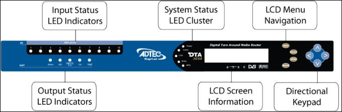
Front Panel
Front Panel
Front Panel Features:
∙8 Button Tactile Raised keypad:
♦Mode, Select, Enter, Escape, Up, Down,Left, Right
∙Blue Translucent LCD
♦20 character by 2 row
∙Front Panel Host LED’s
♦Power, Alarm, Link, Busy, MPE
∙Front Panel LEDs
♦In : 1 - 10 ASI
♦Out : Alarm, ASI, SMPTE 310, CA, GigE
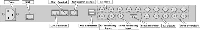
Back Panel
Back Panel Image:
Physical Dimensions
Dimension |
Value |
Heighth |
1.75 inches (44.5mm) |
|
|
Width |
19 inches (483mm) |
Depth |
16 inches (406mm) |
|
|
Footprint |
1 rack unit |
Weight |
13 pounds |
|
|
Power Requirements
∙70-240 VAC switching power supply
∙50/60 Hertz
∙Rated at 94 Watts; return nominal usage 20 Watts
ASI Inputs
∙ASI x 10 (BNC)
∙188 or 204 Byte mode
∙SPTS or MPTS
∙210 Mbps per input
∙256 PIDs per input
∙Input Modes
♦Auto (Remap all services)
♦Manual (Add/Drop/Remap PID/Services)
♦Pass (Pass all services as-is)
♦MHP Injector
♦SI Injector
3 |
Product Overview |
Outputs
·Gigabit Ethernet
¨SPTS over UDP or RTP
¨MPTS over UDP or RTP
¨210 Mbs
¨Very low jitter
·ASI (model is DTA 3050)
¨Mirrored (BNC x 3)
¨Byte or Burst Mode
à54 Mbs Byte
à210 Mbs Burst
¨Jitter less than 150 (nS)
·SMPTE-310 (model is DTA 3051)
¨Mirrored (BNC x 2)
¨Byte Mode only
¨19.39 Mbs fixed
¨SMPTE-310 option includes ASI
Table Processing
·No Tables
·MPEG Tables
¨PAT
¨CAT (if CA is enabled)
¨PMT
·DVB Tables (Add/Drop/Remap DVB Services)
¨NIT
¨SDT
¨TDT/TOT
¨EIT
·ATSC Tables (Add/Drop/Remap ATSC Services)
¨VCT (Cable or Terrestrial)
¨MGT
¨STT
¨RRT
¨EIT (1-4)
·DCII Tables (Add/Drop/Remap Digicypher services to DVB or ATSC)
Conditional Access Encryption
·DVB-Common Scrambling Algorithm (CSA)
·DVB Simulcrypt TS 103 197 v 1.2.1 and SCTE
·OpenCAS TM DVS-278 compliant
·FIPS 140-2 hardware based random number generator (RNG)
·Advanced Encryption Standard (AES)
¨IP Set Top and Computer compatibility
·Approved 3rd Party CA Vendors include:
¨CSA:
àIrdeto
àConax
àEuroCAS
àKeyFly
àXcrypt
¨AES:
àVerimatrix
Host Platform
·PowerPC
·Adtec optimized Linux Kernel
·10/100 Ethernet RJ-45 (Eth 0)
·10/100/1000 Ethernet RJ-45 (Eth 1)
·Serial Port (RJ-48)
·USB 2.0 (2)
Product Overview |
4 |
∙N.C. / N.O. Tally Interface
∙XML Configuration
∙HTTP, FTP, Telnet, IP Logging, DHCP,
♦(XCP Adtec encrypted layer 3 protocol)
Environmental Requirements Operational
Factor |
|
Conditions |
|
Temperature |
|
0 degrees C to +50 degrees C (+32 degrees F to +122 degrees F ) |
|
|
|
|
|
Humidity |
|
5% to 95% (non-condensing) |
|
Cooling |
|
Convection Cooling/Free Airflow |
|
|
|
|
|
Handling/Mounting |
Fixed Use Only |
||
Storage |
|
|
|
|
|
|
|
Factor |
|
Conditions |
|
Temperature |
-30 degrees C to +65 degrees C (-22 degrees F to +149 degrees F) |
|
|
|
|
|
|
Humidity |
5% to 95% (non-condensing) |
|
|
|
|
|
|
Specifications Legal Disclaimer
Note: Specifications subject to change without written notice. Copyright 2008-2010 Adtec Digital. Product and company names may be trademarks or registered trademarks of their respective companies.
5 |
Product Overview |
Intentionally Left Blank

Electrical Device Compliance Notices
Safety Warnings and Cautions
For your safety and the proper operation of the device:
∙This unit must be installed and serviced by suitably qualified personnel only.
∙Disconnect all power before servicing the unit.
∙Do not expose this device to rain or other moisture. Clean only with a dry cloth.
∙If not installed in an equipment rack, install the product securely on a stable surface.
∙Install the product in a protected location where no on can step or trip over the supply cord, and where the supply cord will not be damaged.
∙If a system is installed in a closed or multi-unit rack assembly, the operating ambient temperature of the rack environment may be greater than the room ambient temperature.
∙Consideration should be given to installing the unit in an environment compatible with the maximum recommended ambient temperature of 50 degrees Celcius (122 degrees Fahrenheit).
∙Install the unit in a rack so that the amount of airflow required for safe operation is not compromised.
♦The recommended clearance on the top and sides of the unit is at least ½ “ (one half inch/one centimeter).
∙Mounting of the unit in a rack should be such that no hazardous condition is achieved due to uneven mechanical loading.
∙Use only a grounded electrical outlet when connecting the unit to a power source.
∙Reliable earth grounding of rack-mount equipment should be maintained.
♦Particular attention should be given to supply connection other than direct connections to the branch circuit (e.g., use of power strips).
Lithium Battery Safety Statement
Product Overview |
6 |
Compliance Notices
FCC:
Note: This equipment has been tested and found to comply with the limits for a Class B digital device, pursuant to Part 15 of the FCC Rules. These limits are designed to provide reasonable protection against harmful interference in a residential installation. This equipment generates, uses and can radiate radio frequency energy and, if not installed and used in accordance with the instructions, may cause harmful interference to radio communications. However, there is no guarantee that interference will not occur in a particular installation. If this equipment does cause harmful interference to radio or television reception, which can be determined by turning the equipment off and on, the user is encouraged to try to correct the interference by one or more of the following measures:
∙Reorient or relocate the receiving antenna.
∙Increase the separation between the equipment and receiver.
∙Connect the equipment into an outlet on a circuit different from that to which the receiver is connected.
∙Consult the dealer or an experienced radio/TV technician for help.
Warning: Changes or modifications to this device not expressly approved by Adtec Digital could void the user’s authority to operate the equipment.
Industry Canada:
This Class B digital apparatus meets all requirements of the Canadian Interference Causing Equipment Regulations. Operation is subject to the following two conditions:(1) this device may not cause harmful interference, and (2) this device must accept any interference received, including interference that may cause undesired operation.
Cet appareillage numérique de la classe B répond à toutes les exigences de l'interférence canadienne causant des règlements d'équipement. L'opération est sujette aux deux conditions suivantes: (1) ce dispositif peut ne pas causer l'interférence nocive, et (2) ce dispositif doit accepter n'importe quelle interférence reçue, y compris l'interférence qui peut causer l'opération peu désirée.
European Union EMC Directive conformance statement
This product is in conformity with the protection requirements of EU Council Directive 2004/108/EC on the approximation of the laws of the Member States relating to electromagnetic compatibility. Adtec Digital cannot accept responsibility for any failure to satisfy the protection requirements resulting from a user modification of the product. This product has been tested and found to comply with the limits for Class B Information Technology Equipment according to CISPR 22 / EN 55022.
7 |
Product Overview |
Getting Started
Installation
The DTA-3050 can be installed and made operational in minutes.
1.First, the unit must be installed into a one-rack unit (1U) 19" rack slot, or any secure space where it cannot be easily moved.
2.Power should be applied to the unit and configured with a valid IP address, subnet mask, and default gateway via the front panel via the LCD/Keypad for details on setting the IP parameters via the front panel refer to the procedures in this section.
3.Once the IP parameters have been configured, configuration may take place via the front panel or over the Local Area Network via a Web browser.
4.Select the output type: ASI (default) or SMTPE 310M.
♦If using IP only, please select ASI.
♦When setting the unit up for ASI, a rate must be assigned to the output port before it should be connected to a modulating device.
5.From a PC connected to a LAN, start a Web browser and in the URL box type the IP address configured.
♦Note, if no IP address has been configured, the default IP address can be used (192.168.10.48).
9 |
Getting Started |
Tour the DTA3050
Front Panel Layout
Features and Controls:
Item |
Function |
|
Arrow buttons |
move cursor on the LCD |
|
|
|
|
System Programming Action Buttons |
|
|
Mode programming button |
selects a menu for configuring the unit's operations; 13 available plus 3 |
|
informational "read only" menus |
||
|
||
|
|
|
Select programming button |
chooses a command or field for the router to execute |
|
Enter programming button |
confirms/stores a command and/or data for the router to execute |
|
|
|
|
Escape programming button |
exits a field or moves up to the next menu level |
|
LCD display |
shows selections available or selected for directly programming the router |
|
|
|
Getting Started |
10 |
Item |
|
Function |
|
System Status LED Indicator Cluster |
|
|
|
Power LED indicator |
indicates if power is available to the unit; see LED Indicators for more |
||
information |
|
||
|
|
||
Alarm LED indicator |
indicates if |
a system alarm is in force |
|
|
|
||
Link LED indicator |
indicates if the unit is linked into a network; see LED Indicators for more |
||
information |
|
||
|
|
||
Busy LED indicator |
indicates if |
the unit is receiving or sending traffic; see LED Indicators for more |
|
information |
|
||
|
|
||
|
|
|
|
MPE LED indicator |
indicates if |
multiprotocol encapsualtion is enabled; see LED Indicators for |
|
more information |
|||
|
|||
Input Status LED Indicators |
|
|
|
ASI Input LEDs (10) |
indicates status/function on each of the ten ASI ports; see LED Indicators for |
||
more information |
|||
|
|||
Output Status LED Indicators |
|
|
|
|
|
|
|
Output Alarm LED |
indicates if |
an Output alarm is in force |
|
Output ASI Status LED |
indicates if output is occuring in this mode, and of what level; see LED |
||
Indicators for more information |
|||
|
|||
|
|
||
Output SMPTE 310 Status LED |
indicates if output is occuring in this mode, and of what level; see LED |
||
Indicators for more information |
|||
|
|||
Output CA Status LED |
indicates if Conditional Access is enabled (indicates on/off) |
||
|
|
||
Output GigE Status LED |
not currently used; no functionality. See GigE Indicator on the back panel, |
||
described below. |
|||
|
|||
LCD display |
20-line liquid-crystal display for direct programming of the unit |
||
|
|
|
|
11 |
Getting Started |
Back Panel
Illustration:
Connectivity Features
Connection |
Purpose |
|
Power |
standard 12V A/C electrical power connection |
|
|
|
|
GigE |
used for IP Egress |
|
Terminal Interface |
used to communicate with a PC for serial communications |
|
|
|
|
Fast Ethernet Interface |
management of the DTA-Control GUI |
|
Serial Port |
used to communicate with redundancy switch |
|
|
|
|
USB 2.0 Interface (2) |
for future use (not currently supported in documentation) |
|
ASI Inputs (10) |
Asynchronous Serial Inputs (receive programming) |
|
|
|
|
ASI Redundancy Inputs (2) |
used to link 2 Muxers (DTA3050's) in tandem; one as primary, one as backup |
|
SMPTE Redundancy Input |
used to link 2 Muxers (DTA3050's) in tandem; one as primary, one as backup |
|
|
|
|
Redundancy Tally |
used to hookup an external alarm device |
|
ASI Outputs (3) |
triple-mirrored ASI Outputs |
|
the first two connectors are used for redundant set-ups |
||
|
||
|
|
|
SMPTE 310 Outputs (2) |
mirrored SMPTE Output |
|
the first connector is used for redundant set-ups |
||
|
Getting Started |
12 |
LED Status Indicators
System Indicators
Host Alarm LEDlocated next to the blue LCD display area.
LED Color |
Status |
Red |
Major Alarm |
|
|
Yellow |
Minor Alarm |
Green |
No Alarms |
|
|
Power LEDlocated next to the blue LCD display area.
LED Color |
Status |
Green |
Power to unit |
|
|
Unlit |
No power to unit |
|
|
Link LEDlocated next to the blue LCD display area
LED Color |
Status |
Green |
Link to unit |
|
|
Unlit |
No link to unit |
|
|
Busy LEDlocated next to the blue LCD display area
LED Color |
Status |
Yellow-blinking |
Traffic on unit |
|
|
Unlit |
No traffic on unit |
|
|
MPE LCDlocated next to the blue LCD display area (multiprotocol encapsulation)
LED Color |
Status |
Clear |
No MPE data |
|
|
Yellow |
Enabled; no traffic |
Green |
Enabled; active traffic |
|
|
Output LEDs
Output Alarm LED - located in "Out" indicator group at left of front panel
LED Color |
Status |
Red |
major alarm until cleared or resolved |
|
|
Yellow |
Minor alarm (until cleared or resolved) |
Green |
OKnormal operation |
|
|
13 |
Getting Started |

Output ASI LEDlocated in "Out" indicator group at left of front panel (Asynchronous Serial Interface)
LED Color |
Status |
Red |
no egress; overflow |
|
|
Yellow |
Outputting Fills (only when 100%; do not flash green and yellow) |
Green |
Outputting data |
|
|
Flashing Green |
when unit is configured as the back-up |
|
|
Output SMPTE 310M LEDlocated in "Out" indicator group at left of front panel
LED Color |
Status |
Red |
no egress; overflow |
|
|
Yellow |
Outputting fills |
Green |
Outputting data |
|
|
Clear |
not configured |
|
|
Output CA LED - located in "Out" indicator group at left of front panel (Conditional Access)
LED Color |
Status |
Yellow |
sharing Conditional Access keys |
|
|
Green |
Conditional Access enabled |
Unlit |
Not enabled |
|
|
Output GigE LED
Although there is an LED on the panel, it is non-functional. On the rear panel, a functional GigE indicator is found. See Rear Panel Connections in the "Tour the Box" section for a full description.
Input LEDs
ASI Inputs 1-10
LED Color |
Status |
Red |
no sync/no tables |
|
|
Yellow |
port enabled, but no programs are mapped to output |
Green |
OKnormal operation |
|
|
Green-flashing |
port is a backup in a redundant pair |
|
|
Getting Started |
14 |
Setting IP Parameters
The IP Parameters for the unit can be set from either the Front Panel or through a terminal session. Setting it via the Front Panel is easiest, but both methods are described in this topic.
Setting IP Parameters from the Front Panel
The IP address for the unit can be configured through the front panel by following this procedure:
Step |
Action |
|
1 |
Press "Mode" twice, 'eth0 IP Address' will display in the LCD. |
|
|
|
|
2 |
Press "Select"; the cursor will flash. |
|
3 |
Press the "Right" arrow key to move through the IP Address fields; press the "Up" and "Down" arrow keys to |
|
change the values in those fields. |
||
|
||
|
|
|
4 |
Press "Enter" when all values have been changed. |
|
5 |
Press the "Up" arrow to display 'eth0 IP Mask' on the LCD. |
|
|
|
|
6 |
Press "Select"; the cursor will flash. |
|
7 |
Press the "Right" arrow key to move through the the IP Address fields; press the "Up" and "Down" arrow keys to |
|
change the values in those fields. |
||
|
||
|
|
|
8 |
Press "Enter" when all values have been changed. |
|
9 |
Repeat Steps 1-8 to set the eth1 parameters. |
|
|
|
|
10 |
Press the "Up" arrow to display 'Default Gateway' on the LCD. |
|
'Default Gateway' is the IP Address of your Default Gateway. |
||
|
||
11 |
Press "Select"; the cursor will flash. |
|
|
|
|
12 |
Press the "Right" arrow key to move through the the IP Address fields; press the "Up" and "Down" arrow keys to |
|
change the values in those fields. |
||
|
||
13 |
Press "Enter" when all values have been changed. |
|
|
|
|
14 |
Press "Escape" until the top menu appears again. |
|
|
|
Setting IP Parameters via a terminal (Telnet) session
To set the IP Address via a terminal Telnet session:
Step |
Action |
|
|
1Attach a serial cable between your DTA's terminal interface and the serial communications port on your PC.
2Log onto the PC and pull up a command prompt in the terminal communications window. Set IP address and Subnet Mask.
3-Command: ifconfig eth0 xxx.xxx.xxx.xxx netmask xxx.xxx.xxx.xxx.xxx
-Substitute the hexadecimal values for the IP Address and Subnet Mask to be used.
Set the Default Gateway:
4- Command: route add default gw xxx.xxx.xxx.xxx eth0
- Substitute the hexadecimal values for the Default Gateway to be used.
15 |
Getting Started |
Front Panel Programming and Control
The front panel control group (function buttons, arrow keys, and LCD display) can be used to program and control virtually all aspects of the DTA3050's operations. In fact, there are several commands that can only be carried out through the front panel control group. For more information on these commands, please see the "Front Panel Only Control Options" article.
Modes
The mode button is used to access menus which control the major settings and configurations of the unit.
Mode List
Mode |
|
Purpose |
|
# of |
User |
|
Sub-menus |
Configurable |
|||
|
|
|
|||
Main Menu/Login |
log into unit and control access |
7 |
|
Yes |
|
|
|
|
|
|
|
IP Address |
allows entry of IP addresses for various components |
10 |
|
Yes |
|
Port State 1-10 |
configures the operation of each of the 10 input ports |
8 |
(per port) |
Yes |
|
|
|
|
|
|
|
Output |
cycles output of aggregate signal into SMPTE or ASI |
2 |
|
Yes |
|
Tables |
cycles through table formats |
3 |
|
Yes |
|
|
|
|
|
|
|
IPTV |
input of Global Settings and Mapped Programs |
2 |
|
Yes |
|
Audio Format |
DVB audio settings |
|
1 |
|
Yes |
|
|
|
|
|
|
MPE 1-30 |
configure settings for Multiprotocol Encapsulation |
12 |
|
Yes |
|
DECAP 1-5 |
specifies decapsulization |
4 |
|
Yes |
|
|
|
|
|
|
|
CA1 1-5 |
conditional access configuration |
16 |
|
Yes |
|
ENC RED |
Encoder Redundancy Switch; used to select PESA LNS8 for |
1 |
|
Yes |
|
SWITCH |
redundancy (only supported option) |
|
|||
|
|
|
|||
|
|
|
|
|
|
MUX Redundancy |
Defines whether the unit is designated a Primary or Back-up |
2 |
|
Yes |
|
Mode |
Muxer in a dual-redundancy Mux configuration. |
|
|||
|
|
|
|||
Logs |
none-not supported |
|
n/a |
n/a |
|
|
|
|
|
|
|
H/W Version |
informational only; |
gives the version number of the installed |
|
|
No |
hardware |
|
|
|
||
|
|
|
|
|
|
S/W Version |
informational only; |
gives the version number of the |
|
|
No |
installed on-board GUI |
|
|
|||
|
|
|
|
||
|
|
|
|
|
|
O/S Version |
informational only; |
gives the version number of the |
|
|
No |
installed operating system |
|
|
|||
|
|
|
|
||
Status Mode |
|
|
|
|
|
The front panel can be used to completely configure, operate, and maintain the DTA3050. |
|
|
|
||
When first powered up, the unit will activate in Status Mode.
·Status Mode shows the following operating parameters:
¨operating bit rate.
¨quantity of data ('D' value).
¨quantity of IP data ('V' value).
àIf there is no IP data, an 'F' value will appear, signifying the quantity of fill data.
·By pressing the "Mode" button, each mode menu can be accessed in turn.
·If there is no user activity from the front panel or GUI, the unit automatically shifts to status mode.
¨The default setting for the for this feature is five minutes; however, it can be user-configured for periods between one and nine minutes.
Getting Started |
16 |
Administrator Mode
Important: As of Release v.5, all Adtec DTA3050 units are shipped with auto log-out time set to "None". The unit can be configured by any user without going through a log-in procedure.
To set up an auto-time out:
Step |
Action |
1 |
Press the <Up> arrow twice, until the panel reads "Auto Logout Time". |
|
|
2 |
Press <Select> until the cursor appears on the word "NONE". |
3 |
Use the <left> and <right arrows> to select a time from 1-9 (minutes). |
|
|
4 |
Press <Enter>. |
5 |
<Escape> takes you back to the "Status" menu. |
|
|
Logging In: If you must log back in after being timed out, you must log into the unit from the front panel as an administrative user. The default front panel login password is "USER".
To log in, press the following key sequence:
Step |
Action |
1 |
Press UP arrow |
|
|
2 |
Press SELECT |
3 |
Press ENTER |
|
|
4 |
Press RIGHT arrow |
5 |
Press ENTER |
|
|
Once logged into the unit as an administrative user, the entire suite of configuration possibilities is unlocked for use. Note that changes made in Administrator Mode are not permanent until a "save all" command is executed or until the menu times out and returns to Status mode.
17 |
Getting Started |
Intentionally Left Blank
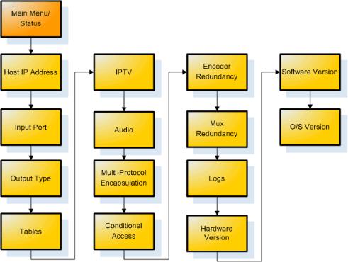
Front Panel Menu Flows
This graphic illustrates the menu flow of the Front Panel in Status and Admin modes:
Pre-programmed Key Sequences
The Adtec DTA3050 has a number of "pre-programmed" shortcut key sequences that can be used to access information about the router or change the contrast on the LCD display, without having to navigate the menu system:
Key Sequence |
Result |
MODE + ESCAPE + DOWN arrow |
LCD Contrast Down |
|
|
MODE + ESCAPE + UP arrow |
LCD Contrast Up |
SELECT + UP arrow |
Firmware version |
|
|
SELECT + DOWN arrow |
FPGA Version |
SELECT + LEFT arrow |
Hardware Version |
|
|
SELECT + RIGHT arrow |
O/S Version |
|
|
Getting Started |
18 |
Front-Panel-Only Control Options
The following Settings and Features are only available from the front panel of the DTA3050there is no GUI support for these features:
1.“Audio Format”.
∙ Set to DVB for audio type 6
∙Set to ATSC for audio type 0x81 2.Transport stream ID “PAT Tran Strm ID” 3.Resetting the unit.
∙Press and hold the "Mode", "Escape", and "Right Arrow" buttons simultaneously, then release them all to affect a reset.
4.MPE routes. 5.Logging
6.“SAP IP address”
7.Backup and Restore configurations. 8.Enable / Disable auto logout.
19 |
Getting Started |
Communications
LAN
The DTA-3050 incorporates two network ports for Ethernet communications over a Local Area Network (LAN) using the Internet Protocol (IP). Command and control over a LAN can be accomplished using a Web browser using HTTP.
RS-232
The DTA-3050 provides an RS-232 interface for an experienced user for advanced troubleshooting. An RJ-45 connector provides a console connection to the DTA-3050, so the unit may be connected directly to a PC’s communications port.
RS-232 Serial Default Parameters
Variable |
Setting |
Baud Rate |
115,200 |
|
|
Data Bits |
8 |
Stop Bit |
1 |
|
|
Parity |
none |
Flow |
none; this is required if you are using Hyper Terminal or some other simple terminal application to |
Control |
communicate with the DTA-3050 via command line. |
|
|
Ethernet
The DTA-3050 provides an Ethernet (10/100BaseT IEEE 802.3u) interface to communicate with the unit over a Local Area Network (LAN). Use of the Ethernet port supports connecting multiple units to a single PC through the use of an Ethernet Concentrator (Hub). The only limitation is the number of ports on the hub and available IP addresses on the network. Point-to-Point Ethernet connection can be achieved with an Ethernet crossover cable. The DTA-3050 also provides a Gigabit Ethernet (10/100/1000) interface for IP Destinations. Both ports can provide web administration.
Caution: both interfaces must be on separate subnets. If both interfaces reside on the same IP network, there will be loss of communication.
Ethernet Default Parameters
Variable |
Setting |
eth0 10/100 |
192.168.10.48 |
|
|
eth0 10/100 subnet mask |
255.255.255.0 |
eth1 GigE IP address |
192.168.20.48 |
|
|
eth1 GigE subnet mask |
255.0.0.0 |
Gateway IP |
0.0.0.0 (defaulted off) |
|
|
User Name |
adtec |
Password |
none |
|
|
Getting Started |
20 |
Intentionally Left Blank
User Interface
Port and Table Mode
This article compares and contrasts Port Mode and Table Mode on the DTA3050 Router. Table Mode and Port Mode are accessed using the "Mode" button on the DTA3050's front panel.
Port Mode
Function |
Explanation |
|
|
All programs and PID’s that are present at the ingress get passed directly to the Egress with no remapping |
|
Pass |
performed. |
|
In this mode, no PID conflict detection is performed on the Egress, so it is the user’s responsibility to ensure |
||
|
||
|
that no conflicts exist. |
|
|
|
|
|
Recommended for most applications. |
|
|
Only programs and PID’s that are manually added by the user are passed to the Egress. |
|
Manual |
PID values and program information are mapped using user-defined values. |
|
|
As a default, the incoming values are used for the outgoing values. |
|
|
In this mode, the DTA does prevent PID conflicts in the Egress as part of the auto-logic algorithm. |
|
|
All programs and PID’s present in the Ingress that are added to the Egress by the user, will be added and |
|
Auto |
remapped by the DTA Router according an auto-logic algorithm. |
|
|
In this mode, the DTA does prevent PID conflicts in the Egress as part of the auto-logic algorithm. |
|
|
|
|
SI Injector |
NIT only |
|
Used for inputting multiple NIT tables and appending them to NIT Other. |
||
|
||
MHP |
Special mode used only for MHP applications. |
|
In this mode, MHP services present in the Ingress can be mapped and associated to services coming in |
||
Injector |
||
through other ports. |
||
|
||
|
|
Table Mode
Table Format |
Explanation |
DVB |
Incoming services are processed using DVB table structure |
|
|
MPEG |
Incoming services are processed using PAT and PMT only |
ATSC |
Incoming services are processed using ATSC table structure |
|
|
DCII |
Incoming services are processed using Digicypher II table structure |
|
Incoming services are processed using information in the manualpidconfigX.xml file (where ‘X’ is |
None |
the port number. |
|
These files are located in the /etc/asimux/ directory |
|
|
23 |
User Interface |
Using the GUI Interface
Introduction
The Adtec DTA3050 features an on-board Graphical User Interface for easy operability.
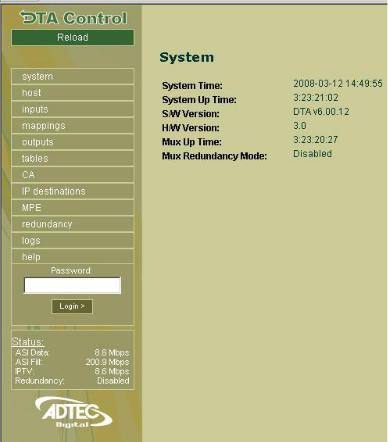
To access the GUI, bring up a web browser, such as Internet Explorer, Netscape Navigator, or Mozilla Firefox, and type your DTA's IP address into the URL locator, and press "Enter". The DTA's on-board GUI will launch, displaying a page like this:
This page lists basic version and operating time information for the unit, and contains a login window. "USER" (in all caps) is the default login password.
Also on this screen (and repeated on every screen) is a Status snapshot window, giving current status for ASI Data, ASI Fill, IPTV, and Redundancy.
The GUI enables you to interface with the DTA3050 through 11 screens. These screens are accessed with the navigation buttons in the left-hand window. These buttons are labelled:
∙System
∙Host
∙Inputs
∙Mappings
∙Outputs
∙Tables
∙CA
∙IP Destinations
∙MPE
∙Redundancy
∙Logs
User Interface |
24 |
Signing in to the GUI
Each screen and its controls are detailed in individual articles which follow. Each screen can be viewed in two ways. If you are signed into the GUI, each screen has editable controls for the configuration of the router's operations. If you view the screen without signing in to the GUI, you see a summary screen of the DTA's current settings, without being able to edit them.
Important: note that signing into the GUI and being signed in from the main control panel are two separate actions.
25 |
User Interface |
Intentionally Left Blank
Loading...