

Page 1

RD-70
10-bit / Multi-CODEC 1080P
Receiver / Decoder
Includes demodulator versions - ADV, LB and PRM
USER GUIDE
02.10.15- v1.02.03
Page 2

Contents
Contents
Trademarks & Copyrights
Electrical Device Compliance Notices
Safety Warnings and Cautions
Compliance Notices
FCC
Industry Canada
European Union EMC Directive Conformance Statement
Chapter 1 - Product Introduction
Covered Equipment
Front Panel
Front Panel LCD
Transport LED Indicators
Audio Decode Indicators
System Indicators
Controls
Reset
Front Panel Menu Structure
Services Menu
RF Rx Menu ( ADV Advanced / PRM Premium )
RF Rx Menu ( LB L - Band )
IP Rx Menu
Video Menu
Audio Menu
VBI Menu
CAS Menu
System Menu
Login
Duration
Com 2
Host Name
Firmware
Feature Menu
Back Panel
DB 9- M Analog audio output pinout
COM 1/ COM 2 to DB 9 Serial Adapter
GPIO and Parport information
GPIO Pinout
Parport Pinout
Chapter 2 - Getting Connected
Introduction to the Control Application
Page 3

Compatible browsers
Ethernet Access
Zero Configuration Access
Login
Firmware Upgrade via Web User Interface
Demodulator Firmware Upgrade via Web User Interface
Upgrading via FTP & Telnet
In Field Feature Upgrades
Permanent Key Instructions
Temporary Key Instructions
Feature Key Descriptions
Chapter 3 - Operational Information
DVB - S / DVB - S 2 AUTO Modes ( ADV and PRM option )
DVB - S / DVB - S 2 AUTO Modes ( LB option )
DVB - S 2 - Recommended use of Pilots
How to use RF Profiles ( LB option )
UDP / RTP / FEC / TCP IP Rx
Multicast Reception - Address
Unicast Reception - Address
Unicast / Multicast Reception
Dolby E , Dolby D , LPCM , and Mpeg 1 Layer 2
AFD - Active Format Description
Genlock System
TS Out Decrypt
Chapter 4 - Appendix
Appendix A - GNU General Public License
Appendix B - Technical Specifications
Base Model ( RD 70- XX )
Inputs
Outputs
Communications
Video and Audio
Physical and Operational
Advanced Demodulator ( ADV option )
L - Band Demodulator ( LB option )
Premium Demodulator ( PRM option )
Appendix C - Adtec Digital Support & Service
Telephone and Email Support
Preparing for Support
SLA Options
Page 4

Trademarks & Copyrights
Copyright: (c) 2011-13 Adtec Digital. All rights reserved. This document may not, in whole
or in part, be copied, photocopied, reproduced and translated, or reduced to any electronic
medium or machine-readable form without prior written consent from Adtec Digital.
Trademarks: RD-70 is a trademark of Adtec Digital. Dolby, Dolby Digital, AC-3 and the
double-D symbol are registered trademarks of Dolby Laboratories. Other product and
company names may be trademarks or registered trademarks of their respective companies.
The information in this document is subject to change without notice.
Page 5

Electrical Device Compliance Notices
Safety Warnings and Cautions
For your safety and the proper operation of the device:
● This unit must be installed and serviced by suitably qualified personnel only.
● Do not break the warranty seals on the device or open the lid. Only approved service
technicians are permitted to service this equipment.
● Disconnect all power before servicing the unit.
● Do not expose this device to rain or other moisture. Clean only with a dry cloth.
● If not installed in an equipment rack, install the product securely on a stable surface.
● Install the product in a protected location where no one can step or trip over the
supply cord, and where the supply cord will not be damaged.
● If a system is installed in a closed or multi-unit rack assembly, the operating ambient
temperature of the rack environment may be greater than the room ambient
temperature.
● Consideration should be given to installing the unit in an environment compatible
with the maximum recommended ambient temperature of 50 degrees Celsius (122
degrees Fahrenheit).
● Install the unit in a rack so that the amount of airflow required for safe operation is
not compromised.
○ The recommended clearance on the top and sides of the unit is at least ½ “
(one half inch/one centimeter).
● Mounting of the unit in a rack should be such that no hazardous condition is achieved
due to uneven mechanical loading.
● Use only a grounded electrical outlet when connecting the unit to a power source.
● Reliable earth grounding of rack-mount equipment should be maintained.
○ Particular attention should be given to supply connection other than direct
connections to the branch circuit (e.g., use of power strips).
Compliance Notices
FCC
Note: This equipment has been tested and found to comply with the limits for a
Class B digital device, pursuant to Part 15 of the FCC Rules. These limits are designed to
provide reasonable protection against harmful interference in a residential installation. This
equipment generates, uses and can radiate radio frequency energy and, if not installed and
used in accordance with the instructions, may cause harmful interference to radio
communications. However, there is no guarantee that interference will not occur in a
particular installation. If this equipment does cause harmful interference to radio or
Page 6

television reception, which can be determined by turning the equipment off and on, the user
is encouraged to try to correct the interference by one or more of the following measures:
● Reorient or relocate the receiving antenna.
● Increase the separation between the equipment and receiver.
● Connect the equipment into an outlet on a circuit different from that to which the
receiver is connected.
● Consult the dealer or an experienced radio/TV technician for help.
Warning: Changes or modifications to this device not expressly approved by Adtec Digital
could void the user’s authority to operate the equipment.
Industry Canada
This Class B digital apparatus meets all requirements of the Canadian Interference
Causing Equipment Regulations. Operation is subject to the following two conditions:(1) this
device may not cause harmful interference, and (2) this device must accept any interference
received, including interference that may cause undesired operation.
Cet appareillage numérique de la classe B répond à toutes les exigences de l'interférence
canadienne causant des règlements d'équipement. L'opération est sujette aux deux
conditions suivantes: (1) ce dispositif peut ne pas causer l'interférence nocive, et (2) ce
dispositif doit accepter n'importe quelle interférence reçue, y compris l'interférence qui peut
causer l'opération peu désirée.
European Union EMC Directive Conformance Statement
This product is in conformity with the protection requirements of EU Council Directive
2004/108/EC on the approximation of the laws of the Member States relating to
electromagnetic compatibility. Adtec Digital cannot accept responsibility for any failure to
satisfy the protection requirements resulting from a user modification of the product. This
product has been tested and found to comply with the limits for Class B Information
Technology Equipment according to CISPR 22 / EN 55022.
Page 7
Chapter 1 - Product Introduction
Covered Equipment
RD-70: 1080P59.94 MPEG 4 10 Bit / MPEG 2 Capable IRD. Transport Stream inputs
standard on ALL RD models include ASI and GigE. Video outputs standard on ALL models
include SD/HD/3G-SDI (x4, one output is SFP/Optical), Composite, and Digital Video.
Standard audio decode includes four (4) Dolby E pass-through and four (4) stereo pairs (8
mono) of MPEG 1 Layer 2 with an optional upper 4 stereo pairs (8 stereo pairs or 16 mono
channels). BISS 1 / E decryption included. Includes Genlock & Redundant AC power supplies.
Optional DVBS/S2 demodulator are packages available.
RD-70 w/ Advanced Demodulator (RD70-XX-ADV): RD70 (as configured above) +
Advanced Demodulator which adds Advanced Newtec Demodulator. Supports L-Band, DVBS 1 - 30 Mbaud, DVB-S2 1 - 30 Mbaud.
* Software Key field upgradeable to 16APSK.
RD-70 w/ 01 L-Band Demodulator (RD70-XX-LB): RD70 (as configured above) +
Advanced Demodulator which adds 01 L-Band Demodulator. Supports L-Band, DVB-S 1 - 62
Mbaud, DVB-S2 1 - 65 Mbaud.
* Software Key field upgradeable to high symbol rate (>30Msym/s), 16APSK, and 32APSK.
RD-70 w/ Premium Demodulator (RD70-XX-PRM): RD70 (as configured above) +
Premium Demodulator which adds Premium Newtec Demodulator. Supports L-Band, DVBS/S2, QPSK/8PSK 256kbaud - 45Mbaud*. Unit is CCT capable* ( 5%, 10%, and 15% rolloff ).
* Software Key field upgradeable to 16APSK, 32APSK, and 45 Mbaud.
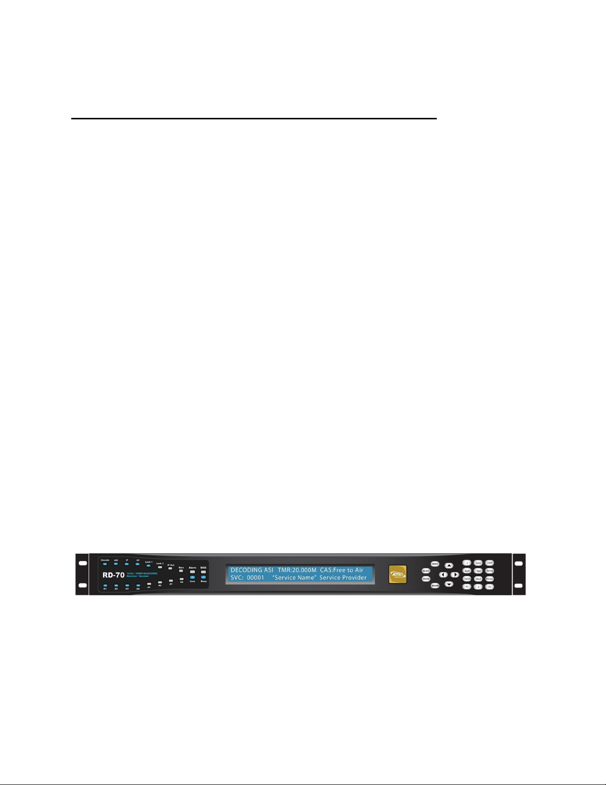
Front Panel
The front panel LCD and keypad can be used to configure and monitor your device.
Page 8

Front Panel LCD
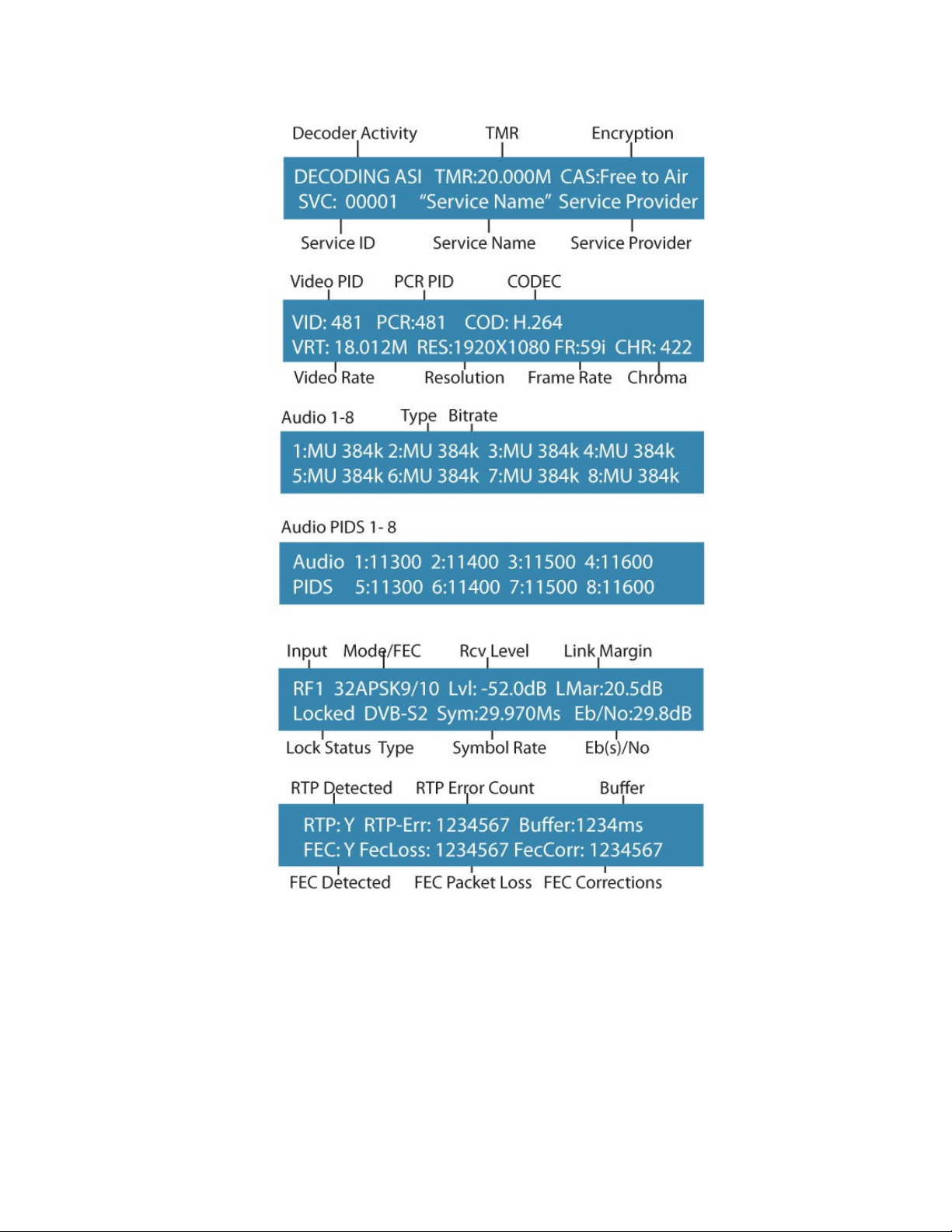
1) Feedback State: There are several quick view menu screens available when in regular
feedback state. You can view any of these quick view status screens by using the up and
down arrow buttons.
Page 9
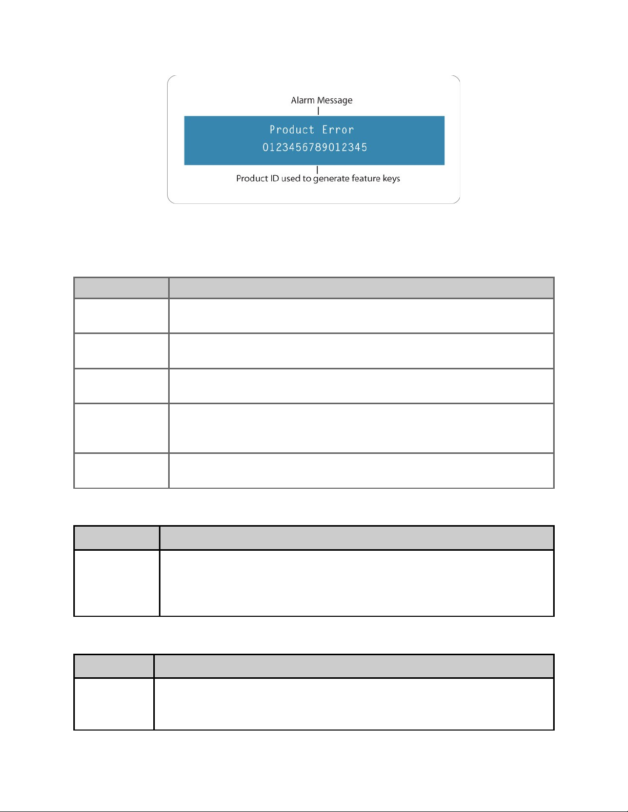
2) Disabled Product State: When the product is in a disabled state, the LCD will relay the
following information. This state is generally only used when a factory restore is performed.
If that is the case, note that all of the configurations have been returned to factory defaults
including Network configurations. To reapply network configurations simply press the Down
arrow when in this state to navigate through the network menu.
Page 10
Transport LED Indicators
Indicator Function
Decode Off - Decoder is idle.
On - Decoder is active.
ASI / IP /RF Off - No services detected on the input.
On - Services detected on the input.
Lock 1 / Lock 2 Off - Tuner is not locked
On - Tuner is locked
IP Out Off - IP Egress is idle.
On - IP Egress is active.
* IP Output is not available at this time
Bars Off - All B/T/ID options are disabled.
On - B/T/ID options are enabled.
Audio Decode Indicators
Indicator Function
A1 through A8 Off - Audio engine is not active.
On - Audio engine is actively decoding or performing passthru.
Blinking - Audio engine is in a failure mode ( no passthru or audio
decoding )
System Indicators
Indicator Function
Alarm Off - No system alarms.
On - System alarm.
(NTP or FAN alarm)
Page 11

BISS Off - Decryption configuration is turned OFF
On - Decryption configuration is set to BISS1 or BISSE
Link Off - Network communication link not detected
On - Network communication link detected
Busy Off - No network activity
On - Network traffic present
Controls
Using the Mode, Select, Enter, Escape, and directional buttons, the user can control the
unit via the front panel.
Control Function
Mode button Mode will cycle through top layer menus.
Select Select will enter into edit mode.
Enter Enter submits any edited configurations.
Escape Escape returns to the previous menu layer.
Cursor Arrows Arrows will navigate you within submenus
Programming
Keypad
For value entry. F1 functions as a “+” or “-” operator. F2 functions
as a “.” decimal or period.
Reset
Should you need to reset your device, you can do so via the front panel by pressing the MODE,
ESCAPE and RIGHT ARROW keys simultaneously.
Page 12
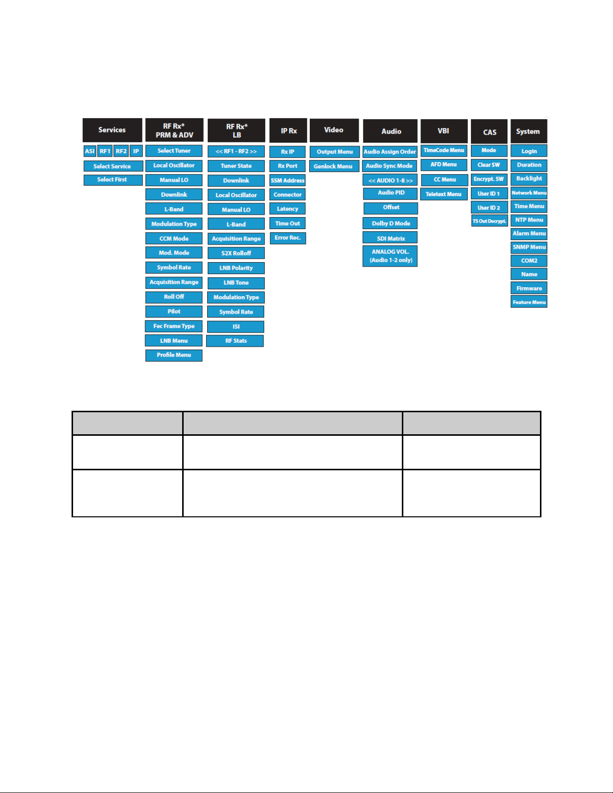
Front Panel Menu Structure
Services Menu
Item Function Options
List of Services Allows selection of a service from a list of
services per input.
Decode First Found Allows you to configure the RD-70 to
decode the first valid program found on
any input.
ALL ASI RF1 RF2 IP
ASI RF1 RF2 IP
Page 13

RF Rx Menu (ADV Advanced / PRM Premium)
Item Function Options
Select
Tuner*
Local
Oscillator
Manual LO Allows manual entry of the LNB Local Oscillator
Downlink Allows the operator to enter the satellite
Selects RF1 or RF2 as the RF acquisition source RF1
The Local Oscillator (L.O.) control specifies the
frequency of the LNB local oscillator. The
standard L.O. frequencies for “C” and “Ku” bands
are 5150MHz and 10750MHz respectfully
although, some other variants are included. If
the desired L.O. frequency is not listed, select
either C: Manual or Ku: Manual and enter the
L.O. frequency in the Manual L.O. field.
frequency provided that either C: Manual or Ku:
Manual is selected from the Local Oscillator
pulldown menu.
downlink frequency. The value for the Downlink
frequency is used with the Local Oscillator
frequency to calculate the L-Band frequency. The
Downlink and Local Oscillator frequencies can be
used to determine if spectrum inversion occurs
using the following rules. If the Downlink
frequency is less than the Local Oscillator
frequency, then spectrum inversion does occur.
If the Downlink frequency is greater than the
Local Oscillator frequency, then spectrum
inversion does not occur.
RF2
C: 5150
KU: 11300
KU: 10750
KU: 10600
KU: 10000
KU: 9750
KU: 9600
C: MANUAL
KU: MANUAL
Range dependent upon LO
configuration
L-Band Allows the operator to enter the L-Band
frequency within the range from 950MHz to
2.15GHz. The value entered in this field is used
with the Local Oscillator frequency to calculate
the Downlink frequency using the following rules.
If Downlink < Local Oscillator, then Downlink Local Oscillator = │L-Band│. If Downlink > Local
Oscillator, then Downlink - Local Oscillator = LBand
Modulation
Type
CCM Mode* When the Constant Coding and Modulation (CCM)
Allows the selection of the mod type. DVBS
option is selected, the same modulation mode
and FEC is used for all physical layer framing.
The advantage of using DVB-S2 in the CCM
mode is the improved protection that is achieved
by utilizing the new inner and outer codes.
Another advantage is the 30 percent increase in
950MHz - 2150MHz
DVBS-2
CCM
AUTO-CCM
Page 14

capacity that is realized while using the method.
If Auto-CCM is selected, the receiver will detect
and configure the Modulation Mode, Pilot, and
Frame Type.
Adaptive Coding and Modulation (ACM) is
available for receivers with the appropriate
hardware and feature key. In this mode,
modulation and coding can vary on a DVB-S2
frame by frame basis. Auto-CCM is the preferred
method to automatically detect modcod, pilots
and frame type. **This configuration is not
available via front panel at this time.
note: this field is not applicable for DVB-S.
Similar functionality (AUTO MODCOD detection)
can be used in DVB-S by using QPSK_AUTO or
8PSK_AUTO modulation modes.
Modulation
Mode
This control allows the operator to select the
desired modulation mode and FEC code rate.
note: This is a configuration value. When in
DVB-S2 AUTO-CCM mode, actual detected
modulation can be found in the Quick View
status. QPSK_AUTO and 8PSK_AUTO
configurations are only valid in DVB-S. See how
to appendix for automatic detection instructions.
We display all possible ranges
available via our device in the
Front Panel. This list will differ
from the list found in the web UI
as it only shows those options
available based on the hardware
and feature keys found.
QPSK-1/2
QPSK-2/3
QPSK-3/4
QPSK-5/6
QPSK-6/7
QPSK-7/8
QPSK-1/4
QPSK-1/3
QPSK-2/5
QPSK-3/5
QPSK-4/5
QPSK-8/9
QPSK-9/10
QPSK_AUTO*
8PSK-3/5
8PSK-2/3
8PSK-3/4
8PSK-5/6
8PSK-8/9
8PSK-9/10
8PSK_AUTO*
16QAM-3/4
16QAM-7/8
16APSK-2/3
16APSK-3/4
16APSK-4/5
16APSK-5/6
16APSK-8/9
16APSK-9/10
32APSK-3/4
32APSK-4/5
32APSK-5/6
32APSK-8/9
32APSK-9/10
Symbol Rate The number of symbols transmitted per second.
The amount of data per symbol is dependant
upon the modulation type, e.g. QPSK, 8PSK, etc.
Acquisition
Range
Acquisition Range is defined as the range of
frequencies that the tuner will scan in order to
achieve carrier synchronization. Allows the
operator to select the range of frequencies that
Range can be determined by
feature key.
0 - 7.5MHz
Page 15

the RF tuner will sweep through to acquire the
carrier. e.g. If the desired carrier is at 1.080GHz
and the Acquisition Range is set to 5MHz, the RF
tuner will sweep through 1.080GHz ± 2.5MHz to
acquire the carrier. Units are in MHz.
note: Actual acquisition range available is
symbol rate dependent for advanced and
premium demods. If symbol rate < 5MBaud,
maximum range is 1.5 * symbol rate. If
symbol rate > 5Mbaud, maximum range is
7.5MHz.
Rolloff The rolloff selection will determine the shape of
the input filter. The occupied bandwidth of the
modulated signal is the symbol rate multiplied by
(1+α) where alpha (α) is the rolloff factor (%).
By using a lower alpha, carriers can be spaced
closer together on a given transponder or an
increased symbol rate can be realized for a given
bandwidth.
note: 5%, 10%, and 15% rolloff is only
applicable in DVB-S2 with premium
demodulators. AUTO is only available in DVB-S.
Pilot DVB-S2 allows the option of inserting bursts of
pilot tones that are very robust and prevents the
carrier recovery system from failing prematurely.
However, when pilots are enabled, the total data
rate throughput is reduced by approximately
3.0%.
note: Pilot is not applicable in DVB-S or AUTOCCM modes.
FEC Frame
Type*
When operating in DVB-S2, the Frame Type
options are either Normal or Short. The Normal
64,800-bit FEC frame provides better protection
but introduces more latency compared to the
Short 16,200-bit FEC frame. Therefore, the Short
FEC frame type should be selected in
applications where latency is critical and the
longer frame type should be used to optimize
protection.
5%
10%
15%
20%
25%
35%
AUTO*
On
Off
N/A
Short
Normal
N/A
note: FEC Frame type is not applicable in DVB-S
or AUTO-CCM modes.
LNB Menu
LNB State This configuration will enable or disable power on
the input connector to power the LNB. If on, the
user selected voltage and tone will be placed on
the connector via the Polarity and Tone
ON
OFF
Page 16

configurations.
LNB Polarity This control is primarily used in “Universal” LNB
applications. The LNB Polarity control allows for
LNB polarization selection; the 13VDC source will
select the Vertical polarity and the 18VDC source
will select the horizontal polarity. For typical “C”
and “Ku” band applications, the 18 VDC option is
recommended.
LNB Tone This control is used only for Universal LNB
applications. A universal LNB can route the high
or low band from either polarity to the IRD. The
high band is selected by enabling the 22 kHz
tone and the low band is selected when the 0 Hz
tone is enabled.
Profile
Menu
Save Allows user to save currently running RF
configuration to a profile. Press <select> then
use keypad for custom name entry. Press
<enter> to confirm name and save profile.
Select Allows user to load profile from list. Press
<select> then <up> and <down> arrows to list
profiles. press <enter> to load selected profile.
H(18V)
V(13V)
0KHz
22KHz
Delete Allows user to delete profile from list. Press
<select> then <up> and <down> arrows to list
profiles. press <enter> to delete selected
profile.
RF Rx Menu (LB L-Band)
Item Function Options
Tuner State Enables or Disables RF input.
note: When RF1 and RF2 are both enabled,
maximum tuner performance is affected. Please
view table in Appendix A for symbol rate and
modcod resource limitations.
Downlink Allows the operator to enter the satellite
downlink frequency. The value for the Downlink
frequency is used with the Local Oscillator
frequency to calculate the L-Band frequency. The
Downlink and Local Oscillator frequencies can be
used to determine if spectrum inversion occurs
using the following rules. If the Downlink
frequency is less than the Local Oscillator
frequency, then spectrum inversion does occur.
DISABLED
ENABLED
Range dependent upon LO
configuration
Page 17

If the Downlink frequency is greater than the
Local Oscillator frequency, then spectrum
inversion does not occur.
Local
Oscillator
Manual LO Allows manual entry of the LNB Local Oscillator
L-Band Allows the operator to enter the L-Band
Acquisition
Range
The Local Oscillator (L.O.) control specifies the
frequency of the LNB local oscillator. The
standard L.O. frequencies for “C” and “Ku” bands
are 5150MHz and 10750MHz respectfully
although, some other variants are included. If
the desired L.O. frequency is not listed, select
either C: Manual or Ku: Manual and enter the
L.O. frequency in the Manual L.O. field.
frequency provided that either C: Manual or Ku:
Manual is selected from the Local Oscillator
pulldown menu.
frequency within the range from 950MHz to
2.15GHz. The value entered in this field is used
with the Local Oscillator frequency to calculate
the Downlink frequency using the following rules.
If Downlink < Local Oscillator, then Downlink Local Oscillator = │L-Band│. If Downlink > Local
Oscillator, then Downlink - Local Oscillator = LBand
Acquisition Range is defined as the range of
frequencies that the tuner will scan in order to
achieve carrier synchronization. Allows the
operator to select the range of frequencies that
the RF tuner will sweep through to acquire the
carrier. e.g. If the desired carrier is at 1.080GHz
and the Acquisition Range is set to 5MHz, the RF
tuner will sweep through 1.080GHz ± 2.5MHz to
acquire the carrier.
C: 5150
KU: 11300
KU: 10750
KU: 10600
KU: 10000
KU: 9750
KU: 9600
C: MANUAL
KU: MANUAL
950MHz - 2150MHz
0 - 5MHz
S2X Rolloff S2X Rolloff will allow the tuner to operate in an
optimized mode for roll-offs of 15% or less.
When disabled, it will operate in standard 20% 35% as defined by the incoming S2 BBHeader.
Due to modulation manufacturers providing
backwards compatibility during S2 to S2X
migration, this must be manually configured for
the best 5%, 10% and 15% roll-off performance.
LNB Polarity This control is primarily used in “Universal” LNB
applications. The LNB Polarity control allows for
LNB polarization selection; the 13VDC source will
select the Vertical polarity and the 18VDC source
will select the horizontal polarity. For typical “C”
and “Ku” band applications, the 18 VDC option is
recommended.
DISABLED
ENABLED
OFF
H(18V)
V(13V)
Page 18

LNB Tone This control is used only for Universal LNB
applications. A universal LNB can route the high
or low band from either polarity to the IRD. The
high band is selected by enabling the 22 kHz
tone and the low band is selected when the 0 Hz
tone is enabled.
0KHz
22KHz
Modulation
Type
Symbol Rate The number of symbols transmitted per second.
ISI ISI (input stream identifier) is required for
Allows the selection of the mod type. AUTO
The amount of data per symbol is dependant
upon the modulation type, e.g. QPSK, 8PSK, etc.
Set this field to 0 for automatic Symbol Rate.
multistream applications. If a multistream RF
source is detected, BBHeaders containing this
value will be demodulated and output to the
receiver. This value has no effect during single
stream applications.
RF Stats
Menu
RF Stats General RF Lock Status is provided via the RF
quickview menu, but a detailed list of further
information can be found in this menu.
DVBS
DVBS-2
0 = AUTO
Range can be determined by
feature key.
0 - 255
Page 19

IP Rx Menu
Item Function Options
Multicast RX IP Multicast IPA sets the multicast receive
Group IP address. IP Multicast receiving is
supported from compatible streamers. The
range of the multicast group IP is
224.XXX.XXX.XXX to 239.XXX.XXX.XXX XXX represents any number 0 through 255.
This can be either regular class A, B, C IP
address or a multicast IP address.
Multicast RX
Port
Source Specific
Multicast
Address
Port number are used for receiving UDP/RTP
transfers in conjunction with Multicast IPA.
The valid range is 0-65535. If the port
number is set to 0, then no UDP transfers
will take place. 2000 is default.
Configures the multicast receive Source
Specific IP Address. This configuration
should be configured to 0.0.0.0 (any source
multicast) in most IGMPv2 multicast
applications. This configuration is an
advanced configuration used for
redundancy, security, or IGMPv3 multicast
applications. It does not function for unicast
reception.
0.0.0.0 -
255.255.255.255
0 - 65535
0.0.0.0 -
255.255.255.255
Multicast
Connector
Latency Multicast Latency sets the latency delay
Multicast
Timeout
The multicast connector configuration
determines the physical port of where the IP
stream will be received, the ethernet
(10/100) or gigabit (10/100/1000) ethernet
port.
before the decoder begins playback from the
multicast source and should be argued as a
millisecond value.
If the MULTICASTLATENCY delay time is too
large, and the internal delay buffer is about
to overflow, the system will start the
multicast playback early to prevent the
overflow. A log message is generated when
this condition occurs.
Sets the timeout value for return to normal
video playback after video multicast packets
are no longer detected. The default timeout
ETHERNET
GIGE
4ms min. - max (rate
dependent)
500ms (default)
33 - 30000ms
300ms (default)
Page 20

value is 300 milliseconds. If the timeout
value is set too low, the multicast receive
may timeout during normal reception if the
packet transmission is bursty.
Multicast Error
Recovery
Multicast Error Recovery sets the timeout
value for recovery of multicast receive after
decoder error condition is detected.
The default error recovery timeout is
configuration value is 10000 milliseconds.
Video Menu
Item Function Options
Output Menu
Fault Mode Display or Modify the current SDI
video fault setting. This setting
sets the video resolution when in
video fault.
This setting will be applied on
startup when no video is present.
If video becomes present, the
setting will be overridden by the
current video setting.
Video Loss When video is not detected on
the configured input, this setting
will define the output.
480i59.94
576i50
720p59.94
720p50
1080i59.94
1080i50
1080p59.94
1080p50
OFF:No video output on fault
BLANK:Only blanking on fault
33 - 600000ms
10000ms (default)
BLANKTONES: Blanking and tones
on fault
BLANKOVERLAY: Blanking and
overlay on fault
BLANKTONESOVERLAY
Blanking, tones and overlay
on fault
When a type with BLANK is selected,
the current bars/matte setting will
be applied.
When a type with TONES is
selected, the current tones setting
will be applied.
When a type with OVERLAY is
Page 21

selected, the current device name
will be used.
3G Mapping
Level SDI
3G Mapping
Level SDIALT
SDI 3G Level controls the
mapping of the 3G-SDI signal
when decoding 1080P50,
1080P59.94 and 1080P60
streams. The 3G-SDI signal can
be mapped to Level A or Level B
Dual Link. The mapping is
individually configurable for each
set of outputs (SDI and SDIALT).
If 3G-SDI output does not
appear on the downstream
device, the device may not
support the currently configured
mapping mode. Use SDI3GLEVEL
to change the mapping mode.
A
B
A
B
Downscaling
SDI
Downscaling
SDIALT
Genlock Menu
Genlock Mode Configures the genlock operation
The Downscaling SDI setting
determines whether the SDI
bank ( SDI Output 1 and 2 ) will
be output natively or downscaled
to SD.
The Downscaling SDI setting
determines whether the SDI
bank ( SDI Output 3 and 4 ) will
be output natively or downscaled
to SD.
of the decoder. SLAVE is
primarily used for 3D applications
OFF
SD
OFF
SD
OFF - Disables genlock
SLAVE - Enable Genlock, Decode
source is synchronous to SYNC IN
Page 22

and REMOTE is used in standard
genlock operation.
signal
REMOTE - Enable genlock, Decode
source is NOT synchronous to SYNC
IN signal
Horizontal
Adjust
Vertical Adjust Vertical adjustment defines the
Pixel Phase Pixel Phase adjustment is a very
Genlock Status Shows if GENLOCK input is
Horizontal adjustment defines
the difference in the SYNC IN
HSYNC and output HSYNC.
Typically, this should be in the
range of 0 to +1 line in clocks.
For example, a 1080I output
could be adjusted from 0 to
2200.
difference in the SYNC IN VSYNC
and output VSYNC. Typically, this
should be in the range of 0 to +1
frame in lines. For example, a
1080I output could be adjusted
from 0 to 1125.
fine grain adjustment that can
adjust within a single clock. The
increments are 1/64th of a clock.
The valid range is 0 to 63.
currently being used for the
decoder or in FREE RUN mode
0 - 2200
0 - 1125
0 - 63
Genlock CVBS
Out
Genlock Reset Reinitializes the Genlock System.
This configuration is used
generally with 3D applications.
The ‘MASTER’ unit CVBS
configuration must be configured
as ‘SYNC’.
VIDEO - CVBS output is video
SYNC - CVBS output is black burst
sync signal
Page 23

Audio Menu
Item Function Options
Audio Assign
Order
Audio Sync
Mode
The RD automatically assigns
audio PID's to audio engines
upon stream acquisition. This
setting determines if the audio
assignment should be done in
PID Ascending order, the Adtec
default, or PMT order. Some
legacy IRD's use PMT order.
Audio Sync Mode determines
how the audio sub-system
should behave with incoming
transport streams. When it is
desired for the audio
subsystem to retain tight
lipsync and adjust on
upstream lip sync changes,
this should be configured for
Professional, the default
setting. In rare cases, third
party encoders or multiplexers
may have unstable PCR/PTS
timing. In these cases
professional may cause
intermittent drop outs as the
audio sub-system attempts to
retain tight lip sync. If this
occurs, please change lipsync
setting to Relaxed.
PID ORDER (default)
PMT ORDER
PROFESSIONAL (default)
RELAXED_20_MS
RELAXED_80_MS
RELAXED_1_S
Audio 1-8
Audio PID Allows selection of available
audio PID associated with
program. note: Selection list
only shows PIDs listed in PMT.
Manual PID entry (such as IFB
applications) is only available
via the UI and SNMP at this
time.
Offset Pair Adjusts each individual pairs of
audio sync.
DISABLED
AUTO (default)
* shows PID list from actively decoding
program
-50 - 800ms
Page 24

DolbyD
Mode
Configures the audio engine to
Pass-through ( COMPRESSED )
or decode ( 2/0 STEREO ) if a
Dolby Digital AC3 PID is
detected for the selected Audio
input. Mpeg1Layer2 always
decodes, and LPCM / Dolby E
always Pass-through,
regardless of this setting.
Dolby Decode requires feature
key capability.
PASSTHRU (default)
DECODE - STEREO*
DolbyE Line This is used to configure Dolby
E placement in the SDI output
and is configurable per audio
engine. When set to AUTO (-
1), the default configuration,
the Dolby E line is placed
within the valid line number
range for the video resolution.
The Dolby E line may be
manually configured to a value
within range. Valid ranges for
Dolby E line placement are
resolution and frame rate
dependent. If the configured
value is not valid, the system
will use the valid line used by
the 'AUTO' mode. The Dolby E
line status information can be
used to see the actual Dolby E
line placement.
View Dolby E line table for
more information.
-1 - 4096
-1 = AUTO
Analog Vol.
Pair 1 & 2
SDI Audio
Matrix 1-8
SDI Audio
Matrix
Adjusts the analog volume of
the first pair in dB increments
The SDI audio matrix allows
the user to route, duplicate, or
disable audio pairs within the
SDI embedded output.
-49 - 18 dBu
DISABLE, Disable audio output on
selected SDI pair
AUTO, default, Invokes automatic SDI
pair assignment. This is the default
setting.
AUDIO1, Route Audio 1 to the selected
SDI pair
AUDIO2, Route Audio 2 to the selected
Page 25

SDI pair
AUDIO3, Route Audio 3 to the selected
SDI pair
AUDIO4, Route Audio 4 to the selected
SDI pair
AUDIO5, Route Audio 5 to the selected
SDI pair
AUDIO6, Route Audio 6 to the selected
SDI pair
AUDIO7, Route Audio 7 to the selected
SDI pair
AUDIO8, Route Audio 8 to the selected
SDI pair
Page 26

VBI Menu
Item Function Options
Time Code
SDI Line Number Configures the SDI ANC line output of VITC/LTC
( SDI Output Port 1 and 2 )
SDI Alt. Line
Number
Source If timecode is carried by a PES stream,
SDI Output Configures the SDI ANC timecode output for
SDI Alt. Output Configures the SDI alternate ANC timecode
AFD
Configures the SDI Alternate ANC line output of
VITC/LTC ( SDI Output Port 3 and 4 )
configure the RD-70 Timecode Source to PES
(default). If a PES time code PID is not
available, the RD-70 can extract the time code
from the GOP by configuring Timecode Source
to VIDEO.
PASS ( preserve timecode type from transport
stream ), only output LTC, only output VITC, or
output both.
output for PASS ( preserve timecode type from
transport stream ), only output LTC, only output
VITC, or output both.
0 - Disabled
7 - 22
0 - Disabled
7 - 22
PES
VIDEO
PASS
LTC
VITC
BOTH
PASS
LTC
VITC
BOTH
SDI Line Number Configures the SDI ANC line output of AFD (
SDI Output Port 1 and 2 )
SDI Alt. Line
Number
Closed Captions
CVBS Line
Number
SDI Line Number Configures the SDI ANC line output of EIA-
SDI Alt. Line
Number
Configures the SDI Alternate ANC line output of
AFD ( SDI Output Port 3 and 4 )
Enables/Disables the CVBS/SD-SDI port line
number for waveform closed captions.
608/708 Closed Captions ( SDI Output Port 1
and 2 )
Configures the SDI Alternate ANC line output of
EIA-608/708 Closed Captions ( SDI Output Port
3 and 4 )
0 - Disabled
7 - 22
0 - Disabled
7 - 22
0 - Disabled
21 - Output captions
if present
0 - Disabled
7 - 22
0 - Disabled
7 - 22
Page 27

Teletext
CVBS Line
Number
SDI Line Number Configures the SDI ANC line output of
SDI Alt. Line
Number
Enables/Disables the CVBS/SD-SDI port line
number for waveform Teletext.
OP47/Teletext ( SDI Output Port 1 and 2 )
Configures the SDI Alternate ANC line output of
OP47/Teletext ( SDI Output Port 1 and 2 )
0 - Disabled
22 - Output teletext
if present
0 - Disabled
7 - 22
0 - Disabled
7 - 22
Page 28

CAS Menu
Item Function Options
Mode Configures the current decryption setting. OFF
BISS_1
BISS_E_USER_ID_ON
E
BISS_E_USER_ID_TW
O
Clear Session Word The session keys used for decryption.
[MODE BISS_1] uses a 12-digit
hexadecimal Clear Session Word.
Encrypted Session
Word
User ID One Valid in Mode BISS_E_USER_ID_ONE
User ID Two Valid in Mode BISS_E_USER_ID_ONE
TS Out Decrypt The TS Out Decrypt configuration
The 16-digit hexadecimal Encrypted
Session Word for use with BISS_E modes.
ONLY. The 14-digit hexadecimal User ID
(injected ID) used for decryption.
ONLY. The 14-digit hexadecimal User ID
(injected ID) used for decryption.
determines if the ASI output should mirror
the selected input (OFF), thus preserving
any encrypted streams or if it should be
decrypted / free to air (ON).
OFF, the default configuration, is
recommended for users needing to
redistribute transport streams in their
original form. The decoder will decrypt /
decode the selected program with the
entered BISS key, but the ASI output will
remain unaltered.
ON is recommended for users needing to
redistribute the ASI output as a free to air
SPTS/MPTS. All programs will be
decrypted with the user entered BISS key.
user-defined using the
numeric keypad
user-defined using the
numeric keypad
user-defined using the
numeric keypad
user-defined using the
numeric keypad
OFF
ON
Page 29

System Menu
Login
Units ship with the front panel logged in by default. If you become logged out and are
prompted for a password, use the following key sequence for access.
note: The key sequence can be remembered by using the word ‘USER’ for ‘Up, Select,
Enter, Right’.
Action
Press <Select>
Press <Up> arrow
Press <Select>
Press <Enter>
Press <Right> arrow
Press <Enter>
Duration
The front panel also has a login duration feature. This setting allows the user to specify a
time frame (in minutes) until the unit will automatically log itself out.
Action
Press mode until you see the System Menu.
Press <Select>
Press the <Down> arrow
Press <Select>
Using the <Up> and <Down> arrows, select the value you wish.
Press <Enter> to save your selection
Possible Configurations:
0 (Zero): The unit will not automatically log out.
1-9: The duration of time, in minutes, before the unit logs out, if no input is received.
Page 30

Page 31

Item Function Options
Network Menu
Ethernet IP Address This is the address of your device
on your network specific to the
Ethernet Port.
Ethernet Mask Defines the unit relative to the
rest of your network.
Ethernet DHCP The Dynamic Host Configuration
Protocol allows your device to
self-locate network Ethernet
parameters.
GigE IP Address This is the address of your device
on your network specific to the
GigE Port.
GigE Mask Defines the unit relative to the
rest of your network.
user-defined using the numeric
keypad
Default is 192.168.10.48
user-defined using the numeric
keypad
Default is 255.255.255.0
On (finds own DHCP Address)
Off (defaults to last entered IP
Address)
Default is OFF
user-defined using the numeric
keypad
Default is 192.168.20.48
user-defined using the numeric
keypad
GigE DHCP The Dynamic Host Configuration
Protocol allows your device to
self-locate network GigE
parameters.
Gateway IP Address The gateway is a routing
mechanism that passes traffic
between different subnets and
networks.
Stealth IP Address This is a security feature that
allows only the designated
Stealth IP Address to
communicate with the unit for
FTP and other services. This
control allows one-point override
Default is 255.255.255.0
On (finds own DHCP Address)
Off (defaults to last entered IP
Address)
Default is OFF
user-defined using the numeric
keypad
Default is 192.168.10.1
user-defined using the numeric
keypad
Default is 0.0.0.0. Using all 0s
effectively turns this function
off.
Page 32

access to the Stealth IP Address.
Time Menu
Time Defines system time user-defined using the numeric
keypad
Timezone Defines the time zone the unit
operates in
NTP Menu
NTP Status Network Time Protocol SYNC
status
NTP IP Address IP address designated for
Network Time Protocol
Alarm Menu
Event Record Log of events outside of regular
operating parameters
SNMP Menu
SNMP Controls the status (ON/OFF) of
the Simple Network Management
Protocol (SNMP) feature. We
support SNMPv2c.
Read-only
community
The Simple Network Management
Protocol (SNMP) Read-Only
Password. Default Value: "adtec"
Read-only
user-defined using the numeric
keypad
Default is 0.0.0.0. Using all 0’s
effectively turns this function
off.
scroll up and down to view log
items
OFF
ON
user-defined using the numeric
keypad
default: adtec
Read-write
community
Trap Community The Simple Network Management
Trap Sink The Simple Network Management
The Simple Network Management
Protocol (SNMP) Read-Write
Password. Default Value: "none"
Protocol (SNMP) trap community.
Default Value: "public"
Protocol (SNMP) trap sink,
destination for sending SNMP
traps. Default Value:
"127.0.0.1" / localhost.
user-defined using the numeric
keypad
default: none
user-defined using the numeric
keypad
user-defined using the numeric
keypad
Page 33

Com2
Item Function Options
Com2 Settings RS-232 terminal monitor for
communicating with the
internal host motherboard for
diagnostics.
115200 8 1 NONE
57600 8 1 NONE
38400 8 1 NONE
19200 8 1 NONE
9600 8 1 NONE
Default is 38400 8 1 None
Host Name
Item Function Options
Host Name The hostname of the unit. This
name is be used by unit to
broadcast zero-conf name and
is viewable in web-browser
title bar
Read-Only
Firmware
Item Function Options
Firmware
Version
Reports the currently running
firmware version of your
device.
Read-Only
Feature Menu
Item Function Options
Permanent ID Shows the units unique
permanent identifier. This ID
is required by support when
purchasing unit capability
keys.
Temporary ID Shows the units unique
temporary identifier. This ID
is required by support to
provide temporary unit
capability keys.
If all 0’s, your unit is not
temporary key capable.
Read-Only
Read-Only
Page 34
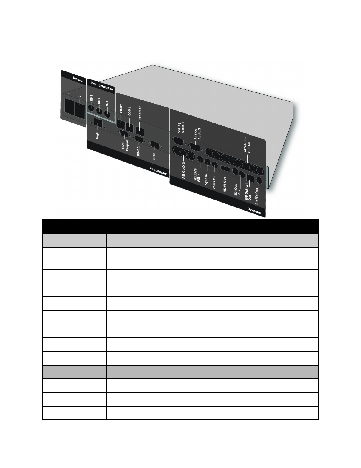
Back Panel
Connector Description
Processor
Power 1 & 2 Redundant AC Power, Standard 3 pin computer power plug
(Auto range 70-240 VAC Input)
GigE UDP or RTP multicast transport ingress port (SMPTE 2022)
COM2 API Serial Communication Interface **
COM1 Serial Port Used for Troubleshooting (Terminal)
Ethernet 10/100 base T ethernet interface (Monitoring/Management)
DVC Parport 9-pin parallel I/O interface for control systems **
RS422 Not Currently Supported **
GPIO Tally and Control Port
Decoder
Analog Audio Out Balanced analog audio out. Stereo pairs 1 & 2 ( 600 Ohm Balanced )
AES Audio Out 1-8 x8 75 Ohm AES-3 BNC
ASI/SDI In 75 Ohm terminated BNC input. SDI input features are not active at
Page 35
this time.
x3 ASI OUT x3 75 Ohm BNC ASI output per EN5000839
Sync In Standard analog video sync separation for NTSC, PAL, 480I/P,
576I/P, 720P, and 1080I/P/PsF from Composite Video (CVBS). Bilevel & tri-level sync compatible. BNC
CVBS Out 75 Ohm BNC Standard Definition Composite Video Output
Digital Video Video Output
SDI Out Banks x4 Outputs from decoder: Video/Audio/VBI (SMPTE 259M-C - SD,
SMPTE 292M - HD, SMPTE 424M - 3G).
SDI Bank A = x2 SD/HD/3G-SDI BNC Outputs
SDIALT Bank B = x1 SFP(for Optical SFP connector) SD/HD/3G-SDI
Output and x1 SD/HD/3G-SDI BNC.
note*: 3G-SDI Outputs have selectable Level A and Level B Dual
Link output control to retain interoperability with other third party
3G devices. The default mapping level is Level A.
Demodulator
(Optional)
RF 1 & 2 x2 RF Input, 75 Ohm F-Connector
DB9-M Analog audio output pinout
PIN Designation Function
1 NC No Connect
2 GND
3 L+ Left +
4 R+ Right +
5 GND Ground
6 NC No Connect
7 GND Ground
8 L- Left -
9 R- Right -
Ground
Page 36

COM1/COM2 to DB9 Serial Adapter
The COM1 and COM2 port is an industry standard RS-232 DTE device on RJ45/RJ48. Units
ship with RJ45 to DB9 adapters that are pinned per the following.
DB9 PIN DB9 Function RJ45 Pin RJ45 Function
1 Carrier Detect (CD) 2 No Connect / Carrier Detect (DCD)
2 Receive Data (RXD) 6 Transmit Data (TXD)
3 Transmit Data (TXD) 5 Receive Data (RXD)
4 Data Terminal Ready
(DTR)
5 Ground (GND) 4 Ground (GND)
6 Data Set Ready (DSR) 3 Data Terminal Ready (DTR)
7 Request to Send (RTS) 7 Clear to Send (CTS)
8 Clear to Send (CTS) 8 Request to Send (RTS)
9 Ring Indicator (RI) NC / NA No Connect / Not available on RJ45
1 Data Set Ready (DSR)
GPIO and Parport information
The GPIO port allows decoder control and TTL voltage output for monitoring systems.
The GPIO feature is not enabled at this time.
The DVC Parport allows custom events to be programmed upon input pin voltage
change. It contains 4 available inputs for custom commands. Please contact technical
support for advanced usage in programming the parallel port.
GPIO Pinout
PIN Designation Function
1 NC No Connect
2 D3 reserved for future functionality
Page 37

3 D2 reserved for future functionality
4 D1 reserved for future functionality
5 D0 reserved for future functionality
6 NC No Connect
7 5VDC +5V DC
8 GND ground
9 TTL Tally reserved for future functionality
Parport Pinout
PIN Designation Function
1 NC No Connect
2 D3 Data bit 3 (input)
3 D2 Data bit 2 (input)
4 D1 Data bit 1 (input)
5 D0 Data bit 0 (input)
6 NC No Connect
7 5VDC +5V DC
8 GND ground
9 NC No Connect
Page 38

Chapter 2 - Getting Connected
Introduction to the Control Application
A web-based control software application comes pre-installed on the RD-70.
Compatible browsers
Firefox (recommended)
MS Internet Explorer
Safari
Chrome
Ethernet Access
To begin, you will need to connect to your RD-70 via Ethernet directly, or by adding the RD70 to your local area network. The default address for all Adtec devices is 192.168.10.48.
To connect directly to the device, make sure that your computer and the device have IP
addresses within the same IP class range.
(ex. 192.168.10.48 for the device and 192.168.10.49 for your computer).
If you need to change the IP address of the device, this can be done via the front panel,
System > Network menu. Using a CAT 5 crossover cable, connect one end to your computer
and the other to the Ethernet port found on the processor section of the back panel. (Some
computers can auto negotiate the connection and a crossover may not be necessary.)
To add the device to a LAN, connect a standard CAT 5 Ethernet cable to your network router
and then to the Ethernet port on the back of the device. If your network is DHCP enabled
and you prefer that over a static IP, you can turn on DHCP for the device via the front panel,
System > Network menu.
Zero Configuration Access
Adtec Digital has adopted zero-configuration networking technology, streamlining the setup
and configuration processes for our products. The use of this technology enables automatic
discovery of Adtec devices and services on an IP network. Used in tandem with the webbased control and configuration applications we can now provide 1-click access to any
device.
By using the built-in Bonjour locater in Apple's Safari browser or the plug-ins readily
available for IE or Firefox browsers, users can locate all of the Adtec devices on a network
by referencing the serial number on the back of the device. Clicking on the unit in the
Bonjour list will re-route you to a login page. If you do not wish to use Bonjour, you can
Page 39

reach the device’s web application by pointing your browser to the IP Address of the device.
Ex.http://192.168.10.48/.
Login
Once you reach the default login page for the web-based application, you will need to login
by pressing the login button. You will be prompted for a username and password. The
default username is ‘adtec’. The default password is ‘none’.
The left-hand panel of the application will report current status in real-time while the right
panel tabs will allow you to configure your device. As you navigate through the web
application look for the ? icons associated with each parameter. By clicking on these
question marks, you can view additional information about how the parameter is used.
Firmware Upgrade via Web User Interface
Periodically, we will provide firmware updates to our products via our website.
(http://www.adtecdigital.com) To upgrade your device, download the firmware file from our
website and store it locally. Login to the web-based application and navigate to the Upgrade
> Firmware tab. Click on the upload button located at the top right of the application. Select
the firmware file from your local machine and wait for it to upload. Once it has finished
uploading, it will appear in the Available Versions list.
Page 40
Click on the Install button associated with the new file. Wait for it to completely extract and
become available in the Installed Versions List. Once available there, simply click on the
Select button associate with the new firmware and wait for your device to reboot.
Demodulator Firmware Upgrade via Web User Interface
In some cases, Adtec may provide a modulator or demodulator firmware upgrade. These
are handled separately than standard product firmware upgrades because they can take
longer than a product firmware update and should be planned during maintenance windows.
Adtec currently has several demodulator versions that include ADV, LB and PRM models.
Each demodulator hardware type has a unique demod firmware version and must be
upgraded with a compatible version.
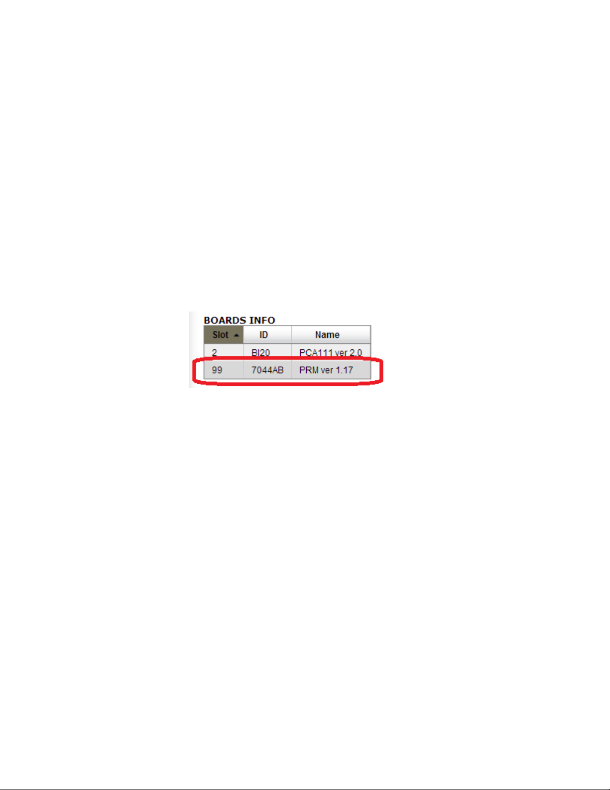
To upgrade, first determine the installed demodulator type and firmware version. Visit the
Upgrade -> Features tab. The ‘BOARDS INFO’ table slot 99 will contain the installed
demodulator version.
The above example shows a PRM demod running demod version 1.17. In this case, a
7044AB firmware file name is required to update this demodulator. If a demodulator
firmware is provided for any reason, please make sure the firmware type provided matches
the hardware type of the unit it is being installed on. The demod firmware may be
upgraded similarly to a product firmware upgrade.
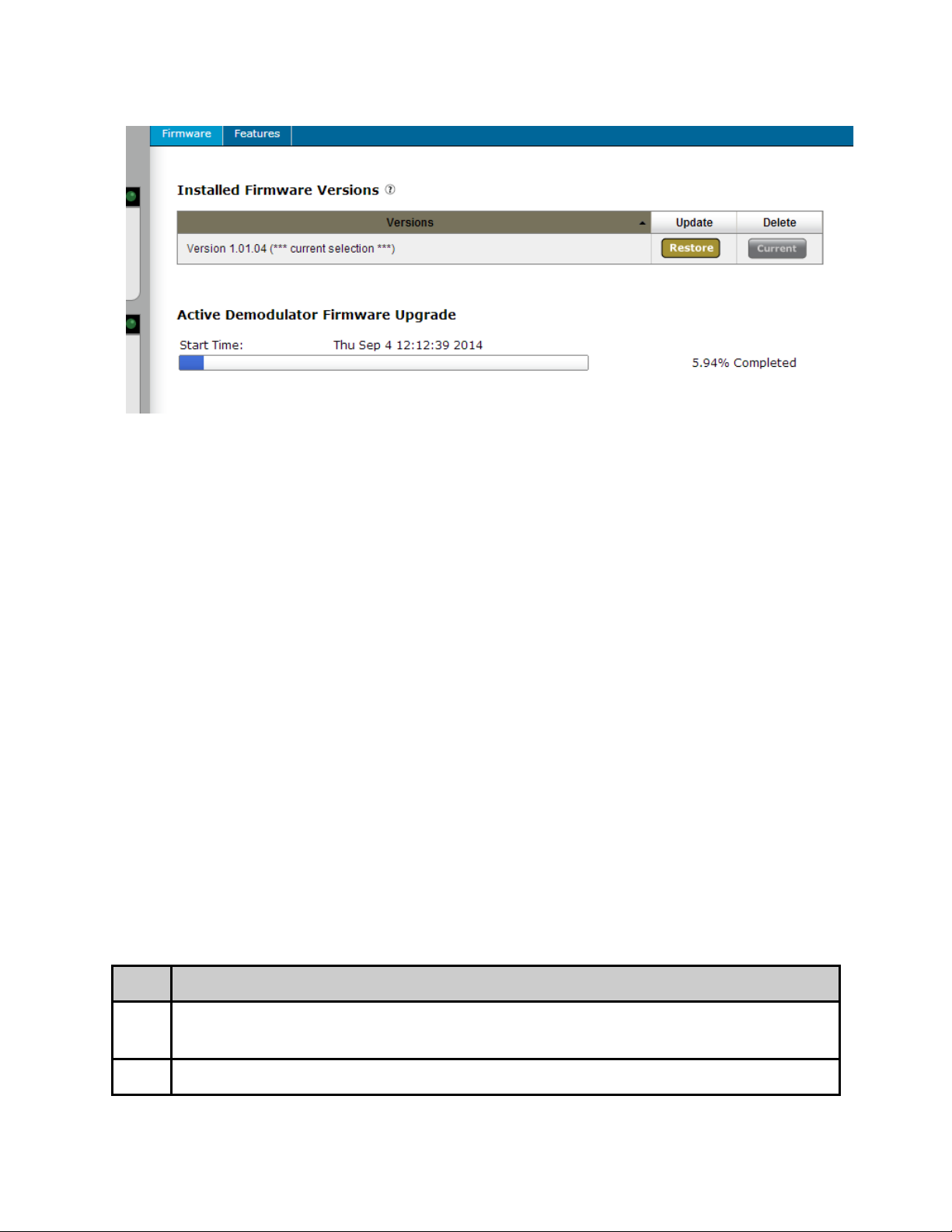
Click on the upload button located at the top right of the application. Select the firmware
file from the local computer and wait for it to upload. Once it has finished uploading, it will
appear in the Available Demodulator Versions list.
Page 41

The time required to update firmware varies on hardware model and should be accounted
for during the maintenance windows.
Estimated Time required to update firmware:
LB Demod firmware update - ~6 minutes
ADV Demod firmware update - ~12 minutes
PRM Demod firmware update - ~26 minutes
Once the version is seen on the Upgrade -> Firmware tab, click ‘SELECT’ to start the
upgrade process. A status bar will appear and will progress as the firmware update
commences. When the firmware update is complete, reboot the unit and verify the
firmware version again on the Upgrade -> Features Tab.
Page 42
!!NOTE!! It is only recommended to update during a planned maintenance window. If a
firmware upgrade fails for any reason, it is OK. Just try the upgrade again by clicking on
the ‘SELECT’ button. The upgraded version can be verified by visiting the Upgrade ->
Features tab after reboot. It is recommended to delete the file after a successful upgrade
by clicking the ‘DELETE’ button.
Upgrading via FTP & Telnet
For those times when using the web user interface is not convenient, you can upload the
firmware file via ftp and then extract and select into it via Telnet.
File Transfer Protocol (FTP)
FTP connections can be made to the Adtec device using any ftp client.
Host: <ipa of the unit>
Default Username: adtec
Default Password: none
Port: 21
You will want to drop the firmware file in the media/hd0/media folder.
Telnet (standard 23 port)
To connect to your unit using a terminal session you will need to set the IP address of the
unit. See earlier instructions on setting the IP via the front panel.
Using a terminal window, complete the following:
Step Action
1 Type 'telnet x.x.x.x' in a terminal window, without quotes, where x.x.x.x is the IP
address of the unit.
2 Press <Enter>.
Page 43

3 When prompted for a username, enter adtec.
4 When prompted for a password, enter none.
Once you see "User 'adtec' connected", the session is open and you may issue API
commands to the unit.
To extract and select into the new firmware version you have uploaded, issue the following
commands.
*.sysd version search
Copy the line designating the location of the new file.
Then type:
*.sysd version extract “copied path to new file”
Wait for the extraction to complete. Once complete, type the following command:
*.sysd version
Copy the line referencing the firmware version you wish to use and then issue the following
command.
*.sysd version select “copied new firmware version”
Once you press enter, this will reboot your device into the new version.
Page 44
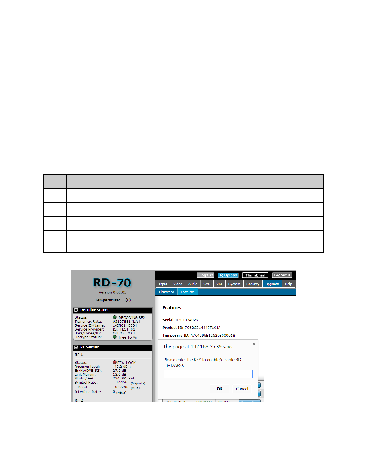
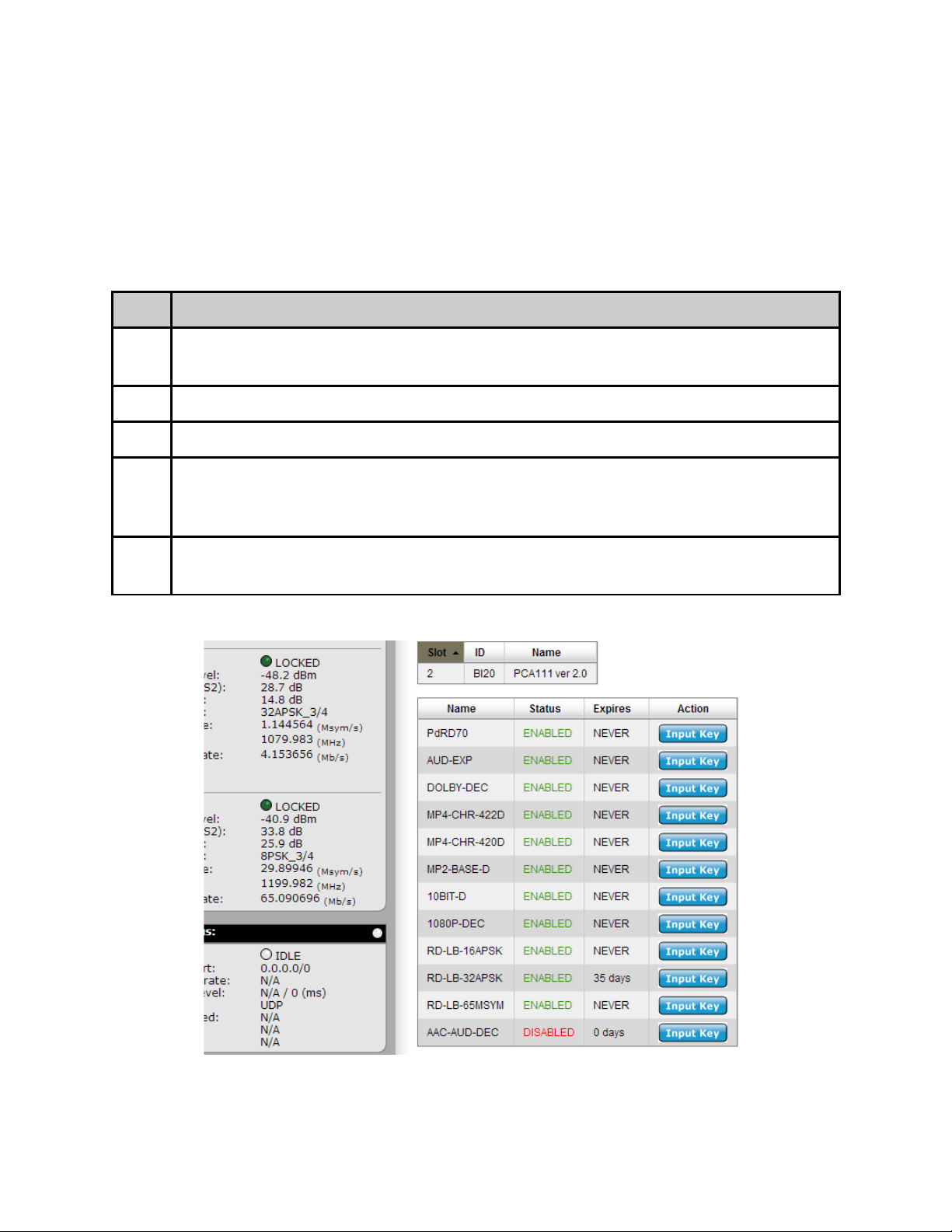
In Field Feature Upgrades
Unit features can be upgraded in the field via the web user interface. Keys can either be
temporary (feature will stop working after a set amount of time) or permanent (key is good
for the life of the product). To purchase a permanent key, please provide your unit serial
number and product ID from the Upgrade -> Features tab to your sales representative. If a
temporary key is required, the Temporary ID will also be required.
Permanent Key Instructions
A permanent unlock key can be provided via email or verbally if internet access is not
available. To enter the unlock key:
Step Action
1 Click on the ‘Input Key’ button next to the desired feature.
2 Enter the supplied key into the pop-up dialog box and click OK.
3 The feature status should change from ‘DISABLED’ to ‘ENABLED’.
4 In some cases, a reboot of the unit may be required after a state change to
‘ENABLED’. Reboot unit if enabled feature does not function.
Page 45
Temporary Key Instructions
If a temporary key is provided, it will be in the form of an email attachment or file.
Temporary keys are not entered through the ‘Input Key’ button. Instead, they are
transferred to the unit through the use of the file transfer utility via the ‘Upload’ button.
The ‘Upload’ button is found in the top right hand corner of the Web UI.
Step Action
1 Download the temporary key file to your computer provided by your
representative.
2 Click on the ‘Upload’ button in the top right hand corner of the Web UI.
3 Browse for the supplied ‘ASC’ file from the file browser pop-up and click ‘Open’
4 The page should reload and feature status should change from ‘DISABLED’ to
‘ENABLED’ with a ‘Days Left’ count. This count determines how many days the
key will function before returning to a ‘DISABLED’ state.
5 In some cases, a reboot of the unit may be required. Reboot unit if enabled
feature does not function.
Page 46

Feature Key Descriptions
Base Unit Keys
PdRD70 - This is the product key to determine product type
MP2-BASE-D - Adds Mpeg2 4:2:0 and 4:2:2 decode capability
MP4-CHR-420D - Adds Mpeg4/AVC/H.264 4:2:0 decode capability
MP4-CHR-422D - Adds Mpeg4/AVC/H.264 4:2:2 decode capability
10BIT-D - Adds Mpeg4/AVC/H.264 10Bit decode capability
1080P-DEC - Adds 1080P50/59.94 decode capability
AUD-EXP - Adds support for 4 additional pairs of audio decoding
DOLBY-DEC - Adds support for Dolby Digital decoding (stereo downmix)
AAC-AUD-DEC - Adds support for AAC decoding
LB Demodulator keys
RD-LB-16APSK - Adds support for DVB-S2 16APSK demodulation
RD-LB-32APSK - Adds support for DVB-S2 32APSK demodulation
RD-LB-65MSYM - Adds support for >30 Msym/s demodulation
ADV and PRM Demodulator keys
Please contact your sales representative for available options.
Page 47

Chapter 3 - Operational Information
DVB-S / DVB-S2 AUTO Modes (ADV and PRM option)
The RD-70 Advanced and Premium demodulators support automatic modulation and coding
mode detection. When the unit is configured for DVB-S or DVB-S2, the minimum
configuration required is L-Band frequency and symbol rate. In DVB-S mode, selecting
QPSK_AUTO or 8PSK_AUTO from modulation mode will automatically detect the coding
scheme for DVB-S modulated carriers. For DVB-S2 modes, selecting AUTO-CCM from the
CCM configuration will automatically detect the modulation and coding scheme for DVB-S2
modulated carriers.
DVB-S / DVB-S2 AUTO Modes (LB option)
The RD-70 with L-Band demodulator (LB) option supports automatic detection of modulation
type and symbol rate on two RF inputs. In fully automatic mode, the minimum configuration
requirement is L-Band frequency. The demodulator is running in fully automatic mode when
the type is set to ‘AUTO’ and the symbol rate is set to ‘0’ or ‘AUTO’.
Notes about demodulator:
● Please note that some carriers may not fully acquire if they fall outside of the
allocated resources available by the hardware. Please reference the demodulation
resource table located in the appendix for supported modes.
DVB-S2 - Recommended use of Pilots
The use of DVB-S2 pilots within the modulated carrier are recommended under certain
conditions. With the following configurations, Pilots are recommended:
● High order modulation schemes: 16APSK and 32APSK
● Low code rates QPSK: 1/4, 1/3, 2/5, 1/2, and 3/5
● Low code rates 8PSK: 3/5, 2/3, 3/4, and 5/6
● Low symbol rates: <5 Mbaud for free running DRO LNB
● Low symbol rates: <3 Mbaud for Phase Locked DRO LNB
How to use RF Profiles (LB option)
The RD has capability to create profiles from the current running RF configuration and load
it at a later time.
To create a profile:
● Enter the desired RF parameters required for the profile
Page 48
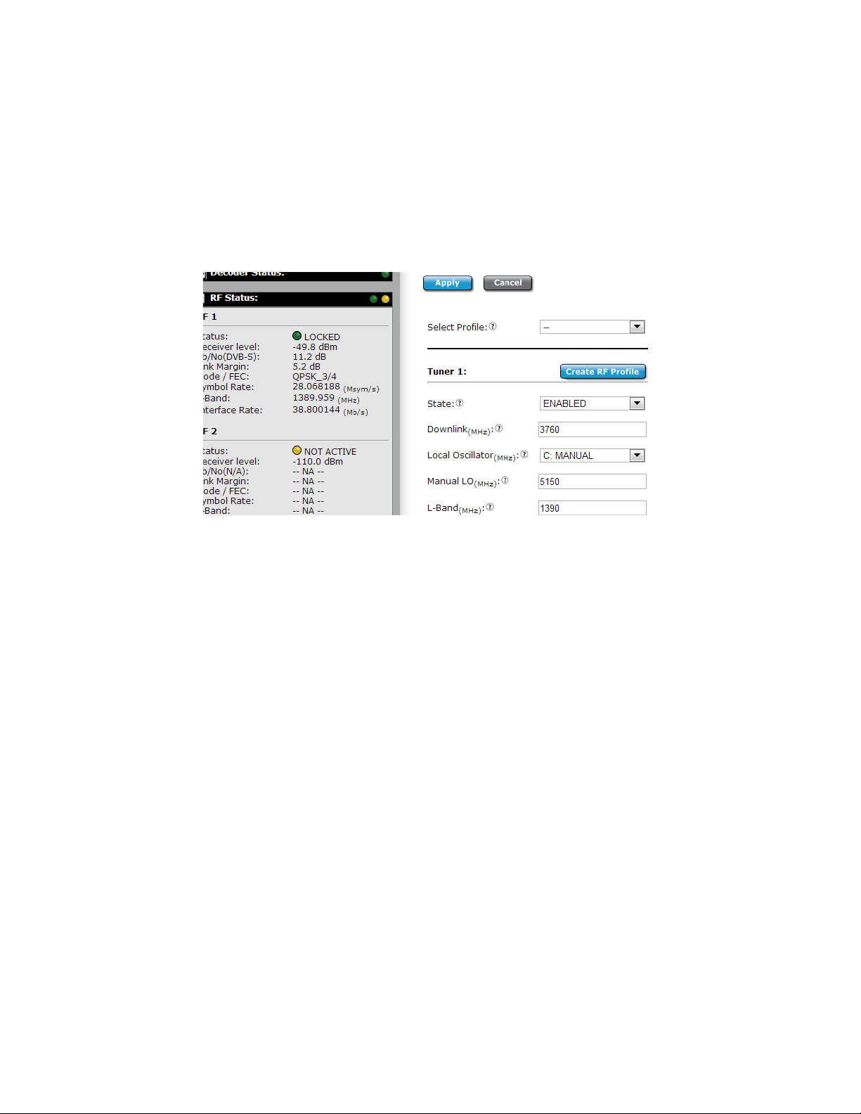
● Click the Apply button to save information to the currently running configuration
● Click the ‘Create RF Profile’ button next to the respective tuner that is desired to be
stored.
● Name the RF Profile and click OK. Please note that only Alphanumeric and
underscores are allowed in the profile name. If Spaces “ “, Dashes “-”, or other
special characters are entered, an error window will pop up.
● All drop downs will populate with the created RF profile name
To load a profile:
● Select an RF profile from the ‘Select Profile’ list above the desired tuner.
● After selection, the profile will be “previewed” and all configuration fields will display
the contents of the profile.
● If the profile is desired to be loaded into the respective tuner, click the Apply button.
If the profile is not desired, the Cancel button may be clicked or the double dash
profile “--” may be selected to exit from preview mode. Exiting preview mode will
return to display the current running configuration.
Profile Management:
● The Manage RF Profiles box gives users the ability to Delete (Red X button) or
Download (Downward Yellow button) RF Profiles from the IRD.
● Select a Profile and click the Delete button to have the profile removed from the
device and all drop down boxes.
● Select a Profile and click the Download button to have the profile downloaded to your
PC.
● The standard Upload button next to the Logs and Thumbnail button may be used to
Upload a profile to other devices.
Page 49

UDP / RTP / FEC / TCP IP Rx
The RD-70 supports a number of IP based protocols for the reception of transport streams
via private and public networks. The RD-70 will automatically determine if an IP stream is
UDP, RTP, or a SMPTE-2022 FEC stream. TCP reception is a less common implementation
for transmission of broadcast transport streams, but has recently been added to the RD-70.
UDP ( User Datagram Protocol ) multicast/unicast streams are commonly used for broadcast
transport streams in local or private networks that contain little to no packet loss. UDP
offers no protection against dropped packets or packets received out of order (usually due
to packets taking a different amount of time to traverse network devices). Due to the low
reliability of UDP, it is NOT recommended to be used over the public internet or in
environments where the potential of packet loss, increased jitter, or out of order packets is
high. If packets are lost or received out of order, service anomalies will occur. The RD-70
supports up to 100Mbps when a 7 DVB Packet payload exists for each UDP packet.
RTP ( Real-time Transport Protocol ) is another type of multicast/unicast stream that is
better to use than UDP in some environments. RTP is built upon the building blocks of UDP,
but adds packet sequence identification. Packet sequencing gives a receiver the information
needed to detect and correct packets that were received ‘out of order’. RTP is highly
recommended when timely delivery of each consecutive packet may not be guaranteed.
The RD-70 supports up to 100Mbps when a 7 DVB Packet payload exists for each RTP
packet.
RTP + FEC or SMPTE-2022 is an additional method used in dealing with lost packets, where
RTP alone can only tolerate packets received out of order. FEC ( Forward Error Correction )
streams add overhead to the overall data rate, but add protection in case of a lost packet.
FEC ( detection and correction of lost packets ) adds latency and data overhead as opposed
to UDP where no protection mechanisms exist. The amount of packet redundancy and
overhead can be configured at the RTP/FEC transmitter. Each multicast/unicast FEC stream
is transmitted on base port N and two FEC streams are sent on N+2 and N+4 respectively.
Page 50
When receiving FEC streams behind firewalls, please bear in mind that two additional ports (
N+2 and N+4 ) must be allowed through for proper error recovery to occur. The RD-70
supports up to 45Mbps SMPTE-2022 when a 7 DVB Packet payload exists for each RTP
packet.
TCP ( Transmission Control Protocol ) support, a connection based protocol, has recently
been added at an attempt to overcome some of the fundamental limitations of UDP and RTP.
UDP and RTP are ‘one way street’ types of protocols where the transmitter sends data and
never knows if the data makes it to the destination. TCP streams generally have higher
latency ( takes longer to transmit data and verify data has been transmitted ), but are more
reliable because each packet is accounted for by the receiver. If a packet is lost, the
transmitter will be informed to re-transmit the packet. The transmitter and receiver
continue to communicate about the quality of the reception and attempt to adjust packet
delivery accordingly. The TCP mechanism when combined with large IP receive buffers can
be more forgiving with packet loss, jitter, and out of order packets. The RD-70 supports up
to 15 Mb/s when a 7 DVB Packet payload exists for each TCP packet. Multicast is not
supported with TCP streams.
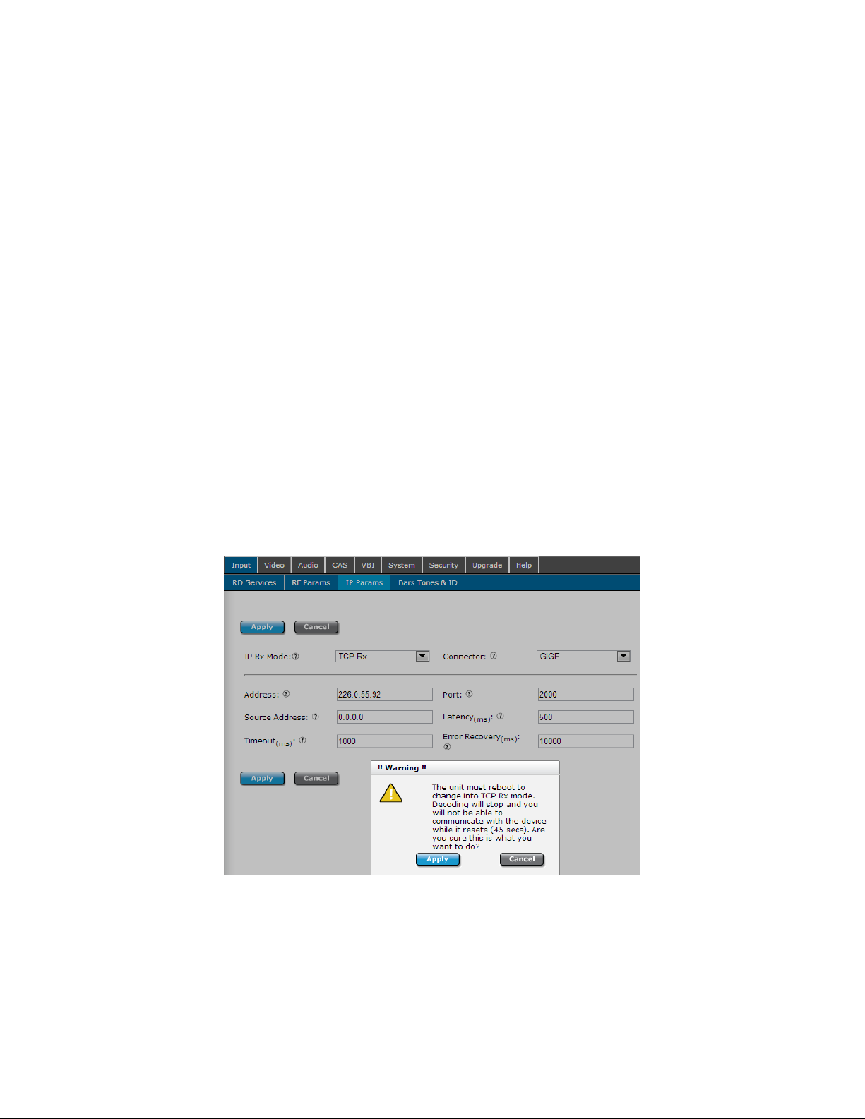
The RD-70 supports both unicast (point to point) and multicast (broadcast) streams. The
RD-70 operates in UDP/RTP mode by default. To setup an IP Rx session, first configure the
IP Rx operation mode. A unit reboot is required (WebUI asks for confirmation when
changing) when changing between UDP/RTP Rx and TCP Rx modes.
Multicast Reception - Address
To receive a multicast (UDP/RTP/SMPTE2022) stream, place the multicast address wished to
view in the ‘Address’ field. This address must match the same address used on the
multicast transmitter. Multicast IP address ranges are 224.xxx.xxx.xxx to 239.xxx.xxx.xxx,
Page 51

where 0 <= xxx <= 255. If you are new to multicast and attempting a first time connection,
226.0.1.1 is a common address to start with. Please verify transmitter address
configuration.
Optionally, the source specific multicast address (The actual IP address of the sending
device) may be entered for IGMPv3 applications. Configuring the Source Address will allow
multicasts to be received from the entered address and entered address only. This
configuration is non-functional for Unicasts. For IGMPv2 applications, the source address
recommendation is 0.0.0.0.
Unicast Reception - Address
To receive a unicast (TCP/UDP/RTP/SMPTE2022) stream, enter 0.0.0.0 in the ‘Address’ field.
The unit will be ‘listening’ for any streams sent directly to it. Refer to your IP transmitter
documentation for proper configuration of the transmitter.
Unicast/Multicast Reception
Enter the port number in the ‘port’ field. The port number must match the port number
used on the transmitter where the range is 0 to 65535. When 0, multicast is disabled. If
you are new to multicast and attempting a first time connection, 2000 is a common port to
start with. Please verify transmitter port configuration.
Choose the IP Rx ‘Connector’ dependent upon your network setup. Adtec recommends
using the GigE port for all IP receptions.
Once IP Rx is configured, click Apply.
Visit the Input -> Service tab and click the ‘Select first found’ radio button to enable IP
reception. IP service names will populate in the service list.
Page 52
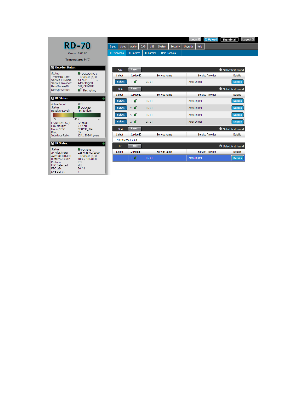
‘Select first found’ is also available via the Front Panel -> Services Menu -> Select First
configuration. Use the left/right arrows to select [IP], press select, then press enter to start
IP receiving.
Dolby E, Dolby D, LPCM, and Mpeg 1 Layer 2
As of 0.01.00 firmware, the RD-70 supports 16 channels of SDI embedded audio output
with support of up to four audio pass-throughs, up to 8 pairs (sixteen channels) of aligned
Mpeg 1 Layer 2 audio, and up to 8 pairs of Dolby Digital decoding. An audio pass-through
consists of a Dolby E 20 Bit, Dolby E 16 Bit, Dolby Digital, or a Linear PCM stream that is
preserved (not decoded) from the transport stream and embedded on the SDI output.
Mpeg 1 Layer 2 decode support includes 48kHz 32 - 384kbps. Interoperability support
includes stream type 0x03 (sometimes called Mpeg 1 Layer 2), stream type 0x04
(sometimes called Mpeg 2 Layer 2), PES aligned/unaligned audio, Mono ( with audio
duplication feature ), Dual Mono, and Stereo decoding.
Dolby Digital decode support includes a stereo output pair for each Dolby Digital Audio PID
assignment ( multi-channel Dolby Digital 5.1 for example is down-mixed to 2/0 ).
Page 53

Note: Encoder must support alignment for aligned audio feature.
The RD-70 automatically configures the audio engines upon acquisition of a program when
engines and sdi matrix are configured to ‘AUTO’. The audio is automatically output based
on ascending audio PID order from the selected program, not PMT order, to retain encoder
compatibilities. The left hand status panel of the Web UI shows current active SDI audio
output. Advanced configuration is available via the Audio tab for users that need to select
custom PID’s, disable audios, and duplicate audio pairs.
Dolby E line placement is handled automatically to meet Dolby Labs specification. Some
users may need custom line placement. If the customer Dolby E line placement selection is
out of specification, the RD will revert line placement to the automatic in range value.
Please see table in notes for Dolby E line placement recommendations.
Notes:
● Encoder must support alignment for aligned audio feature.
● Pass-through audio bit-rates are now displayed on the left hand status panel. Please
note that these are live calculated bit-rates and will not show a static number.
Dolby Labs - Dolby E recommended line position table
625251080i501080p50720p
50
Earliest 8 13 26 17 12 18 35 23
Ideal -80us 11 19 37 25 13 21 42 28
Ideal +- 80us 12 21 42 28 14 24 47 32
Ideal +80us 13 23 103 31 16 26 52 35
Latest 30 53 105 70 26 48 95 63
Adtec Auto 19 30 42 35 19 30 47 40
525
29.97
1080i
59.94
1080p
59.94
720p
59.94
AFD - Active Format Description
Active Format Description (AFD) contains aspect ratio and handling information utilized to
aid in picture presentation of downstream devices. This is used most often by downconverters and set top boxes.
AFD carriage can be carried within a transport stream as a unique ANC PID (ancillary pid),
within the video elementary stream as SEI data (H264), or user data (MPEG2). The RD-70
does not support AFD via an ANC PID at this time.
Page 54

The RD-70 AFD implementation preserves the native AFD code from the video elementary
stream and is inserted into the SDI ancillary data output. The SDI output is not modified in
anyway based upon this data. SDI line number for AFD carriage is configurable via the VBI
tab. The DID/SDID, AFD code, and aspect ratio flag can be seen in the VBI Output table via
the VBI tab.
Page 55

Genlock System
The RD-70 can synchronize its SDI and CVBS outputs to an external sync signal using the
SYNC IN input and the Genlock control system. The SYNC IN input signal's frame
synchronization is used to generate SDI and CVBS output pixel clocks, frame
synchronization and audio clocks that are locked to the SYNC IN reference. The video
decoder will automatically skip or repeat video frames as needed to adjust to differences
between the SYNC IN clock and the decoder source clock (which is synchronized to the
stream's PCR data). The audio system uses a sample rate converter to adjust to differences
between the decoder source clock and the SYNC IN clock.
The Genlock system will automatically cross lock for all resolutions within the 60 HZ
standard, all resolutions within the 59.94 Hz standards or all resolutions within the 50 Hz
standards. It does not cross lock between 50 HZ, 60 and 59.94 Hz standards at this time.
This allows the SYNC IN signal to be valid for compatible decoded streams (EG: An NTSC
black burst SYNC IN signal can be used to Genlock a 1080I59 feed).
The Genlock system can be configured in two modes. Genlock SLAVE mode is used when
the SYNC IN signal is synchronous with the decoded stream (both signals are using the
same 27 MHz source clock). This mode allows two RD-70's to be used for receiving 3D/4K
signals or when the decoded source is using the same clock base as the SYNC IN. This mode
bypasses the need for the audio sample rate converters. Genlock REMOTE mode is used
when the SYNC IN signal does not use the same 27 MHz clock source as the decoded
stream. This mode enables the audio sample rate converters for audio output.
The SYNC IN input will accept standard analog video sync for NTSC, PAL, 480I/P, 576I/P,
720P, and 1080I/P from Composite Video (CVBS). The input can accept Bi-level and Trilevel sync signals. The signal is processed to create synchronous audio and video clocks and
to frame align the SDI and CVBS outputs with the input sync signal. Generally, the output
will be automatically aligned within a few pixel clocks of the input.
If the Genlock system is locked, and the SYNC IN is removed, the system will attempt to
maintain the clocks and frame reference with the last known locked frequency. There may
be some clock drift over time. If the decoder is stopped and restarted in this mode, the
Genlock system will use the decode source clock and operate in a 'free-run' mode until the
reference is re-applied. The video and audio will be lost for a short time when the SYNC IN
reference is restored.
When the Genlock mode is changed, the Genlock system will automatically be reset. This
will cause a brief disturbance of the video and audio outputs.
Page 56

TS Out Decrypt
TSO or Transport Stream Out Decrypt is a newer feature of the RD product line that
determines how BISS encrypted transport streams are processed. This configuration
provides end users flexibility in how the RD is used. The TS Out Decrypt configuration
determines if the ASI output should mirror the selected input (OFF), thus preserving any
encrypted streams or if it should be decrypted / free to air (ON).
TS Out Decrypt should be set to OFF, the default configuration, if the IRD is to be used in a
confidence decode / turn around application. A confidence decode / turn around application
can involve the IRD being used a turn around device (IP to ASI or RF to ASI) where the user
wants to preserve encryption on the ASI output, but also wants to decode one of the
incoming programs. This configuration also allows the RD to ingest encrypted MPTS streams
that may be over the TSO limit. A sample diagram of how the transport stream is passed to
the ASI output through the system is shown below.
If the user wants to use the IRD as a decoder and decrypter, the TS Out Decrypt
configuration should be set to ON. All programs will be decrypted with the user supplied
BISS key and transported to the ASI output. This application is useful for users that want to
redistribute the stream to other non-BISS devices, such as transport stream analyzers or
third party decoders. Please note that when in this mode, total transport stream throughput
must not exceed the rate stated in the Technical Specifications found in Appendix B.
Page 57

Page 58

Chapter 4 - Appendix
Appendix A - GNU General Public License
Version 2, June 1991 Copyright (C) 1989, 1991 Free Software Foundation, Inc.
59 Temple Place, Suite 330, Boston, MA 02111-1307 USA
Everyone is permitted to copy and distribute verbatim copies of this license document, but
changing it is not allowed.
Preamble
The licenses for most software are designed to take away your freedom to share and change it. By contrast, the GNU General
Public License is intended to guarantee your freedom to share and change free software--to make sure the software is free for all its
users. This General Public License applies to most of the Free Software Foundation's software and to any other program whose
authors commit to using it. (Some other Free Software Foundation software is covered by the GNU Library General Public License
instead.) You can apply it to your programs, too.
When we speak of free software, we are referring to freedom, not price. Our General Public Licenses are designed to make sure
that you have the freedom to distribute copies of free software (and charge for this service if you wish), that you receive source code
or can get it if you want it, that you can change the software or use pieces of it in new free programs; and that you know you can do
these things.
To protect your rights, we need to make restrictions that forbid anyone to deny you these rights or to ask you to surrender the rights.
These restrictions translate to certain responsibilities for you if you distribute copies of the software, or if you modify it.
For example, if you distribute copies of such a program, whether gratis or for a fee, you must give the recipients all the rights that
you have. You must make sure that they, too, receive or can get the source code. And you must show them these terms so they
know their rights.
We protect your rights with two steps: (1) copyright the software, and (2) offer you this license which gives you legal permission to
copy, distribute and/or modify the software.
Also, for each author's protection and ours, we want to make certain that everyone understands that there is no warranty for this
free software. If the software is modified by someone else and passed on, we want its recipients to know that what they have is not
the original, so that any problems introduced by others will not reflect on the original authors' reputations.
Finally, any free program is threatened constantly by software patents. We wish to avoid the danger that redistributors of a free
program will individually obtain patent licenses, in effect making the program proprietary. To prevent this, we have made it clear that
any patent must be licensed for everyone's free use or not licensed at all.
The precise terms and conditions for copying, distribution and modification follow.
GNU GENERAL PUBLIC LICENSE TERMS AND CONDITIONS FOR COPYING, DISTRIBUTION AND MODIFICATION
0. This License applies to any program or other work which contains a notice placed by the copyright holder saying it may be
distributed under the terms of this General Public License. The "Program", below, refers to any such program or work, and a "work
based on the Program" means either the Program or any derivative work under copyright law: that is to say, a work containing the
Program or a portion of it, either verbatim or with modifications and/or translated into another language. (Hereinafter, translation is
included without limitation in the term "modification".) Each licensee is addressed as "you". Activities other than copying, distribution
and modification are not covered by this License; they are outside its scope. The act of running the Program is not restricted, and
the output from the Program is covered only if its contents constitute a work based on the Program (independent of having been
made by running the Program). Whether that is true depends on what the Program does.
1. You may copy and distribute verbatim copies of the Program's source code as you receive it, in any medium, provided that you
conspicuously and appropriately publish on each copy an appropriate copyright notice and disclaimer of warranty; keep intact all the
notices that refer to this License and to the absence of any warranty; and give any other recipients of the Program a copy of this
License along with the Program. You may charge a fee for the physical act of transferring a copy, and you may at your option offer
warranty protection in exchange for a fee.
2. You may modify your copy or copies of the Program or any portion of it, thus forming a work based on the Program, and copy
and distribute such modifications or work under the terms of Section 1 above, provided that you also meet all of these conditions:
a) You must cause the modified files to carry prominent notices stating that you changed the files and the date of any change.
b) You must cause any work that you distribute or publish, that in whole or in part contains or is derived from the Program or any
part thereof, to be licensed as a whole at no charge to all third parties under the terms of this License.
c) If the modified program normally reads commands interactively when run, you must cause it, when started running for such
interactive use in the most ordinary way, to print or display an announcement including an appropriate copyright notice and a notice
Page 59

that there is no warranty (or else, saying that you provide a warranty) and that users may redistribute the program under these
conditions, and telling the user how to view a copy of this License. (Exception: if the Program itself is interactive but does not
normally print such an announcement, your work based on the Program is not required to print an announcement.)
These requirements apply to the modified work as a whole. If identifiable sections of that work are not derived from the Program,
and can be reasonably considered independent and separate works in themselves, then this License, and its terms, do not apply to
those sections when you distribute them as separate works. But when you distribute the same sections as part of a whole which is a
work based on the Program, the distribution of the whole must be on the terms of this License, whose permissions for other
licensees extend to the entire whole, and thus to each and every part regardless of who wrote it.
Thus, it is not the intent of this section to claim rights or contest your rights to work written entirely by you; rather, the intent is to
exercise the right to control the distribution of derivative or collective works based on the Program. In addition, mere aggregation of
another work not based on the Program with the Program (or with a work based on the Program) on a volume of a storage or
distribution medium does not bring the other work under the scope of this License.
3. You may copy and distribute the Program (or a work based on it, under Section 2) in object code or executable form under the
terms of Sections 1 and 2 above provided that you also do one of the following:
a) Accompany it with the complete corresponding machine-readable source code, which must be distributed under the terms of
Sections 1 and 2 above on a medium customarily used for software interchange; or,
b) Accompany it with a written offer, valid for at least three years, to give any third party, for a charge no more than your cost of
physically performing source distribution, a complete machine-readable copy of the corresponding source code, to be distributed
under the terms of Sections 1 and 2 above on a medium customarily used for software interchange; or,
c) Accompany it with the information you received as to the offer to distribute corresponding source code. (This alternative is
allowed only for noncommercial distribution and only if you received the program in object code or executable form with such an
offer, in accord with Subsection b above.)
The source code for a work means the preferred form of the work for making modifications to it. For an executable work, complete
source code means all the source code for all modules it contains, plus any associated interface definition files, plus the scripts
used to control compilation and installation of the executable. However, as a special exception, the source code distributed need not
include anything that is normally distributed (in either source or binary form) with the major components (compiler, kernel, and so on)
of the operating system on which the executable runs, unless that component itself accompanies the executable.
If distribution of executable or object code is made by offering access to copy from a designated place, then offering equivalent
access to copy the source code from the same place counts as distribution of the source code, even though third parties are not
compelled to copy the source along with the object code.
4. You may not copy, modify, sublicense, or distribute the Program except as expressly provided under this License. Any attempt
otherwise to copy, modify, sublicense or distribute the Program is void, and will automatically terminate your rights under this
License. However, parties who have received copies, or rights, from you under this License will not have their licenses terminated
so long as such parties remain in full compliance.
5. You are not required to accept this License, since you have not signed it. However, nothing else grants you permission to modify
or distribute the Program or its derivative works. These actions are prohibited by law if you do not accept this License. Therefore, by
modifying or distributing the Program (or any work based on the Program), you indicate your acceptance of this License to do so,
and all its terms and conditions for copying, distributing or modifying the Program or works based on it.
6. Each time you redistribute the Program (or any work based on the Program), the recipient automatically receives a license from
the original licensor to copy, distribute or modify the Program subject to these terms and conditions. You may not impose any
further restrictions on the recipients' exercise of the rights granted herein. You are not responsible for enforcing compliance by third
parties to this License.
7. If, as a consequence of a court judgment or allegation of patent infringement or for any other reason (not limited to patent issues),
conditions are imposed on you (whether by court order, agreement or otherwise) that contradict the conditions of this License, they
do not excuse you from the conditions of this License. If you cannot distribute so as to satisfy simultaneously your obligations under
this License and any other pertinent obligations, then as a consequence you may not distribute the Program at all. For example, if a
patent license would not permit royalty-free redistribution of the Program by all those who receive copies directly or indirectly
through you, then the only way you could satisfy both it and this License would be to refrain entirely from distribution of the Program.
If any portion of this section is held invalid or unenforceable under any particular circumstance, the balance of the section is
intended to apply and the section as a whole is intended to apply in other circumstances. It is not the purpose of this section to
induce you to infringe any patents or other property right claims or to contest validity of any such claims; this section has the sole
purpose of protecting the integrity of the free software distribution system, which is implemented by public license practices. Many
people have made generous contributions to the wide range of software distributed through that system in reliance on consistent
application of that system; it is up to the author/donor to decide if he or she is willing to distribute software through any other system
and a licensee cannot impose that choice. This section is intended to make thoroughly clear what is believed to be a consequence
of the rest of this License.
8. If the distribution and/or use of the Program is restricted in certain countries either by patents or by copyrighted interfaces, the
original copyright holder who places the Program under this License may add an explicit geographical distribution limitation
excluding those countries, so that distribution is permitted only in or among countries not thus excluded. In such case, this License
incorporates the limitation as if written in the body of this License.
9. The Free Software Foundation may publish revised and/or new versions of the General Public License from time to time. Such
new versions will be similar in spirit to the present version, but may differ in detail to address new problems or concerns. Each
version is given a distinguishing version number. If the Program specifies a version number of this License which applies to it and
Page 60

"any later version", you have the option of following the terms and conditions either of that version or of any later version published
by the Free Software Foundation. If the Program does not specify a version number of this License, you may choose any version
ever published by the Free Software Foundation.
10. If you wish to incorporate parts of the Program into other free programs whose distribution conditions are different, write to the
author to ask for permission. For software which is copyrighted by the Free Software Foundation, write to the Free Software
Foundation; we sometimes make exceptions for this. Our decision will be guided by the two goals of preserving the free status of all
derivatives of our free software and of promoting the sharing and reuse of software generally.
NO WARRANTY
11. BECAUSE THE PROGRAM IS LICENSED FREE OF CHARGE, THERE IS NO WARRANTY FOR THE PROGRAM, TO THE
EXTENT PERMITTED BY APPLICABLE LAW. EXCEPT WHEN OTHERWISE STATED IN WRITING THE COPYRIGHT HOLDERS
AND/OR OTHER PARTIES PROVIDE THE PROGRAM "AS IS" WITHOUT WARRANTY OF ANY KIND, EITHER EXPRESSED OR
IMPLIED, INCLUDING, BUT NOT LIMITED TO, THE IMPLIED WARRANTIES OF MERCHANTABILITY AND FITNESS FOR A
PARTICULAR PURPOSE. THE ENTIRE RISK AS TO THE QUALITY AND PERFORMANCE OF THE PROGRAM IS WITH YOU.
SHOULD THE PROGRAM PROVE DEFECTIVE, YOU ASSUME THE COST OF ALL NECESSARY SERVICING, REPAIR OR
CORRECTION.
12. IN NO EVENT UNLESS REQUIRED BY APPLICABLE LAW OR AGREED TO IN WRITING WILL ANY COPYRIGHT HOLDER,
OR ANY OTHER PARTY WHO MAY MODIFY AND/OR REDISTRIBUTE THE PROGRAM AS PERMITTED ABOVE, BE LIABLE
TO YOU FOR DAMAGES, INCLUDING ANY GENERAL, SPECIAL, INCIDENTAL OR CONSEQUENTIAL DAMAGES ARISING
OUT OF THE USE OR INABILITY TO USE THE PROGRAM (INCLUDING BUT NOT LIMITED TO LOSS OF DATA OR DATA
BEING RENDERED INACCURATE OR LOSSES SUSTAINED BY YOU OR THIRD PARTIES OR A FAILURE OF THE PROGRAM
TO OPERATE WITH ANY OTHER PROGRAMS), EVEN IF SUCH HOLDER OR OTHER PARTY HAS BEEN ADVISED OF THE
POSSIBILITY OF SUCH DAMAGES.
END OF TERMS AND CONDITIONS
How to Apply These Terms to Your New Programs
If you develop a new program, and you want it to be of the greatest possible use to the public, the best way to achieve this is to
make it free software which everyone can redistribute and change under these terms.
To do so, attach the following notices to the program. It is safest to attach them to the start of each source file to most effectively
convey the exclusion of warranty; and each file should have at least the "copyright" line and a pointer to where the full notice is
found.
<one line to give the program's name and a brief idea of what it does.> Copyright (C) <year> <name of author>
This program is free software; you can redistribute it and/or modify it under the terms of the GNU General Public License as
published by the Free Software Foundation; either version 2 of the License, or (at your option) any later version.
This program is distributed in the hope that it will be useful, but WITHOUT ANY WARRANTY; without even the implied warranty of
MERCHANTABILITY or FITNESS FOR A PARTICULAR PURPOSE. See the GNU General Public License for more details.
You should have received a copy of the GNU General Public License along with this program; if not, write to the Free Software
Foundation, Inc., 59 Temple Place, Suite 330, Boston, MA 02111-1307 USA
Also add information on how to contact you by electronic and paper mail.
If the program is interactive, make it output a short notice like this when it starts in an interactive mode:
Gnomovision version 69, Copyright (C) year name of author Gnomovision comes with ABSOLUTELY NO WARRANTY; for details
type `show w'. This is free software, and you are welcome to redistribute it under certain conditions; type `show c' for details.
The hypothetical commands `show w' and `show c' should show the appropriate parts of the General Public License. Of course, the
commands you use may be called something other than `show w' and `show c'; they could even be mouse-clicks or menu items-whatever suits your program.
You should also get your employer (if you work as a programmer) or your school, if any, to sign a "copyright disclaimer" for the
program, if necessary. Here is a sample; alter the names:
Yoyodyne, Inc., hereby disclaims all copyright interest in the program `Gnomovision' (which makes passes at compilers) written by
James Hacker. <signature of Ty Coon>, 1 April 1989 Ty Coon, President of Vice
This General Public License does not permit incorporating your program into proprietary programs. If your program is a subroutine
library, you may consider it more useful to permit linking proprietary applications with the library. If this is what you want to do, use
the GNU Library General Public License instead of this License.
Page 61

Appendix B - Technical Specifications
Base Model (RD70-XX)
Inputs
DVB-ASI
Use: Input available for Decode or Pass to ASI outputs.
Standard: Asynchronous Serial Interface per EN500083-9
Input Rates: DVB-ASI 210Mb/s for free-to-air 188/204/208 Byte Transport streams (SPTS and MPTS).
If TSO (TS Out Decrypt) option is OFF and transport stream contains BISS encrypted programs, up to
164Mb/s at this time. If TSO option is ON and transport stream contain BISS encrypted programs
(SPTS and MPTS), up to 120Mb/s. See TSO article in Chapter 3 for more information.
Connector: BNC (75 Ohm)
IP
Use: Input available for decode, but may also be used for control
Standard: MPEG 2 RTP v2 transport (RFC 3550)
Input Rates: 1 - 100Mbps (188 byte DVB packet size, 7 per IP packet)*
Standard: MPEG 2 UDP transport
Input Rates: 1 - 100Mbps (188 byte DVB packet size, 7 per IP packet)*
Standard: RTP SMPTE 2022-1 2007 FEC
Input Rates: 1 - 45Mbps (188 byte DVB packet size, 7 per IP packet)*
Connection speed: GigE (100/1000BaseT)
*Supported bandwidth decreases with streams that have not been created with 7 DVB packets per IP
packet. 1 DVB Packet per IP Packet does not utilize the same data efficiency / throughput as 7. The
amount of DVB packets per IP payload is a multicast transmitter configuration and is automatically
detected by the receiver. To utilize full IP receive throughput, use of the GigE port with packetization
of 7 DVB packets per IP packet is recommended.
**The user has the ability to receive IP streams via the GigE or 10/100 management port. When
receiving streams via the 10/100 management port, throughput is limited.
Connector: 8 pin RJ45
RF (optional)
Use: Input available for decode.
Standard: DVBS & DVB-S2 QPSK/8PSK with 16APSK and 32APSK options available.
188/204/208 byte packet size
Connector: Two Female F connectors (75 Ohm)
Outputs
3G-SDI / HD-SDI / SD-SDI
Two banks (two mirrored SDI outputs per bank) of SDI Outputs from Decoder
Standard: Video & Audio SMPTE 259M - SD, SMPTE 292M - HD, SMPTE 424M - 3G
Up to 16 Channels of Embedded audio
SDI Ancillary support for Closed Captioning, AFD and Teletext
Page 62

SDI Ancillary data and OSD overlay have unique configuration for each SDI bank
Connector: Three BNC (75 Ohm), One SFP
note*: 3G-SDI Outputs have selectable Level A and Level B Dual Link output control to
retain interoperability with other third party 3G devices. The default mapping level is Level
A.
CVBS
SD NTSC or PAL D1 Composite Video Output (downscaled from HD source)
Supports Closed Captioning and Teletext
Connector: BNC (75 Ohm)
DVB-ASI
Standard: Asynchronous Serial Interface per EN500083-9
ASI Mirrored from DVB-ASI Input, IP Input, or RF Input with purchase of optional tuner package. All
streams are output as 188 byte packets.
Connector: Three BNC (75 Ohm)
AES Audio
Standard: AES3
8 pairs of decoded audio
Connector: Eight BNC (75 Ohm)
Analog Audio
Two balanced pairs via DB9 connector. (1 pair per DB9)
+18dBu nominal clipping level, -40 to +18dBu selectable.
Connector: Two DB9 (600 Ohm)
Communications
COM2 Serial Port
Use: API Serial Communication Interface
Default Baud Configuration: 38,400bps 8 data bits 1 stop bit no parity
Connector: 8 pin RJ45
COM1 Serial Port
Use: Serial Port Used for Troubleshooting (Terminal)
Connector: 8 pin RJ45 (supplied with DB9 to RJ45 adapter)
Baud Configuration: 115,200 bps 8 data bits 1 stop bit no parity
Ethernet Port
Use: ethernet port used for network control, but can be used for IP receive
Format: Ethernet 10/100BaseT
Communication Methods: WebUI, SNMP, Telnet, XCP
Connector: 8 pin RJ45
DB9 Parallel Port
Use: DB9 parallel port used for custom triggering / integration
Connector: DB9 Male
Page 63

GPIO Port
Use: not used as this time
Connector: DB9 Male
Video and Audio
Video Decode
MPEG-2 SD (ISO/IEC 13818-2) Decode:
Format: 480i59.94, 576i50
Profiles: MP@ML, SP@ML, 422P@ML
MPEG-2 HD (ISO/IEC 13818-2) Decode:
Format: 720p50, 720p59.94, 1080i50, 1080i59.94
Profiles: 422P@HL, MP@H14L, MP@HL, SP@H14L, SP@HL
MPEG-4 SD (ISO/IEC 14496-10) Decode:
Format: 480i59.94, 576i50
Profiles: Baseline, Main (support 8 bits only)
MPEG-4 HD (ISO/IEC 14496-10) Decode:
Format: 720p50, 720p59.94, 1080i50, 1080i59.94, 1080p50, 1080p59.94
Profiles: High, High422 (support 8 bit and 10 bit)
Max Level: 4.1-4.2 (CABAC:50Mbps, CAVLC:150Mbps)
Supported tools support Baseline except ASO, FMO
Audio Decode
MPEG 1 Layer 2 audio (8 pairs)
AAC-LC Stereo and Surround Decode (2 sets of 3 pairs) *requires feature key
Dolby Digital AC3 stereo downmix (8 pairs) *requires feature key
Audio Pass-through
Supports up to two Dolby-E 16/20 bit, Dolby Digital AC3 16 bit, and/or Linear PCM 16/20/24 bit passthrough sessions. 24 bit input samples are truncated to 20 bits. Each SDI output contains all active
pass-through sessions.
Physical and Operational
Physical / Environmental
1 RU - 18D X 19W X 1.65H
Weight – 9-14lbs. Dependent on RF Option
Power
Input Voltage: 100VAC - 240VAC 50/60Hz
Operational
- Ambient operating temperature: -20C to 40C.
- Ambient storage temperature: -30C to 80C.
- Non-condensing relative humidity range: 30% to 85%
Page 64

Certification / Compliance
RoHS Compliant
Advanced Demodulator (ADV option)
note: Software keys are required to unlock full hardware support.
Modulation Scheme support: QPSK / 8PSK / 16APSK
DVB-S2 symbol rate range: 1 - 45Msym/s
DVB-S symbol rate range: 1 - 45Msym/s
frequency range: 950 - 2150MHz
min. input level: -70dBm
max. input level: -25dBm
Carrier acquisition Range: up to 7.5MHz
( if symbol rate < 5Msym/s: 1.5 x baudrate . if symbol rate > 5Msym/s: 7.5MHz)
LNB Power and Control:
11.5 - 14V ( vertical polarisation)
16 - 19V ( horizontal polarisation)
22kHz ± 4kHz (band selection according to universal LNB for ASTRA satellites)
Page 65

L-Band Demodulator (LB option)
note: Software keys are required to unlock full hardware support.
RF Inputs: Dual RF inputs capable of simultaneous lock
EN 302 207 and EN 300 421 compliant for single and multi-stream
Modulation Scheme support: QPSK / 8PSK / 16APSK / 32APSK
Long and Short frame support
Supported Roll-off: 5%, 10%, 15%, 20%, 25%, 35%
Supported Code Rates:
DVB-S QPSK: 1/2, 3/5, 2/3, 3/4, 5/6, 7/8
DVB-S2 QPSK: 1/4, 1/3, 2/5, 1/2, 3/5, 2/3, 3/4, 4/5, 5/6, 8/9, 9/10
DVB-S2 8PSK: 3/5, 2/3, 3/4, 5/6, 8/9, 9/10
DVB-S2 16APSK: 2/3, 3/4, 4/5, 5/6, 8/9, 9/10
DVB-S2 32APSK: 3/4, 4/5, 5/6, 8/9, 9/10
DVB-S symbol rate range: Up to 62Msym/s*
DVB-S2 symbol rate range: 1 - 65Msym/s (QPSK / 8PSK / 16APSK / 32APSK)*
frequency range: 950 - 2150MHz
min. input level: -65dBm**
max. input level: -25dBm**
LNB Power and Control:
13V (vertical polarisation)
18V (horizontal polarisation)
22kHz (band selection according to universal LNB for ASTRA satellites)
**input level dependent on function of MODCOD and baudrate
* Maximum supported baud rate is dependent on both tuners active state. One must be disabled to
achieve maximum symbol rate capabilities. View table below for symbol rate capabilities.
Modulation Single Tuner (Msym/s) Dual Tuner (Msym/s)
QPSK 65 65
8PSK 65 45
16APSK 65 33
32APSK 54 27
Page 66

Premium Demodulator (PRM option)
note: Software keys are required to unlock full hardware support.
Modulation Scheme support: QPSK / 8PSK / 16APSK / 32APSK
Supported Roll-off: 5%, 10%, 15%, 20%, 25%, 35%
Supported Code Rates:
DVB-S QPSK: 1/2, 2/3, 3/4, 5/6, 6/7, 7/8
DVB-S 8PSK: 2/3, 5/6, 8/9
DVB-S/SNG 16QAM: 3/4, 7/8, (AUTO)
DVB-S2 QPSK: 1/4, 1/3, 2/5, 1/2, 3/5, 2/3, 3/4, 4/5, 5/6, 8/9, 9/10
DVB-S2 8PSK: 3/5, 2/3, 3/4, 5/6, 8/9, 9/10
DVB-S2 16APSK: 2/3, 3/4, 4/5, 5/6, 8/9, 9/10
DVB-S2 32APSK: 3/4, 4/5, 5/6, 8/9, 9/10
DVB-S symbol rate range: 1 - 45 Mbaud
DVB-S2 symbol rate range: 0.256 - 45Mbaud (QPSK / 8PSK / 16APSK)
DVB-S2 symbol rate range 1 - 33Mbaud (32APSK, normal frames only)
frequency range: 950 - 2150MHz
min. input level: -70dBm
max. input level: -25dBm
Carrier acquisition Range: up to 7.5MHz
( if symbolrate < 5 Mbaud: 1.5 x baudrate . if symbol rate > 5 Mbaud: 7.5MHz)
LNB Power and Control:
11.5 - 14V (vertical polarisation)
16 - 19V (horizontal polarisation)
22kHz ± 4kHz (band selection according to universal LNB for ASTRA satellites)
Page 67

Appendix C - Adtec Digital Support & Service
Technical Support and Customer Service includes troubleshooting product/system functional
operations concerning Adtec equipment, embedded systems and single device issues; Service Order
generation, processing and tracking; Warranty claim processing; and on-site system evaluation and
maintenance. Technical Support plans do not include customer training programs. Programs
incorporating customer training are defined in the Training Services Policy. Customer Services
technicians provide limited instruction during a support call/email/fax in order to facilitate checking for
proper equipment operation.
Telephone and Email Support
● Telephone: 615-256-6619 ext. 166
● Email: support@adtecinc.com
● Internet: http :// adtecdigital . com / support / support - request
Adtec Digital offers telephone, email and fax support, warranty and service related inquiries
during normal business hours: 9:00am to 5:00pm Central Standard Time (CST), Monday through
Friday, holidays excepted. Support Requests can also be submitted on-line.
All inquiries will be processed in the order in which they are received and by the criteria outlined in the
Call Response Order. Inquiries and inquiry responses made after 5:00 PM (CST) weekdays, Saturday,
Sunday or on an Adtec-recognized holiday will be processed the next business day in the order
received.
Callers on hold and returned calls will be prioritized by the following criteria:
● Priority-24 Subscription Customers
● Standard-Priority Subscription Customers
● All customers that have purchased Installation & Training, within 90 days of the installation.
● Adtec Certified Operators (ACO)
● Limited Level Support, Warranty & Service Requests
● Multi-device system installations that have purchased Installation & Training from Adtec
● Distributors
● System Integrators
● Multi-device systems
● Single device users
Preparing for Support
To help expedite the troubleshooting process, please be prepared to provide the following
information to the support representative:
● Product(s) affected: Please provide a list of the Adtec Products involved including the
Revision Number for each affected product.
● Description of the Problem: Please include a detailed description of the problem. Include
the approximate time and day the problem occurred, the spot ID of the material being
inserted and what the operator reported about the incident. It is also helpful to note any
recent changes to the system. More information is always better than too little information.
● Your Contact Data: Please include contact information so we can reach you to discuss how to
fix the problem, additional troubleshooting steps that are required or to gather more complete
Page 68

information regarding the problem. Please include your facility name (or call letters), your
name, title, email address, telephone number, hours of work, and other contact persons if you
are not available.
SLA Options
Effective January 1, 2014
For questions, please email slaquestions @ adtecinc . com
● SLA STANDARD*
Services: Includes initial product orientation
Technical support M-F 8AM-8PM (EST)
Firmware and software upgrades
Includes repair expenses**
Includes ground shipping within US
International shipping is extra
Fees: Free for one year after purchase
● SLA PRIORITY 24*
Services: SLA Extended Warranty plus…
Technical support 24x7x365
Expedited shipping is extra
● SLA PREMIUM 24*
Services: SLA Priority 24 plus…
Next business day advance loaners
● SLA EXTENDED WARRANTY*
Services: Extends warranty after year one
Includes repair expenses
Expedited shipping is extra
● SLA LEGACY
Services: Includes initial product orientation
Technical support M-F 8AM - 8PM (EST)
Firmware and software upgrades
Includes Duet, Soloist 2/ 2S, Mirage, edje1013/1015/2000/2100/2110.
Most legacy products cannot be repaired
● SLA SESSION SUPPORT
Services: Technical support M-F 8AM - 8PM (EST)
Includes support for 5 days after first call
● SE SUPPORT
Services: Event based on-site technical representation
*Available for up to three years after purchase for Adtec manufactured products only
**Excludes equipment that has been subject to misuse, negligence, or accident
All SLAs are subject to terms and conditions of sale. For details see adtecdigital.com/sales/terms
 Loading...