

Page 1

EN-30
Dual Channel Capable HD/SD MultiCODEC DSNG Encoder
w/ optional IF/LB/10Mhz Modulation
USER GUIDE
2/20/15 - 1.02.01
Page 2

Table of Contents
Table of Contents
Trademarks & Copyrights
Electrical Device Compliance Notices
Safety Warnings and Cautions
Compliance Notices
FCC
Industry Canada
European Union EMC Directive Conformance Statement
Chapter 1 - Product Overview
Product Introduction
Chapter 2 - Getting Started
Front Panel
Panel Diagram
Model Indicator Decals
Front Panel LCD Quick Views
Transport LED Indicators - Channel 1 & 2
Audio Encode Indicators - Channel 1 & 2
System Indicators
Controls
Modulator Lineup
Front Panel Menu Structure
Services Menu
RF Tx Menu
IP Tx Menu
Video Menu
Audio Menu
PIDs Menu
VBI Menu
Profile Menu
CAS Menu
System Menu
Login
Duration
Backlight Dim Delay
Network Sub Menu
Time Sub Menu
NTP Sub Menu
Alarm
SNMP Sub Menu
Com 2
Feature Sub Menu
Name
Page 3

Firmware
Back Panel Diagram
Processor Connectors
Video / Audio Inputs
Output
Chapter 3 - Using the Web Application
Introduction
Logging In
Upgrading your device
Chapter 4 - How - To Guides
How to Complete a Manual Upgrade
How to Connect via Telnet
How to Connect via FTP
How to Use API Commands
How Video Rates are Configured
( Example is pertinent to MPEG 2 ( VE 1))
How to enable EAS mode
EAS GPIO Connector Pinout
How to configure Network EAS Triggering
How passthru audio function - Dolby E / 5.1 / 2.0, Dolby D , LPCM
Common Passthru Problems :
How to use ASI Remux
EN - XX ASI Remux with Manual PID Mapping
Vertical Interval Time Code
Chapter 5 - Appendix
Appendix A - GNU General Public License
Appendix B - Technical Specifications
EN 30- VE 1-01 Video Specs ( MPEG 2):
EN 30- VE 2-01 Video Specs ( AVC ):
IF , L - Band Modulator + 10 MHz ( option ) - IF / LB /10 M -01
Appendix C - DB 9- M Analog audio input pinout
Appendix D - Adtec Digital Support & Service
Telephone and Email Support
Preparing for Support
SLA Options
Page 4

Trademarks & Copyrights
Copyright: (c) 2012-Present: Adtec Digital. All rights reserved. This document may not, in
whole or in part, be copied, photocopied, reproduced and translated, or reduced to any
electronic medium or machine-readable form without prior written consent from Adtec
Digital.
Trademarks: EN-30 is a trademark of Adtec Digital. Dolby, Dolby Digital, AC-3 and the
double-D symbol are registered trademarks of Dolby Laboratories. Other product and
company names may be trademarks or registered trademarks of their respective companies.
The information in this document is subject to change without notice.
Page 5

Electrical Device Compliance Notices
Safety Warnings and Cautions
For your safety and the proper operation of the device:
● This unit must be installed and serviced by suitably qualified personnel only.
● Do not break the warranty seals on the device or open the lid. Only approved service
technicians are permitted to service this equipment.
● Disconnect all power before servicing the unit.
● Do not expose this device to rain or other moisture. Clean only with a dry cloth.
● If not installed in an equipment rack, install the product securely on a stable surface.
● Install the product in a protected location where no one can step or trip over the
supply cord, and where the supply cord will not be damaged.
● If a system is installed in a closed or multi-unit rack assembly, the operating ambient
temperature of the rack environment may be greater than the room ambient
temperature.
● Consideration should be given to installing the unit in an environment compatible
with the maximum recommended ambient temperature of 50 degrees Celsius (122
degrees Fahrenheit).
● Install the unit in a rack so that the amount of airflow required for safe operation is
not compromised.
○ The recommended clearance on the top and sides of the unit is at least ½ “
(one half inch/one centimeter).
● Mounting of the unit in a rack should be such that no hazardous condition is achieved
due to uneven mechanical loading.
● Use only a grounded electrical outlet when connecting the unit to a power source.
● Reliable earth grounding of rack-mount equipment should be maintained.
○ Particular attention should be given to supply connection other than direct
connections to the branch circuit (e.g., use of power strips).
Page 6

Compliance Notices
FCC
Note: This equipment has been tested and found to comply with the limits for a Class B
digital device, pursuant to Part 15 of the FCC Rules. These limits are designed to provide
reasonable protection against harmful interference in a residential installation. This
equipment generates, uses and can radiate radio frequency energy and, if not installed and
used in accordance with the instructions, may cause harmful interference to radio
communications. However, there is no guarantee that interference will not occur in a
particular installation. If this equipment does cause harmful interference to radio or
television reception, which can be determined by turning the equipment off and on, the user
is encouraged to try to correct the interference by one or more of the following measures:
● Reorient or relocate the receiving antenna.
● Increase the separation between the equipment and receiver.
● Connect the equipment into an outlet on a circuit different from that to which the
receiver is connected.
● Consult the dealer or an experienced radio/TV technician for help.
Warning: Changes or modifications to this device not expressly approved by Adtec Digital
could void the user’s authority to operate the equipment.
Industry Canada
This Class B digital apparatus meets all requirements of the Canadian Interference
Causing Equipment Regulations. Operation is subject to the following two conditions:(1) this
device may not cause harmful interference, and (2) this device must accept any interference
received, including interference that may cause undesired operation.
Cet appareillage numérique de la classe B répond à toutes les exigences de l'interférence
canadienne causant des règlements d'équipement. L'opération est sujette aux deux
conditions suivantes: (1) ce dispositif peut ne pas causer l'interférence nocive, et (2) ce
dispositif doit accepter n'importe quelle interférence reçue, y compris l'interférence qui peut
causer l'opération peu désirée.
European Union EMC Directive Conformance Statement
This product is in conformity with the protection requirements of EU Council Directive
2004/108/EC on the approximation of the laws of the Member States relating to
electromagnetic compatibility. Adtec Digital cannot accept responsibility for any failure to
satisfy the protection requirements resulting from a user modification of the product. This
product has been tested and found to comply with the limits for Class B Information
Technology Equipment according to CISPR 22 / EN 55022.
Page 7
Chapter 1 - Product Overview
Product Introduction
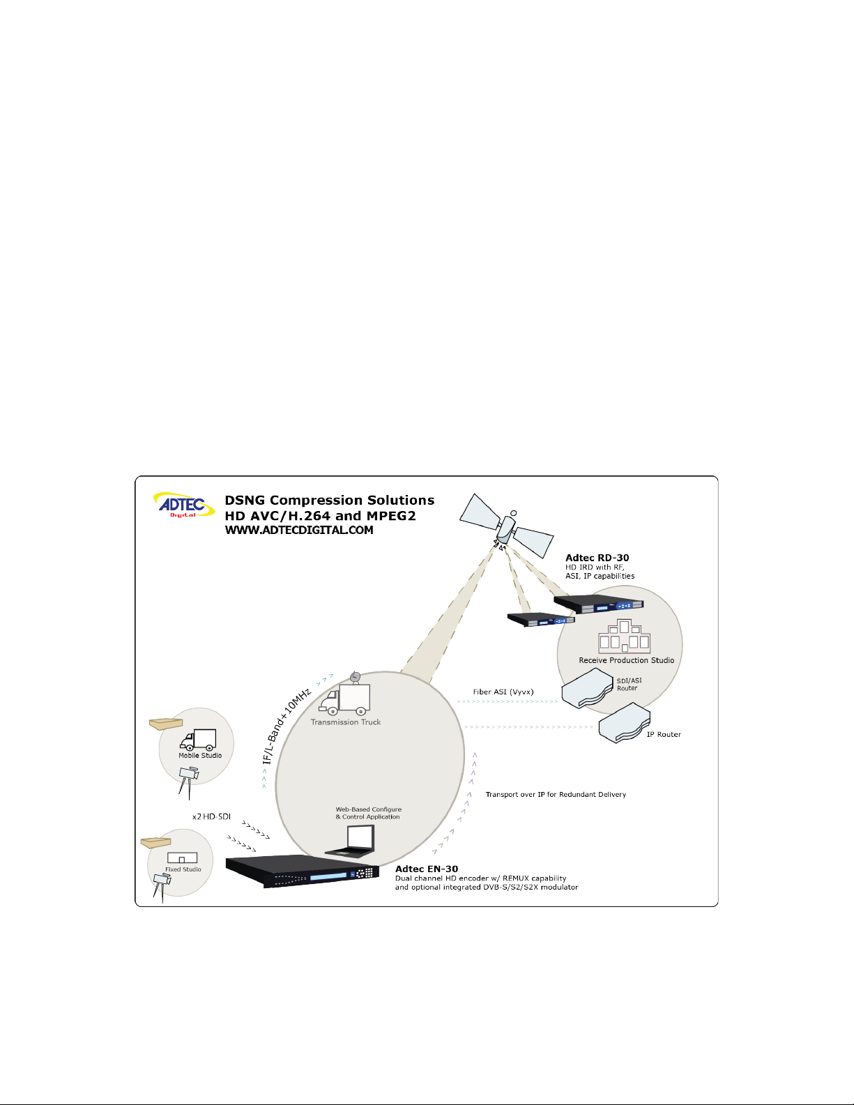
The EN30 is a two-channel High and Standard definition MPEG-2 or H.264 encoder
supporting ATSC and DVB tables through ASI and IP transport streams. The EN30 can be
ordered with optional satellite modulation for contribution and distribution applications.
It inherits Adtec’s broadcast quality compression, advanced feature set, service
performance, and reliability in the new dense two-channel platform targeted towards
broadcasters, cable and IP compression applications.
The device automatically detects video and audio from two sources (combination of
HD and SD acceptable), encodes, multiplexes and sends them back out as one combined TS
via IP, ASI or optional RF. VBI, CAS, and support for Emergency Alert (EAS) triggering are
standard.
Applications
Adtec Digital EN-30 and RD-30 contribution
Page 8
Chapter 2 - Getting Started
Front Panel
The Function Buttons and Directional Keypad of the EN-30 are used to configure and
monitor the signal input and output of the device.
Panel Diagram
Model Indicator Decals
Front Panel LCD Quick Views
There are 8 Quick Views that can be accessed by the front panel LCD by pressing
the up and down arrows.
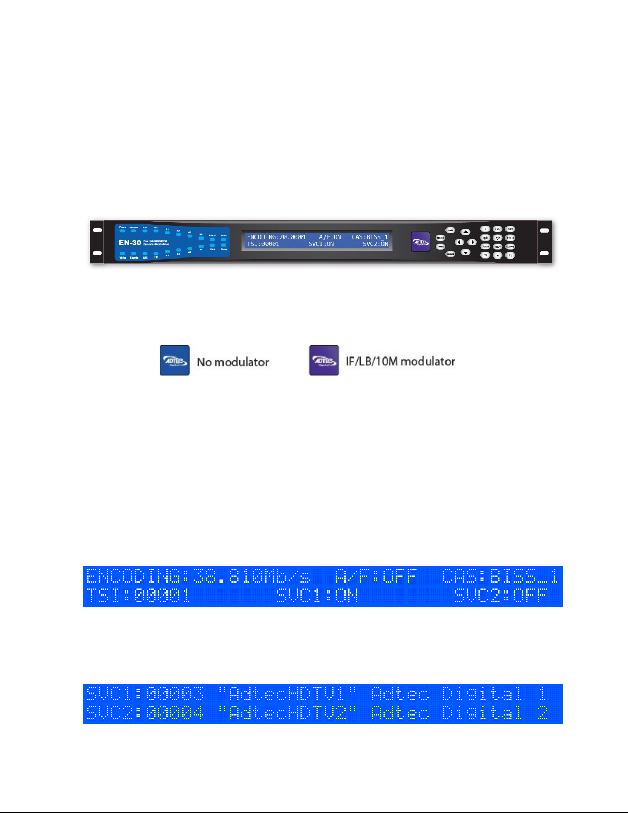
1) Encoding State: When in normal encoding mode, the LCD will display the following
information. Since there can be up to 2 encoders in the product, you can view the status of
both services. *When only one encoder module is present the second module statistics will
not be displayed*
2) Services State: This quick view displays the Service ID number, short name, and long
name for both encoder modules.
Page 9
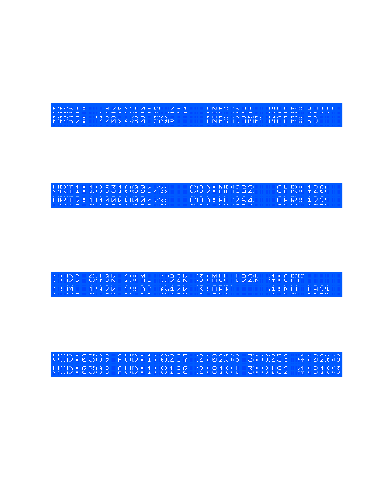
3) Video Input State: This quick view displays the resolution, input signal source, and
input signal mode for both encoder modules.
4) Video Encoding State: This quick view displays the Video Bit Rate, CODEC, and Chroma
type for both encoder modules.
5) Audio Encoding State: This quick view displays the type of Audio Encoding and the bit
rate for both encoder modules. Service 1 statistics are the first line of information. Service
2 statistics are the second line of information.
6) PID Statistics: This quick view displays the Video and Audio PIDs for both encoder
modules. Service 1 PIDs are the first line of information. Service 2 PIDs are the second
line of information.
7) TSoIP State: This quick view displays the status of IP Transport mode, RTP, FEC mode,
and number of selected services. Up to 4 destination IP addresses can be sent
simultaneously.
Page 10
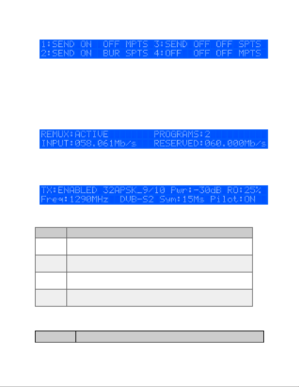
8) ASI Remux State: This quick view displays the status of ASI Remux status if the
feature is enabled.
9) *Modulator State: This quick view displays the status of RF Tx status if the unit is
equipped with optional modulator.
Transport LED Indicators - Channel 1 & 2
Indicator Function
Video On - Video is detected on the selected input.
Blink - No video is detected.
Encode Off - Device is not encoding. Idle State
On - Device is encoding.
AVC Off - MPEG 2 module installed.
On - MPEG 4 (H.264) module installed.
HD Off - Encoding standard definition.
On - Encoding high definition.
Audio Encode Indicators - Channel 1 & 2
Indicator Function
Page 11

A1 -A4 Off - Audio encoder configuration is set to off.
On - Audio encoder configuration is set to encode or passthru.
Blink - Audio pair is enabled but there is no payload on the input
System Indicators
Indicator Function
Alarm Off - No system alarms.
On - System alarm. (Typically NTP alarm)
BISS Off - No encryption set
On - Encryption active
Link Off - No network detected
On - Network communication active
Busy Off - No network activity
On - Network traffic present
Page 12

Controls
Using the Mode, Select, Enter, Escape, and directional buttons, the user can control the unit
via the front panel.
Control Function
Mode button Mode will cycle you through top layer menus.
Select Select will enter you into edit mode.
Enter Enter submits any edits.
Escape Escape returns you to the previous menu layer.
Cursor Arrows Arrows will navigate you within submenus
Programming
Keypad
For value entry. F2 functions as a “.” decimal or period.
Modulator Lineup
This feature enables the operator to quickly view and/or configure select modulator RF
output parameters. The parameters available in this menu are;
1. Carrier Mode: [ PURE_CARRIER or MODULATED]
2. Transmit: [ ENABLED or DISABLED]
3. Output Power: [ in 0.5dB increments ]
4. Output Frequency: [ in 1.0MHz increments ]
To access the menu, press the F1 and F2 keys simultaneously. The front panel will briefly
flash “MODULATOR LINEUP” then display the menu.
Note: To use this feature, the front panel display must be illuminated. If the display is
dim, press ANY front panel button to illuminate it.
Note: If the unit has been previously configured by the operator and powered OFF and ON,
then the display will read the last valid configuration, however, Tx will read DISABLED.
To select the desired Carrier Mode, press the front panel “SELECT” button.
To set Transmit to ENABLED or DISABLED, press the front panel “ENTER” button.
To set the desired output Power Level, press and hold the front panel ↑ or ↓ button.
To set the desired output Modulator Frequency, press and hold the front panel ← or →
button
Page 13

Note: If the Modulator Frequency is reconfigured when Transmit = ENABLED, then Transmit
will be automatically set to DISABLED.
Front Panel Menu Structure
Services Menu
The following diagram illustrates the structure and flow of the Services Menu on the Adtec
EN-30 device. TX MUX Rate, Table, and TSID are global configurations, while items under
the denoted << >> parallel menu are unique to each encoder :
Control Function Options API Command
TS MUX
Rate
Video
Autofill
Tables Configures the table generation standard to
TSID Transport Stream ID is a user-defined value
ASI Mode Configures the encoder to egress a constant
ASI
Remux
Configures the total transport multiplex rate.
*Controlled by modulator when set to
Enable
Video Autofill automatically adjust the Video
Bit Rate to occupy the maximum fill of the
TS Mux Rate
be used
in the PAT packet used to identify individual
transport streams
transport stream when video is not present.
It is recommended to keep ASI Mode set to
Continuous
Reserves the bandwidth needed for
incoming ASI transport stream
Note: Setting value to zero disables ASI
Remux
1 - 150
Mb/s
ON
OFF
DVB
ATSC
MPEG
0x0000 0xFFFF
ON
OFF
0-100
Mb/s
*.ECMD0 TMR
*.ECMD0 VAF
*.ECMD0 TON
*.ECMD0 TSI
*.ECMD0 ASM
*.ECMD0 TRS
ASI 0
Active Configure each encoding module to be
turned on or off
Service
Name
Service
Provider
Name of the program or event, carried in
the SDT table of a transport stream
Name of the party offering the program or
event, carried in the SDT table of a
transport stream
ON
OFF
text field;
20character
limit (incl.
spaces)
text field;
20character
limit (incl.
*.ECMD# STU
*.ECMD# SNA
*.ECMD# SPR
Page 14

spaces)
Service
Number
Logical
Channel
Number
The Service Number or Program Number in PAT
& PMT packets identifies which program is
associated with which Video & Audio PIDs. This
value should be entered in decimal format
This setting allows you to set the logical
channel number that will be used to tune in
with a set top box or television. This setting
1 - 65535
1 - 9999 *.ECMD# LCN
is only valid with DVB table generation.
Bars,
Tones, ID
Menu
Bars, Tones and Service ID information can
be overlayed on top of valid video by
selecting the desired combination from this
menu.
Bars Mode:
ON, OFF
Bars Type:
BARS, Solid
color,
Note: When an audio input / channel is
configured for Pass through operation
Internal tone generation does not function
for the pass through channels.
FLASH
Tones
Mode: ON,
OFF
OSD Mode:
ON, OFF,
BLINK
Important: setting the Major Channel Number to zero (0) will equate to setting a single-part
channel number in ATSC applications.
RF Tx Menu
The following diagram illustrates the structure and flow of the RF Tx Menu on the Adtec EN30 device. This menu will not be available on units without the optional RF modulators.
Item Function Options
Transmit Allows the operator to
enable or disable the Main
RF output. If Transmit is
enabled and any value for
Type, Frequency, Rolloff,
Symbol Rate, or Interface
Rate is changed, then
Transmit will be
automatically disabled.
However, the monitor
output will remain active.
Type Allows the selection of the
mod type.
Mode This control allows the We display all possible ranges available via
Disable
Enable
DVBS
DVBS-2
Page 15

operator to select the
desired modulation mode
and FEC code rate.
our device in the Front Panel. This list will
differ from the list found in the web UI as it
only shows those options available based on
the feature keys found.
Local
Oscillator
Determines the Local
Oscillator Frequency (in
Mhz) variable in the
embedded Uplink Calculator.
For Normal (NonInverted) Spectrum
Mode:
Freq
Freq
Local Oscillator
Modulator
= Freq
Uplink
-
QPSK-1/2
QPSK-2/3
QPSK-3/4
QPSK-5/6
QPSK-6/7
QPSK-7/8
QPSK-1/4
QPSK-1/3
QPSK-2/5
QPSK-3/5
QPSK-4/5
QPSK-8/9
QPSK-9/10
8PSK-3/5
8PSK-2/3
8PSK-3/4
User defined
8PSK-5/6
8PSK-8/9
8PSK-9/10
16QAM-3/4
16QAM-7/8
16APSK-2/3
16APSK-3/4
16APSK-4/5
16APSK-5/6
16APSK-8/9
16APSK-9/10
32APSK-3/4
32APSK-4/5
32APSK-5/6
32APSK-8/9
32APSK-9/10
Uplink
Frequency
For Inverted Spectrum
Mode:
Freq
- Freq
Modulator
Uplink
= Freq
Local Oscillator
Note:This field is provided
for convenience purposes
only and to aid in the
automatic calculation of the
Modulator frequency. The
actual setting will depend
on your external hardware
(Block Upconverter), and
may differ from the value
set in here.
Determines the Uplink
Frequency (in Mhz) variable
User Defined
Page 16

in the embedded Uplink
Calculator.
Note:This field is provided
for convenience purposes
only and to aid in the
automatic calculation of the
Modulator frequency. The
actual setting will depend
on your external hardware
(Block Upconverter), and
may differ from the value
set in here.
Frequency Allows the operator to enter
the desired output
frequency of the main RF
output port.
Power Allows the operator to
configure the output power
of the main RF output port.
The monitor output power
level for the EN-XX IF and
L-Band is fixed at -45dBm.
Power is defined as the
composite power referenced
to an un-modulated (Pure
Carrier) carrier.
Spectrum
Inversion
The Spectrum Inversion
options are either Normal or
Invert. If Normal is selected,
then spectrum inversion
does not occur. Spectral
inversion can occur when
either the baseband signal
is up-converted to an IF
frequency or when the IF is
upconverted to the desired
RF output frequency.
7039: 950MHz - 1.75GHz LBAND
7139: 950MHz - 2.15GHz LBAND
50MHz - 180MHz IF
** The monitor output frequency for the ENXX IF is fixed at 1.080GHz. The monitor
output frequency for the EN-XX L-Band
tracks with the main RF output frequency.
7039: -50 to -7dBm LBAND
7139: -35 to +5dBm LBAND
-30 to +5dBm IF
Invert
Normal
FEC Frame When operating in DVB-S2,
the Frame Type options are
either Normal or Short. The
Normal 64,800-bit FEC
frame provides better
protection but introduces
more latency compared to
Short
Normal
Page 17

the Short 16,200-bit FEC
frame. Therefore, the Short
FEC frame type should be
selected in applications
where latency is critical and
the longer frame type
should be used to optimize
protection.
Rolloff The Rolloff selection will
determine the shape of the
output filter. The occupied
bandwidth of the modulated
signal is the symbol rate
multiplied by (1+α) where
alpha (α) is the rolloff
factor. By using a lower
alpha, carriers can be
spaced closer together on a
given transponder or an
increased symbol rate can
be realized for a given
bandwidth.
Pilot When operating in DVB-S2,
the Pilot options are either
ON or OFF. When pilots are
enabled, the total data
throughput is reduced by
approximately 3.0%.
Rate Priority The Rate Priority control
allows the operator to
designate which rate will be
kept constant. When the
Symbol Rate is entered and
Rate Priority is Symbol, the
symbol rate is held constant
and the Interface rate is
calculated. When the
Interface Rate is entered
and Rate Priority is
Interface, the interface rate
is held constant and the
symbol rate is calculated.
5 (requires feature key)
10 (requires feature key)
15 (requires feature key)
20
25
30
On
Off
Symbol
Interface
Symbol Rate The number of symbols
transmitted per second. The
amount of data per symbol
is dependant upon the
modulation type, e.g. QPSK,
8PSK, etc.
Range can be determined by feature key.
Page 18

Interface
Rate
The Interface Rate is the bit
rate at the baseband
interface.
Range can be determined by feature key.
Carrier Mode The Carrier Mode control
allows the operator to select
ON for normal operations or
select one of four
unmodulated carriers. The
Pure Carrier option will
provide an un-modulated
output carrier at the desired
frequency and output
power. Other Carrier Mode
options include Clock
4/8/16.
10MHz Clock Allows operator to generate
or pass a 10MHz signal.
The signal can be generated
internally or sourced
externally.
*** This is a special order
option. If your unit does
not have the functionality
the setting will read “N/A”
Pure Carrier
On
Clock/8
Clock/4
Clock/16
OFF
ON
EXTERNAL
10 MHz
Clock
Combined
MODULATOR
LINEUP
Allows the operator to
choose whether or not to
combine the 10MHz signal
with the L-Band output.
*** This is a special order
option. If your unit does
not have the functionality
the setting will read “N/A”
This feature enables the
operator to quickly view
and/or configure select
modulator RF output
parameters.
UNCOMBINED
COMBINED
Carrier Mode:
PURE_CARRIER or MODULATED
Transmit:
ENABLED or DISABLED
Output Power:
User defined in 0.5dB incr.
Output Frequency:
User defined in 1.0MHz incr.
Page 19

IP Tx Menu
The following diagram represents the structure of the IP Tx Menu Menu:
Control Function Options API Command
Mode switches multicast function on and
off
Tx IP Address The IP Address of which the
Multicast or Unicast is broadcast.
Multicast addressing supports the
transmission of a single IP
datagram to multiple receivers.
Valid Multicast addressing range is
224.10.XXX.XXX to
239.XXX.XXX.XXX. Unicast
addressing sends a single IP
datagram to only one receiver.
The Unicast address will be the
unique IP of the receiving device.
Tx Port port assignment used for
transmitting a multicast
DVB per IP Configures the amount of DVB
transport stream packets ( 188
bytes per DVB packet ) per IP
packet payload.
Off
Send
user-defined;
numeric field in
format
xxx.xxx.xxx.xx
x
user-defined;
numeric field
1
4
7
*.ECMD0 MMO #
*.ECMD0 MSI #
*.ECMD0 MSP #
*.ECMD0 MSY #
RTP Allows for sequence numbering
and timing for accurate playback. OnOff
FEC Mode Forward Error Correction; selects
on/off. When selected, sends two
FEC RTP streams in addition to a
source RTP stream enabling a
receiver to reconstruct missing
packets in the source stream.
The RTP Control (above) must be
set to 'on' to enable FEC.
FEC L affects the maximum burst packet
loss that can be recovered
FEC D defines latency involved in burst 4-20 *.ECMD FEP #
On
Off
Available if RTP
selected 'on'
4-20 *.ECMD FEP #
*.ECMD0 RTP #
*.ECMD0 FEP #
Page 20

recovery
TOS Type of Service helps define how
the network should make
negotiate queuing between
throughput, delay, reliability, and
cost.
TTL Time to live is a numeric value
from 1 to 255 that specifies the
number of iterations or
transmissions the packet can
undergo before it is discarded.
The default value is 7.
Multicast
Connector
Service Select Select both services or single
sets the physical connector (on
the rear of the unit) to use for
multicast transmit purposes on
the indicated encode channel.
service transport stream
Normal
Minimize Cost
Maximize
Reliability
Maximize
Throughput
Minimize Delay
1 - 255 *.ECMD0 TTL #
Ethernet
!GigE
ALL
ENC1
ENC2
*.ECMD0 TOS #
*.ECMD0 MCN #
*.ECMD0 MST #
Multi Mux Rate Configures the TMR of the IP
output.
Note:only usable in SPTS mode
Multi Mux Mode Configure Multi Mux Rate to auto
or manual mode
Note: Four IP destinations are available on the product. The ‘#’ denoted in the IP Tx
Commands above are relevant to the four destinations indexed 0 - 3.
0 - 150 Mb/s *.ECMD MMO #
Auto
Manual
*.ECMD MMO #
Video Menu
The following diagram illustrates the structure and flow of the Video Menu on the Adtec
EN-30 device:
Control Function Options API Command
Input Video Input designates the type of
video signal being received, either
SDI or Composite. If the input is
SDI, the encoder will automatically
detect the resolution and frame rate
SDI
COMPOSITE
*.ECMD# INP
Page 21

of the incoming video source.
SDI Mode This allows automatic or fixed rate
detection of SDI video signal.
Chroma Chroma Type is the color
information signal used to
determine chrominance for the
encoded video.
Note: 422 is only available for MPEG2
SD encoding
Video Rate Elementary stream video rate. In
standard definition encoding mode.
(input is composite video, or SDI
auto-detected at standard
definition)
MPEG2 (VE1): 1 - 15 Mb/s
H.264 (VE2): 500 kb/s - 10 Mb/s
In high definition encoding mode.
(SDI input only and auto-detected
as 720p or 1080i)
MPEG2 (VE1): 7 - 60 Mb/s
H.264 (VE2): 2 - 30 Mb/s
AUTO
SD
HD1.4G
420
422
MPEG2:
1 - 60 Mb/s
H.264:
0.5 - 30 Mb/s
*.ECMD# SVM
*. ECMD# CHT
*.ECMD# VRT
Aspect Ratio Aspect Ratio can be set to 16x9 or
4x3 when the input is a SD
resolution
AFD Active Format Descriptor is data
that can be sent in a MPEG video
stream that provides information
about the aspect ratio and picture
characteristics within the stream for
cropping/letter boxing by
downstream devices. The
configuration can be set to OFF,
WSS for AFD ‘passthrough’ or
manually set.
GOP Type GOP Type can be set to open or
closed. An OPEN GOP uses
referenced pictures from the
previous GOP at the current GOP
boundary. A CLOSED GOP starts
with an I Frame and subsequent B
Frames do not rely on I or P frames
from the previous GOP.
16x9
4x3
OFF
WSS
2 - 11
OPEN
CLOSED
*.ECMD# ARA
*.ECMD# AFD
View AFD API
documentation for
further details of
arguments 2-11
*.ECMD# GOP
Page 22

GOP Structure GOP Structure sets the format
Group-of-Pictures will use; the
order of interframes and the various
types of picture frames that will be
used.
IBBP
IBP
IP
I
*.ECMD# GOP
GOP Size GOP Size is the distance between
two full image frames (I-Frames) in
a GOP Structure.
Fault Mode The user can select encoder
behavior during video loss. The
encoder can stop encoding, encode
black, or generate a combination of
Black, Bars, Tones and Service ID.
Fault
Resolution
Allows the operator to select what
resolution to encode at during fault
mode.
1 - 30 *.ECMD# GOP
OFF
BARS
BARSTONES
BARSOVERLAY
BARSTONESOV
ERLAY
480I59.94
576I50
720P59.94
720P50
1080I59.94
1080I50
*.ECMD# RVD
*.ECMD# RVD
Audio Menu
The following diagram illustrates the structure and flow of the Audio Menu on the Adtec
EN-30 device:
Control Function Options API Command
<< 1 - 2 >> Parallel Menus.
Surround
Sound
Input Determines type of audio input
Mode The Audio Mode can be set to
Determines the surround sound
mode
<< 1 -4 >> Parallel Menus.
being received
Note: AES and Analog input are
only available for Audio1 and
Audio2
ENCODE (compress the audio)
or PASSTHRU (accept
compressed Dolby or PCM type
bitstream on SDI or AES. It will
be time-aligned and multiplexed
into the transport stream.)
OFF, DD, DD-06,
AAC-LC,AAC-HEv1
SDI
Analog
AES
OFF
Encode
Passthru
*.ECMD# SMO 0
*.ECMD# AIN (0-3)
*.ECMD# AMO (0-3)
SEE AMO in API
documentation
Page 23

Type If the mode is ENCODE, the type
can be set to MPEG, AC3, and
AAC codec. If the mode is set to
PASSTHRU, there is support for
Dolby E, Dolby Digital AC3 and
5.1, PCM (302M), and Linear
Acoustic E2. Dolby Digital is
part of the ATSC A53 spec. with
a stream type of 0x81 and
required for ATSC applications.
DD 0x81
MU 0x03
DE
LP
DD 0x06
MU 0x04
AAC-LC
AAC-HEv1
AAC-HEv2
*. ECMD# AMO (0-3)
SEE AMO in API
documentation
Rate Mpeg1Layer2 32-384 kbit/s
AC3 Encode 56 - 640 kbit/s
AAC - 48 - 320 kbit/s
PASSTHRU - Auto-Detects
Level Audio Level can be set in one-
decibel increments, with a range
of -18 to +8 decibels. Available
only in Encode Mode.
Sync Audio Sync set the audio sync
offset. The valid range is +/800 milliseconds. Non functional
for Musicam Encode
Format Determines the format of the
audio CODEC
IFB This is a low latency audio path
for communications to a remote
van or studio using the same
distribution path. It requires a
special IFB receiver or manual
PID selection with a standard
IRD.
Note: There is no PID reference
in the PMT for GHOST
functionality. It is considered a
ghost PID. The IFB PID will not
be lip-sync aligned with video.
32 - 640 kbit/s *.ECMD# AMO (0-3)
SEE AMO in API
documentation
-18 - +8 dB *.ECMD# ALV (0-3)
+/- 800 ms *.ECMD# AUS (0-3)
STEREO
MONO
DUALMONO
OFF
ON
GHOST
*.ECMD# MCM (0-3)
SDI Pair Allows the operator to route
embedded audio from SDI input
to the specified audio encoder.
SDI Clock
Source
The embedded audio clock
source configuration determines
whether to use the embedded
clock phase words or derive
1-8
EMBEDDED
VIDEO
Page 24

from video clock. Default is
EMBEDDED. If the SDI source
has problem (or non-compliant)
embedded audio clock phase
words, then choose the video
clock as the source. Note that
choosing the video clock
requires that all audio channels
are embedded in a fully
synchronous fashion.
ECC Words Default is ON. Select OFF if the
SDI source has problematic (or
OFF
ON
non-compliant) ECC words.
SDI Audio
Group
Per SMPTE 272/299M SDI supports
embedded audio Groups 1, 2, 3, 4.
Each group has 2 channels and each
channel is a stereo pair.
1 and 2
3 and 4
The same menu options are available for both Channel 1 and Channel 2
Note: If using API Commands, you must specify which encoder the command applies to by
substituting '0' (for Encoder 1) or '1' (for Encoder 2) in place of the '#' symbol in the
commands above. For more information, see the "API Commands" article in this manual.
PIDs Menu
The following diagram illustrates the structure and flow of the PIDs Menu on the Adtec EN20 device:
Control Function Options API Command
PMT PID Configures PID marked for
the PMT
PCR PID Configures PID marked for
PCR packets
Hex value 0x0020 0x1FFE
Hex value 0x0020 0x1FFE.
*.ECMD# PPI
*.ECMD# PRP
Video PID Configures PID marked for
the Video PES stream
Aud 1 PID Configures PID marked for
the Audio 1 PES stream
Aud 2 PID Configures PID marked for
the Audio 2 PES stream
Aud 3 PID Configures PID marked for
the Audio 3 PES stream
Aud 4 PID Configures PID marked for
the Audio 4 PES stream
Hex value 0x0020 0x1FFE
Hex value 0x0020 0x1FFE
Hex value 0x0020 0x1FFE
Hex value 0x0020 0x1FFE
Hex value 0x0020 0x1FFE
*. ECMD# VPI
*.ECMD# API 0
*.ECMD# API 1
*.ECMD# API 2
*.ECMD# API 3
Page 25

Tltxt PID Configures PID marked for
Teletext Packets
Hex value 0x0020 0x1FFE
*.ECMD# TPI
VITC Mode Enables VITC Mode OFF
ON
VITC PID Configures PID marked for
ANC / VITC Packets
Splice PID
Active
Splice PID Configures PID marked for
Note:
No two PID’s may be configured for the same value with the exception of VIDEO and
PCR with MPEG2 encoder. The encoder does not accept PID values already assigned to
another elementary stream. Use the PDU command to get a ‘Program Dump’ of all assigned
PID’s. Adtec Digital encoders have the ability to process VBI waveform data and Ancillary
(SDI non video information), however they can't process both at the same time. If the
"VITC PID" option is turned on, waveform closed captions and teletext will not be able to be
processed.
Enables Splice PID OFF
Splicing
Hex value 0x0020 0x1FFE
ON
Hex value 0x0020 0x1FFE
*.ECMD# BMO 1
*.ECMD# BMI 1
*.ECMD# RIT
*.ECMD# SPI
VBI Menu
The following diagram illustrates the structure and flow of the VBI Menu on the Adtec EN30 device:
Control Function Options API Command
VBI Source VBI Source allows selection of
Composite or SDI for as vbi data source.
Closed Caption Closed Caption support includes
waveform caption processing, 608->708
up-conversion ( composite, SD-SDI ),
and ancillary 608/708 processing (
SD/HD-SDI ).
SDI
Composite
OFF
ATSC
ATSC Convert
ATSC 708
DVS 157
*.ECMD# VBS
*.ECMD# CLC
Profile Menu
The following diagram illustrates the structure and flow of the Profile Menu on the Adtec
EN-30 device:
Control Function API Command
Select Select a previously saved profile to RUN / LOAD as
the current configuration. Press <select>, then use
up/down arrows to browse through available profile
names. Press <enter> to run the selected profile.
*.SYSD PROFILE
Page 26

Save Saves the currently running configuration into a file
stored on the unit. Press <select>, then use
up/down/left/right arrows to name a profile. Press
<enter> to save the current profile name.
*.SYSD PROFILE
Delete Deletes previously saved files from stored memory.
Press <select>, then use up/down arrows to browse
through profile names. Press <enter> to delete
selected profile
*. SYSD PROFILE
CAS Menu
The following diagram illustrates the structure and flow of the CAS Menu on the Adtec EN30 device:
Control Function Options API Command
Channel 1 Turns Service 1
Encryption ON/OFF
Channel 2 Turns Service 2
Encryption ON/OFF
Mode Determines whether the
encoder will pass the
transport stream through
the Encryption Block.
Only one encryption
mode is supported at a
time ( BISS1 or BISSE ),
but each channel has
individual control.
ON
OFF
ON
OFF
OFF
BISS_1
BISS_E_USER_ID_ONE
BISS_E_USER_ID_TWO
*.ECMD0 ECR
*.ECMD1 ECR
*.ECMD# ECR
Clear SW 12-digit hexadecimal
Clear Session Word used
with BISS1
Encrypt SW 16-digit hexadecimal
Encrypted Session Word
used with BISSE
User ID 1 14-digit hexadecimal user
id 1 used with BISSE
User ID 2 14-digit hexadecimal user
id 2 used with BISSE
CSW *.ECMD0 ECR CSW [key]
ESW *. ECMD0 ECR ESW [key]
AID1 *.ECMD0 ECR AID1 [key]
AID2 *.ECMD0 ECR AID2 [key]
Page 27

System Menu
The following diagram illustrates the structure and flow of the System Menu on the Adtec
EN-30 device:
Login
Units ship with the front panel logged in by default. If you become logged out and are
prompted for a password, use the following key sequence for access.
Action
Press <Select>
Press <Up> arrow
Press <Select>
Press <Enter>
Press <Right arrow>
Press <Enter>
Duration
The front panel also has a login duration feature. This setting Allows the operator to specify
a time frame (in minutes) until the unit will automatically log itself out.
Action
Press mode until you see the System Menu.
Press <Select>
Press the <Down> arrow
Press <Select>
Using the <Up> and <Down> arrows, select the value you wish.
Press <Enter> to save your selection
Possible Configurations:
0 (Zero): The unit will not automatically log out.
1-9: The duration of time, in minutes, before the unit logs out, if no input is received.
Backlight Dim Delay
Action
Press <Select>
Page 28

Using the <Up> and <Down> arrows, select the value you wish.
Press <Enter> to save your selection
Network Sub Menu
Item Function Options
Ethernet IP Address This is the address of your device
on your network specific to the
Ethernet Port.
Ethernet IP Mask Defines the unit relative to the
rest of your network.
Ethernet DHCP The Dynamic Host Configuration
Protocol allows your device to
self-locate network Ethernet
parameters.
GIGE IP Address This is the address of your device
on your network specific to the
GigE Port.
GIGE IP Mask Defines the unit relative to the
rest of your network.
user-defined using the numeric
keypad
Default is 192.168.10.48
user-defined using the numeric
keypad
Default is 255.255.255.0
On (finds own DHCP Address)
Off (defaults to last entered IP
Address)
Default is OFF
user-defined using the numeric
keypad
Default is 192.168.20.48
user-defined using the numeric
keypad
Default is 255.255.255.0
GIGE DHCP The Dynamic Host Configuration
Protocol allows your device to
self-locate network GigE
parameters.
Gateway IP Address The gateway is a routing
mechanism that passes traffic
between different subnets and
networks.
Stealth IP Address This is a security feature that
allows only the designated
Stealth IP Address to
communicate with the unit for
FTP and other services. This
control allows one-point override
access to the Stealth IP Address.
On (finds own DHCP Address)
Off (defaults to last entered IP
Address)
Default is OFF
user-defined using the numeric
keypad
Default is 192.168.10.1
user-defined using the numeric
keypad
Default is 0.0.0.0. Using all 0s
effectively turns this function
off.
Page 29

Time Sub Menu
Item Function Options
Time Defines system time user-defined using the numeric keypad
Timezone Defines the time zone the unit
operates in
NTP Sub Menu
Item Function Options
NTP Status Network Transfer Protocol Read-only
NTP IP Address IP address designated for
Network Transfer Protocol
user-defined using the numeric keypad
Default is 0.0.0.0. Using all 0s
effectively turns this function off.
Alarm
Item Function Options
Event Record Log of events outside of
regular operating parameters
scroll up and down to view log items
SNMP Sub Menu
Item Function Options
SNMP Controls the status (ON/OFF)
of the Simple Network
Management Protocol (SNMP)
feature. We support SNMPv2c
version.
Read-only
community
The Simple Network
Management Protocol (SNMP)
Read-Only Password. Default
Value: "adtec"
OFF
ON
CLEAR
user-defined
Read-write
community
Trap community The Simple Network
The Simple Network
Management Protocol (SNMP)
Read-Write Password. Default
Value: "none"
Management Protocol (SNMP)
trap community. Default Value:
"public"
user-defined
user-defined
Page 30

Trap sink The Simple Network
Management Protocol (SNMP)
trap sink. Default Value:
"127.0.0.1"
Enter the IP address of your SNMP trap
sink server.
Com2
Item Function Options
Com2 Settings RS-232 terminal monitor for
communicating with the
internal host motherboard for
diagnostics.
115200 8 1 NONE
57600 8 1 NONE
38400 8 1 NONE
19200 8 1 NONE
9600 8 1 NONE
Default is 38400 8 1 None
Feature Sub Menu
Item Function Options
Permanent ID This is one of the unique IDs
for your unit. This number
along with your serial number
are used to generate
permanent feature keys.
Temporary ID This is the other unique ID. It
along with the permanente ID,
and serial number are used to
generate temporary feature
keys.
Key status Depending on what keys you
have and if they are temp or
permanent they will be listed
here.
read only value
read only value
read only values with countdown for
temp keys.
Name
Item Function Options
Name Displays and allows editing of
the units name. This becomes
the units host name for
networking purposes.
Enter Ascii characters.
Page 31

Firmware
Item Function Options
Firmware Displays the currently running
firmware version
Back Panel Diagram
Read-Only
Processor Connectors
Connection Function
AC Power AC Power- standard 3-pin plug (70-240 VAC 50-60 Hz), 5VDC Power (x2) -
External Power Only
GigE GigE Interface- MPTS Output over RTP/UDP
COM2 API Serial Communication Interface
COM1 Serial Port used for Troubleshooting
Page 32

Ethernet 10/100BASE-T - Ethernet interface
Video/Audio Inputs
Connection Function
HD/SD-SDI Input 1 BNC 75 Ohm Input
CVBS Composite Input 1 BNC 75 Ohm Input
Analog Audio Input 1 DB9
HD/SD-SDI Input 2 BNC 75 Ohm Input
CVBS Composite Input 2 BNC 75 Ohm Input
Analog Audio Input 2 DB9
EAS Video In RCA 75 Ohm
EAS Video Loop Out RCA 75 Ohm
EAS Audio In Vertical single RCA jack
EAS Audio Loop Out Vertical single RCA jack
ASI Input BNC 75 Ohm
Output
Connection Function
ASI Out BNC 75 Ohm, Asynchronous Serial Interface (EN 50083-9)
RF Main BNC 75 Ohm, IF or L-Band out (IF or LB Models), L-Band out for (IF-LB
Model)
RF Monitor BNC 75 Ohm, Fixed power -45dBm. IF Models fixed frequency 1080MHz.
L-Band models track frequency of Main output.
10 MHz Clock BNC 75 Ohm
EAS Control 9-pin interface- to enable EAS, short pin 5 to pin 7
Page 33

Chapter 3 - Using the Web Application
Introduction
Adtec Digital has deployed a web-based configuration and control software application for
our products. The program is optimized to work with the following browser versions:
● Firefox: 3.5 (recommended)
● MS Internet Explorer: 8.0 and higher
● Safari: 3.0 and higher
● Google Chrome: 5.0 and higher
Note for Safari users:
● The program is designed to use the Bonjour Zero Configuration Protocol.
○ When using Safari, click on the " ^^ " symbol to open a networked devices
list.
○ Select the device to point the browser to that device's IPA.
Logging In
Access the application by pointing your web browser to the unit's IP address. The following
screen (image reduced for clarity) will appear:
Page 34

Log in to the application by clicking the "Proceed to Login" button and typing in the user name
'adtec' and the password 'none' in the pop-up box that appears.
The application has two operating windows, the Status Window and the Main Window:
Status Window: The Status Window is fixed on the left-hand side of the screen- it will display
regardless of what function is being displayed in the Main Window. The current status
parameters of the unit's are always in view and are updated in real time.
Main Window: The Main Window is used to access the device's configurations and operating
settings.
Help Notes: Help blurbs are available for the configurations on each tab; click on the "Question
Mark" symbol next to the configuration name for a pop-up screen explaining the control.
Upgrading your device
To upload new firmware versions, click on the <Upload> button in the top navigation bar next to
Log Out. A pop-up screen will allow you to browse for the firmware file by clicking Upload within
the pop-up screen. After the new version is uploaded, its availability on the device will display
under "available versions".
After the new version is uploaded, Click <Install> to extract the firmware. It will then be
available under Installed Versions.
Page 35

Once you have the version you wish to use in the Installed Versions list, you can select into it
by clicking the select button. The unit will reboot and come up running in the new version.
Chapter 4 - How-To Guides
How to Complete a Manual Upgrade
You can upgrade your Adtec device's firmware via built-in web-based application, described
in the Upgrade Tab section, or via a Telnet/FTP session, described in this article.
To update your Adtec device 's firmware via a Telnet session, perform the following:
Manual Upgrade Process
Step Action
1 Obtain the desired firmware version file from www.adtecftp.com
note*: Firmware releases are found in the Public Folders -> Firmware -> Release
-> section of the website, in a folder marked with the product name. username:
adtecftp password: adtecftp2231
note**: Windows Internet Explorer renames adtec firmware file extensions to .gz .
When saving please add a t within the extension to read .tgz if IE has renamed
your file.
2 Using your favorite FTP client to upload the firmware file to the device.
If you are unfamiliar with FTP you may use a 'My Computer' window and type in
the address bar, ftp://adtec:none@192.168.10.48 where 192.168.10.48 should be
replaced with the IP Address of YOUR device. You may then drag and drop the
firmware file into the hd0 folder.
3 Open a Telnet session and enter the IP address of the unit you are going to
update.
note*: If you are unfamiliar with telnet, open a command prompt window
(windows: start -> run.., mac: macintosh hd -> applications -> utilities ->
terminal) and type: telnet 192.168.10.48
4 Enter the username as ' adtec ' and the password as ' none '.
5 Enter the following in sequence: *.ecmd stop
6 *.sysd vrn search - from the results, look for the pathname of recently uploaded
firmware file
7 *.sysd vrn install [pathname of the .tgz file]
ex: *.sysd version install /media/hd0/EN-20-v1.00.12.nfcms.tgz
Page 36

How to Connect via Telnet
* Using Telnet (standard 23 port)* To connect to your device using a terminal session, you
will need to set the IP address of the unit. See earlier instructions on setting the IP via the
front panel.
Using a terminal window, complete the following:
Step Action
1 Type 'telnet x.x.x.x' in a terminal window, without quotes, where x.x.x.x is the IP
address of the unit.
2 Press <Enter>.
3 When prompted for a username, enter adtec.
4 When prompted for a password, enter none.
Once you see "User 'adtec' connected", the session is open and you may issue API
commands to the unit.
For the EN-30 device, there are specific commands for the modulator, encoder, and the
unit's operating system. Each has a unique way of accepting commands. If using telnet is
your preferred method of communication to your device, familiarize yourself with the API
commands and their respective command handlers. For more information on this, point your
browser to the IPA of your unit and look through the API notes that are described for the
device.
Page 37

How to Connect via FTP
FTP connections can be made to the adtec device using any ftp client.
Host: <ipa of the unit>
Default Username: adtec
Default Password: none
Port: 21
FTP is only useful for collecting logs from the device.
How to Use API Commands
The Adtec EN-30 device is unique in that it handles two physical encoders. To accommodate
commands for controlling both encoders, you will need to specify which encoder you are
working with for each command you issue.
Please make the following adjustments:
● Instead of using *.ecmd as noted the API descriptions, you will need to use.
○ *.ecmd0 to specify the first encoder.
○ *.ecmd1 to specify the second encoder.
Example: (*.ecmd0 TRA) will give you the transport status of the first encoder.
How Video Rates are Configured
(Example is pertinent to MPEG2 (VE1))
Video rates can be configured manually or automatically. The factory default is to automatically
set the video rate based on TMR. This option is referred to as VAF (Video Autofill). VAF
determines what the TMR is. It reserves 3.5% for null packets. It detects the video input
resolution for each channel. It automatically calculates the required headroom for audio pids. It
sets the video bit rate for each channel accordingly to maximise available bandwidth.
SD encode bitrate = 1.00 to 15.00 Mbps
HD encode bitrate = 7.00 to 60.00 Mbps
Example:
TMR is set to 40 Mbps.
Channel 1 has a SD 720x480i source.
Channel 2 has a HD 1920x1080i source.
15.00 Mbps will be allocated to channel 1 because the source is standard definition. 19.10Mbps
will be allocated to channel 2 (this is the available bandwidth after VAFs calculation)
If VAF is set to OFF, the video rate can be manually adjusted for each channel. If the manual
configured video rate would cause an egress overflow, the VAF logic will constrain the
misconfiguration and reconfigure the video rate for both channels.
Example:
Page 38

TMR is set to 40 Mbps.
Both channels have a HD1920x1080i source.
Both channels audio = 256 kbps
Video fill is set to off.
If both encoders are set to 19.10 Mbps and you want to reconfigure them to say 15.00 Mbps for
channel 1 and 25.00 Mbps for channel 2. This would cause an egress overflow condition
because you have not factored in the 3.5% reserve and bandwidth occupied by audio pids.
Even though VAF is set to off it’s logic will override the configuration request and constrain the
video rates back down to 19.10 Mbps for both channels. To obtain the desired configuration,
the user would need to recalculate rates, then configure channel 1 to 15.00 Mbps and channel 2
to 23.00 Mbps.
How to enable EAS mode
EAS can be enabled from an automation system contact closure or from the webUI EAS tab.
To enable EAS, VIDEO+AUDIO, via the 9 Pin GPIO, short pin 5 to pin 7.
EAS GPIO Connector Pinout
To enable EAS mode via the WebUI. Click the EAS tab, select the desired EAS mode, then
click the large GO button. To disable EAS mode press the large STOP button.
How to configure Network EAS Triggering
By default, the EN-30 is configured to send an EAS trigger over the local network to all
Adtec dual channel encoders (HDMI2QAM, YUV2QAM, EN-20 or EN-30). This feature can be
disabled by unchecking the box next to “Network EAS Triggering”, then pressing the apply
button on the EAS tab.
How passthru audio function - Dolby E / 5.1 / 2.0, Dolby D, LPCM
The Adtec EN-30 encoder supports four pairs of audio encoding or two pairs of passthru per
service. An audio passthru consists of a compressed bitstream ( Dolby E 20 Bit / Dolby E 16
Page 39

Bit / Dolby Digital / Linear Acoustic Stream Stacker 2 ) or an uncompressed stereo pair (
LPCM ) from embedded SDI passed into the egress transport stream ( IP, *RF, ASI ).
To enable Audio passthru for Audio 1:
Step Action
1 On the Audio -> Encoder 1 subtab in the Web GUI Control Application, configure
the "Audio Mode" for <PASSTHRU>.
2 Configure the “Audio Input” for <SDI>.
3 Select the type of audio from the “Type” drop down. <Dolby Digital>, <Dolby
E>, or <Linear PCM / E2>.
note: If Dolby E or Dolby Digital is valid at the input, the bit depth and bitrate
are automatically determined after clicking Apply.
4 On the “PID” tab, type in the desired Audio PID for “Audio 1”.
Common Passthru Problems:
Dolby E Line Placement and/or Dolby E Continuity Count Errors:
Dolby E audio compression technology is designed so that 1 Dolby E audio frame
corresponds to 1 Video frame. This 1:1 ratio of video and audio timing was designed to
assist in Video editing and seamless cuts without losing audio data. Due to the crucial and
sensitive timing, Dolby E encoders must have a reference phase locked to the video. In
other words, the SDI video timing feeding the encoder must match the same composite
reference timing that is connected to the Dolby E encoder. A simple black burst generator
that does not share the same SDI video timing will not work to source a Dolby E encoder. A
composite video reference that shares the same timing as the video source should be used.
The encoder preserves audio and video timing as it is presented. If the audio timing does
not match video timing at the inputs of the encoder, there will be line placement errors
and/or CRC errors seen on a decoder.
If Detection of Dolby E / Dolby Digital is not present, the Front Panel Quickview will show
“DE ---” or “DP ---” and the corresponding Front Panel LEDs will blink.
The encoder will automatically detect the bit depth of Dolby E ( 16 / 20 bit ) and the bitrate
of Dolby E / Dolby Digital. If Dolby E is selected and Dolby Digital is presented, the encoder
will change automatically and vice versa. If Dolby Digital is selected and Dolby E is
presented, the encoder will change the configuration automatically. If the front panel shows
dashes for the detected bitrate ‘---’, Dolby is not being detected. This is most commonly
due to a mis-configured SDI Audio Matrix or Dolby not being present on the specified input
pair. Look at the SDI signal on an SDI analyzer to verify that Dolby is present on the pair
intended. If an SDI analyzer is not available, one troubleshooting tip is to set the mode to
ENCODE. If silence or regular audio is heard on the decoder, a compressed bitstream is
not being presented on the corresponding input. The SDI matrix can be changed to each
pair without restarting the encode session. Once hash is heard, then a compressed
bitstream should be present. Set the mode back to Passthru for the automatic detection
mechanism to configure the Dolby type and bitrate.
Page 40

How to use ASI Remux
Terminology:
“ASI Remux” refers to the ability for an Adtec EN to accept a Transport Stream (TS) via
ASI input, and multiplex the incoming service or services with it’s locally encoded service.
The result is that the transport stream output becomes a MPTS containing the
services from the ASI input in addition to the locally encoded service.
“ASI Reserve” refers to the bandwidth the user must define to allocate enough space for
the incoming services. “ASI Input Reserve” is how the field is displayed in the WebUI and
should be set to the same or greater than the aggregate rate of the services from the Input
ASI transport stream.
“Downstream Device” refers to a unit that is receiving an ASI transport stream and
multiplexing the services.
“Upstream Device” refers to a unit that is supplying the ASI transport stream.
Example:
If my “Upstream Device” is generating a transport stream with 2 services with an aggregate
rate of 50 Mb/s then the “ASI Reserve” for my “Downstream Device” should be set to 50
Mb/s.
The TMR of my “Downstream Device” needs to be configured to allow for the incoming
services as well as it’s locally encoded service. If the user wanted to receive a 50 Mb/s ASI
TS and encode it’s locally service at a rate of 30 Mb/s then
the TMR for the “Downstream Device” should be set to greater than 80 Mb/s
50 Mb/s (ASI Reserve) + 30 Mb/s (Local Encoding) = 80 Mb/s (TMR)
Thing to be aware of:
● ASI Remux requires enabling of the ASI Remux Feature Key
● Setting ASI Input Reserve to zero disables ASI Remux
● If there is a ASI Input Reserve value set but nothing on the input, then there will be null
packets filling the bandwidth allocated for the ASI Input
● If Upstream and Downstream services have PID or Service Number conflicts (meaning
they are the same value) the MPTS of the Downstream EN can and will be corrupt
● ATSC tables are not supported on the ASI input. DVB and MPEG are
● The downstream drops all Ingress tables and rebuilds only PAT, SDT and NIT with the
upstream services information.
● Users should ensure that the same table 'types' are being used (DVB to DVB, MPEG to
MPEG) to reduce SI table packet incompatibility issues.
● If the Upstream Device is supplying more data than is allocated by ASI Input Reserve,
then there Upstream services are truncated and packets are lost. Localy encoded service is
not affected by this condition.
● Null packets are stripped from the incoming ASI TS
Page 41

● There is no “Table Mapping” functionality with ASI Remux. Ingress tables are copied to
the egress.
● If the user attempts to set a TMR and an ASI Input Reserve that does not allow enough
bandwidth for the locally encoded service (dependent on resolution and encoding modules)
the TMR will be auto calculated to allow for ASI Reserve and minimum value allowed for
locally encoded service
● TMR is currently capped at 150 Mb/s ASI. Input Reserve is currently capped at 100 Mb/s
**TMR and locally encoded services take priority over remuxed services. Therefore if TMR
is set to a rate that does not allow enough bandwidth for native encoding, then the ASI
Reserve setting will be truncated**
EN-XX ASI Remux with Manual PID Mapping
Terminology:
Transport Stream - A stream of 188-byte transport packets that contains audio, video and data
belonging to one (SPTS) or several (MPTS) programs.
PID - Packet Identifier. This unique integer value identifies elements in the transport stream
such as tables, data, or the audio for a specific program
PAT - Program Association Table. This MPEG-2 table lists all the programs contained in the
transport stream and shows the PID value for the PMT associated with each program. The PAT
is always found on PID 0x0000.
PMT - Program Map Table. This MPEG-2 table specifies PID values for components of
programs.
The Adtec EN-3X and EN-100 encoders have an ASI input available for the ASI remux feature.
Further information can be read about ASI Remux in the ASI Remux article. In some cases,
users may want to add custom PID’s from third party generators, such as a DVB Subtitles, into
the main video programming. With a custom application, the standard ASI remux feature would
not work without additional configuration. To keep the system open-ended and to allow any
type of special passthrough application, we have allowed the user to configure any type of PID
passthrough.
Some DVB Subtitle Generators do not generate MPEG Transport Stream Tables (PAT, PMT).
In order to associate DVB Subtitle PIDs with the desired program on the EN output, the encoder
PMT must be modified. A wiring diagram and sample PMT view can be seen in the drawing
below.
Page 42

In the example above, a raw PID was sent into the system with no program association. The
EN modified the main program PMT, Program 1, to add an additional DVB Subtitle PID entry.
As EN encoders do not perform PID conflict resolution at this time, the PID’s inserted into the
system should not conflict with other PID’s utilized by the EN-30.
To configure ASI Passthrough of DVB subtitles, visit the Manual PIDs tab. This tab contains
PMT template entries that will be used to insert into the PMT.
The user will need to know:
● The PID number of which they would like to pass. This can be entered into the
Hexadecimal or Decimal fields.
● The Stream Type identifier of the PID that will be written into the PMT. This can be
entered in decimal only.
● The Descriptor of the PID that will be written into the PMT. This field is entered as
hexadecimal pairs where each pair represents a byte field. Up to 32 pairs (64
characters) can be entered.
In the DVB Subtitle example, the PID is 135, DVB Subtitles use stream type 0x06 and a sample
DVB descriptor with italian language is 52010259086974611000020002.
Page 43

The user will then need to map the entry into the associated PMT by visiting the Manual PID
Mapping tab. The Italian DVB Subtitle PID was entered into the first manual PID configuration.
This can be mapped by moving the associated PID from the ‘Unmapped PIDs’ box into the
‘Mapped PIDs’ box.
For dual encoder products, the Service 1 heading refers to the first logical encoder. The PMT
Index selection refers to the first or second program being generated by the logical encoder. In
most applications, this should always be 1.
Once configured, the encoder will have a new PMT with an additional DVB-Subtitle subtitle
entry. It will be described as stream type 6 with an Italian language descriptor and referencing
PID 135. It is up to the user to verify accuracy of all information entered.
To aid in user configuration a few common stream types are below.
Stream Description Stream Type
(Decimal)
ISO_IEC_11172_VIDEO1 1
ISO_IEC_13818_VIDEO 2
MPEG1_Layer2 3
Page 44

MPEG2_Part3 4
ISO_IEC_13818_PRIVATE 5
ISO_IEC_13818_PES_PRIVATE 6
DVB_AC3_AUDIO 6
ISO_IEC_13522_MHEG 7
DSM_CC 8
ITU_T_REC_H222_1 9
ISO_IEC_13818_6_Type_A 10
ISO_IEC_13818_6_Type_B 11
ISO_IEC_13818_6_Type_C 12
ISO_IEC_13818_6_Type_D 13
ISO_IEC_13818_1_Aux 14
AAC 15
ISO_IEC_13818_7_AUDIO_ADTS 15
AAC 17
H264_VIDEO 27
AVC_VIDEO 27
DCII_VIDEO 128
DOLBY_AC3 129
DCII_SUBTITLES 130
DVB Specification for Service Information (SI) in DVB systems. Descriptor information can be
reviewed here.
https :// www . dvb . org / resources / public / standards / a 38_ dvb - si _ specification . pdf
Vertical Interval Time Code
Vertical Interval Time Code (VITC) is typically used in transmissions that require time code
from the originating source to be preserved. It was originally developed for analog
television recording systems, but has new standards for transmitting in digital systems
Page 45

(SMPTE-12M-1 / SMPTE-12M-2). Preserving time code is beneficial for future editing and
playback of captured material.
EN-XX-series devices with an SDI input can pass VITC ancillary data as part of the ANC PID.
The ANC PID is a separate PES located in the transport stream. Additionally, time code
within the GOP of the video will also be adjusted at encoder start up to match the incoming
ancillary VITC.
VITC data packets will contain a DID of 0x60 and an SDID of 0x60. The VBI tab contains an
SDI ancillary inspector that allows users to view ANC data present at the input. This tab
can be viewed for verification of present ancillary data at the SDI input.
To enable VITC passthrough:
Step Action
1 On the VBI Tab in the Web GUI Control Application, configure the "VBI Source"
for <SDI>.
2 On the PID Tab in the Web GUI Control Application, select the <On> setting for
"VITC PID Active".
Page 46

Chapter 5 - Appendix
Appendix A - GNU General Public License
Version 2, June 1991 Copyright (C) 1989, 1991 Free Software Foundation, Inc.
59 Temple Place, Suite 330, Boston, MA 02111-1307 USA
Everyone is permitted to copy and distribute verbatim copies of this license document, but
changing it is not allowed.
Preamble
The licenses for most software are designed to take away your freedom to share and
change it. By contrast, the GNU General Public License is intended to guarantee your
freedom to share and change free software--to make sure the software is free for all its
users. This General Public License applies to most of the Free Software Foundation's
software and to any other program whose authors commit to using it. (Some other Free
Software Foundation software is covered by the GNU Library General Public License
instead.) You can apply it to your programs, too.
When we speak of free software, we are referring to freedom, not price. Our General Public
Licenses are designed to make sure that you have the freedom to distribute copies of free
software (and charge for this service if you wish), that you receive source code or can get it
if you want it, that you can change the software or use pieces of it in new free programs;
and that you know you can do these things.
To protect your rights, we need to make restrictions that forbid anyone to deny you these
rights or to ask you to surrender the rights. These restrictions translate to certain
responsibilities for you if you distribute copies of the software, or if you modify it.
For example, if you distribute copies of such a program, whether gratis or for a fee, you
must give the recipients all the rights that you have. You must make sure that they, too,
receive or can get the source code. And you must show them these terms so they know
their rights.
We protect your rights with two steps: (1) copyright the software, and (2) offer you this
license which gives you legal permission to copy, distribute and/or modify the software.
Also, for each author's protection and ours, we want to make certain that everyone
understands that there is no warranty for this free software. If the software is modified by
someone else and passed on, we want its recipients to know that what they have is not the
original, so that any problems introduced by others will not reflect on the original authors'
reputations.
Finally, any free program is threatened constantly by software patents. We wish to avoid
the danger that redistributors of a free program will individually obtain patent licenses, in
effect making the program proprietary. To prevent this, we have made it clear that any
patent must be licensed for everyone's free use or not licensed at all.
The precise terms and conditions for copying, distribution and modification follow.
GNU GENERAL PUBLIC LICENSE TERMS AND CONDITIONS FOR COPYING, DISTRIBUTION
AND MODIFICATION
Page 47

0. This License applies to any program or other work which contains a notice placed by the
copyright holder saying it may be distributed under the terms of this General Public License.
The "Program", below, refers to any such program or work, and a "work based on the
Program" means either the Program or any derivative work under copyright law: that is to
say, a work containing the Program or a portion of it, either verbatim or with modifications
and/or translated into another language. (Hereinafter, translation is included without
limitation in the term "modification".) Each licensee is addressed as "you". Activities other
than copying, distribution and modification are not covered by this License; they are outside
its scope. The act of running the Program is not restricted, and the output from the Program
is covered only if its contents constitute a work based on the Program (independent of
having been made by running the Program). Whether that is true depends on what the
Program does.
1. You may copy and distribute verbatim copies of the Program's source code as you receive
it, in any medium, provided that you conspicuously and appropriately publish on each copy
an appropriate copyright notice and disclaimer of warranty; keep intact all the notices that
refer to this License and to the absence of any warranty; and give any other recipients of
the Program a copy of this License along with the Program. You may charge a fee for the
physical act of transferring a copy, and you may at your option offer warranty protection in
exchange for a fee.
2. You may modify your copy or copies of the Program or any portion of it, thus forming a
work based on the Program, and copy and distribute such modifications or work under the
terms of Section 1 above, provided that you also meet all of these conditions:
a) You must cause the modified files to carry prominent notices stating that you changed
the files and the date of any change.
b) You must cause any work that you distribute or publish, that in whole or in part contains
or is derived from the Program or any part thereof, to be licensed as a whole at no charge
to all third parties under the terms of this License.
c) If the modified program normally reads commands interactively when run, you must
cause it, when started running for such interactive use in the most ordinary way, to print or
display an announcement including an appropriate copyright notice and a notice that there
is no warranty (or else, saying that you provide a warranty) and that users may redistribute
the program under these conditions, and telling the user how to view a copy of this License.
(Exception: if the Program itself is interactive but does not normally print such an
announcement, your work based on the Program is not required to print an announcement.)
These requirements apply to the modified work as a whole. If identifiable sections of that
work are not derived from the Program, and can be reasonably considered independent and
separate works in themselves, then this License, and its terms, do not apply to those
sections when you distribute them as separate works. But when you distribute the same
sections as part of a whole which is a work based on the Program, the distribution of the
whole must be on the terms of this License, whose permissions for other licensees extend to
the entire whole, and thus to each and every part regardless of who wrote it.
Thus, it is not the intent of this section to claim rights or contest your rights to work written
entirely by you; rather, the intent is to exercise the right to control the distribution of
derivative or collective works based on the Program. In addition, mere aggregation of
another work not based on the Program with the Program (or with a work based on the
Page 48

Program) on a volume of a storage or distribution medium does not bring the other work
under the scope of this License.
3. You may copy and distribute the Program (or a work based on it, under Section 2) in
object code or executable form under the terms of Sections 1 and 2 above provided that
you also do one of the following:
a) Accompany it with the complete corresponding machine-readable source code, which
must be distributed under the terms of Sections 1 and 2 above on a medium customarily
used for software interchange; or,
b) Accompany it with a written offer, valid for at least three years, to give any third party,
for a charge no more than your cost of physically performing source distribution, a complete
machine-readable copy of the corresponding source code, to be distributed under the terms
of Sections 1 and 2 above on a medium customarily used for software interchange; or,
c) Accompany it with the information you received as to the offer to distribute
corresponding source code. (This alternative is allowed only for noncommercial distribution
and only if you received the program in object code or executable form with such an offer,
in accord with Subsection b above.)
The source code for a work means the preferred form of the work for making modifications
to it. For an executable work, complete source code means all the source code for all
modules it contains, plus any associated interface definition files, plus the scripts used to
control compilation and installation of the executable. However, as a special exception, the
source code distributed need not include anything that is normally distributed (in either
source or binary form) with the major components (compiler, kernel, and so on) of the
operating system on which the executable runs, unless that component itself accompanies
the executable.
If distribution of executable or object code is made by offering access to copy from a
designated place, then offering equivalent access to copy the source code from the same
place counts as distribution of the source code, even though third parties are not compelled
to copy the source along with the object code.
4. You may not copy, modify, sublicense, or distribute the Program except as expressly
provided under this License. Any attempt otherwise to copy, modify, sublicense or distribute
the Program is void, and will automatically terminate your rights under this License.
However, parties who have received copies, or rights, from you under this License will not
have their licenses terminated so long as such parties remain in full compliance.
5. You are not required to accept this License, since you have not signed it. However,
nothing else grants you permission to modify or distribute the Program or its derivative
works. These actions are prohibited by law if you do not accept this License. Therefore, by
modifying or distributing the Program (or any work based on the Program), you indicate
your acceptance of this License to do so, and all its terms and conditions for copying,
distributing or modifying the Program or works based on it.
6. Each time you redistribute the Program (or any work based on the Program), the
recipient automatically receives a license from the original licensor to copy, distribute or
modify the Program subject to these terms and conditions. You may not impose any further
restrictions on the recipients' exercise of the rights granted herein. You are not responsible
for enforcing compliance by third parties to this License.
7. If, as a consequence of a court judgment or allegation of patent infringement or for any
other reason (not limited to patent issues), conditions are imposed on you (whether by
Page 49

court order, agreement or otherwise) that contradict the conditions of this License, they do
not excuse you from the conditions of this License. If you cannot distribute so as to satisfy
simultaneously your obligations under this License and any other pertinent obligations, then
as a consequence you may not distribute the Program at all. For example, if a patent license
would not permit royalty-free redistribution of the Program by all those who receive copies
directly or indirectly through you, then the only way you could satisfy both it and this
License would be to refrain entirely from distribution of the Program. If any portion of this
section is held invalid or unenforceable under any particular circumstance, the balance of
the section is intended to apply and the section as a whole is intended to apply in other
circumstances. It is not the purpose of this section to induce you to infringe any patents or
other property right claims or to contest validity of any such claims; this section has the
sole purpose of protecting the integrity of the free software distribution system, which is
implemented by public license practices. Many people have made generous contributions to
the wide range of software distributed through that system in reliance on consistent
application of that system; it is up to the author/donor to decide if he or she is willing to
distribute software through any other system and a licensee cannot impose that choice. This
section is intended to make thoroughly clear what is believed to be a consequence of the
rest of this License.
8. If the distribution and/or use of the Program is restricted in certain countries either by
patents or by copyrighted interfaces, the original copyright holder who places the Program
under this License may add an explicit geographical distribution limitation excluding those
countries, so that distribution is permitted only in or among countries not thus excluded. In
such case, this License incorporates the limitation as if written in the body of this License.
9. The Free Software Foundation may publish revised and/or new versions of the General
Public License from time to time. Such new versions will be similar in spirit to the present
version, but may differ in detail to address new problems or concerns. Each version is given
a distinguishing version number. If the Program specifies a version number of this License
which applies to it and "any later version", you have the option of following the terms and
conditions either of that version or of any later version published by the Free Software
Foundation. If the Program does not specify a version number of this License, you may
choose any version ever published by the Free Software Foundation.
10. If you wish to incorporate parts of the Program into other free programs whose
distribution conditions are different, write to the author to ask for permission. For software
which is copyrighted by the Free Software Foundation, write to the Free Software
Foundation; we sometimes make exceptions for this. Our decision will be guided by the two
goals of preserving the free status of all derivatives of our free software and of promoting
the sharing and reuse of software generally.
NO WARRANTY
11. BECAUSE THE PROGRAM IS LICENSED FREE OF CHARGE, THERE IS NO WARRANTY FOR
THE PROGRAM, TO THE EXTENT PERMITTED BY APPLICABLE LAW. EXCEPT WHEN
OTHERWISE STATED IN WRITING THE COPYRIGHT HOLDERS AND/OR OTHER PARTIES
PROVIDE THE PROGRAM "AS IS" WITHOUT WARRANTY OF ANY KIND, EITHER EXPRESSED
OR IMPLIED, INCLUDING, BUT NOT LIMITED TO, THE IMPLIED WARRANTIES OF
MERCHANTABILITY AND FITNESS FOR A PARTICULAR PURPOSE. THE ENTIRE RISK AS TO
THE QUALITY AND PERFORMANCE OF THE PROGRAM IS WITH YOU. SHOULD THE PROGRAM
Page 50

PROVE DEFECTIVE, YOU ASSUME THE COST OF ALL NECESSARY SERVICING, REPAIR OR
CORRECTION.
12. IN NO EVENT UNLESS REQUIRED BY APPLICABLE LAW OR AGREED TO IN WRITING
WILL ANY COPYRIGHT HOLDER, OR ANY OTHER PARTY WHO MAY MODIFY AND/OR
REDISTRIBUTE THE PROGRAM AS PERMITTED ABOVE, BE LIABLE TO YOU FOR DAMAGES,
INCLUDING ANY GENERAL, SPECIAL, INCIDENTAL OR CONSEQUENTIAL DAMAGES ARISING
OUT OF THE USE OR INABILITY TO USE THE PROGRAM (INCLUDING BUT NOT LIMITED TO
LOSS OF DATA OR DATA BEING RENDERED INACCURATE OR LOSSES SUSTAINED BY YOU
OR THIRD PARTIES OR A FAILURE OF THE PROGRAM TO OPERATE WITH ANY OTHER
PROGRAMS), EVEN IF SUCH HOLDER OR OTHER PARTY HAS BEEN ADVISED OF THE
POSSIBILITY OF SUCH DAMAGES.
END OF TERMS AND CONDITIONS
How to Apply These Terms to Your New Programs
If you develop a new program, and you want it to be of the greatest possible use to the
public, the best way to achieve this is to make it free software which everyone can
redistribute and change under these terms.
To do so, attach the following notices to the program. It is safest to attach them to the start
of each source file to most effectively convey the exclusion of warranty; and each file should
have at least the "copyright" line and a pointer to where the full notice is found.
<one line to give the program's name and a brief idea of what it does.> Copyright (C)
<year> <name of author>
This program is free software; you can redistribute it and/or modify it under the terms of
the GNU General Public License as published by the Free Software Foundation; either
version 2 of the License, or (at your option) any later version.
This program is distributed in the hope that it will be useful, but WITHOUT ANY WARRANTY;
without even the implied warranty of MERCHANTABILITY or FITNESS FOR A PARTICULAR
PURPOSE. See the GNU General Public License for more details.
You should have received a copy of the GNU General Public License along with this program;
if not, write to the Free Software Foundation, Inc., 59 Temple Place, Suite 330, Boston, MA
02111-1307 USA
Also add information on how to contact you by electronic and paper mail.
If the program is interactive, make it output a short notice like this when it starts in an
interactive mode:
Gnomovision version 69, Copyright (C) year name of author Gnomovision comes with
ABSOLUTELY NO WARRANTY; for details type `show w'. This is free software, and you are
welcome to redistribute it under certain conditions; type `show c' for details.
The hypothetical commands `show w' and `show c' should show the appropriate parts of
the General Public License. Of course, the commands you use may be called something
other than `show w' and `show c'; they could even be mouse-clicks or menu items-whatever suits your program.
You should also get your employer (if you work as a programmer) or your school, if any, to
sign a "copyright disclaimer" for the program, if necessary. Here is a sample; alter the
names:
Page 51

Yoyodyne, Inc., hereby disclaims all copyright interest in the program `Gnomovision' (which
makes passes at compilers) written by James Hacker. <signature of Ty Coon>, 1 April 1989
Ty Coon, President of Vice
This General Public License does not permit incorporating your program into proprietary
programs. If your program is a subroutine library, you may consider it more useful to
permit linking proprietary applications with the library. If this is what you want to do, use
the GNU Library General Public License instead of this License.
Page 52

Appendix B - Technical Specifications
EN30-VE1-01 Video Specs (MPEG2):
Encoder Video Profiles
MPEG 2 SD Profile 1: Adaptive Field Frame (AFF) ISO13818-2 MP@ML
MPEG 2 SD Profile 2: AFF ISO13818-2 422P@ML
MPEG 2 HD Profile 1: ISO13818-2 MP@HL (1920/1440x1080 or 1280 x 720)
Video Encoding Data Rates (Manual)
MPEG 2 MP@ML SD: 1 Mb/s - 15 Mb/s (NTSC and PAL)
MPEG 2 422P@ML SD: 1 Mb/s - 50 Mb/s (NTSC and PAL)
MPEG 2 MP@HL HD: 7 Mb/s - 59.5 Mb/s
EN30-VE2-01 Video Specs (AVC):
Encoder Video Profiles
H.264 SD Profile 1: Adaptive Field Frame (AFF) ISO/IEC14496-10 MP@L3.0
H.264 HD Profile 1: ISO/IEC14496-10 HP@Level4.0 (1920/1440x1080 or 1280x720)
Video Encoding Data Rates (Manual)
H.264 MP@L3.0 SD: 0.5Mb/s - 10 Mb/s (NTSC and PAL)
H.264 HP@Level4.0: 1Mb/s - 30Mb/s
General:
Video Encoding Data Rates
720P: 12 - 23 Mb/s (5 - 15Mb/s for EN-VE2-01)
1080i: 14 - 25 Mb/s (7 - 17Mb/s for EN-VE2-01)
NTSC/PAL: 15Mb/s fixed (10Mb/s for EN20-VE2-01)
(HD rates are calculated based on video input resolution and video complexity)
Video Input:
Connector: BNC 75 Ohm
Interface: SD/HD-SDI Auto frame rate and resolution detection
SD-SDI (SMPTE 259M - 270 Mb/s) with embedded audio per SMPTE 272M
HD-SDI (SMPTE 272M - 1.485 Gb/s) with embedded audio per SMPTE 299M
Connector: BNC 75 Ohm
Interface: SD Composite (CVBS) Analog Composite NTSC and PAL
Audio Input:
Connector/Interface:BNC/SDI, BNC/AES (Synchronous to video) and DB9/Analog
*** See “DB9-M Analog Audio input pinout” in this Appendix.
Supported Audio: (up to four audio pairs per video encoder depending on
keys/configuration)
Dolby Digital 2.0/5.1 (AC3) encode
Page 53

MPEG1 Layer 2 encode
AAC encode (LC 2.0/6.0, HEv1 2.0/5.1, HEv2 2.0)
Dolby E passthrough
Dolby Digital 2.0/5.1 (AC3) passthrough
Linear PCM passthrough
Analog Digital/Closed Captions/VBI VANC
Waveform or Analog (Composite or SD-SDI):
Connector: RCA jack 75 Ohm Terminated Input
Closed Captions per CEA-608-C (2005), Closed Captions per DVS-157, Wide Screen
Signaling (WSS) per ETSI EN300294 V1.4.1 (2003-04), Teletext per ETSI EN 300 472
V1.3.1 (2003-05)
Ancillary (ANC) per SMPTE 291M (Native via SD/HD-SDI):
Connector: BNC 75 Ohm Terminated Input for HD/SD-SDI
Closed Captions per CEA-708 (SMPTE 291M), Teletext per OP47 and SMPTE 2031, VITC per
SMPTE 2038, EBU Teletext/Subtitles, WSS/Teletext/NABTS/CEA-608/TV2GX/AMOL48/96,
User Defined (2031-2007) per SMPTE 2031, AFD/Bar Data/Pan Scan per CEA-CEB16 (2006)
per SMPTE 2016
Waveform Bridging and Conversion of Video User Data
Connector: BNC 75 Ohm Terminated Input
CEA 608 to CEA 708 up-conversion
Caption Bridging: CEA-608 via Composite merged with SD or HD Video via SDI (Similar
frame rates required)
Teletext Bridging: Waveform Teletext via Composite merged with SD or HD Video via SDI
WSS Bridging: Waveform WSS via Composite merged with SD Video via SDI
Transport Stream User Data Carriage
SCTE 127-2007, ETSI EN 301 775, v1.2.1 (2003-05)
Emergency Alert System (EAS) Input:
EAS Video:
Connector: RCA jack 75Ohm
Interface: Terminated NTSC or PAL D1 Composite Input with loop
EAS Audio:
Connector: Vertical single RCA jack
Interface: mono audio channel with loop
EAS Triggering Interface:
GPI
Web UI
XCP
Page 54

Conditional Access:
BISS 1/E
Transport Outputs:
All outputs operate concurrently.
ASI
Connector: BNC x2
ISO13818-1 MPEG 2 Transport Stream per EN 50083-9:1997 (188 byte only).
Both ASI outputs contain multiplexed output of both services (MPTS) if using 2 service model
Physical interface 150Mb/s with no encryption
Transport Over IP (TSoIP)
Connector: RJ45 x1 10/100/1000GigE
ISO13818-1 MPEG 2 Transport Stream per EN 50083-9:1997 (188 byte only).
UDP or RTP encapsulated routes with SMPTE 2022 (COP3 FEC). MPTS or SPTS user definable.
Physical:
Operating Temp.: 0 to +50 °C/+32 to +122°F
Power Supply (nominal): 100 - 240 VAC
Power Consumption (nominal): 33.6 W (120V @ 280mA)
Weight: 6 lbs
Measurements: (H X W X D) 1.73” X 19” X 13.32”
Management:
Front Panel Controls
Browser-based Web Interface
SNMP
IF, L-Band Modulator + 10MHz (option) - IF/LB/10M-01
Requires factory installation
note*: software keys are required to unlock full hardware support.
Compliant standards supported: DVB-S (EN 300421), DVB-S2 (EN 302307) and DVB-S2X (DVB-S2
Extensions)
Modulation Scheme Support: QPSK / 8PSK / 16APSK / 32APSK / 64APSK
DVB-S QPSK FEC rates: 1/2, 2/3, 3/4, 5/6, 7/8
DVB-S2 QPSK FEC rates: 1/4, 1/3, 2/5, 1/2, 3/5, 2/3, 3/4, 4/5, 5/6, 8/9, 9/10
DVB-S2 8PSK FEC rates: 3/5, 2/3, 3/4, 5/6, 8/9, 9/10
DVB-S2 16APSK FEC rates: 2/3, 3/4, 4/5, 5/6, 8/9, 9/10
DVB-S2 32APSK FEC rates: 3/4, 4/5, 5/6, 8/9, 9/10
Interface Rate: 50 kbit/s- 150 Mb/s (modcod & interface dependent)
Baudrate range: 0.05 - 72 Mbaud. (modcod dependent)
Clean Channel Technology - Roll-off factors: 5%, 10%, 15%, 20%, 25%, 35% for all modulations
RF Carrier ID compliant
IF and L-Band outputs are not active simultaneously
IF Output
Output level: -35 to +5dBm (+/- 2dB)
Page 55

Frequency: 50 - 180MHz
Connector: BNC (50Ohm)
L-Band Output
Output level: -35 to +5dBm (+/- 2dB)
Frequency: 950 - 2150MHz
Connector: BNC (50Ohm)
L-Band Monitor Output
Output level: -45 dBm (+/- 5 dB)
Frequency: Follows L-Band main output or fixed at 1050 MHz when IF output active.
Connector: BNC (50Ohm)
note*: When IF is selected, monitor will be fixed at 1080MHz in future firmware update.
Reference Input
Level: -3 to +7 dBm
Frequency: 10 MHz
Connector: BNC (50Ohm)
Specifications Disclaimer: Specifications subject to change without written notice. Copyright 2013
Adtec Digital. EN-30 is a trademark of Adtec Digital. Other product and company names may be
trademarks or registered trademarks of their respective companies. This information may not, in
whole or in part, be copied, photocopied, reproduced and translated, or reduced to any electronic
medium or machine-readable form without prior consent in writing from Adtec Digital.
Page 56

Appendix C - DB9-M Analog audio input pinout
Pin Signal
1 Left + (Audio 1)
2 Left - (Audio 1)
3 Ground
4 Right - (Audio 1)
5 Right + (Audio 1)
6 Left + (Audio 2)
7 Left - (Audio 2)
8 Right - (Audio 2)
9 Right + (Audio 2)
Page 57

Appendix D - Adtec Digital Support & Service
Technical Support and Customer Service includes troubleshooting product/system
functional operations concerning Adtec equipment, embedded systems and single device
issues; Service Order generation, processing and tracking; Warranty claim processing; and
on-site system evaluation and maintenance. Technical Support plans do not include
customer training programs. Programs incorporating customer training are defined in the
Training Services Policy. Customer Services technicians provide limited instruction during a
support call/email/fax in order to facilitate checking for proper equipment operation.
Telephone and Email Support
● Telephone: 615-256-6619 ext. 166
● Email: support@adtecinc.com
● Internet: http :// adtecdigital . com / support / support - request
Adtec Digital offers telephone, email and fax support, warranty and service related
inquiries during normal business hours: 9:00am to 5:00pm Central Standard Time (CST),
Monday through Friday, holidays excepted. Support Requests can also be submitted on-line.
All inquiries will be processed in the order in which they are received and by the criteria
outlined in the Call Response Order. Inquiries and inquiry responses made after 5:00 PM
(CST) weekdays, Saturday, Sunday or on an Adtec-recognized holiday will be processed the
next business day in the order received.
Callers on hold and returned calls will be prioritized by the following criteria:
● Priority-24 Subscription Customers
● Standard-Priority Subscription Customers
● All customers that have purchased Installation & Training, within 90 days of the
installation.
● Adtec Certified Operators (ACO)
● Limited Level Support, Warranty & Service Requests
● Multi-device system installations that have purchased Installation & Training from
Adtec
● Distributors
● System Integrators
● Multi-device systems
● Single device users
Preparing for Support
To help expedite the troubleshooting process, please be prepared to provide the
following information to the support representative:
● Product(s) affected: Please provide a list of the Adtec Products involved including
the Revision Number for each affected product.
Page 58

● Description of the Problem: Please include a detailed description of the problem.
Include the approximate time and day the problem occurred, the spot ID of the
material being inserted and what the operator reported about the incident. It is also
helpful to note any recent changes to the system. More information is always better
than too little information.
● Your Contact Data: Please include contact information so we can reach you to
discuss how to fix the problem, additional troubleshooting steps that are required or
to gather more complete information regarding the problem. Please include your
facility name (or call letters), your name, title, email address, telephone number,
hours of work, and other contact persons if you are not available.
SLA Options
Effective January 1, 2014
For questions, please email slaquestions @ adtecinc . com
● SLA STANDARD*
Services: Includes initial product orientation
Technical support M-F 8AM-8PM (EST)
Firmware and software upgrades
Includes repair expenses**
Includes ground shipping within US
International shipping is extra
Fees: Free for one year after purchase
● SLA PRIORITY 24*
Services: SLA Extended Warranty plus…
Technical support 24x7x365
Expedited shipping is extra
● SLA PREMIUM 24*
Services: SLA Priority 24 plus…
Next business day advance loaners
● SLA EXTENDED WARRANTY*
Services: Extends warranty after year one
Includes repair expenses
Expedited shipping is extra
● SLA LEGACY
Services: Includes initial product orientation
Technical support M-F 8AM - 8PM (EST)
Firmware and software upgrades
Includes Duet, Soloist 2/ 2S, Mirage, edje1013/1015/2000/2100/2110.
Most legacy products cannot be repaired
● SLA SESSION SUPPORT
Services: Technical support M-F 8AM - 8PM (EST)
Includes support for 5 days after first call
● SE SUPPORT
Services: Event based on-site technical representation
*Available for up to three years after purchase for Adtec manufactured products only
Page 59

**Excludes equipment that has been subject to misuse, negligence, or accident
All SLAs are subject to terms and conditions of sale. For details see adtecdigital.com/sales/terms
 Loading...