

Page 1

DPI-1200
Digital Program Insertion Ad Server
USER GUIDE
v1.04.05 - 11.22.13
Page 2

Contents
Contents
Trademarks & Copyrights
Adtec Digital Support & Service
Telephone and Email Support
Preparing for Support
Advanced Support Plans
Standard - Priority Support Plan
Priority - 24 Support Plan (24 Hour )
Plan Comparisons
Electrical Device Compliance Notices
Safety Warnings and Cautions
Compliance Notices
FCC
Industry Canada
European Union EMC Directive Conformance Statement
Chapter 1 - Introduction
Product Overview
Availability
Benefits
Chapter 2 - Getting Started
Front Panel
Panel Diagram
Front Panel LEDs
Programming Function Buttons and Arrow Keys
System Menu
Login
Network Sub - menu
Time Sub - menu
NTP Sub - menu
Alarm Sub - menu
Mirror Sub - menu
Raid Status
Host Name
Firmware Version
NetSet Menu
Splicer Menu
Cue Menu
Back Panel Diagram
Connections
Chapter 3 - Using the Web Application
Introduction
Logging In
Page 3

Upgrading your device
Chapter 4 - How - To Guides
How to Complete a Manual Upgrade
How to Connect via Telnet
How to Connect via FTP
Media Encoding Guidelines
How to Use API Commands
Setting Time Zone and Daylight Savings
Chapter 5 - System Integration Application Notes
Splicer Setup and Configuration
Motorola DM 6400 Network CherryPicker ™
RGB Broadcast Network Processor ( BNP )™
Chapter 6 - Scheduling
Scheduling the DPI
CCMS Schedule Reference
Manual CCMS Schedule Creation
Example CCMS Schedules
Schedule Interpretation
CCMS Scheduling using adManage
CCMS Verification Status Codes
Triggering Explained
DTMF Tone Triggers
GPI / GPO Triggers
SCTE 35 Triggers
Manual Trigger
Chapter 7 - Appendix
Appendix A - GNU General Public License
Appendix B - Troubleshooting Guide
Appendix C - Understanding the DPI System Log File
Appendix D - Technical Specifications
Page 4

Trademarks & Copyrights
Copyright: (c) 2012-13 Adtec Digital. All rights reserved. This document may not, in whole
or in part, be copied, photocopied, reproduced and translated, or reduced to any electronic
medium or machine-readable form without prior written consent from Adtec Digital.
Every effort has been made to ensure the accuracy of this manual. However, Adtec Digital
makes no warranties with respect to this documentation and disclaims any implied
warranties of merchantability and fitness for a particular purpose. Adtec Digital shall not be
liable for any errors or for incidental or consequential damages in connection with the
furnishing, performance, or use of this manual or the examples herein. The information in
this document is subject to change without notice.
Trademarks: DPI-1200 is a trademark of Adtec Digital. RGB BNP is a trademark of RGB
Networks. Motorola CherryPicker is a trademark of ARRIS Group, Inc. Other product and
company names may be trademarks or registered trademarks of their respective
companies. The information in this document is subject to change without notice.
Page 5

Adtec Digital Support & Service
Technical Support and Customer Service includes troubleshooting product/system
functional operations concerning Adtec equipment, embedded systems and single device
issues; Service Order generation, processing and tracking; Warranty claim processing; and
on-site system evaluation and maintenance. Technical Support plans do not include
customer training programs. Programs incorporating customer training are defined in the
Training Services Policy. Customer Services technicians provide limited instruction during a
support call/email/fax in order to facilitate checking for proper equipment operation.
Telephone and Email Support
● Telephone: 615-256-6619 ext. 166
● Email: support@adtecinc.com
● Internet: http://adtecdigital.com/support/support-request
Adtec Digital offers telephone, email and fax support, warranty and service related
inquiries during normal business hours: 9:00am to 5:00pm Central Standard Time (CST),
Monday through Friday, holidays excepted. Support Requests can also be submitted on-line.
All inquiries will be processed in the order in which they are received and by the criteria
outlined in the Call Response Order. Inquiries and inquiry responses made after 5:00 PM
(CST) weekdays, Saturday, Sunday or on an Adtec-recognized holiday will be processed the
next business day in the order received.
Callers on hold and returned calls will be prioritized by the following criteria:
● Priority-24 Subscription Customers
● Standard-Priority Subscription Customers
● All customers that have purchased Installation & Training, within 90 days of the
installation.
● Adtec Certified Operators (ACO)
● Limited Level Support, Warranty & Service Requests
● Multi-device system installations that have purchased Installation & Training from
Adtec
● Distributors
● System Integrators
● Multi-device systems
● Single device users
Page 6

Preparing for Support
To help expedite the troubleshooting process, please be prepared to provide the
following information to the support representative:
● Product(s) affected: Please provide a list of the Adtec Products involved including
the Revision Number for each affected product.
● Description of the Problem: Please include a detailed description of the problem.
Include the approximate time and day the problem occurred, the spot ID of the
material being inserted and what the operator reported about the incident. It is also
helpful to note any recent changes to the system. More information is always better
than too little information.
● Your Contact Data: Please include contact information so we can reach you to
discuss how to fix the problem, additional troubleshooting steps that are required or
to gather more complete information regarding the problem. Please include your
facility name (or call letters), your name, title, email address, telephone number,
hours of work, and other contact persons if you are not available.
Advanced Support Plans
In addition to our basic Inquiry Response Policy, Adtec offers two advanced levels of
priority inquiry support: Standard-Priority and Priority-24. The Standard-Priority &
Priority-24 plans provide guaranteed* response times with the Priority-24 plan offering after
hours and holiday support. Standard-Priority support is included with the Adtec Certified
Operator (ACO) training. Contact Adtec Sales to upgrade your current support plan.
Standard-Priority Support Plan
Customers can improve upon our normal call processing times and can expedite
inquiry support responses through our subscription Standard-Priority service plan. Under
this plan all telephone inquiries are guaranteed* a telephone response of no more than 4
hours after they are received (within the designated hours of operation). Telephone inquiries
received by 4:00 PM (CST) on weekdays- excluding Adtec holidays- are guaranteed a sameday telephone response. However, inquiry responses may be made after hours until 8:00
PM (CST). Email and fax inquiries are limited in scope to normal business hours, excluding
holidays. Standard-Priority customers are entitled to a 10% discount on site visit and
training charges after the initial system/product installation and training. Standard-Priority
customers also receive a 3-day turnaround time guarantee* on warranty and non-warranty
repairs on Adtec manufactured equipment, excluding Studio Encoders.
Priority - 24 Support Plan (24 Hour)
In addition to our Standard-Support plan, after hours, weekend and holiday support
is available with the Priority-24 support plan. This plan is a subscription only service
available for service inquiries 24 hours a day, 7 days a week. All telephone inquiries are
Page 7

guaranteed* a telephone response time of no more than 2 hours. Email and fax inquiries
are limited in scope to normal business hours, excluding holidays. Calls after 5:00 PM will be
forwarded to a Customer Services representative on call. Priority-24 customers are
entitled to a 25% discount on site visit and training charges, after the initial system/product
installation and training. Priority-24 customers also receive a 1- day turnaround time
guarantee* on warranty and non-warranty repairs on Adtec-manufactured equipment,
excluding Studio Encoders.
Plan Comparisons
Feature/
Plan Name
Hours 24 Hours/Day; 7
Call Response
Time
Discounted Site
Visits
Discounted
Training
Repair Service Guaranteed* 1 Day
Priority-24 Standard Priority Limited
Days/Week
Same day- 2 hours
(1st in order of call
list)
25% 10% None
25% 10% None
Turnaround
9:00 AM – 5:00 PM,
(U.S.Central Standard
Time),
Excludes Weekends &
Holidays
Same Day: 4 Hours (2nd in
order of call list)
3 Day Turnaround None
48 Hours
* A one-month free service extension will be awarded if Adtec fails to meet its service
guarantee.
Page 8

Electrical Device Compliance Notices
Safety Warnings and Cautions
For your safety and the proper operation of the device:
● This unit must be installed and serviced by suitably qualified personnel only.
● Do not break the warranty seals on the device or open the lid. Only approved service
technicians are permitted to service this equipment.
● Disconnect all power before servicing the unit.
● Do not expose this device to rain or other moisture. Clean only with a dry cloth.
● If not installed in an equipment rack, install the product securely on a stable surface.
● Install the product in a protected location where no on can step or trip over the
supply cord, and where the supply cord will not be damaged.
● If a system is installed in a closed or multi-unit rack assembly, the operating ambient
temperature of the rack environment may be greater than the room ambient
temperature.
● Consideration should be given to installing the unit in an environment compatible
with the maximum recommended ambient temperature of 50 degrees Celcius (122
degrees Fahrenheit).
● Install the unit in a rack so that the amount of airflow required for safe operation is
not compromised.
○ The recommended clearance on the top and sides of the unit is at least ½ “
(one half inch/one centimeter).
● Mounting of the unit in a rack should be such that no hazardous condition is achieved
due to uneven mechanical loading.
● Use only a grounded electrical outlet when connecting the unit to a power source.
● Reliable earth grounding of rack-mount equipment should be maintained.
○ Particular attention should be given to supply connection other than direct
connections to the branch circuit (e.g., use of power strips).
Compliance Notices
FCC
Note: This equipment has been tested and found to comply with the limits for a
Class B digital device, pursuant to Part 15 of the FCC Rules. These limits are designed to
provide reasonable protection against harmful interference in a residential installation. This
equipment generates, uses and can radiate radio frequency energy and, if not installed and
used in accordance with the instructions, may cause harmful interference to radio
communications. However, there is no guarantee that interference will not occur in a
particular installation. If this equipment does cause harmful interference to radio or
Page 9

television reception, which can be determined by turning the equipment off and on, the user
is encouraged to try to correct the interference by one or more of the following measures:
● Reorient or relocate the receiving antenna.
● Increase the separation between the equipment and receiver.
● Connect the equipment into an outlet on a circuit different from that to which the
receiver is connected.
● Consult the dealer or an experienced radio/TV technician for help.
Warning: Changes or modifications to this device not expressly approved by Adtec Digital
could void the user’s authority to operate the equipment.
Industry Canada
This Class B digital apparatus meets all requirements of the Canadian Interference
Causing Equipment Regulations. Operation is subject to the following two conditions:(1) this
device may not cause harmful interference, and (2) this device must accept any interference
received, including interference that may cause undesired operation.
Cet appareillage numérique de la classe B répond à toutes les exigences de l'interférence
canadienne causant des règlements d'équipement. L'opération est sujette aux deux
conditions suivantes: (1) ce dispositif peut ne pas causer l'interférence nocive, et (2) ce
dispositif doit accepter n'importe quelle interférence reçue, y compris l'interférence qui peut
causer l'opération peu désirée.
European Union EMC Directive Conformance Statement
This product is in conformity with the protection requirements of EU Council Directive
2004/108/EC on the approximation of the laws of the Member States relating to
electromagnetic compatibility. Adtec Digital cannot accept responsibility for any failure to
satisfy the protection requirements resulting from a user modification of the product. This
product has been tested and found to comply with the limits for Class B Information
Technology Equipment according to CISPR 22 / EN 55022.
Page 10

Chapter 1 - Introduction
Product Overview
Designed to concurrently insert up to twelve MPEG2 or AVC programs into a digital cable or
television service, the Adtec DPI- 1200 Ad Server offers the absolute highest transport
standards required for broadcasting. From local storage or network attached storage, the
DPI-1200 imports programs to its core, processes and multiplexes them in preparation for
their delivery via ASI or IP to a single or multiple ad splicers.
The DPI-1200 seamlessly interfaces with Adtec's adVantageTM Enterprise Management
Solution allowing it to operate with the industry-leading Adtec DuetTM Ad Inserter. The DPI1200 and Duet work together to provide analog and digital tier ad insertion and interoperate
with ad insertion systems from C-COR and SeaChange.
Availability
DPI-1200-DTMF: HD & SD - MPEG2 and MPEG4 capable. Standard unit comes with 2
channels Ad Streaming Transport via 3x Mirrored ASI and / or GigE. MPEG2 Layer 1, MPEG2
Layer 2 and AAC Audio compliant. Hardware RAID 1 Mirrored 750 GB SATA internal storage.
12 port DTMF / GPIO decoder (one I/O port for each channel). ANSI/SCTE 30 & 35
compatible. Optional ASI Redundancy Module.
DPI-1200 Stream: Additional Program Insertion License for one stream on the DPI. Each
unit will support up-to 10 additional SD or 2 HD Insertion Channels (consult sales rep. for
system bandwidth needs).
Benefits
Twelve Concurrent Inserts: The DPI-1200 delivers ads to seamless back-to-back splicing
on twelve unique programs. Its ability to stitch together the media and maintain broadcast
transport standards is unmatched by the competition.
Gigabit Ethernet Input: The DPI-1200 has been designed to incorporate a GIGE Ethernet
interface to provide rapid media loading or connection to an industry standard Network
Attached Storage (NAS) array. This flexible standards-based interface affords rapid and
economical storage capacity growth and will be a future feature of this device.
RAID storage: The DPI-1200 includes 750 GB of RAID storage. Add extra storage or share
storage between multiple DPI’s using industry standard Network Attached Storage (NAS)
Page 11

High Availability Output: The DPI-1200 provides Gigabit and three mirrored DVB-ASI
Outputs. This is ideal for interfacing with multiple Ad Splicers concurrently without external
distribution hardware.
Absolute Control: Controlling and configuring the DPI-1200 is user-friendly. Whether using
the integrated front panel keypad and LCD, on-board web-based application, SNMP or Serial
Terminal, the DPI-1200 responds rapidly and reliably to the desires of the operator.
Traffic and Billing Interface: The DPI-1200 provides a native Traffic and Billing interface.
When combined with the Adtec Traffic and Billing Gateway Server, the DPI-1200 will
automatically retrieve media and schedules and return logs to their appropriate folders on
the LAN/WAN.
Page 12
Chapter 2 - Getting Started
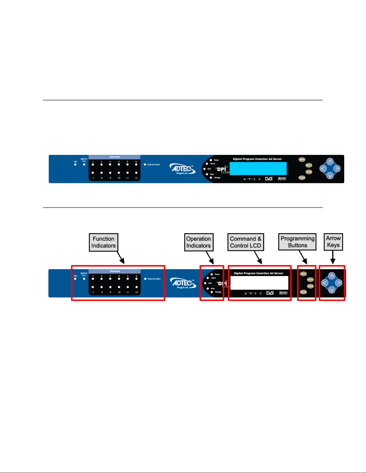
Front Panel
The Function Buttons and Directional Keypad of the DPI-1200 are used to configure and
monitor the channel configurations and output of the device.
Panel Diagram
Front Panel LEDs
As illustrated in the diagram above, LED indicators are grouped on the DPI1200 front panel
in two sections. The Function indicators describe the media insertion actions being
performed on the unit's outputs. The Operation indicators describe the physical operations
of the DPI1200 unit.
Channel Function Indicator LEDs (Channels 1-12)
● Green
○ Solid: connected and ready to insert
○ Flashing: inserting/commercial playout
● Yellow
○ Solid: connecting/trying to connect
○ Flashing: trigger received, at pre-roll mode
● Red
○ Solid: disconnected
Page 13

○ Flashing: attempting to connect / Insertion Failing
● Off: (not lit)
○ Channel is Disabled or turned off
System / Operation Status Indicator LEDs
● Power
○ Green: Power is on
○ Off (not lit): Power is off
● Alarm
○ Off (not lit): no alarm
○ Yellow: minor alarm
○ Red: major alarm
● Link
○ Green: link detected
○ Off (not lit): no link detected
● Busy
○ Green: system / traffic activity
○ Off (not lit): no activity from unit
● Storage
○ Green: media in storage
○ Off (not lit): no media in storage
Disabled Product State: When the product is in a disabled state, the LCD will relay the
following information; “Product Error.” This state is generally only used when a factory
restore is performed. If that is the case, note that all of the configurations have been
returned to factory defaults including Network configurations. To reapply network
configurations simply press the Down arrow when in this state to navigate through the
network menu. In the event that you see a similar message followed by a phone number,
this indicates that the Temporary keys on the device have expired and you should contact
your sales representative.
Programming Function Buttons and Arrow Keys
Page 14

The DPI-1200 Ad Server has an LCD display on the front panel. Using the Mode, Select,
Enter, Escape buttons and directional buttons, you can navigate the front panel menu and
control the unit
Control Function
Mode Cycles through the available menus
Select selects a menu or sub-menu
Enter enter a value placed into a menu field
Escape return one level within a menu or to the main menu
Directional Keypad
● Arrow keys control the cursor on the LCD display and are used to page through the
options in a menu/sub-menu and to place entries in fields.
Unit Security
Rules:
Page 15

● The DPI-1200 is always logged in on startup.
● If the device has logged out due to accident, or a login duration timer being set (see
below), you will need to log back in. To log in from a logged-out status follow the key
sequence below. Note that the key sequence spells the word U-S-E-R.
Step Action
1 Press <Select>
2 Press <Up> arrow
3 Press <Select>
4 Press <Enter>
5 Press <Right> arrow
6 Press <Enter>
The front panel also has a login duration capability. This setting allows you to specify a time
frame in which the unit will automatically log itself out if it receives no control inputs via the
front panel or API session.
Possible Values:
0 (Zero): The unit will not auto-log-out
1-9: The number of minutes until log out if no input is received.
Main System Banner Menu
The main banner menu is a non-editable display. It displays the current installed and applied
firmware version the unit is running as well as the product name.
Key Functions
While in the main menu, the following navigation keys have special meaning in the operation of
the DPI-1200.
Increase LCD Contrast / Brightness
1. Press and hold <Mode> and <Escape> buttons
2. Press <Up> arrow to desired level
Decrease LCD Contrast / Brightness
1. Press and hold <Mode> and <Escape> buttons
2. Press <Down> arrow desired level
Reset the unit
1. Press and hold <Mode> and <Escape> buttons
2. Press the <Right> arrow
3. Release all three buttons at the same time
System Menu
Page 16

The following diagram illustrates the structure and flow of the System Menu on the Adtec
DPI-1200 device:
Login
Item Function Options API Command
Login If the front panel is in a ‘logged out’
state, all configurations are read only.
User must login to change values.
Login
Duration
Specifies the time-out value for
automatically logging out of the front
panel once a user logs in for security
purposes. Setting a time of 0 disables
automatic logout capabilities
N/A N/A
0 - 9 ( minutes ) *.SYSD LDR
Network Sub-menu
Item Function Options API
Command
Ethernet IP
Address
Ethernet
Mask
IP address of unit on your network user-defined using
<left/right arrow>
and <select>
buttons
default is
192.168.10.48
Defines the unit relative to the rest of
your network
user-defined using
<left/right arrow>
and <select>
buttons
default is
255.255.255.0
*.SYSD IPA
*.SYSD IPM
Ethernet
DHCP
GigE IP
Address
GigE Mask defines unit relative to the rest of an user-defined using *.SYSD IPM
Dynamic Host Configuration Protocol;
allows the device to self-locate network
Ethernet parameters
route of traffic in/out on IPTV user-defined using
On (finds own DHCP
Address)
Off (defaults to last
entered IP Address)
default is OFF
<left/right arrow>
and <select>
buttons
default is
192.168.20.48
*.SYSD
DHCP
*.SYSD IPA
eth1
Page 17

IPTV network <left/right arrow>
and <select>
buttons
default is
255.255.255.0
eth1
Gateway IP
Address
traffic director for off-LAN resources user-defined using
<left/right arrow>
and <select>
buttons
default is
192.168.10.1
*.SYSD GIP
Time Sub-menu
Item Function Options Adtec API
Command
Time specifies system time
24 Hour Clock Format
Timezone specifies time zone unit
operates in
user-defined using <left/right
arrow> and <select> buttons
user-defined using <left/right
arrow> and <select> buttons
*.SYSD TIM
*.SYSD TIZ
NTP Sub-menu
Item Function Options Adtec API
Commands
NTP Status Network Transfer
Protocol
NTP IP
Address
IP address for Network
Transfer Protocol
server
Displays whether or not your unit is
in sync with the designated NTP
server
user-defined using <left/right
arrow> and <select> buttons;
default = 0.0.0.0
*.SYSD NIP
STATUS
*.SYSD NIP
Alarm Sub-menu
Item Function Options
Event Record Log of events outside of operating
parameters
scroll up and down to view log
items
Page 18

Mirror Sub-menu
Item Function Options Commands
Host Mode Set the automated ftp
mirroring mode.
Host IP
Address
Client Name
& Password
IP address for Mirroring
Server
Sets the Username and
Password to access
Mirroring Server
Client (Turns Mirroring Off)
Mirror List (Use a
MIRRORLISTFILE to add/delete
local files)
Mirror Client (Mirrors all files
found on Server)
CCMS (Used with TBGS and
other enterprise systems)
user-defined using <left/right
arrow> and <select>
buttons;
default = 0.0.0.0
user-defined using <left/right
arrow> and <select> buttons
Username and password are
separated by a comma
Raid Status
Item Function Options
*.SYSD HOM
*.SYSD HIP
*.SYSD CPW
Raid Status Provides status of the internal 750 GB
mirrored RAID 1 Array (read only)
Array OK: RAID 1 and Drives are
functioning well
Degraded: Loss of 1 of the
mirrored RAID drives
Host Name
Item Function Options Adtec API
Commands
Name DIsplays and allows editing
of the host name
user-defined using
<left/right arrow>
and <select>
buttons
*.SYSD name
Firmware Version
Item Function Options Adtec API
Commands
Firmware Displays current version of firmware (read N/A *.DPID VRN
Page 19

only)
NetSet Menu
The following diagram illustrates the structure and flow of the NetSet Menu on the Adtec
DPI-1200 device.
Control Function Options API
Command
Mode Defines whether a current net set
is active and able to be used or
inactive
Days On Specifies the specific days of the
week to use the configured
NetSet
Type Defines the type of cue to trigger
insertion for that channel
Start
Condition
Defines the event sequence to
start the insertion process (DTMF
or GPI Only)
InsertNet (Typical
Setting) Activates NetSet
for use
Inactive Setting is to to
be used for trigger
ALL (Typical Argument)
NetSet is used for all day
of the week
DTMF_TONE Audible
tone generated by
receiver
GPI Momentary Contact
Closure
SCHED_TIME Scheduled
timed insertion based on
schedule and clock
SCTE35 Network
Embedded Cue passed
from splicer to the DPI
DTMF Cue: 123*
GPI: Closed or Open
If using SCTE35, leave
blank
*.DPID NST #
x MODE
*.DPID NST #
x DAYSON
*.DPID NST #
x TYPE
*.DPID NST #
x STARTCOND
Stop
Condition
Pre-Roll Defines the time, in milliseconds,
Post-Roll Defines the time, in milliseconds,
Defines the event sequence to
stop the insertion process (DTMF
or GPI Only)
to delay the start of an ad
insertion once a valid cue trigger
is received (DTMF or GPI Only)
to delay the end of an ad
insertion back to network
DTMF Cue: 123#
GPI: Closed or Open
If using SCTE35, leave
blank
0 - 9000 *.DPID NST #
0 - 7000 *.DPID NST #
*.DPID NST #
x STOPCOND
x PREROLL
x PSTROLL
Page 20

programming once a valid Stop
Condition is received. (DTMF or
GPI only)
Avial Time The total maximum time
available for a series of spots
played during a commercial
insertion
End By Condition which must be met
before the Splicer will switch
back to the network feed
Note: Up to twelve Insertion Channels are available on the product. If using API
Commands, the ‘#’ denoted in the NST Commands above are relevant to the twelve channel
destinations indexed 0 - 11. The ‘x’ denoted in the Commands above represents the NetSet
Index value indexed 0 - 9. (Each channel has 10 possible netset configurations.)
Hours:Minutes:Seconds
CCMS Mode 00:00:00
Spot:(typical setting)
Switch back when the
spots have finished
running and a scheduled
break is completed
SpotAvail: Switch back
when the spot is finished
and the configured Avail
time is met
*.DPID NST #
x AVAIL
*.DPID NST #
x ENDBY
Splicer Menu
The following diagram illustrates the structure and flow of the Splicer Menu on the Adtec
DPI-1200 device.
Item Function Options Adtec API
Command
Channel
Mode
Channel
Name
Splicer IP
Address
Splicer
Name
Enable or disable
Splicer
communication
Output channel name
on the Splicer for
channel
Management IP
Address of the
Splicer used for
channel
Name of the Splicer
Interface used for
OFF: Turned off / disabled
ASI: ASI Streaming Channel
IP: IP Streaming Channel
text field;
Note: Must match the name of
channel on Splicer
user-defined; numeric field in
format: xxx.xxx.xxx.xxx
text field;
Note: Match the name of the
*.DPID CHM #
*.DPID CLN #
*.DPID SIA #
*.DPID SPN #
Page 21

channel Splicer Interface / Site
Splicer
Chassis #
Splicer
Card #
Splicer Port #Physical connection,
Splice Lead InNumber of
CCMS ID # The Unique numeric
Number distinction of
the Splicer Chassis
for channel
The numeric
representation of the
physical card, on the
connected Splicer,
where the Splicer
Port connection is
made
on the configured
Splicer Card, for the
insertion stream
milliseconds before
each splice point to
start the insert
Traffic and Billing
Native Mode
Identifier for
scheduling and
verification
text field; 1-999 available
Consult Splicer documentation
Note: Can usually be left at 1
text field; 1-10 available
(Consult Splicer documentation)
Some splicer cards may be labled
A, B, C, D or E. So, A = 1, B = 2,
etc...
text field; 1-20 available
(Consult Splicer documentation)
text field; Valid Range is 300 1500 ms.
user-defined; numeric field in
format: xxxxx
Referred to as the CCHHH Number
*.DPID SCS #
*.DPID SCA #
*.DPID SPO #
*.DPID SLI #
*.DPID CNV C #
CCMS
Format
Break
Repeat
Splice
Multicast
Address
Traffic and Billing
media/Spot ID
Format in schedule,
also referred to as
parsing format
Configures the
behavior for dealing
with incomplete
breaks
The IP Address of
which the insertion
stream is served to
the splicer via the
GigE Port.
Valid Multicast
addressing range is
224.10.XXX.XXX to
239.XXX.XXX.XXX.
A Unicast address will
be the unique IP of
20/20 uses 6 right-justified
characters
NOVAR uses 8 right-justified
characters
RAW uses all 11 characters
LEFT uses left-justified characters
NONZERO Omits any leading zeros
ON partially played break can be
triggered again, resuming with the
previously aborted spot
OFF (Typical Setting)
user-defined; numeric field in
format: xxx.xxx.xxx.xxx
*.DPID CNV P #
*.DPID BRP #
*.DPID MSI #
Page 22

the Ad insertion
receiving interface on
the Splicer
Splice
Multicast
Port
Note: Up to twelve Insertion Channels are available on the product. If using API
Commands, the ‘#’ denoted in the Commands above are relevant to the twelve channel
destinations indexed 0 - 11.
Port number used for
IP Streaming in
conjunction with
Multicast Address.
user-defined; numeric field
Note: If you are using the same
Multicast or Unicast address for
multiple channels, the Multicast
Port will need to be incremented by
2 for each channel
(The valid range is 1-65535)
*.DPID MSP #
Cue Menu
The following diagram illustrates the structure and flow of the Cue Menu on the Adtec DPI1200 device.
Item Function Options Adtec API
Commands
DTMF
History
DTMF Time
Newest
DTMF Time
Oldest
GPI State Displays the current
Displays the recent
history of tones for
each channel being
cued with DTMF cues
Displays the time the
most recent DTMF
tone sequence was
heard for a channel
Displays the time the
oldest DTMF tone
sequence was heard
for a channel
state of the GPI
Trigger port for a
Non-editable display, status only. *.DPID THS #
Non-editable display, status only.
Displayed in the format: Weekday
Hour:Minutes:Seconds:Milliseconds
(Day HH:MM:SS.mmm)
Non-editable display, status only.
Displayed in the format: Weekday
Hour:Minutes:Seconds:Milliseconds
(Day HH:MM:SS.mmm)
Non-editable display, status only *.DPID GHS #
*.DPID THS #
TIMENEW
*.DPID THS #
TIMEOLD
Page 23

channel
GPI Time
Changed
GPO State Sets condition of port
DTMF
Speaker
Note: Up to twelve Insertion Channels are available on the product. If using API
Commands, the ‘#’ denoted in the commands above are relevant to the twelve channel
destinations indexed 0 - 11.
Displays the time the
most recent GPI
trigger received for a
channel
state for trigger
reception
Routes a given input
tone source to the
speaker on the
DTMF board
Non-editable display, status only.
Displayed in the format: Weekday
Hour:Minutes:Seconds:Milliseconds
(Day HH:MM:SS.mmm)
OPEN Port is normally open
CLOSED Port is normally closed
(Front Panel Only Configuration)
ON Turns on speaker for DTMF
Tone for channel
OFF Turns off the speaker for the
channel
*.DPID GHS #
TIMENEW
*.DPID GPO #
*.DPID SRP #
Back Panel Diagram
The back panel contains the ports and connection points for the device.
Connections
Connection Function
AC Power AC Power- standard 3-pin plug (70-240 VAC 50-60 Hz), 5Vdc Power
(x2) - External Power Only
GigE GigeE Interface - MPTS Output over UDP / Management
Firewire FireWire Reserved for future use
Terminal Monitor API Serial Communication Interface / Serial Port used for
Troubleshooting
Fast Ethernet 10/100 base T-Ethernet interface
RS232 DB9; Used to communicate with redundancy switch (ASI Model Only)
Page 24

USB 2.0 (hardware present, but not currently supported by firmware)
I/O DTMF or GPIO
Inputs 1-12
ASI Redundancy
Input (Optional)
No-C-NC Redundancy Tally, used to hook up to an external alarm device
ASI Outputs (3) BNC 75 ohm, Triple Mirrored ASI Outputs
DTMF tone / GPIO board option for DPI-1200
Used to link 2 DPI-1200’s in tandem; one as primary, one as backup
Chapter 3 - Using the Web Application
Introduction
Adtec Digital has deployed a web-based configuration and control software application for
our products. The program is optimized to work with the following browser versions:
● Firefox: 3.5 (recommended) and higher
● MS Internet Explorer: 8.0 and higher
● Safari: 3.0 and higher
● Google Chrome: 5.0 and higher
Note for Safari users:
● The program is designed to use the Bonjour Zero Configuration Protocol.
○ When using Safari, click on the " ^^ " symbol to open a networked devices
list.
○ Select the device to point the browser to that device's IPA.
Logging In
Access the application by pointing your web browser to the unit's IP address. The following
screen (image reduced for clarity) will appear:
Page 25

Log in to the application by clicking the "Proceed to Login" button and typing in the user name
'adtec' and the password 'none' in the pop-up box that appears.
The application has two operating windows, the Status Window and the Main Window:
Status Window: The Status Window is fixed on the left-hand side of the screen- it will display
regardless of what function is being displayed in the Main Window. The current status
parameters of the unit's are always in view and are updated in real time.
Page 26

Main Window: The Main Window is used to access the device's configurations and operating
settings.
Help Notes: Help blurbs are available for the configurations on each tab; click on the "Question
Mark" symbol next to the configuration name for a pop-up screen explaining the control.
Upgrading your device
To upload new firmware versions, click on the <Upload> button in the top navigation bar next to
Log Out. A pop-up screen will allow you to browse for the firmware file by clicking Upload within
the pop-up screen. After the new version is uploaded, its availability on the device will display
under "available versions".
After the new version is uploaded, Click <Install> to extract the firmware. It will then be
available under Installed Versions.
Once you have the version you wish to use in the Installed Versions list, you can select into it
by clicking the select button. The unit will reboot and come up running in the new version.
Chapter 4 - How-To Guides
How to Complete a Manual Upgrade
You can upgrade your Adtec device's firmware via built-in web-based application, described
in the Upgrade Tab section, or via a Telnet/FTP session, described in this article.
To update your Adtec device 's firmware via a Telnet session, perform the following:
Manual Upgrade Process
Step Action
1 Obtain the desired firmware version file from Adtec Support website via
www.adtecdigital.com
note*: Firmware releases are found in the Support -> Documentation & Downloads
-> DPI 1200 Ad Server -> section of the website, there will be a link to the
released firmware version for download.
note**: Windows Internet Explorer renames adtec firmware file extensions to .gz .
When saving please add a t within the extension to read .tgz if IE has renamed
your file.
2 Using your favorite FTP client to upload the firmware file to the device.
If you are unfamiliar with FTP you may use a 'My Computer' window and type in
the address bar, ftp://adtec:none@192.168.10.48 where 192.168.10.48 should be
replaced with the IP Address of YOUR device. You may then drag and drop the
Page 27

firmware file into the hd0 folder.
3 Open a Telnet session and enter the IP address of the unit you are going to update.
note*: If you are unfamiliar with telnet, open a command prompt window
(windows: start -> run.., mac: macintosh hd -> applications -> utilities ->
terminal) and type: telnet 192.168.10.48
4 Enter the username as ' adtec ' and the password as ' none '.
5 *.sysd vrn search - from the results, look for the pathname of recently uploaded
firmware file
6 *.sysd vrn install [pathname of the .tgz file]
ex: *.sysd version install /media/hd0/DPI-v1.04.05.nfcms.tgz
How to Connect via Telnet
* Using Telnet (standard 23 port)* To connect to your device using a terminal session, you
will need to set the IP address of the unit. See earlier instructions on setting the IP via the
front panel.
Using a terminal window, complete the following:
Step Action
1 Type 'telnet x.x.x.x' in a terminal window, without quotes, where x.x.x.x is the IP
address of the unit.
2 Press <Enter>.
3 When prompted for a username, enter adtec.
4 When prompted for a password, enter none.
Once you see "User 'adtec' connected", the session is open and you may issue API
commands to the unit.
Page 28

For the DPI-1200 device, there are specific commands for the DPI Channels and the unit's
operating system. Each has a unique way of accepting commands. If using telnet is your
preferred method of communication to your device, familiarize yourself with the API
commands and their respective command handlers. For more information on this, point your
browser to the IPA of your unit and look through the API notes that are described for the
device.
How to Connect via FTP
FTP connections can be made to the adtec device using any ftp client.
Host: <ipa of the unit>
Default Username: adtec
Default Password: none
Port: 21
FTP is only useful for collecting logs from the device.
Media Encoding Guidelines
All media used for insertion should conform to SCTE guidelines for DPI insertion. The
encoded material should be in a transport stream format at a constant bit rate. All audio
should be encoded to match that of the insert stream.
How to Use API Commands
Page 29

The Adtec DPI-1200 device is unique in that it handles up-to twelve different streaming
channels for Ad Splicing. To accommodate commands for controlling each channel, you will
need to specify which channel you are working with for each command you issue.
Please make the following adjustments:
● Instead of using *.dpid as noted the API descriptions, you will need to use.
○ *.dpid CLN 0 to specify the first channel.
○ *.dpid CLN 1 to specify the second channel.
○ *.dpid CLN 2 to specify the third channel.
Example: (*.dpid CLN 3) will give you the channel name of the third channel.
Most of the operational features of the Adtec DPI-1200 Ad Server can be controlled via
telnet using Adtec's API commands. A reference of the API commands applicable to the
DPI-1200 can be found on our website or on the Help Tab of the Web UI and select the API
Notes Link.
Setting Time Zone and Daylight Savings
This allows the user to properly configure or view the Timezone offset and Daylight Savings
time changes for the DPI-1200 Ad Server in an API telnet command window. Instructions on
connecting to the DPI with telnet can be found in the How-To Guides. The API Command
TIMEZONE has three different argument options [std] offset [daylight savings rule] where
the std and
Daylight savings rule are optional. The form of the command TIMEZONE and argument
explanation is as follows:
Command Handler: SYSD
Command: TIMEZONE | TIZ | TZ
Arguments:
std Name of the Time Zone
offset Hours offset from UTC (coordinated universal time)
dst Daylight Savings Setting
To configure only the time zone offset, you will use the following example:
*.SYSD TIZ -5 This sets the units’ offset to -5 from UTC
To configure the units’ time zone offset with a label for the offset, you will use the following
example:
*.SYSD TIZ EST-5 This sets the units’ offset to -5 from UTC and labels the setting as
Eastern Standard Time
Format to add Daylight Savings Time:
Page 30

Std offset dst [offset],start[/time],end[time]
The initial std and offset specify the standard time zone, as described above, the remainder
of the specification describes when Daylight Saving Time is in effect. The start field is when
Daylight Saving Time goes into effect and the end field is when the change is made back to
standard time. The format of the start / end fields are formatted as: Mm.w.d. This specifies
day (d) of week (w) of month (m). The day d must be between 0 (Sunday) and 6. The week
w must be between 1 and 5; week 1 is the first week in which day d occurs, and week 5
specifies the last d day in the month. The month m should be between 1 and 12.
The time fields specify when, in the local time currently in effect, the change to the other
time occurs.
An example, here is how you would specify the Eastern time zone in the United States,
including the appropriate Daylight Saving Time and its dates of applicability. The normal
offset from UTC is -5 hours; since this is west of the prime meridian, the sign is negative.
Summer time begins on the first Sunday in April at 2:00am, and ends on the last Sunday in
October at 2:00am:
*.SYSD EST-5EDT,M4.1.0/2,M10.5.0/2
In 2007, the times for changing Daylight savings time in the US changed to:
EST-5EDT,M3.2.0/2,M11.1.0/2
Chapter 5 - System Integration Application Notes
This section contains various how to guides that will assist you in the configuration and
integration of your unit to operate as part of your over all distribution system. These
procedures are based on firmware version 1.04.03. When the DPI-1200 is powered up, the
front panel will display “System Banner – DPI 1200 V1.04.03”.
There has been every effort to ensure the accuracy of the information provided in these
guides. However, due to software, firmware and hardware changes, there may be some
degree of difference between what is represented here and what is displayed on your
equipment.
Splicer Setup and Configuration
Page 31

The DPI-1200 Ad Server works in conjunction with a various network splicers for seamless
commercial insertion. Those include, but are not limited to: Motorola CherryPicker (DM3200
or DM6400), RGB’s BNPxr, BNP2xr, BNP3xr, Cisco DCM and Scopus IVG 7500. (Adtec Digital
does not endorse particular product) This section provides a guide on the general setup and
configuration of some of these splicers
Motorola DM6400 Network CherryPicker
™
Screen and guide samples are taken from DM 6400 Version: netcp5.0.1 (Build 18)
Licensing
When using the DPI-1200 in conjunction with a Motorola CherryPicker, you will need a
license for each channel desired for insertion. Appropriate licenses will need to be purchased
from your Terayon sales representative or reseller.
To check the DM to make sure it has the needed ad insertion license keys, you will need to
log into the web interface and select Accounts from the top menu bar.
This page will have a section with the heading Product Licenses. If you do not see a line
item called Ad Insertion, MPEG-2 Ad Insertion or MPEG-4 AVC Ad Insertion or the
existing license has already expired, you will need to contact Motorola or your distributor for
licensing service. Because each license key is linked to a specific Data Flash, you will need
to look up the serial number for the Data Flash in your DM CherryPicker. (Illustration below)
Time Sync
Per SCTE30 protocol, Time synchronization is required due to the passing of time between
the Server and the Splicer. The delay on a TCP/IP message is somewhat unpredictable and
is affected by other machines on the network. By having the machines synchronized, time
can be passed between the two machines without concern for normal network delays
keeping the splicing very accurate. The time synchronization system must be able to keep
the Splicer and Server within +/- 15 ms of each other.
One possible method is to use Network Time Protocol (NTP) to keep the Server and the
Splicer in synchronization. A network common host system NTP server could be used since
this will also typically exist in a cable headend that has a network infrastructure. The DPI-
Page 32

1200 can be used as an NTP server if an NTP network is not available. Please refer to the
NTP Menu options under the System Menu description in Chapter 3 and additional time
configurations later in this chapter.
To configure the DM CherryPicker to time sync from the DPI-1200, select Configure from
the DM Network CherryPicker Desktop menu bar.
Select the Controller from the configuration tree. The controller information displays on the right
side of the screen along with the NTP Configuration options. (illustrated figure below)
Note: NTP sync may take up to 30 minutes to be effective
Configuring the splicer for ad grooming
Note: Terayon does not support ad insertion on loopback input modules. (source DM
Network CherryPicker 4.0 User Guide 2004)
Physical Connections
ASI - Connection of the DPI-1200 Ad Server will need to occur on one of the four inputs of
a DVB-ASI Input Module on the back of the CherryPicker using a coaxial cable with BNC
connectors. See illustration below:
Back Labeling diagram of port / slot configuration:
Page 33

The coax cable, from the DPI, will connect to a port (1-4 illustrated below). If the
connection is recognized, the corresponding LED with the same number will light up Green.
4 port DVB-ASI Input Module
IP - Connection of the DPI-1200 will need to be on the same IP Ingest Network as any
other IP Input Stream going to the DM6400. A standard GigE Ethernet Cable will be used.
Note: Please note all physical connections and their labels. This information is needed to
configure the DPI properly to work with the attached splicer.
Grooming your ads into the channel
Once you have properly configured your splicer with all of the channels you are wanting to
output and the DPI has been configured with the proper IP and channel information
matching that of the splicer, the corresponding output program will have [Ad Server
Connected] attached to the output name. (illustration below)
CherryPicker and Motorola are registered trademarks of their respective companies
RGB Broadcast Network Processor (BNP)
™
Screen and guide samples are taken from RGB BNPxr Version: 1.2.5 Build# 18453
Licensing
Page 34

When using the DPI-1200 in conjunction with a RGB BNP, you may need grooming with DPI
license key(s) depending on your application. Appropriate licenses will need to be purchased
from your RGB sales representative or reseller.
To check the BNP to make sure it has the needed license keys, you will need to log into the
BNP Element Manager web interface and select Maintenance > License from the top
menu. (illustrated window below)
Time Sync
Per SCTE30 protocol, Time synchronization is required due to the passing of time between
the Server and the Splicer. The delay on a TCP/IP message is somewhat unpredictable and
is affected by other machines on the network. By having the machines synchronized, time
can be passed between the two machines without concern for normal network delays
keeping the splicing very accurate. The time synchronization system must be able to keep
the Splicer and Server within +/- 15 ms of each other.
One possible method is to use Network Time Protocol (NTP) to keep the Server and the
Splicer in synchronization. A network common host system NTP server could be used since
this will also typically exist in a cable headend that has a network infrastructure. The DPI1200 can be used as an NTP server if an NTP network is not available. Please refer to the
NTP Menu options under the System Menu description in Chapter 3 and additional time
configurations later in this chapter.
To configure the RGB BNP to time sync from the DPI-1200, select the Configuration Tab
from the BNP Element Manager window, and select the Global subtab. (Illustrated below)
Set the NTP Address 1 to that of the NTP Server or the connected DPI-1200 Ad Server.
Note: You must have the NTP Server or DPI up and running prior to booting the BNP.
Page 35

Configuring the splicer for ad grooming
Physical Connections
ASI - Connection of the DPI-1200 Ad Server will need to occur on one of the six ports
available using a coaxial cable with BNC connectors. The number of ASI ports in your BNP
chassis depends on the number of ASI cards that are installed. Up to three ASI cards can be
installed, each with six ports. See illustrated example below:
The coax cable will connect to one of the available ASI port connections on an available
card. If the connection is good, the corresponding LED with the same number will light up
Green next to the port with the corresponding port number.
IP - Connection of the DPI-1200 will need to be on the same IP Ingest Network as any
other IP Input Stream going to the RGB BNP or attached directly to the IP Input Card
(Typically Labeled E) using an SFP Optical Module Adapter. A standard GigE Ethernet Cable
will be used. If the connection is good, the corresponding LED with the same number will
light up Green next to the port with the corresponding port number.
Note: Please note all physical connections and their labels. This information is needed to
configure the DPI properly to work with the attached splicer.
Page 36

Note: The attached ASI and/or Ethernet port will need to be configured for proper data flow
direction. This is set from the Element Manager by selecting the Configuration Tab then
ASI or GigE Ports subtab. (Following illustration)
Grooming your ads into the channel
Once you have properly configured your splicer with all of the channels you are wanting to
output and the DPI has been configured with the proper IP and channel information
matching that of the splicer, the image icon associated with your program contained in your
output transport stream will change. The new icon will have an arrow pointing toward the
program name. (illustration below)
RGB Networks is a registered trademark of RGB Networks Inc.
Page 37

Chapter 6 - Scheduling
Scheduling the DPI
"Schedule” in the CCMS format (.sch) is required disregarding the types of triggering
methods such as analog DTMF cueTone, GPI/GPO, Sched. Time, manual and digital cueTone
– SCTE35 (detected by the Splicer). Similar to the analog Ad Insertion system, Duet – DPI1200 provides NO play-spot command. The action to achieve a function similar to 'play-spot'
is to trigger an event manually. The content being played is according to the preprogrammed CCMS schedule.
Schedules, verifications, commercial media files, etc… are stored in separate directories in
the operating system.
Helpful system directory paths
Directory Pathway Notes
Media Directory /media/hd0/media/ Location for all media to be inserted
Schedule Directory /media/hd0/schins/ Location for all schedule files to be used
Verification Directory /media/hd0/verins/ Location for all verification files
Log Directory /media/hd0/log/ Location for all system log files
CCMS Schedule Reference
A schedule file exists for each channel of insertion. The file name will always be eight
characters in length plus the three character extension of SCH.
MDDCCHHH.SCH
M –
Represents month of intended airing
Range 1 - C Ex. 1 = January, C = December
Hexadecimal format
DD –
Represents day of month of intended airing
Range 01-31 Ex. 05
CC –
Numeric identifier or Channel ID
Range 01-99
HHH –
Page 38

Numeric identifier or Headend ID
Range 001- 099
The records within the SCH file follow the following format. Each record is terminated by a
carriage return and line feed. Each record will all be at least 77 bytes in length. The fields
of each record are determined by its byte position. Each field is separated by a space
character. All times are formatted in military time.
Field # Field Name Bytes Description
1 Event Type 1-3 Type of event defined by record
(LOI, REM,END, NUL)
2 Scheduled Date 5-8 T&Bs approximation of the date
when the event will occur
(formatted - MMDD)
3 Scheduled Time 10-5 T&Bs approximation of the time of
day when the event will occur
(formatted HHMMSS)
4 Window Start Time 17-20 Time of day to begin window of
opportunity for event to occur
(formatted - HHMM)
5 Window Duration Time 22-25 Length of window of opportunity for
event to occur (formatted - HHMM)
6 Break Number Within Window 27-29 Break sequence number within
window of opportunity for event to
occur
7 Position Number Within Break 31-33 Position sequence number for event
within break
8 Scheduled Length 35-40 Scheduled event length
(formatted - HHMMSS)
9 Actual Aired Time 42-47 Actual aired time of day used in
VER file. (Formatted HHMMSS)
10 Actual Aired Length 49-56 Actual aired length used in VER file
(formatted - HHMMSSCC)
11 Actual Aired Position Within
Break
12 Spot Identification 62-72 T&Bs spot identification code used
58-60 Actual sequential position number
that event occurred in. Used in VER
file
by adManage as the commercial file
name. See Headend>File Name
Length configuration on how this
spot ID is converted into a file
name.
Page 39

13 Status Code 74-77 Completion status Code used
in VER file.(Definition of Status
Codes later in this chapter)
14 Advertiser Name 79-110 Advertiser’s name as identified in
T&B System
15 Advertiser Spot Name 112-131 Advertiser’s Spot Name as
identified in T&B
16 Scheduled / Fill 133-136 Identifies the spot as either being
scheduled contractually or used as
filler in order to complete a
commercial break.
17 Traffic System Reserved 138-143 Reserved for use by the Traffic
System
18 User Defined 145-NNN For use in tracking other data.
adManage uses this field in Merged
schedules to identify the event line
as a local or interconnect event.
Manual CCMS Schedule Creation
The simplest way of creating a CCMS schedule is by using Notepad. Name format of
schedule file is MDDCCHHH.SCH.
● M - Represents month of intended airing.
○ Range 1-C.
○ Example: 1 = January and C = December.
○ Hexadecimal.
● DD - Represents day of month of intended airing.
○ Range 01-31.
○ Example: 25.
● CC - Numeric identifier or Channel ID.
○ Range 01-99.
● HHH - Numeric identifier or Headend ID.
○ Range 001-999.
CCHHH is the same as Schedule ID under "ChXX Schedule ID" of "SPLICER MENU". To save
the file, make sure that “All Files” type is selected under “Save as type”: (illustration
indicates a schedule for channel 2 headend 088 for September 25th)
Page 40

Example CCMS Schedules
Schedule Interpretation
Most remarks are referencing the first line of the schedule
Datum Field Notes
REM 1 Remark – text after REM will not be executed by DPI-1200 as
scheduled
LOI 1 Language of Interaction. Each line of LOI refers to one event for
DPI-1200
0925 2 September 25th - the date of the event which has to match the
first three characters of the schedule file name. One schedule file
is for one day only
081500 3 8:15 am -when the first event is estimated to occur; again, an
estimate only – it does not mean that the event will absolutely
occur at 8:15 am precisely. This necessitates the next two
settings.
0800 4 8:00 am - is the earliest possible time when the 8:15 am event
will be occurred. It is to prepare the DPI-1200 (to open up a time
Page 41

window) for receiving any possible trigger to start this line of
event. Triggers will be discussed later in this chapter.
0100 5 1 hour – it is how long the time window will be opened. For this
event, the time window will be opened from 8:00 am till 9:00 am.
It means when the DPI receives a specific trigger between 8:00
am till 9:00 am, then, the commercial clip “Spot #1” will be played
001 6 1 - The break number within the window
001 7 1 – The position sequence of the scheduled insert within the break
000030 8 30 seconds, it is the scheduled length for this event - usually the
same as the duration of the commercial clip selected. It means
“Spot #1” is a 30-second commercial clip
000000
00000000
000
000TEST0001 12 The file name of the Spot #1 commercial clip. By default (CNVP is
0000 13 Status code such as 0001 means aired successfully will be
Adtec Test Cl… 14 The Advertiser Client Description. (optional) Used for informational
Spot #1 15 The Spot Title of the commercial to be played. (optional) Used for
Sch 16 Identifies the spot as either being contractually scheduled or used
9
10
11
925002088.VER will be generated automatically with the updates
of actual aired time, length and position to these three fields.
These three fields always show zeroes in .SCH file
set to NOVAR), last 8 characters are used: alpha numeric field.
The first three characters are reserved and always show zeroes.
Any file names shorter than 8 characters have to be filled up with
zero(es) prefix to fill this field by 11 characters. If CNVP is set to
RAW, then all 11 characters in alpha-numeric format will be used
but then, the mpeg files should not contain any extension
generated automatically to the 92502088.VER file. More status
code information can be found in Appendix E of the adManage
Manual. This field always shows zeroes in a .SCH file
purposes only
informational purposes only
as filler in order to complete a commercial break. (optional)
00030 17 A duplication of the scheduled length of the spot. (optional) Used
for informational purposes only
CCMS Scheduling using adManage
Please refer to adManage TM Manual. It can be downloaded from the Support Section of our
web page at: www.adtedigital.com
● Configure each channel's scheduling identifier, load schedules and media.
○ At this point, you will need to use the "API" interface to perform configuration.
Page 42

■ Using telnet to the "API" port 23, connect and log in.
■ To test the connection, type "*<Enter>" and you should see a "0"
returned.
The channel-headend scheduling identifier is used to map this channel to one in your traffic
system. It should be in the form CCHHH, where CC is the channel identifier from 00-99 and
HHH is the headend identifier from 000-999.
● Type the command " *.dpid cnv c <index> <CCHHH> " where index is the (zero-
based) channel index (0-11).
○ The default configuration for channel 1 is "01001".
● To change this to channel 36 for headend 3, the command would be *.dpid cnv c 0
36003
○ The response should be "OK".
● Enter the command again without the CCHHH value to query the setting, so " *.dpid
cnv c 0 " should reply "OK".
○ Native Mode ID: 0 36003
After configuring the scheduling identifier, the scheduler will automatically load the schedule
from the schedule directory (/media/hd0/schins) when it is available. The name of the
schedule should be in the format MDDCCHHH.SCH, where m is a single letter representing
the month (1-9, A, B, C), dd is the day of the month (00-31), and CCHHH is the scheduling
identifier.
Spots referenced by the schedule should exist in the directory /media/hd0/media . The
scheduler has a configuration that controls the way the "spot ID" field in the schedule is
interpreted. The field in the schedule is 11 characters wide, but the default setting ("novar")
interprets the spot ID field by using only the 8 right-most characters of the spot ID field.
CCMS Verification Status Codes
Status Code Definition Possible Cause
0001 Aired Successfully
0002 Generic Failed to Air The scheduled event was not run by the DPI. All
events are marked with a 0002 at the beginning of
the broadcast day. As the event is run by the DPI,
the status code is changed to an actual error code
0010 Failed, Device Not
Ready
0012 Failed, Unknown
Error
Possible hardware or splicing connection / timing
issue
If any stall conditions occur during playback, the
spot will not be verified, even if the system was able
to continue after the stall condition. The actual
played length will be updated in the VER file for
Page 43

partial verifications.
0013 Failed, Timeout The break was closed before spot could be aired.
Problem with media to be inserted. Timing issues
with stream to be spliced
0020 Failed, No Ad Copy in
Inserter
0023 Failed, No Cue in
Window
The DPI did not have the scheduled ad copy to play.
Causes include: - Material not copied into adManage
MasterVideoLibrary2.
- The material is not in the inserter because of a
communication error.
- The material is on the headend PURGE list (see
Content Management Purge).
No cue was received in the scheduled window. See
the chapter on Cue Methods for more information
Triggering Explained
DTMF Tone Triggers
DTMF tone board is an option for DPI-1200.
The Integrated Satellite Receiver Decoder (IRD) typically has a DTMF port which provides
audio cue tones. Alternately, some networks use the secondary audio (SAP) channel to
provide the cue tones. The DTMF tones should be nominally spaced by 50msec and be
between 0.5v and 1.0v peek to peak.
Appearance of DTMF connector on the DPI-1200 back panel:
● Connect + and – for DTMF analog tone input to DPI-1200.
● 12 DTMF connectors, each corresponding to its channel number – for example, DTMF
01 connector is for channel 01.
● To configure Netset, please refer to NETSET MENU.
GPI / GPO Triggers
Page 44

GPI/GPO trigger comes with the DTMF board option. GPI uses the I/O port on the DTMF
connector, and the Ground cable uses the G port (see diagram above).
Connect I/O and G to form a circuit.
● There are a total of 12 GPI (General Purpose Input) connectors, each corresponding
to its channel number, for instance, GPI 01 is the connector is for channel 01.
○ To configure GPI port, refer to the CUE MENU section.
● There is one General Purpose Output (GPO) connector.
○ To configure GPO port, refer to the CUE MENU section.
SCTE35 Triggers
A trigger embedded into the original network signal passed directly to the Splicer. It is
detected and triggered by the Splicer to the DPI.
Please refer to your specific splicer model's manual (non-Adtec material) for more
information
Manual Trigger
The manual trigger is the basic, fundamental trigger for the DPI-1200.
● Open a telnet session to the DPI-1200.
● At the prompt, type: *.DPID TG 0 6000 0
○ Triggers channel 01 at a pre-roll time of 6000 milliseconds (6 seconds)
following the Avail Time in the CCMS Schedule.
Chapter 7 - Appendix
Appendix A - GNU General Public License
Version 2, June 1991 Copyright (C) 1989, 1991 Free Software Foundation, Inc.
59 Temple Place, Suite 330, Boston, MA 02111-1307 USA
Everyone is permitted to copy and distribute verbatim copies of this license document, but
changing it is not allowed.
Preamble
The licenses for most software are designed to take away your freedom to share and change
it. By contrast, the GNU General Public License is intended to guarantee your freedom to
share and change free software--to make sure the software is free for all its users. This
General Public License applies to most of the Free Software Foundation's software and to
any other program whose authors commit to using it. (Some other Free Software
Foundation software is covered by the GNU Library General Public License instead.) You can
apply it to your programs, too.
When we speak of free software, we are referring to freedom, not price. Our General Public
Licenses are designed to make sure that you have the freedom to distribute copies of free
software (and charge for this service if you wish), that you receive source code or can get it
Page 45

if you want it, that you can change the software or use pieces of it in new free programs;
and that you know you can do these things.
To protect your rights, we need to make restrictions that forbid anyone to deny you these
rights or to ask you to surrender the rights. These restrictions translate to certain
responsibilities for you if you distribute copies of the software, or if you modify it.
For example, if you distribute copies of such a program, whether gratis or for a fee, you
must give the recipients all the rights that you have. You must make sure that they, too,
receive or can get the source code. And you must show them these terms so they know
their rights.
We protect your rights with two steps: (1) copyright the software, and (2) offer you this
license which gives you legal permission to copy, distribute and/or modify the software.
Also, for each author's protection and ours, we want to make certain that everyone
understands that there is no warranty for this free software. If the software is modified by
someone else and passed on, we want its recipients to know that what they have is not the
original, so that any problems introduced by others will not reflect on the original authors'
reputations.
Finally, any free program is threatened constantly by software patents. We wish to avoid the
danger that redistributors of a free program will individually obtain patent licenses, in effect
making the program proprietary. To prevent this, we have made it clear that any patent
must be licensed for everyone's free use or not licensed at all.
The precise terms and conditions for copying, distribution and modification follow.
GNU GENERAL PUBLIC LICENSE TERMS AND CONDITIONS FOR COPYING, DISTRIBUTION
AND MODIFICATION
0. This License applies to any program or other work which contains a notice placed by the
copyright holder saying it may be distributed under the terms of this General Public License.
The "Program", below, refers to any such program or work, and a "work based on the
Program" means either the Program or any derivative work under copyright law: that is to
say, a work containing the Program or a portion of it, either verbatim or with modifications
and/or translated into another language. (Hereinafter, translation is included without
limitation in the term "modification".) Each licensee is addressed as "you". Activities other
than copying, distribution and modification are not covered by this License; they are outside
its scope. The act of running the Program is not restricted, and the output from the Program
is covered only if its contents constitute a work based on the Program (independent of
having been made by running the Program). Whether that is true depends on what the
Program does.
1. You may copy and distribute verbatim copies of the Program's source code as you receive
it, in any medium, provided that you conspicuously and appropriately publish on each copy
an appropriate copyright notice and disclaimer of warranty; keep intact all the notices that
refer to this License and to the absence of any warranty; and give any other recipients of
the Program a copy of this License along with the Program. You may charge a fee for the
physical act of transferring a copy, and you may at your option offer warranty protection in
exchange for a fee.
2. You may modify your copy or copies of the Program or any portion of it, thus forming a
work based on the Program, and copy and distribute such modifications or work under the
terms of Section 1 above, provided that you also meet all of these conditions:
Page 46

a) You must cause the modified files to carry prominent notices stating that you changed
the files and the date of any change.
b) You must cause any work that you distribute or publish, that in whole or in part contains
or is derived from the Program or any part thereof, to be licensed as a whole at no charge
to all third parties under the terms of this License.
c) If the modified program normally reads commands interactively when run, you must
cause it, when started running for such interactive use in the most ordinary way, to print or
display an announcement including an appropriate copyright notice and a notice that there
is no warranty (or else, saying that you provide a warranty) and that users may redistribute
the program under these conditions, and telling the user how to view a copy of this License.
(Exception: if the Program itself is interactive but does not normally print such an
announcement, your work based on the Program is not required to print an announcement.)
These requirements apply to the modified work as a whole. If identifiable sections of that
work are not derived from the Program, and can be reasonably considered independent and
separate works in themselves, then this License, and its terms, do not apply to those
sections when you distribute them as separate works. But when you distribute the same
sections as part of a whole which is a work based on the Program, the distribution of the
whole must be on the terms of this License, whose permissions for other licensees extend to
the entire whole, and thus to each and every part regardless of who wrote it.
Thus, it is not the intent of this section to claim rights or contest your rights to work written
entirely by you; rather, the intent is to exercise the right to control the distribution of
derivative or collective works based on the Program. In addition, mere aggregation of
another work not based on the Program with the Program (or with a work based on the
Program) on a volume of a storage or distribution medium does not bring the other work
under the scope of this License.
3. You may copy and distribute the Program (or a work based on it, under Section 2) in
object code or executable form under the terms of Sections 1 and 2 above provided that
you also do one of the following:
a) Accompany it with the complete corresponding machine-readable source code, which
must be distributed under the terms of Sections 1 and 2 above on a medium customarily
used for software interchange; or,
b) Accompany it with a written offer, valid for at least three years, to give any third party,
for a charge no more than your cost of physically performing source distribution, a complete
machine-readable copy of the corresponding source code, to be distributed under the terms
of Sections 1 and 2 above on a medium customarily used for software interchange; or,
c) Accompany it with the information you received as to the offer to distribute
corresponding source code. (This alternative is allowed only for noncommercial distribution
and only if you received the program in object code or executable form with such an offer,
in accord with Subsection b above.)
The source code for a work means the preferred form of the work for making modifications
to it. For an executable work, complete source code means all the source code for all
modules it contains, plus any associated interface definition files, plus the scripts used to
control compilation and installation of the executable. However, as a special exception, the
source code distributed need not include anything that is normally distributed (in either
source or binary form) with the major components (compiler, kernel, and so on) of the
Page 47

operating system on which the executable runs, unless that component itself accompanies
the executable.
If distribution of executable or object code is made by offering access to copy from a
designated place, then offering equivalent access to copy the source code from the same
place counts as distribution of the source code, even though third parties are not compelled
to copy the source along with the object code.
4. You may not copy, modify, sublicense, or distribute the Program except as expressly
provided under this License. Any attempt otherwise to copy, modify, sublicense or distribute
the Program is void, and will automatically terminate your rights under this License.
However, parties who have received copies, or rights, from you under this License will not
have their licenses terminated so long as such parties remain in full compliance.
5. You are not required to accept this License, since you have not signed it. However,
nothing else grants you permission to modify or distribute the Program or its derivative
works. These actions are prohibited by law if you do not accept this License. Therefore, by
modifying or distributing the Program (or any work based on the Program), you indicate
your acceptance of this License to do so, and all its terms and conditions for copying,
distributing or modifying the Program or works based on it.
6. Each time you redistribute the Program (or any work based on the Program), the
recipient automatically receives a license from the original licensor to copy, distribute or
modify the Program subject to these terms and conditions. You may not impose any further
restrictions on the recipients' exercise of the rights granted herein. You are not responsible
for enforcing compliance by third parties to this License.
7. If, as a consequence of a court judgment or allegation of patent infringement or for any
other reason (not limited to patent issues), conditions are imposed on you (whether by
court order, agreement or otherwise) that contradict the conditions of this License, they do
not excuse you from the conditions of this License. If you cannot distribute so as to satisfy
simultaneously your obligations under this License and any other pertinent obligations, then
as a consequence you may not distribute the Program at all. For example, if a patent license
would not permit royalty-free redistribution of the Program by all those who receive copies
directly or indirectly through you, then the only way you could satisfy both it and this
License would be to refrain entirely from distribution of the Program. If any portion of this
section is held invalid or unenforceable under any particular circumstance, the balance of
the section is intended to apply and the section as a whole is intended to apply in other
circumstances. It is not the purpose of this section to induce you to infringe any patents or
other property right claims or to contest validity of any such claims; this section has the
sole purpose of protecting the integrity of the free software distribution system, which is
implemented by public license practices. Many people have made generous contributions to
the wide range of software distributed through that system in reliance on consistent
application of that system; it is up to the author/donor to decide if he or she is willing to
distribute software through any other system and a licensee cannot impose that choice. This
section is intended to make thoroughly clear what is believed to be a consequence of the
rest of this License.
8. If the distribution and/or use of the Program is restricted in certain countries either by
patents or by copyrighted interfaces, the original copyright holder who places the Program
under this License may add an explicit geographical distribution limitation excluding those
Page 48

countries, so that distribution is permitted only in or among countries not thus excluded. In
such case, this License incorporates the limitation as if written in the body of this License.
9. The Free Software Foundation may publish revised and/or new versions of the General
Public License from time to time. Such new versions will be similar in spirit to the present
version, but may differ in detail to address new problems or concerns. Each version is given
a distinguishing version number. If the Program specifies a version number of this License
which applies to it and "any later version", you have the option of following the terms and
conditions either of that version or of any later version published by the Free Software
Foundation. If the Program does not specify a version number of this License, you may
choose any version ever published by the Free Software Foundation.
10. If you wish to incorporate parts of the Program into other free programs whose
distribution conditions are different, write to the author to ask for permission. For software
which is copyrighted by the Free Software Foundation, write to the Free Software
Foundation; we sometimes make exceptions for this. Our decision will be guided by the two
goals of preserving the free status of all derivatives of our free software and of promoting
the sharing and reuse of software generally.
NO WARRANTY
11. BECAUSE THE PROGRAM IS LICENSED FREE OF CHARGE, THERE IS NO WARRANTY FOR
THE PROGRAM, TO THE EXTENT PERMITTED BY APPLICABLE LAW. EXCEPT WHEN
OTHERWISE STATED IN WRITING THE COPYRIGHT HOLDERS AND/OR OTHER PARTIES
PROVIDE THE PROGRAM "AS IS" WITHOUT WARRANTY OF ANY KIND, EITHER EXPRESSED
OR IMPLIED, INCLUDING, BUT NOT LIMITED TO, THE IMPLIED WARRANTIES OF
MERCHANTABILITY AND FITNESS FOR A PARTICULAR PURPOSE. THE ENTIRE RISK AS TO
THE QUALITY AND PERFORMANCE OF THE PROGRAM IS WITH YOU. SHOULD THE PROGRAM
PROVE DEFECTIVE, YOU ASSUME THE COST OF ALL NECESSARY SERVICING, REPAIR OR
CORRECTION.
12. IN NO EVENT UNLESS REQUIRED BY APPLICABLE LAW OR AGREED TO IN WRITING
WILL ANY COPYRIGHT HOLDER, OR ANY OTHER PARTY WHO MAY MODIFY AND/OR
REDISTRIBUTE THE PROGRAM AS PERMITTED ABOVE, BE LIABLE TO YOU FOR DAMAGES,
INCLUDING ANY GENERAL, SPECIAL, INCIDENTAL OR CONSEQUENTIAL DAMAGES ARISING
OUT OF THE USE OR INABILITY TO USE THE PROGRAM (INCLUDING BUT NOT LIMITED TO
LOSS OF DATA OR DATA BEING RENDERED INACCURATE OR LOSSES SUSTAINED BY YOU
OR THIRD PARTIES OR A FAILURE OF THE PROGRAM TO OPERATE WITH ANY OTHER
PROGRAMS), EVEN IF SUCH HOLDER OR OTHER PARTY HAS BEEN ADVISED OF THE
POSSIBILITY OF SUCH DAMAGES.
END OF TERMS AND CONDITIONS
How to Apply These Terms to Your New Programs
If you develop a new program, and you want it to be of the greatest possible use to the
public, the best way to achieve this is to make it free software which everyone can
redistribute and change under these terms.
To do so, attach the following notices to the program. It is safest to attach them to the start
of each source file to most effectively convey the exclusion of warranty; and each file should
have at least the "copyright" line and a pointer to where the full notice is found.
<one line to give the program's name and a brief idea of what it does.> Copyright (C)
<year> <name of author>
Page 49

This program is free software; you can redistribute it and/or modify it under the terms of
the GNU General Public License as published by the Free Software Foundation; either
version 2 of the License, or (at your option) any later version.
This program is distributed in the hope that it will be useful, but WITHOUT ANY WARRANTY;
without even the implied warranty of MERCHANTABILITY or FITNESS FOR A PARTICULAR
PURPOSE. See the GNU General Public License for more details.
You should have received a copy of the GNU General Public License along with this program;
if not, write to the Free Software Foundation, Inc., 59 Temple Place, Suite 330, Boston, MA
02111-1307 USA
Also add information on how to contact you by electronic and paper mail.
If the program is interactive, make it output a short notice like this when it starts in an
interactive mode:
Gnomovision version 69, Copyright (C) year name of author Gnomovision comes with
ABSOLUTELY NO WARRANTY; for details type `show w'. This is free software, and you are
welcome to redistribute it under certain conditions; type `show c' for details.
The hypothetical commands `show w' and `show c' should show the appropriate parts of
the General Public License. Of course, the commands you use may be called something
other than `show w' and `show c'; they could even be mouse-clicks or menu items-whatever suits your program.
You should also get your employer (if you work as a programmer) or your school, if any, to
sign a "copyright disclaimer" for the program, if necessary. Here is a sample; alter the
names:
Yoyodyne, Inc., hereby disclaims all copyright interest in the program `Gnomovision' (which
makes passes at compilers) written by James Hacker. <signature of Ty Coon>, 1 April 1989
Ty Coon, President of Vice
This General Public License does not permit incorporating your program into proprietary
programs. If your program is a subroutine library, you may consider it more useful to permit
linking proprietary applications with the library. If this is what you want to do, use the GNU
Library General Public License instead of this License.
Appendix B - Troubleshooting Guide
Problem Solution
New IP addresses don't work Check: are your eth0 and eth1 addresses on the
same subnet? If so change one of them to a
different subnet
I cannot get Ethernet (LAN)
connectivity to my DPI-1200
1. Verify that the LINK LED (center group, front
panel) is lit.
a. If the LED is not illuminated, verify the
connection between the Ethernet patch cord
and the hub/switch.
b. An Ethernet cross-over cable will not workit must be a patch cord.
2. Ensure that the port on the hub/switch is not the
Page 50

MDI or chaining port- if this port was used, move the
patch cord to a non- MDI or -chaining port.
Channel indicators are neither red
or green
Channel indicators flash red and
yellow
Channel indicator flashes red during
insert and then goes back to green
Verification files show a status of
0013 “Time Out”
Verification files show a status of
0023 “No Cue”
NTP Clock will not sync to address Check the NTP server to make sure that it is a Linux
The channel has been administratively disabled or
feature locked. Re-enable the port via the front panel
or command API, if unlocked
The DPI has lost communication with the splicer for
that channel. Check the splicer configuration for that
channel and the splicer interface for issues with the
output.
There is a discrepancy between the splicer and the
DPI. Check the time sync and media being used.
Check the timing sync between the DPI and the
splicer. Check the media to be inserted for proper
encoding and audio formats to the stream
Check cue method being used. If DTMF or GPI, check
the connector cable running between the receiver
and DPI. If SCTE35, check the insertion stream and
splicer configuration to make sure that it is available
and used
stratum server and the time server daemon is
running.
Appendix C - Understanding the DPI System Log File
System Operators
CHNLMGR – Channel Manager
CMDL – Command Log
FTPC – File Transfer Protocol Client
MIRROR – Mirror Client
SCHED – Schedule Daemon
STRM – Stream Manager
TRGRD – Trigger Daemon
Page 51

CHNLMGR: The channel Manager interacts with the splicer. The dpi has 12
channels that are referenced by 0 – 11. When a cue is received from a network
(the TRGRD catches the triggers) the channel manager will send a request to the
splicer to insert on the requested channel.
The TRGR Daemon receives a GPI Trigger for channel 3. Notice the State is 1.
Feb 4 00:02:12 dpi-010E09 [TRGRD]: 250003 Netset ACTIVE and Type is GPI, sending GPI
to State Machine for channel: 3 at index: 0
Feb 4 00:02:12 dpi-010E09 [TRGRD]: 250003 GPI Trigger; Chan: 3; Preroll: ; Sec:
12.272129
Feb 4 00:02:12 dpi-010E09 [TRGRD]: 250003 Inserting GPI on Chan: 3 State: 1 Time:
4988ccf4
Feb 4 00:02:12 dpi-010E09 [TRGRD]: 250003 Storing GPI into buffer on Chan: 3 State: 1
Time: 4988ccf4
The CHNLMGR for channel 3 starts processing the trigger for a splice at the proper
time and cues the scheduler
Feb 4 00:02:12 dpi-010E09 CHNLMGR-03: 90013 Processing trigger for splice at
1233702138,772129, avail 0 stop insert 0
Feb 4 00:02:12 dpi-010E09 CHNLMGR-03: 250003 Cueing scheduler0
The SCHED receives the information from the CHNLMGR and builds the playlist
Feb 4 00:02:12 dpi-010E09 SCHED: 250003 03, Cue received:1233702132 545737
Feb 4 00:02:12 dpi-010E09 SCHED: 250003 03, Build
playlist: /media/hd0/media//312CMCH0027.MPG 1233702132 547513
Feb 4 00:02:12 dpi-010E09 SCHED: 250003 03, Build
playlist: /media/hd0/media//312CCAI0182.MPG 1233702132 552598
Feb 4 00:02:12 dpi-010E09 SCHED: 250003 03, Build
playlist: /media/hd0/media//312CLIN0024.MPG 1233702132 554922
Feb 4 00:02:12 dpi-010E09 SCHED: 250003 03, Build
playlist: /media/hd0/media//312GNGF0003.MPG 1233702132 557551
Feb 4 00:02:12 dpi-010E09 SCHED: 250003 03, Build
playlist: /media/hd0/media//312CMCH0028.MPG 1233702132 560231
The CHNLMGR for channel 3 starts processing two spots for the insertion and
sends the request to the splicer
The splicer replies with the go ahead: SCTE30 splice response (100). The channel
manager will send this same request for each spot and if the splicer says ok then it
will return the same response.
Feb 4 00:02:12 dpi-010E09 CHNLMGR-03: 250003 Processing scheduled
spot: /media/hd0/media//312CMCH0027.MPG (5032, 4)
Feb 4 00:02:12 dpi-010E09 CHNLMGR-03: 250003 buf(6), 1233702138 272129
1040 /media/hd0/media/312CMCH0027.MPG
Page 52

Feb 4 00:02:12 dpi-010E09 CHNLMGR-03: 250003 Sending splice request, last offset =
-4161 5032
Feb 4 00:02:12 dpi-010E09 CHNLMGR-03: 250003 Processing scheduled
spot: /media/hd0/media//312CLIN0024.MPG (5034,
Feb 4 00:02:12 dpi-010E09 CHNLMGR-03: 90007 SCTE30 splice response (100)
Each channel has two streams assigned to it. In this case channel 3 has streams 6
and 7 managed by the stream manager (STRM). As one spot is being played the
next spot is cueing behind it. After the spot is played by the first stream it will cue
another spot while the second stream is being played. You can see that
demonstrated here:
The processes swap until all 5 of the files are played.
Feb 4 00:02:18 dpi-010E09 STRM-06:
250003 /media/hd0/media/312CMCH0027.MPGStarted at 1233702138, 272182 micro
Feb 4 00:02:27 dpi-010E09 STRM-06:
250003 /media/hd0/media/312CMCH0027.MPGFinished
Feb 4 00:02:28 dpi-010E09 STRM-07:
250003 /media/hd0/media//312CCAI0182.MPGStarted at 1233702148, 142137 micro
Feb 4 00:02:57 dpi-010E09 STRM-07:
250003 /media/hd0/media//312CCAI0182.MPGFinished
Feb 4 00:02:58 dpi-010E09 STRM-06:
250003 /media/hd0/media/312CLIN0024.MPGStarted at 1233702178, 62900 micro
Feb 4 00:03:17 dpi-010E09 STRM-06:
250003 /media/hd0/media/312CLIN0024.MPGFinished
Feb 4 00:03:17 dpi-010E09 STRM-07:
250003 /media/hd0/media/312GNGF0003.MPGStarted at 1233702197, 941731 micro
Feb 4 00:03:42 dpi-010E09 STRM-07:
250003 /media/hd0/media/312GNGF0003.MPGFinished
Feb 4 00:03:42 dpi-010E09 STRM-06:
250003 /media/hd0/media/312CMCH0028.MPGStarted at 1233702222, 862673 micro
Feb 4 00:03:47 dpi-010E09 STRM-06:
250003 /media/hd0/media/312CMCH0028.MPGFinished
After each insertion the FTPC will push the VER file to the server (HIP). It will
upload the VER file after the SCHED has made its updates on the appropriate spot
and VER file. Notice that the FTPC process triggers after the SCHED process makes
and update following the insertion.
Feb 4 00:03:45 dpi-010E09 SCHED: 90017 updateSpotStatus (3): schTime:1233732600,
m_unDayStartSec:1233702000, index:3 pSpotStatus->Result:100 resultCodeMap:0001
Feb 4 00:02:15 dpi-010E09 [FTPC]: Uploaded: /media/hd0/verins/20405901.VER to
62.45.52.86:21/Verifications/20405901.VER
Page 53

Once the splice is complete there is a message from the CHANLMGR. If the end
time is subtracted from the start time it will give you the avail time or total
insertion time.
Feb 4 00:03:49 dpi-010E09 CHNLMGR-03: 90009 100,005036, -4161,
(out) /media/hd0/media/312CMCH0028.MPG
Feb 4 00:03:49 dpi-010E09 CHNLMGR-03: 250003
Feb 4 00:03:49 dpi-010E09 CHNLMGR-03: 250003 <<<SPLICE>>>
Feb 4 00:03:49 dpi-010E09 CHNLMGR-03: 250003 avail: 0
Feb 4 00:03:49 dpi-010E09 CHNLMGR-03: 250003 start: 1233702138.772129
Feb 4 00:03:49 dpi-010E09 CHNLMGR-03: 250003 avail end: 1233702138.772129
Feb 4 00:03:49 dpi-010E09 CHNLMGR-03: 250003 end: 1233702228.102129
Feb 4 00:03:49 dpi-010E09 CHNLMGR-03: 250003
Feb 4 00:03:49 dpi-010E09 CHNLMGR-03: 250003 ID: 5032, priorId: 4294967295, state:
COMPLETE, exp start: 1233702138.772129
Feb 4 00:03:49 dpi-010E09 CHNLMGR-03: 250003 exp pad: 000000.000000
Feb 4 00:03:49 dpi-010E09 CHNLMGR-03: 250003 in msg: 5032,0,0,0
Feb 4 00:03:49 dpi-010E09 CHNLMGR-03: 250003 out msg:
5032,1,2976464,892800(887400)
Feb 4 00:03:49 dpi-010E09 CHNLMGR-03: 250003
Feb 4 00:03:49 dpi-010E09 CHNLMGR-03: 250003 ID: 5033, priorId: 5032, state:
COMPLETE, exp start: 1233702148.632129
Feb 4 00:03:49 dpi-010E09 CHNLMGR-03: 250003 exp pad: 000000.000000
Feb 4 00:03:49 dpi-010E09 CHNLMGR-03: 250003 in msg: 5033,0,0,0
Feb 4 00:03:49 dpi-010E09 CHNLMGR-03: 250003 out msg:
5033,1,3120397,2689200(2688300)
Feb 4 00:03:49 dpi-010E09 CHNLMGR-03: 250003
Feb 4 00:03:49 dpi-010E09 CHNLMGR-03: 250003 ID: 5034, priorId: 5033, state:
COMPLETE, exp start: 1233702178.562129
Feb 4 00:03:49 dpi-010E09 CHNLMGR-03: 250003 exp pad: 000000.000000
Feb 4 00:03:49 dpi-010E09 CHNLMGR-03: 250003 in msg: 5034,0,0,0
Feb 4 00:03:49 dpi-010E09 CHNLMGR-03: 250003 out msg:
5034,1,2856844,1792800(1788300)
Feb 4 00:03:49 dpi-010E09 CHNLMGR-03: 250003
Feb 4 00:03:49 dpi-010E09 CHNLMGR-03: 250003 ID: 5035, priorId: 5034, state:
COMPLETE, exp start: 1233702198.442129
Feb 4 00:03:49 dpi-010E09 CHNLMGR-03: 250003 exp pad: 000000.000000
Feb 4 00:03:49 dpi-010E09 CHNLMGR-03: 250003 in msg: 5035,0,0,0
Feb 4 00:03:49 dpi-010E09 CHNLMGR-03: 250003 out msg:
5035,1,2611994,2246400(2238300)
Feb 4 00:03:49 dpi-010E09 CHNLMGR-03: 250003
Feb 4 00:03:49 dpi-010E09 CHNLMGR-03: 250003 ID: 5036, priorId: 5035, state:
COMPLETE, exp start: 1233702223.362129
Feb 4 00:03:49 dpi-010E09 CHNLMGR-03: 250003 exp pad: 000000.000000
Feb 4 00:03:49 dpi-010E09 CHNLMGR-03: 250003 in msg: 5036,0,0,0
Page 54

Feb 4 00:03:49 dpi-010E09 CHNLMGR-03: 250003 out msg:
5036,1,2788872,439200(437400)
Feb 4 00:03:49 dpi-010E09 CHNLMGR-03: 250003
Feb 4 00:03:49 dpi-010E09 CHNLMGR-03: 250003 <<<SPLICE>>>
Feb 4 00:03:49 dpi-010E09 CHNLMGR-03: 250003
The MIRROR process works at separate times. Here you can see the mirroring
process delete old schedules and check the server (62.45.52.86) for new schedule
files.
Feb 4 00:00:27 dpi-010E09 [MIRROR]: Checked 0 files, 0 failed.
Feb 4 00:00:57 dpi-010E09 [MIRROR]: Started CCMS process with 62.45.52.86.
Feb 4 00:00:59 dpi-010E09 [MIRROR]: Deleted: /media/hd0/schins//20302901.SCH
Feb 4 00:01:16 dpi-010E09 [MIRROR]: Deleted: /media/hd0/schins//20303901.SCH
Feb 4 00:01:38 dpi-010E09 [MIRROR]: Deleted: /media/hd0/schins//20305901.SCH
Feb 4 00:01:55 dpi-010E09 [MIRROR]: Deleted: /media/hd0/schins//20307901.SCH
Feb 4 00:02:11 dpi-010E09 [MIRROR]: Deleted: /media/hd0/schins//20321901.SCH
The FTPC will upload all verification files to the (HIP) just after midnight as a safeguard
against corrupt files or any error that may have occurred.
Feb 4 00:00:06 dpi-010E09 [FTPC]: Uploaded: /media/hd0/verins/20323901.VER to
62.45.52.86:21/Verifications/20323901.VER
Feb 4 00:00:06 dpi-010E09 [FTPC]: Uploaded: /media/hd0/verins/20325901.VER to
62.45.52.86:21/Verifications/20325901.VER
The internal schedule (SCHED) it will make periodic polls sure the trigger daemon
is up and running.
Feb 4 00:55:00 dpi-010E09 SCHED: 253083 Triggering trigger daemon. Trigger register: 20
Trigger time: 1233705300,117309
Additional Logging Notes and examples
In this case, the DPI cannot communicate with the splicer and responds with the
message disconnecting.
Feb 9 00:02:53 dpi-010CC6 CHNLMGR-02: 250003 Disconnecting
Here the DPI cannot recognize the channel name because the name is not the
same in the splicer and DPI
Feb 6 00:01:42 dpi-010D71 CHNLMGR-08: 90018 Invalid or Unknown Channel Name
List of log codes as of dpi-v1.02.07:
= 90000 BASE_FOR_DPI
Page 55

90001 TRACE_MSG_SCTE30_BASE,
// 90002 TRACE_MSG_SCTE30_APPSTART,
// 90003 TRACE_MSG_SCTE30_PROTOCOL_ESTABLISHED,
// 90004 TRACE_MSG_SCTE30_LOST_CONNECTION,
// 90005 TRACE_MSG_SCTE30_CUEREQ,
// 90006 TRACE_MSG_SCTE30_SPLICEREQ,
// 90007 TRACE_MSG_SCTE30_SPLICERESP,
// 90008 TRACE_MSG_SCTE30_SPLICEIN,
// 90009 TRACE_MSG_SCTE30_SPLICEOUT,
// 90010 TRACE_MSG_SCTE30_GENRESP,
// 90011 TRACE_MSG_CMDCUE,
// 90012 TRACE_MSG_ERRCFGLOAD,
// 90013 TRACE_MSG_TRIGGER,
// 90014 TRACE_MSG_DPID_START,
// 90015 TRACE_MSG_SPLICETIMEOUT,
// 90016 TRACE_MSG_ABORT,
// 90017 TRACE_MSG_UPDATESTATUS,
// 90018 TRACE_MSG_SCTE30_INIT_FAILED,
// 90019 TRACE_MSG_ERROR_NOT_SPTS,
//91000 BASE_FOR_TRGRD = BASE_FOR_DPI + 1000,
//91001 TRACE_MSG_TRGRD_DTMF_ENABLE,
//91002 TRACE_MSG_TRGRD_DTMF_OBJECT_FAIL,
//91003 TRACE_MSG_TRGRD_DTMF_COM2_FAIL,
//91004 TRACE_MSG_TRGRD_NETSET_GET_MODE_INVALID,
//91005 TRACE_MSG_TRGRD_NETSET_SET_MODE_FAIL,
//91006 TRACE_MSG_TRGRD_NETSET_GET_TYPE_INVALID,
//91007 TRACE_MSG_TRGRD_NETSET_SET_TYPE_FAIL,
//91008 TRACE_MSG_TRGRD_NETSET_XML_PARSE_ERROR,
//91009 TRACE_MSG_TRGRD_NETSET_XML_PARSE_SUCCESS,
You may also see code in the range 250000 - 250009.
LOG_GENERAL_BASE = (MILLION/4),
// Process status
LOG_PROCSTAT_BASE = (0 + LOG_GENERAL_BASE),
LOG_PROCSTAT_START
LOG_PROCSTAT_END
LOG_PROCSTAT_INFO
LOG_PROCSTAT_WARN
LOG_PROCSTAT_ERR
LOG_PROCSTAT_CHILD
LOG_PROCSTAT_REGISTRATION
LOG_PROCSTAT_UNREGISTER
LOG_PROCSTAT_SIGNAL
Page 56

Select SCTE30 Splice Response Messages
ResultResult Name Description
100 Successful Response
104 Invalid/Unknown Channel
Name
105 Invalid Physical Connection Possible configuration error
108 Splice Failed – Unknown Failure
110 No Insertion Channel Found This error shall be returned if the Insertion
111 No Primary Channel Found This error shall be returned if the Primary
112 Splice_Request Was Too Late The Splice_Request message was not received
113 No Splice Point Was Found The Splicer was unable to find a valid point to
Possible configuration error
Channel is missing at the start of a splice.
Channel is missing at the Splice-in or Splice-out
times.
early enough (3 seconds) for the Splicer to
initiate the splice.
splice into the Primary
Channel
Appendix D - Technical Specifications
Inputs
10/100 base-T Ethernet Connector: 8 pin RJ45 x1
Gigabit Ethernet Connector: 8 pin RJ45 x1
NAS Compliant Storage Interface
DTMF/GPI
Twelve GPI or GPO
Twelve DTMF Input (-10 to +0 dB)
Outputs
Page 57

ASI (optional)
Connector: 75 Ohm BNC x3
ISO13818-1 MPEG 2 Transport Stream per EN 50083-9:1997 (188 byte only)
PCR, PTS re-stamping
*Overall egress supported bandwidth limit of 160 Mbit/s.
GigE Transport Over IP (TSoIP)
Use: May also be used for control.
Connector: 8 pin RJ45 x1
ISO13818-1 MPEG 2 Transport Stream per EN 50083-9:1997 (188 byte only)
*Overall egress supported bandwidth decreases when using TSoIP streams. The sum of all
UDP streams must fall within the IP supported limit of 100 Mbit/s.
Tally Output (optional ASI Only)
Contact closure for On-Air or external device control
Standards Compliance
Splicing
SCTE 30 Ad Server to Splicer IP based command/control protocol
SCTE 35 Via SCTE 30 from Splicer Transport private data cueing
Video
CableLabs MD-SP-VOD-CEP-I01-040107
Audio
MPEG 1 Layer 2, MPEG 2 Layer 2, ATSC A/52 & A/53 (Dolby Digital AC3) and
AAC Audio Compatible
SPTS - H.264/MPEG-4 Part 10
SPTS - ISO/IEC 13818-1 / MPEG-2
- Supports ANSI/SCTE 20 2003 Captioning
Storage
750GB Mirrored RAID 1
NAS (software included NAS device and hard drives extra)
Host Platform
PowerPC CPU
Linux 2.6 Kernel OS (Hardened)
IPv4 via ETH0 Fast Ethernet
IPv4 via ETH1 GIGE
Serial / Terminal RS232 via RJ45
Serial Port (RJ-48)
GPIO (9 Pin D-sub)
Operating Temperature
0 to 90 Degrees Fahrenheit
Less than 70% RH
Non-Condensing
Active cooling (Push pull Fans)
Page 58

Power Usage
70-240 VAC switching power supply
50/60 Hertz
Rated at 150 Watts nominal usage 40 watts
Physical
Measurements: (H X W X D) 1.75” X 19” X 14”
11 pounds gross weight
Management
8 Button Tactile Raised Keypad Front Panel with Status LEDs
Browser-based Web Interface
10/100 base-T Ethernet and GigE
Terminal Monitor port
HTTP, FTP, Telnet, IP Logging, SNMP MIB II and private MIB, DHCP, (XCP
Adtec encrypted layer 3 protocol)
Use: API Serial Communication Interface
Default Baud Configuration: 38,400 bps 8 data bits 1 stop bit no parity
Connector: 8 pin RJ45 (supplied with DB9 to RJ45 adapter)
Use: Serial Port Used for Troubleshooting (Terminal)
Baud Configuration: 115,200 bps 8 data bits 1 stop bit no parity
Specifications Disclaimer: Specifications subject to change without written notice. Copyright
2013 Adtec Digital. DPI-1200 is a trademark of Adtec Digital. Other product and company
names may be trademarks or registered trademarks of their respective companies. This
information may not, in whole or in part, be copied, photocopied, reproduced and translated, or
reduced to any electronic medium or machine-readable form without prior consent in writing
from Adtec Digital.
 Loading...