

Page 1
DPI-1200
Digital Ad Server
Quick Start Guide
Thank you for your purchase of
the Adtec DPI-1200 Ad Server.
The most recent firmware
releases are available on our support
website, www.adtecdigital.com.
Advanced users can find direct API
command help as part of the on-board
web application, Help Tab.
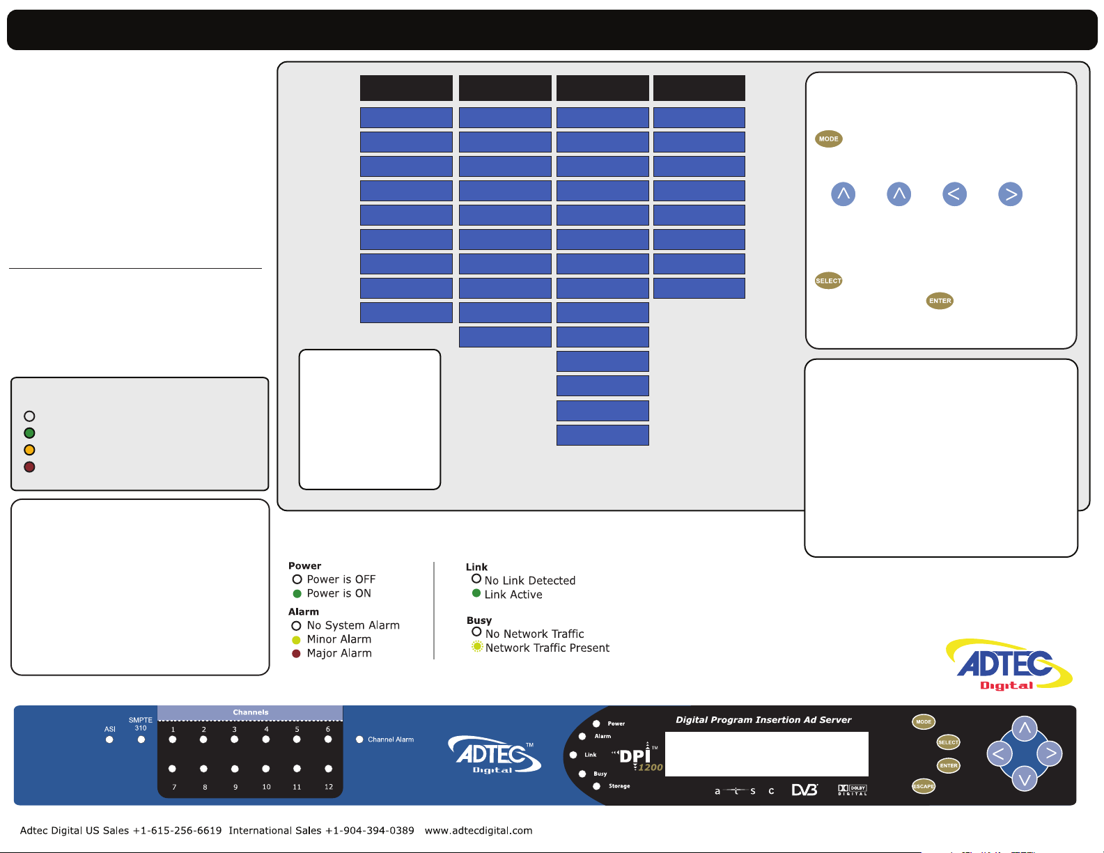
Channels 1 - 12
Not Active
Channel Connected
Pre-Roll / Transitioning
Channel Disconnected
High Availability:
Each channel is individually configurable for
ASI or IP Streaming.
3 x Mirrored ASI ports allows for connection of
up-to 3 separate splicers.
IP streaming via Unicast or Multicast
using the GigE Connection.
*Note: If the same Multicast or Unicast address
for multiple channels, the Multicast Port will need to
be incremented by 2 for each channel.
Example: Channel 1 = Port 2000
Channel 2 = Port 2002
System
Network
RAID Status
Firmware
Reset:
Should you need to
reset your device, you
can do so via the front
panel by pressing the
MODE, ESCAPE and
RIGHT ARROW keys
simultaneously.
System LED Status
Login
Time
NTP
Alarm
Mirror
Name
NetSet
<<CH1 - CH12>>
Mode
Days On
Type
Start
Stop
Pre-Roll
Post-Roll
Avail
End By
Splicer
<<CH1 - CH12>> <<CH1 - CH12>>
Mode
Name
Splicer IPA
Splicer Name
Chassis
Card
Port
Lead In
Schedule ID
Format
Break Repeat
Multicast IPA
Multicast Port
Cue
DTMF History
DTMF Newest
DTMF Oldest
GPI State
GPI Time Changed
GPO State
DTMF Speaker
Front Panel Menus:
Use Mode Button to move
through top layer menus.
Use arrows for navigation
in submenus.
Use select to enter into edit
mode and enter to save
selection.
Units ship with the front panel logged in
by default. If you become logged out and
are prompted for a password, use the
following key sequence for access.
Press <Select> when panel displays
‘User Login -- logged out’
Press <Up arrow>
Press <Select>
Press <Enter>
Press <Right arrow>
Press <Enter>
11.25.2013
Page 2
Getting Connected
To begin, you will need to connect to your device via ethernet directly, or by adding the RD-60
to your local area network.The default address for all Adtec devices is 192.168.10.48.
To connect directly to the device, make sure that your computer and the device have IP
addresses within the same IP class range (ex. 192.168.10.48 for the device and 192.168.10.49 for your
computer). If you need to change the IP address of the device, this can be done via the front panel,
System > Network menu. Using a CAT 5 crossover cable, connect one end to your computer and the
other to the Ethernet port found on the processor section of the back panel. (Some computers can auto
negotiate the connection and a crossover may not be necessary.)
To add the device to a LAN, connect a standard CAT 5 Ethernet cable to your network router
and then to the Ethernet port on the back of the device. If your network is DHCP enabled and you prefer
that over a static IP, you can turn on DHCP for the device via the front panel, System > Network menu.
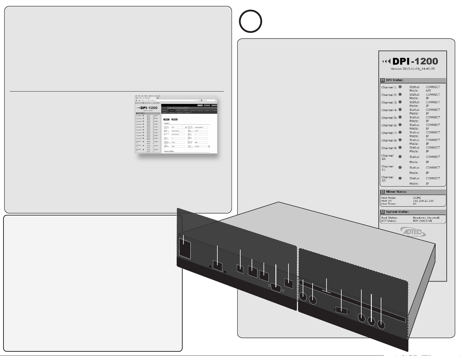
Web-Based Control Application
Adtec Digital has adopted zero-conguration
networking technology, streamlining the setup and
conguration processes for our products. The use of this
technology enables automatic discovery of Adtec devices and
services on an IP network. Used in tandem with the
web-based control and conguration applications we can
now provide 1-click access to any device.
By using the built-in Bonjour© locater in Apple's© Safari©
browser or the plug-ins readily available for IE© or Firefox© browsers, users can locate all of the Adtec devices
on a network by referencing the serial number on the back of the device. Clicking on the unit in the Bonjour©
list will re-route you to a login page. If you do not wish to use Bonjour, you can reach the device’s web
application by pointing your browser to the IP Address of the device. Ex. http://192.168.10.48/. You will be
prompted for a username and password. The default username is ‘adtec’. The default password is ‘none’.
The left-hand panel of the application will report current status in real-time while the right panel
tabs will allow you to congure your device.
Have questions? Each field or group of fields in
our web-based application has a hint button associate
?
with it. It contains information on use of the field or
acceptable ranges.
Getting Started
Once your DPI-1200 is accessible via network, you can set
it up for Splicer connections. You will need to adjust the
configurations using the front panel or web UI. As you make
changes, you will see the status sections on the left hand side of the
web UI adjust. These status sections report the majority of the
critical information needed for monitoring during operation.
Each of these status menus can be collapsed by clicking
on the icon. This allows you to view only that information which is
most critical for you, but keeps a LED indicator visible for all sections
at all times for alarms.
DPI Status:
Includes each channel connection status and method status. One for
each channel.
Mirror Status:
These values indicate the FTP Mirroring Mode used on your unit
along with the host server IP Address.
System Status:
These values provide information on the status and health of the
internal RAID hard drives as well as NTP Time Sync Status with the
configured time server.
Processor ..........................................................................................
Power AC Power - Standard 3 pin plug (70-240 VAC 50 - 60 Hz)
GigE GigE Interface - SPTS/MPTS Output over UDP, FTP, Management
Terminal API Serial Communication Interface / Troubleshooting
Ethernet 10/100 base T Ethernet interface
RS232 DB9/ Used to communicate with redundancy switch
N/A Intended for future use
External Cue Input and ASI Output
ASI Redundant BNC 75 Ohm, Asynchronous Serial Interface
Inputs 1&2
(EN 50083-9)
DTMF/GPIO DTMF Tone Decoder / GPIO Detection
12 Ports
board - 4 pin RST
Redundancy Tally Redundancy Tally, used to hook up to an
external alarm device
Relay Block
ASI Out 1, 2 & 3 BNC 75 Ohm, Asynchronous Serial Interface
(EN 50083-9) Mirrored MPTS Output
...................................
rewoP CA
EgiG
Terminal
tenrehtE
N/A
RS232
1 tuO ISA
2 tuO ISA
3 tuO ISA
External Cue Input & ASI Output
11.25.13
ROSSECORP
ASI Redundant 1
ASI Redundant 2
DTMF / GPIO
Cue Block
Redundancy
Tally Block
N/A
 Loading...