

Page 1

SIMON OW NER'S MANUAL
1
Page 2

FCC Notices
FCC Part 15 Information to the User
Changes or modifications not expressly approved by Interactive Technologies, Inc. can void the user’s authority to operate the equipment.
FCC Part 15 Class B
This equipment has been tested and found to comply with the limits for a Class B digital device, pursuant to part 15 of the FCC Rules. These limits are
designed to provide reasonable protection against interference in a residential installation.
This equipment generates, uses, and can radiate radio frequency energy and, if not installed and used in accordance with the instructions, may cause
harmful interference to radio communications. However, there is no guarantee that interference will not occur in a particular installation.
If this equipment does cause harmful interference to radio or television reception, which can be determined by turning the equipment off and on, the user
is encouraged to try to correct the interference by one or more of the following measures:
• Reorient or relocate the receiving antenna.
• Increase the separation between the equipment and receiver.
• Connect the affected equipment and the panel receiver to separate outlets, on different branch circuits.
• Consult the dealer or an experienced radio/TV technician for help.
FCC Part 68
This equipment complies with part 68 of the FCC Rules. Located on this equipment is a label that contains, among other information, the FCC registration
number and the ringer equivalence number (REN) for this equipment. If requested, this information must be provided to the telephone company.
The REN is used to determine the maximum number of devices that may be connected to your telephone line. In most areas, the sum of all device RENs
should not exceed five (5.0).
If this equipment causes harm to the telephone network, the telephone company may temporarily disconnect your service. If possible, you will be notified
in advance. When advance notice is not practical, you will be notified as soon as possible. You will also be advised of your right to file a complaint with
the FCC.
Your telephone company may make changes in its facilities, equipment, operations, or procedures that could affect the proper operation of your equipment. You will be given advanced notice in order to maintain uninterrupted service.
If you experience trouble with this equipment, please contact the company that installed the equipment for service and repair information. The telephone
company may ask you to disconnect this equipment from the network until the problem has been corrected or you are sure that the equipment is not
malfunctioning.
This equipment may not be used on coin service provided by the telephone company. Connection to party lines is subject to state tariffs.
©1998 INTERACTIVE TECHNOLOGIES, INC.
ITI is a registered trademark of Interactive Technologies, Inc.
SIMON ™ is a trademark of Interactive Technologies, Inc.
Specifications are subject to change. Some features are optional.
For reprints, order manual 466-1575 Rev A Dated October 1998
651-777-2690
651-779-4890
2
Page 3

TABLE OF CONTENTS
Introduction. . . . . . . . . . . . . . . . . . . . . . . . . . . . . . . . . . . 4
Security System Beeps, Lights, and Messages . . . . . 5
How to Use Your Control Panel . . . . . . . . . . . . . . . . . . . 7
How to Use Your Touchpads . . . . . . . . . . . . . . . . . . . . 10
Programming Your System . . . . . . . . . . . . . . . . . . . . . 11
System Tests & Trouble Beeps . . . . . . . . . . . . . . . . . . .14
Your Emergency Evacuation Floor Plan . . . . . . . . . . . .16
Alarm System Limitations . . . . . . . . . . . . . . . . . . . . . . .17
Index . . . . . . . . . . . . . . . . . . . . . . . . . . . . . . . . . . . . . . . . .18
Quick Reference Table . . . . . . . . . . . . . . . . . . . . . . . . . .20
Important Messages to the Owner:
In the following paragraph s there may be some terminolog y that you are not familia r with. Reread this sectio n after you fa miliar ize
yourself with your security system.
Arming Your System with Doors or Windows Open: Any sensors which are open when the system is armed will be bypassed
after the exit delay has expired. This means they will not be protecting your home. If you wish to bypass a sensor after you have
armed your system, you mu st first di sarm the sys tem, then op en the door or window whic h you want byp assed. Your system will
tell you if a protected door or window is open when you arm the system. If your system includes 24-hour protection sensors on
items such as gun or jewelry cases, you must do an additional disarm called subdisarm before accessing the s e a re as to av oi d
causing an alarm. The master access code an d panic code can sub disarm. When the sy stem is disarmed , using the Contr ol Panel, the Remote Handhe ld Touchpad, or Touc htalk 2-Way RF Touchp ad, enter the maste r access code or pa nic code to subdisar m
the system. The Contr o l Pa n el is subdisarmed when th e Disarm button is flash ing. If the panic code was used, an alarm will be
reported to the central station.
CAUTION! If you use the Control Panel to arm your security system when leaving your home, you need to be aware of the following: You need t o exit befo re t he e nd of th e de la y peri od or an a la rm will so und . Re me mber, whe n you arm yo u will hear 2, 3,
or 4 beeps at the beginning of the exit delay (see the table “Panel Beeps” on page 5 of this manual to determine the meaning of
control panel/system beeps). At the end of the exit delay, the system beeps 2, 3, or 4 additional beeps. If you exit at that time
(after the exit delay ), your system assumes yo u are now returning to you r ho me. The system is now countin g do wn the entry
delay time and will expect you to disarm the system within the entry delay time or it will alarm.
Something may have happened while you were away! If you enter your home and controlled lights that are normally off are
on and/or you hear alarm sirens, an intruder may be insid e or another emergency may have occurred. Leave imme di ately, and
call for non-medical emergency help.
Canceling Accide ntal Alarms: Yo u hav e up to 12 0 secon ds (p rogr ammab le by the insta ller) aft er cau sing an accid enta l alarm to
disarm your security system. See your insta ller to determin e this amou nt of time. If th e progr ammed sec onds have passed, y ou
must call the central monitoring station to cancel the alarm.
Notices for UL-Listed Installations:
• This system is suitable for Grade A household burglary applications.
• The Freeze Sensor, Glass Guard and Shock Sensors are not UL Listed.
• The garage door opening feature used with this system has not been evaluated by UL.
3
Page 4
Introduction to Your System
Your security system uses wireless technology to warn your
family about intrusion and fire. It may also be used to control
lights and appliances within your home.
The system is designed to be monitored and/or to send messages to a numeric pager.
The security system uses devices called sensors which use
radio waves to communicat e ala rms to the Control Panel.
The system is supervised, meaning that the Control Panel
checks the status of each sensor to detect problems. If the
Control Panel detec ts tr ou bl e it will n ot ify you wit h b ee ps a nd
indicator lights on the Control Panel itself.
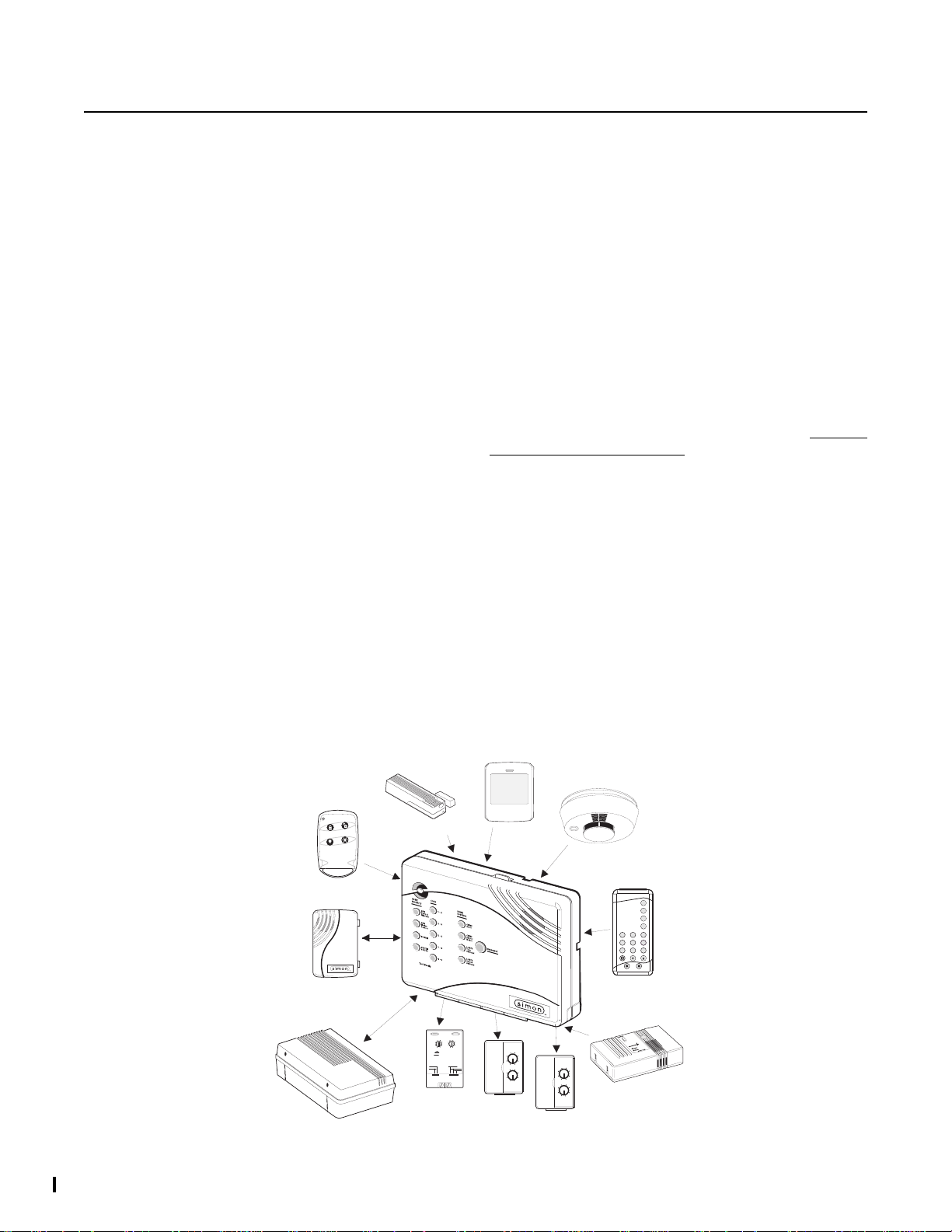
Typical Security System Components
A typical security s ys te m ins tallation consists of the following
devices:
Control Panel
The Control Panel is us ed to o pe ra te an d p ro gra m yo ur s ec urity system. It co mmunicates to you through panel voi ce messages, panel beeps, and by lighting buttons on the Control
Panel. The Control Panel can communicate to a c en tral monitoring stat ion and/or a numeric pager. The Control Pa nel may
come with 2-Way Voice On-Board.” This feature allows the
Central Station to commun icate with the user if there is a problem at the security system site.
Audio Verification Module
The Audio V erificati on Module (AVM) give s the central station
operator the ability to hear what’s happening at the premises
during an alarm and speak directly to the system owner. The
operator can determine how serious an alarm is, find out what
kind of help is needed, and dispatch the appropriate assistance.
Remote Handheld Touchpad and Touchtalk 2Way RF Touchpad
These touchpads are used to control the security system primarily from within the home.
KeyChain Touchpads
KeyChain Touc hpa ds a re us ed to co ntro l the se curi ty syst em
from within or near the outside of your home.
Indoor Motion Sensors
Indoor Motion Sensors detect motion. They may be used for
intrusion protection or to sound chimes on the Control Panel.
Outdoor Motion Sensors
Outdoor Motion Sen sors det ect motion in a pro tected o utdoor
area and can sound chimes or turn on outside lights. They are
not used for intrusion detection.
Door/Window Sensors
Door/Window S ensors detect the opening of a door o r window.
Smoke Sensors
Smoke Sensors detect smoke. They have a built in siren
which sounds when smoke is de tected.
Modules
Modules are used to control lights, app lia nces, and a garage
door. Only unit numbers 1-8 may be used for individual light,
appliance, or garage door control.
MOTION
SENSOR
15
13
11
O
M
LAMP
MODULE
1
3
5
7
9
A
C
E
GK
I
1
3
15
5
13
11
7
9
A
C
O
E
M
GK
I
APPLIANCE
MODULE
SMOKE
SENSOR
SYSTEM
STATUS
ARM
Doors &
Windows
ARM
Motion
Sensors
DISARM
3
1
526
4
89
7
Off
On
EMERGENCY
sP
d&sres Hol hBtoeKy
-
REMOTE
HANDHELD
TOUCHPAD
CARBON
MONOXIDE
DETECTOR
CARBON MONOXIDE
ALARM
8988G21D.DSF
KEYCHAIN
TOUCHPAD
TOUCHTALK
2-WAY RF
TOUCHPAD
AUDIO VERIFICATION
MODULE
DOOR/WINDOW
SENSOR
CONTINUOUS
MOMENTARY
GARAGE DOOR
MODULE
ON
1
3
15
5
13
11
7
9
UNIT CODE
X-10 POWERHOUSE
OFF
A
C
O
E
M
GK
I
HOUSE CODE
SOUNDER ONLY
SOUNDER & RELAY
RELAY ONLY
4
Page 5
Security System Beeps, Lights, and Messages
Your security syst em co mmun ic ates to yo u thr ou gh t he us e of pa nel v oice mess ag es, pane l be eps, in dica tor li gh ts on th e pa nel
itself, and to a numeric pager if programmed.
You communicate to your security system with key presses on the Control Panel, touchpads, or through the use of a remote
telephone. Disarming and pro gr amming require you to input a 4-digit access code. The Master Access Code default is 1-2-3-
4 when the security system is shipped from the factory. You should change it to a code known only by you.
Panel Voice Messages
When you press the buttons on the Control Panel or the touchpads, the Control Panel responds with voice messages. Panel
voice can be enabled or disabled (see “What You Can Change:” on page 11).
These messages ma y res po nd wit h s yste m infor ma tio n o r pro mpt yo u t o tak e fu rt he r act io n. Fo r exa mpl e, if you wan t to di sa rm
the system and you press the DISARM button, the Control Panel responds by saying,
Please enter your access code
.
If you press a button and the feature ha s not been progr ammed into the Contr ol Panel, the pan el voice will respo nd with
not available
intrusion Motion Sensors in your installation. The panel voice would respond with,
. An example of this situa tio n is pressing the Control Panel button CHIME Special Motion when you have no non-
Function not available.
Function
Panel Beeps
Panel beeps are used to indicate keypresses, status, and problems with the system. Panel beeps can be enabled or disabled
(see “What You Can Change:” on page 11).
Use the following table to understand the beeps used by the security system.
Activity Beep Response
ARM Doors & Windows Exit delay beeps sound 2 times when you arm* and 2 times at the end of the delay time;
Entry delay beeps s ound 2 times ever y 5 s econd s and 2 times per s econd durin g the last 10
seconds
ARM Motion Sensors Exit delay beeps sound 3 times when you arm* and 3 times at the end of the delay time;
Entry delay beeps s ound 3 times ever y 5 s econd s and 3 times per s econd durin g the last 10
seconds
ARM Doors/Windows &
Motion Sensors
DISARM 1 beep
Exit delay beeps sound 4 times when you arm* and 4 times at the end of the delay time;
Entry delay beeps s ound 4 times ever y 5 s econd s and 4 times per s econd durin g the last 10
seconds
CHIME DOORS 2 beeps (feature must be programmed by installer)
CHIME SPECIAL MOTION 3 beeps (feature must be programmed by installer)
TEST SENSORS Beeps when sensor tripped
EMERGENCY Beeps and sirens are activated
Trouble Beeps 6 beeps every minute. Press SYSTEM STATUS button twice to stop beeps for 4 hours
* You will not get initial exit de lay beeps if you are ar ming from a Touchtalk 2-Way RF Touchpad.
Note: You may receive a different number of panel beeps if buttons are pressed quickly.
5
Page 6
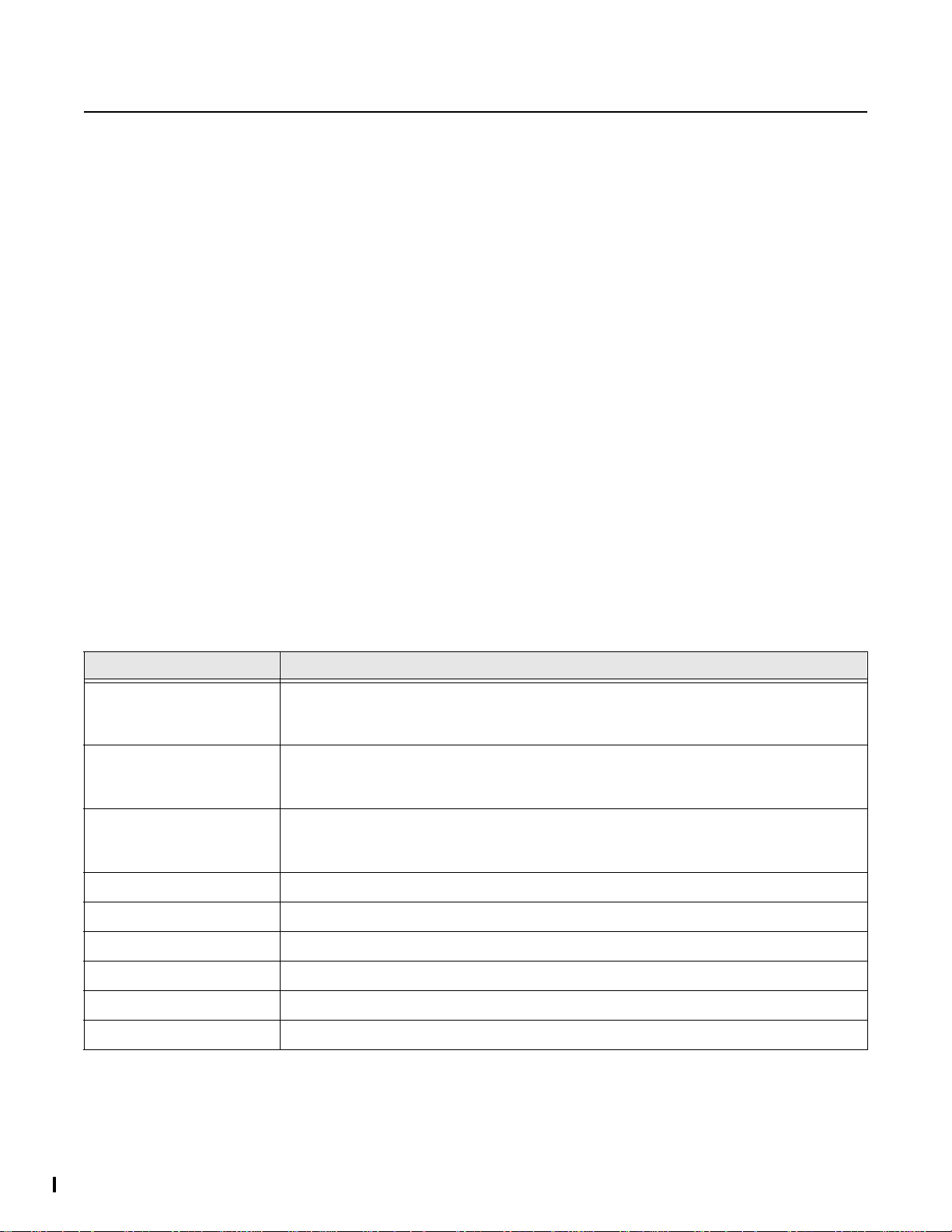
Alarm Sirens and Lights
Exterior and inte rior sirens make 3 dif ferent alarm sounds on the premises, each indicating a different type of alarm. Sirens will
time-out and stop so unding after th e siren timeout (p rogrammable by the installer) . System controlle d lights also indicate the type
of alarm.
Use the following table to understand alarm sounds and controlled lights.
Alarm Type Interior Siren Sound Exterior Siren Sound System Controlled
Lights
Fire (Tem p oral 3) 3 siren pulses then off
for 2 seconds, 3 siren
pulses then off for 2
seconds, . . .
Intrusion On steady On steady Flashing
Emergency Fast on-off _________________ On steady
3 siren pulses then off
for 2 seconds, 3 siren
pulses then off for 2
seconds, . . .
On steady
Panel Indicator Lights
Use the following table to understand the panel indicator lights.
Button When the Button Light is On When the B utton Fla shes
ARM Doors & Windows Doors/Windows armed Doors/Windows armed &
No Entry Delay on
ARM Motion Sensors Motion Sensors armed Motion Sensors armed &
Latchkey on
DISARM System disarmed System subdisarmed
SYSTEM STATUS System trou ble or Op e n Sensor System in alarm
CHIME Doors Door will cause chime _____________________
CHIME Special Motion Motion will cause chime _____________________
LIGHTS Time Activated Light schedule i s on _____________________
LIGHTS Sensor Activated Sensors will cause light to go on _____________________
Numeric Pager
You may program your secur ity sys te m to sen d a numeric message indicatin g sy s tem ac tiv ities to your pager. The syst em wi ll
send the message twice. See “Programming Your System” on pag e11.
Use the following table to determine what the numeric message is reporting.
Reports Numeric Message Reports Numeric Message
Phone Test 101 101 Intrusion 108 108
AC Power Restoral 102 102 Fire 109 109
AC Power Failure 103 103 Disarming 110 110
Latchkey 104 104 Arming 111 111
No Activity 105 105 Fail to Disarm 1 12 112
Panic Code 106 106 Fail to Arm 113 113
Emergency 107 107
6
Page 7

How to Use Your Control Panel
The Control Panel interface consists of 3 columns of buttons. They are: HOME SECURITY, CODE, and HOME CONTROL.
There is a non-medical EMERGENCY button located on the far right.
HOME SECURITY
ARM Doors & Windows.
rity system protection on for all protected doors and windows.
If a door or window is open when you arm the system, it will
be bypassed, meaning not protected. The SYSTEM STATUS
light will be lit.
Press twice to eliminate the preprogramme d entry delay. The
ARM Doors & Windows button bl inks when No Entry Delay is
on.
Press once to turn the secu-
ARM Motion Sensors. Press once to turn protection on
for all intrusion Moti on Sensors. Use when no one is home.
This is usually used in combination with ARM Doors & Win-
dows.
Press twice to activate Latchkey. Latchkey is used to notify
parents if child ren do not ar rive home at a predet ermined time
and disarm the system. The ARM Motion Sensors button
blinks when Latchkey is on.
DISARM. Press once an d enter your access code using the
CODE buttons to turn security protection off. Some sensors,
for example smoke detectors and panic devices, are still active even when the system is disarmed.
SYSTEM STATUS. Press twice to hear information
about your system. If the button is lit, there is a problem with
the system. If the button is blinking, an alarm has occurred.
Press the butto n to hear what is wro ng with the sy stem. See
“System Tests & Tr ouble Beeps” on page 14. Press SYSTEM
STATUS then the 7 - 8 bu tton to turn all lig hts on . Pres s SYS-
TEM STATUS then the 0 - 9 button to turn all lights off.
CODE
There are 5 CODE buttons loca ted on the left si de o f the Control Panel. Each button represen ts 2 numb ers. The top CODE
button is 1 - 2 which means t hat this button is pressed when
entering either 1 or 2. For example, if your access code is 1-
2-3-4 you must press the 1 - 2 button twice and the 3 - 4 button
twice.
If your system includes 24-hour protection sensors on items
such as gun or jewelry cases, you must subdisarm the Control
Panel before accessing these areas to avoid causing an
alarm. To subdisa rm the syst em wh e n it i s alr eady d isar med ,
enter the master access code. The DISARM button will flash
when the Contro l Panel is subdisarmed.
HOME HOME SECURITY
CODE
1 - 2
ARM Doors & Windows
3 - 4
ARM Motion Sensors Motion
5 - 6
DISARM
7 - 8
SYSTEM STATUS
9 -
0
Test Weekly
CONTROL
CHIME
Doors
CHIME
Special
LIGHTS
Time
Activated
LIGHTS
Sensor
Activated
EMERGENCY
8988G12B.DS4
7
Page 8

HOME CONTROL
IIf any of the HOME CONTROL buttons are pressed and a
sensor or module is not associated (programmed) with this
feature the Contro l Pa nel will say,
Function not available
.
CHIME Doors. Press to cau se the Contr ol Panel to be ep
when protected doors or windows are opened.
This is a nice feature to use if you’re busy in one part of
your home and you want to know when family membe rs
are going in and out of your home.
CHIME Special Motion. Press to cause th e Control
Panel to beep when Motion Sensors detect movement within
a specific area. These Motion Sensors are not used for intrusion protection.
If you have Motion Sensors located in areas such as in a
patio area or at the front door and you want to know when
someone is approaching these areas, you would use this
feature.
LIGHTS Time Activated. Press to enable system con-
trolled lights to turn on and off at scheduled times.
An example is turning your living room lights on at 7 pm
and off at 10 pm.
LIGHTS Sensor Activated. Press to have specially
programmed sensors turn on lights for 4 minutes when sensors are tripped.
An example is using an outdoor Motion Sensor at t he front
door. When the Motion Sensor dete c ts movement it will
cause the light at the front door to turn on.
You may also program the star button on the KeyChain
Touchpad to turn on a light for 4 minutes. The KeyChain
Touchpad star key will always work, even when sensor
activated lights are disabled.
EMERGENCY
Press EMERGENCY for 2 seconds or twi ce qu ickly to call th e
central monit oring station and notify them of a no n-medical
call for help.
HOME HOME
SECURITY
CODE
ARM
Doors &
Windows
ARM
Motion
Sensors Motion
DISARM
SYSTEM
STATUS
1 - 2
3 - 4
5 - 6
7 - 8
9 -
Test Weekly
0
CONTROL
CHIME Doors
CHIME
Special
LIGHTS Time Activated
LIGHTS Sensor Activated
EMERGENCY
8988G12B.DS4
8
Page 9

How to Use An Off-Site Phone for Remote Phone Control
You may use an off-site phone to arm /disarm your Control
Panel, toggle lights, check system status, or conduct an audio
session (ask y our install er if you ha ve this fe ature). To ga in access to the Control Panel:
1. Call the Control Panel and let th e ph on e rin g twic e then hang up.
2. Wait 10-40 seconds and call the Control Panel again.
3. The Control Panel should answer on the first ring.
You won’t hear any prompt when the system answers.
4. Press the * button on your telephone and you will hear
system activ ated
At this point you may perform the actions listed in the first
paragraph of this page.
For example, to check system status:
Press * + CODE + # + 1 on your telephone. CODE is the 4
digit master code programmed into your Control Panel.
Note: Press * + CODE + 99 to hang up or your security
system site phone may be busy for up to 90 seconds after
your disconnect.
Note: If you are interactive with your Control Panel and the
panel hangs up on you, the system is calling in a report to the
central monitoring station or a pager, due to an action made
by you or someone at the security system site.
The following table identifies the phone commands to be used
when using remote phone control.
.
Phone Commands for Remote Access
Control Panel Function Phone Command
DISARM * + CODE + 1
ARM Doors/Windows * + CODE + 2
ARM Doors/Windows with
No Entry Delay
ARM Motions * + CODE +3
ARM Motions with Latchkey * + CODE + 3 + 3
ARM Doors/Windows and
Motions
ARM Doors/Windows with
No Entry Delay an d Motions
with Latchkey
Toggle Lights * + CODE + 0
System Status * + CODE + # + 1
Audio Session * + CODE + 5 + X (X = a
* + CODE + 2 + 2
* + CODE + 2 + 3
* + CODE + 2 + 2 + 3 + 3
command from the audio
session command set).
See Table on pa ge 9
2-Way Voice Audio Session
An audio session may be conducted from off site. You can call
the security system site and talk to the people present and
they can talk to you through the speaker and microphone on
the Control Panel.
Note: Ask your installer if you have t his f eatur e avail able
to you.
Do the following to cond uct an audio session:
1. Follow the instructions above for Remote Ph on e Control to gain access to the Control Panel.
2. Press * + CODE + 5 on the phone to start the audio session.
3. Press 1 to speak or 3 to listen.
If you press 3 to listen, without first pressing 1 to speak,
you will notice a 5 second delay before you can hear the
Control Panel’s surroudings.
See the following table Audio Session Command Set for
the commands that can be used from an off site phone.
4. Press 9 + 9 to hang up.
Hang Up * + CODE + 99
CODE = 4 digit master access code
Audio Session Command Set
Phone
Button(s)
1 or 0 Speak
3 or 6 Listen
7 Initiates timed session
88 Termina tes session with call back
99 Termina tes session with no call back
Audio Session
9
Page 10

How to Use Your Touchpads
Touchpads are used to co ntrol the security sys tem from any location with in or near your home. They hav e additional home contr ol
features such as light and appliance control. When using the Touchtalk 2-Way RF Touchpad, beeps and voice feedback will be
heard from this touchpad and not from the Control Panel.
Remote Handheld Touchpad and Touchtalk 2-Way RF Touchpad
SYSTEM STATUS Press once to hear information about your system. See “System
Tests & Trouble Beeps” on page 14.
SYSTEM
STATUS
ARM
Doors &
Windows
ARM
Motion
Sensors
DISARM
1
4
7
On
EMERGENCY
2
5
89
-
d&sre s Hol hBtoeKy
8988G07B.DS4
KeyChain Touchpad
ARM Doors & Windows Press once to turn the securi ty sy s tem protection on for all
protected doors and windows.
Press twice to eliminate the preprogrammed en try delay.
ARM Motion Sensors Press once to turn protection on for all Motion Sensors. Use
when no one is home. This is usually used in combination with ARM Doors & Windows.
Press twice to activate th e La tc hkey feature.
DISARM Press once and enter your access code using the NUMERIC buttons to turn
3
6
security protection off. To subdisarm the system, enter the master access code.
ON Light button Press twice quickly to activate all lights controlled by the security
system. You ma y turn on spec ific ligh ts and a pplian ces by p ressin g this bu tton onc e and
entering the unit number of a light or appliance using the NUMERIC buttons.
Off
OFF Light button Press twice quickly to turn off all lights. You may turn off specific
lights and appliances by pressing this button once and entering the unit number of the
light or appl iance.
sP
EMERGENCY Press both EMERGENCY buttons for 3 sec onds to cau se the system to
call a central monitoring station to report a non-medical emergency.
LOCK Press once to arm doors and windows.
LOCK Press twice to arm doors, windows, and Motion Sensors.
LOCK Press 3 times to arm doors, windows, Motion Sensors, and to activate the
Latchkey option.
10
Entering your home If your installe r programme d the KeyChain Touchpad with no entry
delay, and you armed the sys te m with the KeyCha in Touchp ad , yo u must disarm your
system from outside of the home to avoid causing an alarm.
Exiting your home You have at least 5 seconds and up to 120 seconds (depending on
installer programming) to leave without causing an alarm.
LOCK and UNLOCK Press both buttons simultaneously for 3 seconds to send an
intrusion, silent, or non-medical emergency alarm to the central monitoring station.
8348G03A.DS4
UNLOCK Press to disarm your security system.
LIGHT Press to turn system controlled lights on or off.
STAR Press to open or clos e your gar age door, if pro grammed , or your sys tem may b e
programmed to turn on a light using this button.
For any keypress on the KeyChain Touchpad, hold the button until the indicator
light blinks.
Page 11

Programming Your System
What You Can Change:
Options:
Press Add in the START MENU and follow the vo ice promp ts
to turn an option on.
Press Delete in the START MENU to turn an option off.
Option 01 - Panel Beeps
Panel Beeps are any be ep s (including chime bee p s) that
come from the Control Panel. Panel Beeps, except for
alarm sirens, may be disabled. See “Panel Beeps” on
page 5.
Option 02 - Panel V oic e
Panel Voice may be disabled, exce pt for status me ssages,
open sensor responses, and when in program mode.
Option 03 - Latchkey Time
Adding this option allows you to program Latchkey Time.
Latchkey is used to notify parents if children do not arrive
home at a predetermined time and disarm the system.
Option 36 - Sensor Activated Light Lockout Start Time
Option 37 - Sensor Activated Light Lockout Stop Time
The Control Panel will not turn on a light which is activated
by a sensor, even if sensor activated lights are enabled,
between the programmed star t time (option 36) and the
programmed stop time (option 37).
Both options must be programmed for this feature to work.
The LIGHTS Sensor Activated bu tton must be lit for lights
to turn on.
Option 41 - Voice Chime
The Control Panel will verbally announce which chime sensor has been tripped if the chime feature is on.
time is programmed by the user - Option 03. Latchkey
must be enabled when arming.
• Phone Test - A phone test report is called in when a
phone test has been performed.
• Disarming - A disarming report is called in when the
system is disarmed. This option is programmed by your
installer.
• Arming - An arming report is called in when the system
is armed. This option is programmed by your installer.
• Fail to Disarm - A fail to disarm report is called in when
the system is not disarmed by th e time pro gr ammed by
the installer.
• Fail to Arm - A fail to arm report is called in when the
system is not armed by the time prog ra mmed by the
installer.
• AC Power Failures - An AC power failure is called in 15
minutes after loss of power.
• AC Power Restoral - A restoral will be reported when
power is restored.
• Alarms - Alarm resports include: Emergency, Intrusion,
and Fire.
Sensor Test or Phone Test . A sensor test or phone
test can be perf ormed by foll owing the instru ctions given in the
section labeled “Manual Tests--What You Need to Test” on
page 15 of this manual.
Access Codes. Your security sys tem ha s a master
access code, ac ce ss codes 1-5, and a pa nic code. The master code is used for disar ming and programmi ng your system.
Access codes 1-5 are generally us ed fo r ch ildren or as temporary codes for a babysitter or service personn el and may
be used only for disarming. The panic code may be entered
to disarm or subdisarm the system in a non-medical emergency situation. The Co ntrol Panel will call the central statio n,
but there will be no indication of an alarm at the Control
Panel.
Option 42 - Speaker Level
Turn th e Cont rol Pan el sp eake r level to t he high voic e lev el
when the option is turn ed on or tu rn the s peaker le vel to the
low voice level when turned off.
Option 43 - Pager Phone Number
Up to 22 digits, including pa us es , may be programmed for
the pager phone number.
Add 3 or 4 pauses to the end of the phone number to
ensure the complete pager message will be received.
Press the Test button to program a pause into the phone
number.
The Control Panel will call the pager to indicate:
• No activity - The no activity time period is programmed
by your install er. A no activity alarm is called in if th e programmed amount of time passe s, the Control Panel is
subdisarmed, disarmed, or doors and windows armed,
and no activity has occurred (a key has not been
pressed or a sensor has not been tripped). Tripping of
non-intrusion chime sensors is not considered activity.
• Latchkey - A latchkey report is called when the system
is not disarmed by a predetermined time. The latchkey
Note: Because different codes can be entered using the
same button presses you have to use caution when programming the panic code. You need to ensure that the panic code
does not use the same button presses as other access
codes. For example if the master code is 1234, do not program the panic code to be 22 44 . The Control Panel would
interpret these codes to be the same code.
Time Activated Lights. Lights may be put on a time
schedule.
Entry/Exit Activated Lights. Lights will tu rn on for th e
delay period .
Sensor Activated Lights. Lights will turn on for 4 min-
utes after a sensor is tripped.
Set Clock. If the panel loses power, the clock must be set.
House Code. The house code progra mmed into the
panel should match the housecode set on lamp, appliance,
and garage door modules.
11
Page 12

Programming Using Panel Decals (Upper Decal and Lower Decal)
The programming dec als ar e vis ib le whe n you open t he Co ntrol Panel cov er. Th ese de cals are de sign ed to make syst em programming easier for you. Always begin by choosing a button from the START MENU. Follow the voice pr ompts and flow arro ws
to complete the desired task. Notice the button flow diagrams under Instruction Summary to the right of the buttons and on
the lower
decal.
8988G37D.DSF
12
8988G38A.DSF
Page 13

Step by Step Programming Instructions
8988G25B.DS4
8988G45B.DS4
Delete Access Code
Delete
Use the following instruc tions to acce ss the programmin g buttons and programming decals.
1. Open the Control Panel Cover by pressing the plastic latch on the top of the Control Panel.
When you open the cover you will immediately be
prompted by the Control Panel voice to use the red numbered keys to enter your ID.
2. Enter Your Access Code.
The Master access code is 1-2-3-4 when the panel is
shipped. You should change it to a code known only
by you.
3. The system voice will pr ompt you to begi n with the
START MENU. The START MENU is located on the left
side of the upper decal.
The START MENU includes the following buttons:
Add
Delete
Cancel
Test
Clock Set
Press the appropriate button.
4. After pressing a b utto n on th e START MENU the system
voice will promp t you to then use the MAIN MENU.
The MAIN MENU includes the following buttons:
Option #
Sensor/Remote
Access Code
Light Control
Press the appropriate button.
Depending on the button you pressed, the system will prompt
you to continue by pressing other buttons on the panel.
7. Close the Control Panel cover .
How to Delete an Access Code
1. Open the cover of the Control Panel.
2. The panel voice p rompts you to
to enter 4-digit ID.
using the red numbered keys.
3. The panel voice prompts you to
START MENU.
MENU.
4. The panel voice prompts you to
MENU.
MENU.
5. The panel voice responds with
Press the Access Code button on the MAIN
Enter your master access code
Press the Delete button on the START
Use red numbered keys
Please select fro m
Select from MAIN
Access Code 1, press
again for next access code or DONE to select or CANCEL to quit.
the next access code. When you hear the access code
you wish to delete, press the DONE Button. The panel
voice responds with
6. Close the Control Panel cover .
Press the access code button again to hear
Access Code X deleted
.
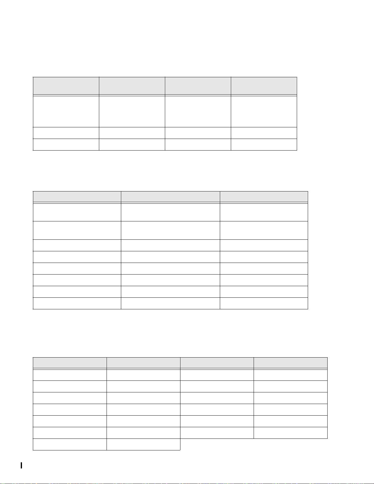
Options
The following is a table of options you can change. See “What
You Can Change:” on page 11 for a description of these options.
Option # Add Delete
How to Change an Access Code
1. Open the cover of the Control Panel.
2. The panel voice prompts you to
to enter 4-digit ID.
using the red numbered keys.
3. The panel voice prompts you to
ST ART MENU.
MENU.
4. The panel voice prompts you to
MENU.
MENU.
5. The panel voice responds with
for next access code or DONE to select or CANCEL to
quit.
access code. When you hear the access code you wish
to change press the DONE Button
6. Enter 4 new numbers using the red numbered keys.
Use red numbered key s
Enter your master access code
Please select from
Press the Add button on the START
Select from MAIN
Press the Access Code button on the MAIN
Master Code, pr ess again
Press the access code button again to hear the next
.
1 - Panel Beeps On Off
2 - Panel Voice On Off
3 - Latchkey Time 12am - 11:59 pm Off
36 - Sensor Activated
Light Lockout Start Time
37- Sensor Activ ated Light
Lockout Stop Time
41 - Chime Voice On Off
42 - Speaker Volume
High/Low
43 - Pager Phone Number Up to 22 digits* Off
* See “Option 43 - Pager Phone Number” on page 11
12am - 11:59 pm Off
12am - 11:59 pm Off
High Low
13
Page 14

System Tests & Trouble Beeps
Automatic Control Panel Testing--What the System Tests for You
Your security system is able to automatically test itself for:
• Power failures
• Low batteries
• Non-working sensors
• Communication troubles with the Cen tral Monitoring Station
Trouble Beeps. When your security system detects one
of the problems above, interior sirens sound trouble beeps
rapidly six times, and then again every minute, until the trouble
condition is corrected.
If you do a status check by pressing the SYSTEM STATUS
button twice or chang e the sys tem from being armed to dis armed or disarmed to armed, the beeps will stop. If the problem is not corrected, beeps start again 4 hours later.
Silencing Trouble Beeps
Pressing the SYSTEM STATUS button twice or
changing from armed to disarmed or disarmed to
armed while th e system has a troub le condition
stops the trouble beeps. Trouble beeps begin again
4 hours later, in some ca ses, unless the tro ub le
condition is corrected.
AC Power Failure. This condition occurs if your security
system has been accidentally unplugged or if there has been
an AC power outage. The backup battery will take over. If AC
power is not restore d within 15 seconds, th e Control Panel wil l
go dark and alert you with trou ble bee ps. If y ou pre ss any button, the display will light and pre ss in g SYSTEM STATUS
twice will confirm the AC power failure. If AC power is not restored within 15 minutes, the system will call the central monitoring station (if programmed by installer). The backup
battery, if fully charged, will last for 18 - 24 hours with no AC
power.
trouble. Perform sensor tests. It may be necessary for you to
call your security system dealer if the problem co nt inues.
Sensor Low Battery. This condition occurs if a system
sensor has a low battery. The sensor may still be communicating with the Control Panel. Trouble beeps will start and the
SYSTEM STATUS button will light. Press the SYSTEM STATUS button twice to hea r which sensor( s) have troub le. It may
be necessary for you to call yo ur secu rit y system de ale r to resolve this pro blem. Some se nsor batte ries can be re placed by
the homeowner.
Fail-To-Communicate. This cond ition occu rs if yo ur se-
curity system cannot communicate to the central monitoring
station. Your s ystem wi ll try to rep ort to the ce ntra l monito ring
station 8 times before it tells yo u th er e is a Fail-To-Communicate problem. Trouble be eps will sta rt an d the SYSTEM STA-
TUS button will light. Press the SYSTEM STATUS butt on
twice to hear the trouble messag e. It may be nece s sa ry for
you to call your security system dealer if the problem continues.
Sensor Open. This condition occurs if a door or windo w is
open, or a system sensor has been disturbed or tampered and
not reset prop er ly. Fo r ex amp le , a Mo tio n Sen so r may b e of f
the wall or a Door/Window Sensor cover may have been removed from the sensor. Your system will indicate this condition to you by causing the SYSTEM STATUS button to light.
When you press this button twice, the system responds with
Sensor # Name open
sensor. If this condition continues call your security system
dealer
. Correct the proble m by res e tting the
Option 50 Detected. Call your security sy stem dealer.
Module 1 or 2 Failure. Call your security system deal-
er.
System Access Alarm. The Control Panel cover was
opened while the system was armed.
System Battery Failure. This condition occurs if the
emergency backup battery has been drained. Trouble beeps
will start and the SYSTEM STATUS button will lig ht. Press the
SYSTEM STATUS button twice to hear the tr ouble me ssag e.
If your AC power is not wor king, yo ur secur ity syste m will shut
down once the battery is drained. The Control Panel battery
should be replaced once a year if using a 9V Ultralife bat te ry .
Sensor Failure. This condition occu rs if a sensor is not
communicating with the Control Panel. Trouble beeps will
start and the SYSTEM STATUS button will light. Press the
SYSTEM STATUS button twice to hear which sensor(s) have
14
Clearing System Status
If a trouble condition is corrected, press the SYSTEM
STATUS button twice, liste n to the statu s message, th en
disarm the system to clear system status. If the trouble
condition was a low CPU battery , perform a sensor test.
The SYSTEM STATUS button should turn off if all trou-
ble conditions have been corrected.
Page 15

Manual Tests--What You Need to Test
As an added safeguard, there are system tests you should do
yourself on a regular basis. The Control Panel cover in the
lower left corner reminds you to
Sensors
You can test sensors one at a time to make sure they are
sending strong sig nals to the Contr ol Pa nel (see Tes ting Se nsors paragr aph).
Communication
You can also test the commun ication between your system
and the Central Monitoring Station (see Testing Co mmunication paragraph).
TEST WEEKLY
.
Testing Sensors
You should test the security system at least once each week.
To perform the sensor test:
1. Open the Control Panel Cover.
2. Enter the master a ccess code.
3. Press the Test button once, the Control Panel will say
Sensor Test
4. Press the DONE button.
The panel will voice pro mpt you with a list of your programmed
sensors that you need to test. The panel will start with sensor
1 and say
When you trip a sensor and it communicates successfully it
will be removed fr om the li st. You ma y t rip th e se ns ors in an y
order. The sensor tes t has a 4 minute t ime out that re sets with
each sensor trip.
After all sensors have bee n su cc essfully tested, th e Control
Panel will say
DONE. The Control Panel will say
If any of the sensors did not test successfully and you want to
terminate the test, press DONE. The Control Panel will say
Sensor test canceled or failure
security dealer .
Use the following table to trip sensors.
Sensor Tripping Instructions:
Sensor Do This
Door/Window Open the secured door or win-
Freeze Apply ice to the sensor. Do not
Water Press a wet rag or wet finger
Carbon Monoxide
Alarm
.
Test sensor 1, sensor name.
Sensor test complete, press DONE
Sensor test ok
. If a sensor test fails, call your
dow
allow the sensor to get wet
over both of the round, goldplated termina ls on the underside
of the sensor
Unplug the CO Alarm. Plug it
back in, then press the TEST/
RESET button until the unit
beeps 6 times
. Press
.
Sensor Tripping Instruct ions:
Sensor Do This
Glass Guard Tap the glass 3 or 4 inches from
the sensor
Motion Sensor Avoid the Motion Sensor’s view
for 5 minutes, then enter its view
Rate-of-Rise Heat
Detector
Shock Tap the glass twice, away from
Smoke Press and hold the test button
Panic Buttons Press and hold the appropriate
KeyChain Touchpad
Remote Handheld
Touchpad and
Touchtalk 2-Way
RF Touchpad
SWS Unplug the SWS, plug the unit
Rub your hands together until
warm, then place one hand on
the detector for 30 seconds
the sensor. Wait at least 30 seconds before tes tin g again
until the system sounds transmission beeps
panic button( s) for 3 seconds
Press and hold LOCK and
UNLOCK simultaneously for 3
seconds
Press and hold the 2 EMERGENCY buttons simultaneously
for 3 seconds
back in
Testing Communication
Test communication with your central monitoring station and
the pager at least on ce per week to make sure yo u have the
proper telephone connection between your system and the
central monitoring station.
To perform a phone test:
1. Open the Control Panel cover.
2. Enter the master acces s code.
3. Press the Test button twice, the Control Panel will say
Phone Test
4. Press the DONE button. The Control Panel will say
successful the Control Panel will say
minutes. The Control Panel will say
times if you have a pager. Your pager will display 101 101 if
the phone test to the pager was successful. If the test is unsuccessful, the SYSTEM STATUS button will light and the
Control Panel will say
minutes. If a phone te st fai ls, ca ll you r sec urity syst em dea ler.
NOTE: If your system is not connected to a central monitoring station, and you don’t use a pager, you won’t be
able to perform the phone test.
.
Phone test is on
Phone test is on
Phone communicat ion fa ilur e
twice. If the test is
Phone test ok
within 3
three
within 10
15
Page 16

Your Emergency Evacuation Floor Plan
Planning for Emergencies
This section describes what you can do to plan ahead for an
emergency:
• Emergency Planning
• Your Floor Plan
Emergency Planning
Since an emergency is a lways une xpected, you shoul d devel-
op plans to help prepare for a variety of emergency situations.
Periodically discuss and rehearse emergency plans to include
the following:
• Understand how to use your security system
• Know the normal state of doors and windows; open,
closed, or locked.
• Escape fast! (Do not stop to pack.)
• Use a different escape route if closed doors feel hot to
the touch.
• Crawl and hold your breath as much as possible to help
reduce smoke inhalation during your escape.
• Meet at a designated outdoor location.
• Emphasize that no one should return to the premises if
there is a fire.
• Notify the fire depa rtme nt from a neighbor’s phone.
• Emphasize that no one should enter the premises if they
hear sirens in th e house.
• If you arrive at the premises and hear sirens, do not
enter. Call for emergency assistance from a neighbor’s
phone.
Your Floor Plan
Use the following guidelines when drawing your floor plan:
• Show all building levels.
• Show exits from each room (two exits per room are recommended).
• Show the location of all security system components.
• Show the location of any fire extinguishers.
16
Page 17

Alarm System Limitations
Not even the most advanced alarm system can guarantee protection against burglary, fire, or environmental problems.
All alarm systems are subject to pos s ib le co mpromise or failure-to-wa rn for a va riety of reasons.
• If sirens are not placed within hearing ra nge of persons sleep in g or in remote parts of the premises, or if they are place d
behind doors or other obstacles.
• If intruders gain access through unprotected points of entry or areas where sensors have been bypassed.
• If intruders have the technical means of bypassing, jamming, or disconnecting all or part of the system.
• If power to sensors is inadequate or disconnected.
• If freeze or any environmental sensors are not located in areas where the appropriate condition can be detected.
• If smoke does not reach a Smoke Sensor. For example, Smok e Sen sors cannot detec t smo ke in chimney s, wall s, roofs , or
smoke blocked by a closed door. Sensors may not detect smoke in other levels of the building. Sensors may not warn in
time when fires are cause d by smoking in bed, explo si ons, improper storag e of flammables, overloaded electrical circ uits,
or other hazardous conditions.
• If telephone lines are out of service. Telephone lines are also vulnerable to compromise by any of several means.
Inadequate maintenance is the most common cause of alarm failure. Therefore, test your system at least once per week to be
sure sensors, sirens, an d pho ne commu ni ca tions are all working corre ct ly.
Although having an alar m sys tem may make you eligible for red uc e d insurance premiums, the system is no substitute for ins ur ance.
WARNING! Security system devices cannot compensate you for the loss of life or property.
Service
If you have any questions about your security system or if you ever need service, please contact your security consultant.
Company Name ___________ _ _________
Phone Number _____________________
Address _____________________
______________ _______
17
Page 18

Numerics
2-Way Voice Audio Session 9
2-Way Voice On-Board 4
A
AC Power Failure 11, 14
AC Power Restoral 11
Access Code, change 13
Access Code, delete 13
Access Codes 11
Alarm 6
Alarm Siren s and Lights 6
Alarm System Limitations 17
Alarm Type 6
Alarms 11
ARM Doors/Windows 5, 7, 9, 10
ARM Doors/Windows & Motion Sensors 5, 9
ARM Doors/Windows with No Entry Delay 9
ARM Doors/Windows with No Entry Delay and Motions with
Latchkey 9
ARM Motion Sensors 5, 7, 9, 10
ARM Motions with Latchkey 9
Arm with Doors or Windows Open 3
Arming 11
audio session 9
Audio Verification Module 4
Audio Verification Set 9
B
battery failure 14
Beeps 5, 14
C
Canceling Accidental Alarms 3
Change an Access Code 13
CHIME Doors 5, 8
CHIME Special Motion 5, 8
Clearing System Status 14
CODE 7
Communication test 15
Control Panel 4
D
delay, entry 5
delay, exit 5
Delete an Access Code 13
DISARM 5, 7, 9, 10
Disarm 11
Door/Window Sensors 4
E
Emergency 5, 6, 8, 10
Emergency Evacuation Floor Plan 16
Entry delay 5
Entry/Exit Activated Lights 11
Exit delay 5
F
Fail to Arm 6, 11
Fail to Disarm 6, 11
Fail-To-Communicate 14
FCC Notices 2
Fire (Temporal 3) 6
H
HOME CONTROL 8
HOME SECURITY 7
House Code 11
I
Indoor Motion Senso rs 4
Intrusion 6
K
KeyChain Touchpad 10
KeyChain Touchpads 4
L
Latchkey 7, 9, 11
Light 10
Light button 10
Light Lockout 11
LIGHT ON/OFF 10
light unit number 10
light unit numbers 4
LIGHTS Sensor Activated 8, 11
LIGHTS Time Activated 8
Lights Time Activated 11
limitations 17
LOCK 10
M
Master Access Code default 5
Messages to the Owner 3
messages, trouble 14
Module 1 or 2 Failure 14
Modules 4
motion sensors 4, 5, 6, 7, 9
N
No activity 11
No Entry Delay 7
O
Option 01 - Panel Beeps 11
Option 02 - Panel Voice 11
Option 03 - Latchkey Time 11
Option 36 - Sensor Activated Light Locko ut St ar t Time 11
Option 37 - Motion Activated Light Lock out St op Time 11
Option 41 - Voice Chime 11
Option 42 - Speaker Level 11
Option 43 - Pager Phone Number 11
Option 50 Detected. 14
Option Table 13
Outdoor Motion Sensors 4
P
pager 6
pager reports 6, 11
Panel Beeps 5
Panel Indicator Lights 6
Panel Voice Messages 5
panic code 3
Phone Commands for Remote Access 9
Phone Test 11, 15
Programming Decals 12
Programming Instructions 13
R
Remote Access 9
Remote Handheld Touchpad 10
Remote Handheld Tou chpad and Touchta lk 2-Way RF Tou ch-
pad 4
Reports, pager 6
S
Sensor Activated Lights 8, 11
Sensor Failure 14
Sensor Low Battery 14
18
Page 19

Sensor Open 14
Sensor Test 5, 11
sensor testin g 15
Sensor Tripping Instructions 15
Sensors 4, 15
Service 17
Set Clock 11
Silencing Trouble Beeps 14
Sirens 6
Smoke Sensors 4
STAR 10
subdisarm 3, 7
System Access Alarm 14
System Battery Failure 14
SYSTEM STATUS 6, 7, 10, 14
System Status 9
SYSTEM STATUS, clearing 14
System Tests 14, 15
T
Table Alarm Type 6
Table Audio Verification Set 9
Table Numeric Pager 6
TABLE OF CONTENTS 3
Table Options 13
Table Panel Beeps 5
Table Panel Indicator Lights 6
Table Phone Commands for Remote Access 9
Table Sensor Tripping Instructions 15
test phone 15
Testing Communication 15
Testing Sensors 5, 11, 15
Time Activated Lights 8, 11
Toggle Lights 9
touchpads 10
Touchtalk 2-Way RF Touchpad 10
Trouble Beeps 5, 14
trouble beeps, silencing 14
Trouble Mess a ges 14
U
unit numbers 4
UNLOCK 10
19
Page 20

How to . . .
Arm the system
– Doors & Windows
Arm the system
– Motion Sensors
Arm the system
– Doors/Windows & Motion Sensors
Activate No Entry Delay
Activate the Latchkey feature
CONTROL PANEL
ARM
Doors &
Windows
ARM
Motion
Sensors
ARM
Doors &
Windows
ARM
Doors &
Windows
ARM
Motion
Sensors
ARM
Motion
Sensors
Press Twice
Press Twice
Quick Reference Table
REMOTE HANDHELD &
Touchtalk 2-Way RF
TOUCHPAD
ARM
Doors &
Windows
ARM
Motion
Sensors
ARM
Doors &
Windows
ARM
Doors &
Windows
ARM
Motion
Sensors
ARM
Motion
Sensors
Press Twice
Press Twice
KEYCHAIN TOUCHPAD
Press twice
Press once if
programmed
Press 3 times
REMOTE PHONE CONTROL
Press + Master Code + 2
*
Press + Master Code + 3
*
Press + Master Code + 2 + 3
*
Press + Master Code + 2 + 2
*
Press + Master Code + 3 + 3
*
Disarm the system
Subdisarm the system
Send an alarm to the
Central Monitoring Station
Check the system status
Set doors to Chime
Set Special Motion Chime
Set lights to time activated
Set lights to sensor activated
Open a garage door or turn
on special lights
Toggle lights
Lights on
Lights off
DISARM
Master Code
EMERGENCY
SYSTEM
STATUS
CHIME
DOORS
CHIME
Special
Motion
LIGHTS
Time
Activated
LIGHTS
Sensor
Activated
SYSTEM
STATUS
SYSTEM
STATUS
+ Access Code
Press & hold
for 3 seconds
Press Twice
7 – 8
+
9 – 0
+
DISARM
Master Code
Press both EMERGENCY buttons.
Press & hold for 3 seconds.
SYSTEM
STATUS
+ Unit #
+ Access Code
Press Once
Press Twice
Press Twice
Press & hold
for 3 seconds
Press & hold
Press + Master Code + 1
*
Press + Master Code + 1
*
Press + Master Code + + 1
*
Press + Master Code + 0
*
#
466-1575
 Loading...