

Page 1

Concord Express U ser's G uide
466–1667 Revision B
Getting to Know Your Security System 3
Overview 3
Communicating with the Panel 3
Instructing the Panel 4
How Your System Communicates with You 4
Fire and Smoke Alarms 4
Clearing Smoke Sensors 4
What Happens When There is an Alarm 4
Arming Your System 4
Level 1—OFF 4
Arming Level 2—STAY 5
Arming Level 3—AWAY 5
Test System Weekly
A
B
C
D
press both
press both
press both
Off
No Delay
415
Features
7
Status
*
Stay
Away
23
Silent
Pager
6
System
Menu
8
9
Lights
Bypass
0#
Auxiliary Panic Alarm 10
Siren Time-out 10
Access Codes 10
System Master Code 10
Regular User Codes 10
Using the Programming Menus 10
Programming Access Codes 10
Setting the Time and Date 11
Adjusting System Sounds and Touchpad Brightness 11
Arming Your System Silently 11
Adjusting the Touchpad Beeps 12
Adjusting the Touchpad Display Brightness 12
Keychain Touchpad Arming 5
Quick Arm 5
Quick Exit 5
Using the Chime Feature 6
Preventing Accidental Alarms 6
Exit and Entry Delay Times 7
Extended Delay 7
Exit Extension 7
No Delay—For Instant Alarm 7
Auto STAY Arming Feature 8
Arming While a Door or Window is Open 8
Bypassing a Sensor Directly 8
Bypassing a Sensor Indirectly 8
Was the Bypass Successful? 8
Checking the Status of Your System 9
Short System Status 9
Full System Status 9
System Alarm Sounds 9
Panic Alarms 9
Fire Panic 9
Police Panic Alarm 9
Notification by Pager 12
Pager Messages 12
Streamlining the Page 13
Opening and Closing Reports 13
Latchkey Paging 14
No Activity Feature 14
Using the Panel Download Feature 14
System Information 14
Testing the System 15
Automatic Test Features 15
Manual Tests 15
Troubleshooting 16
Trouble Beeps and Trouble Messages 16
Appendix A: User Sheets 18
Appendix B: Planning for Emergencies 21
Appendix C: Programming Menus 23
Index 31
Page 2

Commands at a Glance
To do this: Press:
Disarm the system.
Cancel an accidental alarm.
Arm to Level 2 —STAY.
Arm to Level 3—AWAY.
Send a police alarm. Press and hold both POLICE
Send an auxiliary alarm. Press and hold both AUXILIARY
Send a fire alarm. Press and hold both FIRE
Arm system with No Delay.
1 + Code
2 + Code
3 + Code
buttons for 2 seconds.
buttons for 2 seconds.
buttons for 2 seconds.
2 + Code + 4 or
3 + Code + 4
Arm system to send a
Latchkey page.
Bypass a sensor.
2 + Code + 6 or
3 + Code + 6
Indirectly: 2 + Code + ƒ or
3 + Code + ƒ
Directly: ƒ + Code + Sensor Number
Arm system silently.
5 + 2 + Code or
5 + 3 + Code
Check the system status.
Turn Ch ime on/off.
Check alarm memory.
Initiate a phone test.
Initiate a sensor test.
‚
7 + 1
7 + 6
8 + Code + 2
8 + Code + 3
Page 3

3
1
2
3
6
9
8
5
4
7
ST
0
BY
OFF
STAY
AWAY
NO DELAY
CHIME
STATUS
BYPASS
COMMAND
GETTING TO KNOW YOUR SECURITY SYSTEM
This manual describes how to operate your system. It describes
basic arming and disarming commands as well as how to program
system features.
The dealer or installer may have already discussed the details of
your system with you. Record your system details in the User
Sheets located in Appendix A.
Overview
Y o ur secur ity system is made up of different parts. Each plays a
special role in the syst em’s ope ration:
The panel is at the heart of your system. It
stores the i ntellig ence to mo nitor al l the sensors
and devices in the system. The panel is the
piece of equipment that activ a t es sir e ns an d initiates a call to the central s tatio n in an alarm si tuation.
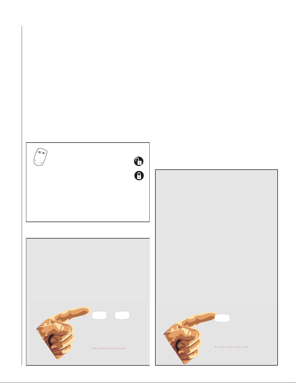
Touchpads are used to arm, disarm, and program your system.
Y o ur sy stem may use a wal l -
mounted touchpad that
looks like this:
Q u ic k G u id e
Disarm System/Can cel Alarm
Press 1 + CODE.
Arm to STAY
1
Close all protected doors and windows.
2
Press 2 + CODE.
3
Press 4 to arm delay do ors instantly,
if desired.
Arm to AWAY
1
Close all protected doors and windows.
2
Press 3 + CODE.
3
Ex it p r em is es th r o u g h d ela y d o o r.
Zone/Sensor Num ber
01
02
03
04
05
06
07
Byp ass Se nso rs
1
Arm sy stem to de sired level.
2
Press BYPASS + CODE + Sensor No.
Turn CHIM E O n/O ff
1
Ma ke su re sy stem is d isarm ed .
2
Press 7 + 1 to tu rn C H IM E o n or o ff.
Program User Settin gs
1
Ma ke su re sy stem is d isarm ed .
2
Press A or B to sc roll throug h m en us.
Press # to select option or accept entry.
Press to deselect option or cancel entry.
Press 1 fo r O F F ; p ress 2 fo r O N ;
press 0 - 9 fo r o the r en tries.
08
09
10
11
12
13
14
Test System Weekly
A41
B
C
D
System is OK
Stay
Away
Off
3
2
press both
Silent
Pager
No Delay
5
Features
7
Status
*
6
System
Menu
8
9
Lights
Bypass
0#
press both
press both
Your system may also use wireless,
handheld touchpads that can be carried
from room to room.
Key ch ain touchpads are also wireless and are
handy for simple arming and disarming functions. Key chai n t ouch pads can be carried off-site.
The installer can program the keychain touchpad
to send a Police or Auxiliary panic alarm.
Wireless panic button touchpads are dedicated to sending one signal only—usually a
Police or Auxiliary panic alarm. Panic button
touchpads are usually kept near the user.
Door and window sensors protect the perimeter
of your home by alerting the panel when a door or
window is opened.
Motion detectors in hallways or rooms detect a person
moving across the field of detection.
Environmental sensors such as smoke and heat
detectors remain al ert f o r the presence of fire or
carbon monoxide 24 hours a day.
Stay
Or this:
Test System Weekly
A41
press both
B
press both
C
press both
D
No Delay
Features
Status
Off
7
*
Away
3
2
Silent
Pager
5
6
System
Menu
8
9
Lights
Bypass
0#
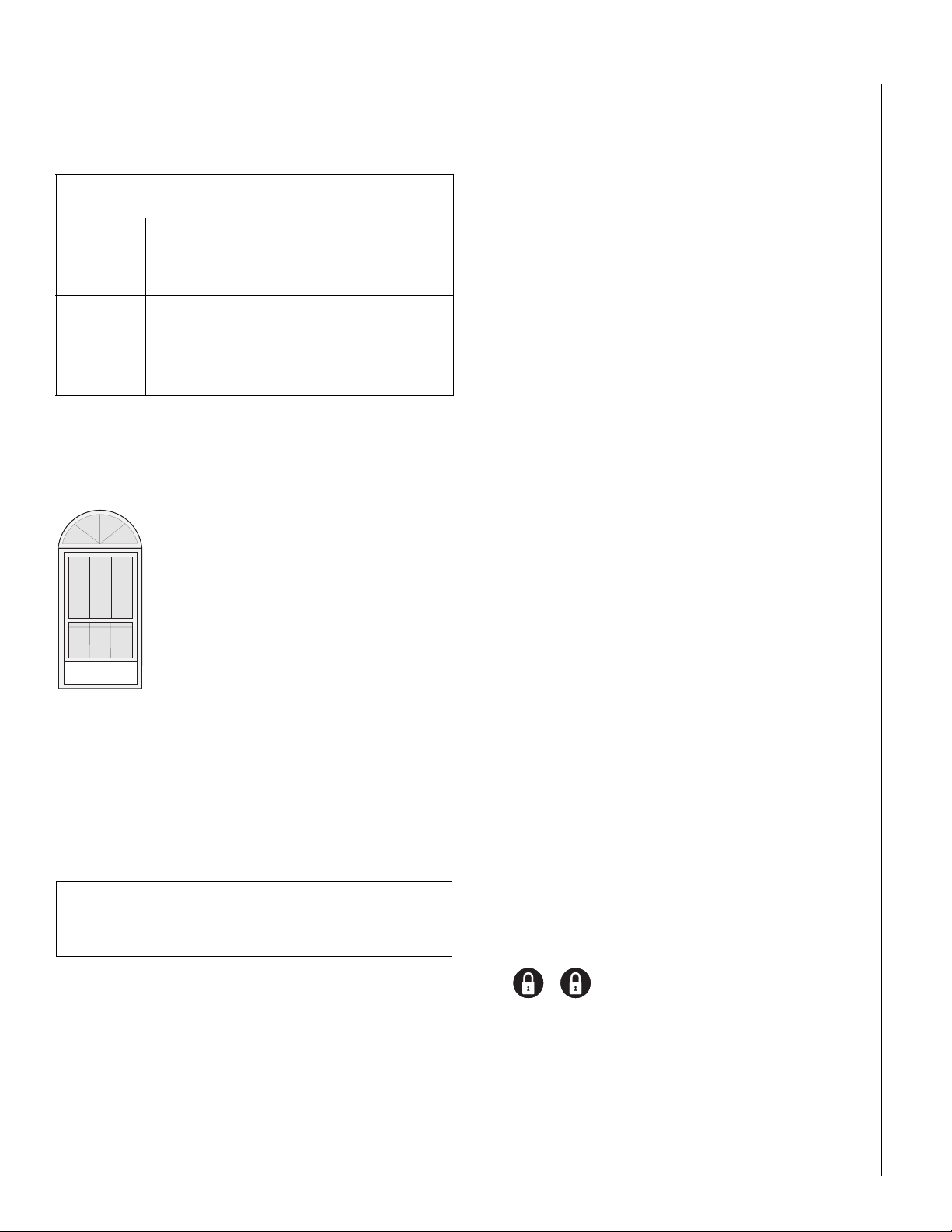
The first touchpad is called a fixed English touchpad.
It communicates by using lighted text and an 11-character display.
The second touchpad is called an alphanumeric touchpad and
communicates by displaying text on a two-line display.
A se n so r is a c tiv a te d .
The senso r alerts the
panel immediately.
COMMUNICATING WITH THE PANEL
Your system can be set up to communicate with you through:
• S tatus beeps
• Alarm sirens
• Touchpad text
• Pager information
The pan el activates sirens. If the
sy ste m is m o n ito re d , th e p a n e l
calls the central m onitoring station.
T h is d ecisio n is b ase d o n system
program m ing and the current
a rm in g le v e l.
The central m onitoring station
operator reports the alarm to
the police or fire departm ent.
Page 4

4
Instructing the Panel
Not just anyone can walk up to a touchpad and operate your security system. Before the syst em will process most commands, users
are required to enter a pre-programmed 4-digit access code.
Access codes are discussed in detail on page 10.
Command A ccess C od e
Keychain touchpads that are enrolled as part of the system do not
require an access code, but are usually kept in an individual’s
pocket or purse.
If you would rather use an actual key to arm and
disarm the system, your security dealer can install a
special key and keyswitch in your home.
How Your System Communicates with You
Touchpads and i nterio r siren s produc e a v ariety of operating beeps
to inform you of different system states and operations.
Key Beeps
A Key beep is the tone y o u hear whe n you press a button on a
touchpad. The sound confirms that the button was pressed adequately. Key beeps can be turned on or off by the installer.
Status Beeps
Status beeps from touchpads or sirens sound when there is a
change in the current status of the system. Status beeps are not
alarms, but they do warrant your attention.
There is more than one type of Status beep:
• Exit Delay beeps indicate that an arming command has been
entered and the countdown to arming has begun.
• Entry Delay beeps indicate that you’ve entered the building and
the countdown to an alarm has begu n. (So disarm the sy st em as
soon as you get in!)
• Trouble beeps tell you that there is a problem with the sys t em o r
one of its components.
• Chime feature beeps tell you that a door was opened.
• Protest beeps inform you that you’re trying to arm the system
while there is an open door or window.
• Sensor test beeps are the sound the system makes during a sensor test to indicate that a sensor was tested properly.
Status beeps are described in more detai l thr oug ho ut the manual.
Pager Notification
Your system can dial the phone numbers of three different pagers
to notify pagerholders of events they ma y want to be awar e of .
Some of the events include:
• when the system is disarmed,
• when the system is armed,
• trouble conditions in the system, and
• alarm conditions.
For more information, see “Notification by Pager” on page 12.
What Happens When There is an Alarm
In the event of an alarm, several things happen at once:
• Sirens and hardwired touchpads emit emergency tones
• Panel notifies the central station for help.*
• Message appears on fixed English or alphanumeric touchpads.
* Your system may or may not be monitored.
If it is not monitored, no call will be made.
ARMING YOUR SYSTEM
Since your se curity needs may vary throughout the da y, the system
was designed with thr ee armin g le vels. By arming your sy stem to a
particular level, only those sensors pr ogrammed to detect in that
arming level will report alarms.
Level 1—OFF
Use Level 1 when intrusio n detection is not necessary. For example, on an active Saturday morning—kids playing inside and out;
someone working in the garage; various house projects going on.
Even though Level 1 disarms the system, your system continues to
monitor for fire, smoke, carbon monoxide, and/or panic alarms if
your system has these devices installed.
Here are some other situations in which you’d set the system to
Level 1—OFF:
• Upo n ent ering yo ur armed home or business . Wh en ent erin g the
armed premises throug h a designated dela y door , the entry delay
time begins. Entry Delay beeps r emind you to disarm the system.
• Before opening a door or window while inside or outside the
armed home or business. When you wake up in the morning and
want to get your newspaper, you must disarm the system before
opening the door to prevent an accidental alarm.
FIRE AND SMOKE ALARMS
If your syst em contains smoke and fire sensors, it monitors the
premises for smoke and fire alarms 24 hours a day and in all arming levels.
These alarms cannot be cancelled or aborted and are always
reported to the central station. Since many communities charge
for dispatching the fire department in error , your dealer may give
you specific instructions to follow in the event of an accidental
smoke or fire alarm. Recor d these in s tructions in the Appendix A
User Sheets under “Accidental Smoke and Fire Alarms.”
Clearing Smoke Sensors
Once a smoke sensor has been in alarm, it is considered “Open” or in “Trouble” until it is reset:
•Press 1 + Code, once to silence the alarm.
•Press 1 + Code, twice to reset the smoke alarm.
Page 5
5
In Le v e l 2 S T A Y , sim ply p re ss
before opening the door.
The door m ust be closed again
w ithin 2 m inutes to avoid alarm .
C ontact yo ur dealer if you 'd
lik e to u s e th is fe a tu re .
D
D
(See the section on “Preventing Accidental Alarms” on page 6 if
you would like to be able to leave quickly when the system is
armed.)
• To stop sirens and cancel an alarm. When an alarm condition
occurs, disarming the system turns off any sirens.
To disarm to Level 1—OFF using a touchpad:
1. Press 1. Touchpads display “Enter Code.”
2. Enter your access code.
Touchpads display date and time or programmed text.
3. The system sounds one long beep.
Arming Level 2—STAY
There are times when y o u want intrusion protection, bu t s till want
the freedom to move around wi thin your house without setting off
an alarm. For example, in the evening when your family is inside
for the night. In this and similar situations, arm your system to
2—STAY.
KEYCHAIN TOUCHPAD ARMING
To disarm your system with a keychain
touchpad, press the Un lock button.
Your installer can set up your keychain
touchpad to arm the system in one of two ways:
1. Press the Lock butt on to arm the system directly to Le vel 3
with no Exit delay. Using this method, you would not be
able to arm to Level 2.
2. Press the Lock button to increase the arming level each
time it is pressed (Lev el 1 to Le v el 2, or Le v el 2 t o L ev e l 3).
The Exit delay time would be applied.
QUICK ARM
Y o ur sy stem may be set up so that you’r e able to arm the
system without using an access code.
To use Quick Arm:
• Increase the arming level by simply pressing 2 or 3
at any touchpad.
Decreasing the arming le vel requires that the user enter a code.
Stay
2
S im p ly p r e ss o r
to in c re a se th e a rm in g le v e l.
To decrease the arm ing
le v e l, y o u 'll n e e d t o e n te r
an access code.
C ontact yo ur dealer if you 'd
lik e to u s e th is fe a tu re .
Away
3
23
To arm to Level 2—STAY using a touchpad:
1. Close all protected perimeter doors and windows.
2. Press 2 a t any t ouchpad. Touchpads display, “Enter Code.”
3. Ent er y o ur acc ess code. Touchpads display,
”Armed to STAY.”
4. The system sounds two short beeps.
5. If lea ving the prem ises, exit through a designated dela y door
immediately .
Arming Level 3—AWAY
At other times, y ou w ant e v ery sensor t o be alert: When the family
is away from home, or, in a business, after closing time.
In this and similar situations, set your system to 3—AWAY for maximum protection. All sensors are active—perimeter door and window sensors, and interior motion detectors.
To arm to Level 3—AWAY using a touchpad:
1. Close all perimeter doors and windows.
2. Press 3 a t any t ouchpad. Touchpads display, “Enter Code.”
3. Ent er y o ur acc ess code. Touchpads display,
”Armed to AWAY.”
4. The system sounds three short beeps.
5. Exit through a designated delay door immediately.
QUICK EXIT
Note: In UL Listed systems, this feature is disabled.
Y our syst em may be set up so that when y our syst em is armed
to Level 2—STAY, you’re able to press D on any touchpad
and simply walk out of the door without ha ving t o disarm and
rearm the system.
This is useful when your system is armed and you wa n t to
quickly pop outside to pick up the newspaper without disarming your system.
IMPORTANT: If you step outsi de and are plan ning to come
back in, do not close the door behind you!
To use Quick Exit:
1. When the system is armed to 2—STAY, press D at any
touchpad. Opening the door without pressing D
will cause an alarm.
2. Open the door and go outside.
Leave the door open if you are planning to come back in!
3. Come back in within two minutes and close the door .
The system will rearm to 2—STAY.
Page 6

6
USING THE CHIME FEATURE
Turn ing on the Chi me featur e is lik e ha ving bells o n ev ery prot ected
door and window. When this feature is on, sirens and speakers
sound 2 beeps whenever anyone opens a protected door or window.
The Chime feature works only in Level 1—OFF.
To turn Chime on/off:
• While in Level 1—OFF, from any touchpad, press 7 + 1.
While the Chime feature is on, touchpads display,
“CHIME ON” or “CHIME IS OFF.”
When the system is armed again, Chime becomes deactivated.
Chime-On-Close
The Chime-On-Close feature works like the regular Chime feature,
but in addition to the double beeps heard upon opening a protected door or window, the system sounds one long beep when
the door or window is closed again.
You can turn the Chime-On-Close feature on or off from the programming menu. Refer to Appendix C, “Programming Menus” for
information on programm in g your system.
PREVENTING ACCIDENTAL ALARMS
Y o ur secur ity system is enginee red with advanced technology that
reduces the chance of an accidental alarm caused by a technical
problem. In wireless systems, this technology prevents other
devices, such as garage door openers, ham radios, television
remote control s, and cellul ar ph on es, from interfering with yo ur
security system.
Most accidental alarms occur when le aving the house after arming
the system, or upon returning, before disarming the system.
If, for example, you ar m the syst em, then run ups tairs for something
you forgot, the Exit Dela y time may expire. Once the Exit Delay
expires, opening an armed do or or moving in front of a mo tion
detector will cause an alarm.
Guidelines for Preventing Accidental Alarms
Following these guidelin es wil l g o a long way toward preventing accidental alarms.
✓ Close doors and windows before you leave your
house.
✓ When getting ready to leave the house, gather the
things you w ant t o tak e with you so you can e xit imme diately after arming the system.
✓ Always enter and exit within the programmed delay
times.
✓ Make sure you leave through a door that has a delay
time set for it. If you arm your system, then leave
through a door without a delay time, an alarm will
immediately sound.
✓ When you return, immediately disarm your system.
✓ Be aware of the devices in your security system and
learn how each one operates.
✓ Listen t o sy stem beeps. Take note of any t ou chpad
messages which indicate the sys tem’s current status.
✓ If you ha ve pets, ask your installer if y o u need pet
lenses in your motion detectors. Pets climb higher
than you may guess, causing alarms when you are
away.
✓ Check the location of your smoke detectors. Smoke
detectors near bathrooms can be tripped by steam
from a shower. Smoke detectors near the kitchen can
be tripped by cooking smoke.
Refer to the User Sheet in Appendix A to determine what
the specific settings are for your system.
Aborting Accidental Alarms
Y o ur sy stem can be set up with the opportunity to abort an accidental intrusion, Police or Auxiliary alarm. (Fire alarms caused by
smoke sensors, fire panic alarms, and heat sensors cannot be
aborted.)
If the Dialer Abort feature is turned on, disarming the system (thus
aborting the alarm), within a specified time period will silence the
siren and prevent the alarm from being reported to the central
monitoring stat ion.
Aborting a fire alarm will silence the siren, however fire alarms are
always r eported. If an accidental fire alarm has sounded, follo w the
procedures of your central monitoring station to prevent a false dispatch.
To cancel an alarm:
• Press 1 + Code.
Page 7

7
A
y
s
y
EXIT AND ENTRY DELAY TIMES
After arming your system, you need time to exit the
building so you w on’t set off an alarm. Lik ewise , upon
returning to your home or business, you’ll need
enough time to open the door and get to a touchpad
to disarm the system.
•The Exit Delay is a period of t i me long enough to let you le ave
through a designated delay door after arming the system.
•The Entry Delay is a period of time long enough to let y ou unlock
a designated delay door and get to a t ouchpad to disarm the system.
Exit Delay Example
Y o u’re about to go on an errand. You are inside your house and
have just armed the system to Level 3—A WAY.
The interior sirens and touchpads sound three quick status beeps,
telling you that the system accepted the command and has started
the Exit Delay time.
During the Exit Delay time, the system sounds one short beep
every 4 seconds. Exit the premises immediately.
During the last 10 seconds of the Exit Delay, you’ll hear a three
more quick status beeps. These beeps indicate that the Exit Delay
has ended. Opening an armed door or windo w after the Exit Dela y
has expired will cause an alarm.
B E E P S
fte r a rm in g ,
o u 'll h e a r
3 quick
ta tu s b e e p s .
During the Exit Delay,
you'll hear one b eep every
fo u r s e c o n d s .
Leave th e prem ises n ow .
3 quick status
b e e ps so u n d
b e fo re th e sy stem
is a r m e d .
Extended Delay
In some situations, additional time is needed t o arm or
disarm the system from, for example, a protected outside gate or door. In these instances, the installer can
program an extended delay, giving as much as 16
minutes to exit or disarm the system befor e setting off
an alarm.
Refer to the Appendix A User Sheets, “Delay Doors and Delay
Time Settings,” for a list of actual exit delay times.
Exit Extension
Note: In UL Listed systems, this feature is disabled.
Y our sy s t em may be set up so that the delay time is restart ed if you
re-open the delay door during the initial delay time.
This is useful if, after arming the sy st em, you w alk out the doo r, the n
remember something you forgot inside. You can re-enter and exit
through the delay door without disarming and re-arming the system.
Note: The Exit Extension will work on the first re-entry only.
If your syste m is not usin g this feature, you must disarm the sys tem
when you re-ent er the armed pr emises to av oid setting off an alarm.
No Delay—For Instant Alarm
Y ou can choose to turn off the Entry and Exit Delays,
causing the delay doors to arm immediately. Anyone
entering the house thr ou gh the de lay door when the
system is set to No Delay would immediately cause an
alarm.
No Delay is normally used:
Entry Delay Example
Y o u ar e returning to your house that is armed t o Level 3—AWAY.
When you unl ock an d en t e r the de sig nat ed del a y do or, the interior
sirens and touchpads sound tw o short beeps e very two seconds.
This tells you that the Entry Delay time has begun and r eminds you
to disarm the system t o a void setting off an alarm.
During the last 10 seconds of Entry Delay, you’ll hear one beep
every second.
Y our i ns talle r wil l work with you t o deci de which doo r(s) sho uld be
delay door(s), and deter mine the dela y times that will w ork bes t f or
you and your family. Then, the insta ller will program the Exit and
Entry Delay times into your system.
• When you’re staying at home, after you’ve armed the system.
• When you’re arming and disarming your house from the outside.
(You must have a wireless touchpad in order to do this.)
Arming to Level 2 or 3 with No Delay:
1. Close all perimeter doors and windows.
2. Exit the premises if arming to Level 3—AWAY.
3. Ent er: 2 + Code or 3 + Code.
The system sounds two or three short beeps.
4. Immedi ately after hearing the beeps, press 4 for No Delay.
Touchpads display, “Armed to STAY No Delay” or “ARMED
TO AWAY NO DELAY ,” f o r exampl e.
Changing the arming level will restore delay doors to their normal
Exit and Entry Delay times.
B E E P S
U pon entering, during the
Entry D elay, yo u'll hear 2 b eeps
2 se co nd s.
ever
D isarm th e sy stem be fo re
the last o f 1 0 qu ick statu s b ee ps
to avoid an acciden tal alarm .
Page 8
8
Auto STAY Arming Feature
The Auto STAY Arming feature helps cut down on false alarms in
the event that you arm the syst em to 3—AWAY , but fai l to leave
during the exit delay time. Here’s how it works:
If you arm the system to Level 3—AWAY,
and do not leave the premises within the exit delay time—
The system can tell that no one opened and
If feature
turned on
If feature
turned off
Y o ur de aler can turn this feature on or off for you.
closed a delay door within the delay time. It
assumes that someone is still inside and the
panel will arm to 2—STAY to avoid a false alarm.
The system arms to Level 3—AWAY regardless of
whether or not a delay door has been opene d
and closed.
Your movement inside the premises could activate a motion detector, causing an alarm.
ARMING WHILE A DOOR OR WINDOW IS OPEN
It is possible to arm your system while leaving a
door or window open. This is useful if, f or example, you like to sleep at night with the window
open.
If the door or window has a sensor ins tall ed on it,
the system must be told to ignore, or bypass, that
sensor when it’s open. All other sensors will
remain active .
There are two methods for bypassing a sensor:
• Directly — After arming the system, bypass door/window sen sors
before you open them. Y ou must kno w the sensor number of the
door or window you wish to bypass. To bypass directly, the user
code must have been given the Direct Bypassing attribute. (See
“Assi gn ing the Dir ec t Bypassing Attribute” on page 10.)
• Indirectly — As you are arming, by pass senso rs on alr eady-o pen
doors and window. This method should not be used in UL-list ed
installations.
REMEMBER:
When a sensor is bypassed, you are allowing that door or
window to be unprotected.
Bypassing a Sensor Directly
Use this method if the system is arme d and you would like to open
a window without disarming.
Refer to the Appendix A User Sheets to determine what the sensor
number is for the sensor you wish to b ypass.
To bypass sensors directly:
1. Close all doors and windows.
2. Arm your system to the desired level.
3. A t any touchpad, press ƒ + Code + sensor number.
(ƒ is labeled Bypass)
4. Touchpads display, “Bypassed Zones 01,” or
“SENSOR 01 BYPASSED,” for example.
If the touchpad displays “INVALID,” or if the touchpad
sounds one long beep, make sure that you entered a valid
sensor number. Heat and smoke sensors cannot be
bypassed.
5. Bypass other sensors, if necessary, by repeating Step 3.
6. The b ypassed door or window can now be opened.
To arm bypassed sensors:
• Arm the system again.
Note: You cannot bypass sensors directly using a
keychain touchpad.
Bypassing a Sensor Indirectly
Use this method if you are arming the system and would like to
bypass doors and windows already open.
To bypass sensors indirectly:
1. Leave open only those doors and windows that are to
remain open. Close all others.
2. Arm your system to the desired level. The touchpad emits
protest beeps and displa ys “PR OTEST,” because of the open
sensor(s).
3. At any touchpad. press BYPASS. Touchpads with displays
show, “Bypassed Zones 01,” or “SENSOR 01 BYPASSED,”
for example.
4. The system sounds arming level beeps to indicate that the
system is armed and open sensors have been successfully
bypassed.
To arm bypassed sensors:
• Arm the system again.
To bypass sensors indirectly using a keychain touchpad:
• Press the Lock button once to arm the system and again to
bypass open sensors:
+
Was the Bypass Successful?
To confirm whether or not a sensor was bypassed:
• Press the Status button on the touchpad.
(‚ is labeled Status.)
Touchpads with displays list bypassed sensors or zones.
Page 9
9
CHECKING THE STATUS OF YOUR SYSTEM
Checking the system s tatu s means finding out about the curre nt
condition of your sy stem. This includes finding out if any senso rs
are open or currently bypassed, whe the r or not the AC power and
backup battery are okay, the nature of the most recent alarm, and
more, depending on the features in u se and the equipment in y o ur
system.
Check the system status if:
• Your system sounds trouble beeps (five short beeps every
minute).
• Your touchpads display, “Zone s,” “POLICE,” “AUXILIARY,” and
“FIRE.”
• Your touchpads display, “Press Status” or a blinking ✽.
Short System Status
A Short Status indicates the current arming level, sensor status
(whether open or bypassed), low battery, supervisory, AC power or
backup battery failures.
To get a Short System S tatus:
• Press ‚. (‚ is labeled Status.)
The system sounds beeps according to the current arming
level. (One for Level 1, two for Level 2, three for Level 3.)
Touchpads display the status information, for example:
“System is OK,” or “SENSOR 02 OPEN.”
If an alarm or syst em tr ouble c ondi tion h as occu rr ed, it is displayed
on a touchpad the first time you perform a Short or Full Status
check. Performing a system status check a second time displays
the system status including any trouble conditions.
If any alarm or system trouble is active, it continues to show up in
every status check until the system is disarmed.
System Alarm Sounds
The sirens and touchpads in your system emit alarm sounds whenever an alarm occurs, either b y a senso r or panic butt on activation.
Each type of alarm sounds and reacts differently when activated, as
described in the following table.
Type of Alarm Alarm Sound
Fire
Police
Auxiliary
Repeating series of three beeps
Continuous tone
Rapid beeps
PANIC ALARMS
Panic alarms are easily activ at ed from an y to uchpad to quickly ale rt
the central monitoring station to a Fire, Police, or Auxiliary emergency. A panic alarm can be acti va ted at any ti me, regar dless of the
current arming level: 1—OFF, 2—STAY, or 3—AWAY.
This system is desi gned to in form a cen tral moni toring s tation of the
nature of the emergency so the correct personnel can be dispatched immediately.
Fire Panic
The Fire panic alarm sounds from all interio r and ext e rio r sirens.
On monitored systems, the central monitoring station responds by
calling the fire department.
Full System Status
A Full Status combines the Short Status information with added
details about specific system features.
To get a Full System Status:
• Press ‚ + ‚. Interior sirens sound beeps according to
the current arming level. Touchpads display the status information, for example, “System is OK,” “SENSOR 03
BYPASSED,” “SYSTEM BATTERY IS OK,” “AC POWER IS
OK.”
Note: A Full System Status is not available from the fixed English
touchpad.
To activate a Fire panic alarm from a touchpad:
• Press and hold both Fire buttons for 2 seconds.
Police Panic Alarm
The Police panic alarm sounds from all interior and exterior sirens,
scaring off any intruder and alerting neighbors to the trouble. On
monitored systems, the central monitoring station responds by calling the police.
To activate a Police panic alarm using a touchpad:
• Press and hold the Police button(s) for 2 seconds.
To activate a Police panic alarm from a keychain touchpad*:
• Press and hold the Lock and Unlock buttons at
the same time for 2 seconds.
* The installer must configure the Police panic alarm to
work this way.
Page 10

10
Auxiliary Panic Alarm
The Auxiliary panic alarm sounds from interior sirens only. It is typically set up by your security dealer, based on your specific needs.
On monitored systems, the central station responds by calling the
service or agency you specified through your dealer.
To activate an Auxiliary panic alarm from a touchpad:
• Press and hold the Auxiliary button(s) for 2 seconds.
To send an Auxiliary panic alarm from a keychain t ouchpad :
• Press and hold the Lock and Unlock buttons at
the same time for 2 seconds.
Siren Time-out
If the system is not disarmed after an alarm, the si rens will conti nue
to sound until the time-out period is reached. The time-out period
can be programmed only by your installer or dealer.
Even though reaching the end of the time-out period stops the
sirens, if your sys tem is monitored, the central s tatio n will con sider
the alarm in progress until the sys tem is manually disarmed.
ACCESS CODES
The system r e qu ires a valid access code befor e i t wil l process most
commands. The Appendix A User Sheets provide a location for
you to record the System Master and User codes.
Using the Programming Menus
Some system se tting s can be chan ged b y y o u, the user, while other
settings must be changed by the installer.
To change system settings, you’ll use the System Master code to
enter a series of progr amming menus. Appen dix C giv es a detailed
explanation of how to use the menus or, if desired, how to use pr ogramming shortcuts.
Programming Access Codes
User codes can be given certain attributes which det er min e
whether the user can bypass a sensor or perform system tests.
Changing a User Code
To change or assign a user access code:
1. Enter the programming menus by pressing
9 + System Master Code.
2. Press 10 n n 0 where nn is user 00 through 15.
3. Enter the desired 4-digit code, then ƒ.
4. ‚ + 4 + ƒ to exit the programming menus.
Note: The system will not accept the same code for
two different users.
Erasing a User Code
When a code is deleted from the system, that code no longer acts
as a key for operating the system in any manner.
System Master Code
There is one System Master co de. The Sys tem Maste r code is used
to enter the programming menus for your sy s tem. The default Sys-
tem Master code is 1234. It is important that you change the
default code and record the new code in the Appendix A User
Sheets.
Regular User Codes
There are 16 Regular User codes which act like keys to arm and
disarm the system. If n ecessary, they can be assigned t o neighbors,
baby-sitters, or repair persons for temporary use. Regular user
codes can be changed in the programming menus and are easily
deleted from the system when no longer necessary.
Good User Code Hygiene
To pr eserv e the int egri ty of your syst e m,
keep user codes confidential and
delete extra codes as soon
as they are no longer
needed.
We recommend that you avoid using
obvious code patterns such as 1234 or
1111, 2222, etc.
To erase a user code:
1. Enter the programming menus by pressing
9 + System Master Code.
2. Press 10 n n 0 where nn is user 00 through 15.
3. Enter the System Master code, then ƒ.
4. ‚ + 4 + ƒ to exit the programming menus.
Assigning the Direct Bypassing Attribute
Direct Bypassing is a user code attribute that allows the user to
bypass open sensors. If the user code does not have this attribute
turned on, the user will not be able to bypass sensors directl y.
To assign Direct Bypassing to a user:
1. Enter the programming menus by pressing
9 + System Master Code.
2. Press 10 n n 1 where nn is user 00 through 15.
3. To turn Direct Bypassing:
• on, press 2 + ƒ.
•off, press 1 + ƒ.
4. ‚ + 4 + ƒ to exit the programming menus.
Page 11

11
m
m
m
m
m
m
Assigning the System Test Attribute
System Tests is a user code attribute that allo ws the user to perfo rm
system tests. If the user code does not have this attribute turned
on, the user will not be able to perform phone or sensor t e sts.
To assign the System Testing to a user:
1. Enter the programming menus by pressing
9 + System Master Code.
2. Press 10 n n 2 where nn is user 00 through 15.
3. To turn System Testing:
• on, press 2 + ƒ.
• off, press 1 + ƒ.
4. ‚ + 4 + ƒ to exit the programming menus.
The Touchpad Tamper Feature
The installer can program your system to send a Police
alarm in the case of possible touchpad tampering.
If more than 40 key s are pressed wh en the syst em asks for
a code, and those keys trok es are not part of a valid access
code, a siren will sound.
ADJUSTING SYSTEM SOUNDS AND
OUCHPAD BRIGHTNESS
T
Arming Your System Silently
Use the Silent Arming feature to arm your system without disturbing people throughout the house with arming status beeps. There
are two methods for implementing Silent Arming:
• Silent on Demand (User presses 5 before arming.)
• A rming Always Silent (Silent Arming feature on).
Regardless of the method employed, when Silent Arming is in
effect, no Exit beeps sound.
Note: Protest beeps will always sound when bypassing a sensor.
Silent Arming on Demand
Pressing 5 before arming silences arming status beeps from
touchpads and interior siren s.
To use Silent Arming on demand:
1. From any touchpad, press 5.
2. Within 4 seconds enter: 2 + Code or 3 + Code.
SETTING THE TIME AND DATE
Although the installer usually sets the time and dat e at the time of
installation, the user can change it when necessary. See Appendix
C, “Programming Your System” for more detailed information on
setting this feature.
To set the system time:
1. Enter the programming menus by pressing
9 + System Master Code.
2. Press 00.
3. Enter the correct time in 24-hour format (4 digits),
then press ƒ.
For example, if the current time is 7:23 a.m.,
press 0723 + ƒ.
4. Press ‚ + 4 + ƒ to exit the programming menus.
24-H our Form at
00:00
01:00
02:00
03:00
04:00
05:00
=
Midnight
=
1:00 am
=
2:00 am
=
3:00 am
=
4:00 am
=
5:00 am
06:00
07:00
08:00
09:00
10:00
11:00
=
=
=
=
10:00 am
=
11:00 am
=
6:00 am
7:00 am
8:00 am
9:00 am
12:00
13:00
14:00
15:00
16:00
17:00
=
=
=
=
=
=
Noon
1:00 pm
2:00 pm
3:00 pm
4:00 pm
5:00 pm
18:00
19:00
20:00
21:00
22:00
23:59
=
=
=
=
=
=
6:00 p
7:00 p
8:00 p
9:00 p
10:00 p
11:59 p
Arming Always Silent
Turning this feature on in the programming menu means that the
status beeps that come from to uchpads and int erio r speak er s whil e
arming will always be silent. You wi ll not have to enter 5 before
arming, as with Silent Arming on Demand.
See Appendix C, “Programm ing Your System” for more detailed
information on setting this feature.
To enable Silent Arming:
1. Enter the programming menus by pressing
9 + System Master Code.
2. Press 2 + 1.
3. To turn Silent Arming:
• on, press 2 + ƒ. No system status beeps will sound
while arming.
• off, press 1 + ƒ. System status beeps will sound from
touchpad while arming.
4. Press ‚ + 4 + ƒ to exit the pr ogramming menus.
To set the system date:
1. Enter the programming menus by pressing
9 + System Master Code.
2. Press 01.
3. Enter the current date as 6 digits (mm/dd/yy) then press ƒ.
4. Press ‚ + 4 + ƒ to exit the programming menus.
Page 12

12
Adjusting the Touchpad Beeps
The frequency or pitch of chime and trouble beeps from e ach fixed
English touchpad can be adjusted individually to a more desirable
or distinct tone.
Chime and trouble beep tones so un d using the default frequency
during, or within 15 seconds of any button activity at that specific
touchpad.
To change status tone pitch:
1. Press and hold the ‚ and 0 until you hear a steady tone,
then release the buttons.
2. Press an d hold 1 to low er the pitch or press and hold 2 to
raise the pitch.
3. Release the button when the desired pitch is heard.
After about 15 seconds of no touchpad activity, the steady tone
stops sounding.
Adjusting the Touchpad Display Brightness
You may want to change the brightness of a touchpad display
based on its location in a building or room. For example, dim the
touchpad display in a bedroom or enhance a display near a window.
Changing the touchpad display affects only the touch pad curr ently
being used.
To change touchpad display brightness:
1. Enter the programming menus by pressing
9 + System Master Code.
2. Press 2 + 2.
3. Select a br ig htne ss level:
• 0 + ƒ Off
• 1 + ƒ Low
• 2 + ƒ Medium
• 3 + ƒ High
4. Press ‚ + 4 + ƒ to exit the programming menus.
After dimming the display , pr essing any butt on momentarily r eturns
the display to full brightness. After 15 seconds without touchpad
activity, the display returns to the set dimmed leve l. If an alarm
occurs while the display is dimmed, it automatically returns to the
full brightness level and stays that way until you disarm your sy st em .
NOTIFICATION BY PAGER
Your system can notify up to three different pager phone numbers
to report syste m e vents. The installer can progr am an y pager to
receive pages for one or more of the following groups:
• High Level Reports,
which includes the foll owing reports:
– Sensor alarms – Bus failures
– Sensor Tampe r – No activi ty alarm
– Sensor Restorals – Fire panic
– Phone test – Police panic
– Receiver failure – Auxiliary panic
– Receiver jam – Duress alarm
– Touchpad tamper
• L ow Level Repo rts,
which includes the foll owing reports:
– Bypass sensors – AC power fail
– Low battery – CPU low battery
– Sensor Supervisory – Auto phone t es t
– Trou ble – CPU back in service
– Phone test – Phone Failure
– Touchpad supervisory – Event buffer full
– Touchpad low battery – Force armed
– Force armed (repo rts when a user bypasses
sensors while arming system)
• Opening and Closing reports
• Latchkey Paging
Pager Me ssages
When an event is reported on a numeric pager, the following information is included:
Event code L a st fo u r d ig its o f c e n tra l
station account num ber
Sensor num ber or user num ber
Although all three types of information can be reported on your
pager, y our pag er service determines ho w the inform ation will actually appear.
Page 13

13
r
Event Code in Page
This part of the page let’s you know what has happened.
Table 1. Event Codes in Pages
Code Indicates
009
1 1 1
1 1 8
1 1 9
222
333
555
888
999
A sensor has been restored to its non-alarm state
System has been disarmed
System trouble has been fixed
System alarm condition has been cancelled
System armed to Level 2
System armed to Level 3
System phone test
System has a trouble condition
System is in alarm condition
Sensor Number or User Number in Page
This part of the page let’s you know who or what is causing the
event.
Table 2. Sensor Numbers or User Codes in Pages
Code Indicates
000
001 — 024
600 — 615
678
679
System event not caused by a sensor or user
Sensor numbers 1 through 24
User codes 00 through 15 used
System Master code used
Installer code used
your provi der t o see exactly ho w y our accoun t number will appe ar
on your pager.
Streamlining the Page
If you feel that it is not necessary to see y our acco unt nu mber with
each page from your sy s tem, you may elect t o have the Streamlining feature turned on. Your page will contain only an event code
(Table 1) and a sensor or user number (Table 2).
Ask your dealer or installer if you would lik e the Streamline feature
turned on.
Sample pager message with the
Streamline feature turned on:
Event code
Sensor num ber or user num be
OPENING AND CLOSING REPORTS
The Opening and Closing Reports feature allows up to three pagerholders and/or the central station to be notified whenever the system is armed and/or disarmed. R efer to the Appendix A User
Sheets to see which pagers have been set up to receive a page for
this feature.
The Opening and Closing Reports feature can be enabled only by
the installer .
If the feature is on, pagerholders will rece ive:
• an Opening Report page every time the system is disarmed:
111 for Level 1—OFF, and the user code entered.
• a Closing Report page every time a user arms the system:
222 for Level 2 or 333 for Level 3, and the user code entered.
See “Notification by Pager” on page 12 for more information on
paging reports.
680
697
698
699
Dealer code used
Quick Arm used
Keyswitch sensor used
System armed i tself because it is being serviced
or powered-up
Account Number in Page
This part of the page let’s you know where the event is occurring.
Table 3. Account Number
Code Indicates
XXXX
Some pager providers transmit only numbers and not alpha-characters. If your account n umber cont ains alpha- charact er s, check with
4-digits of account number
Page 14

14
LATCHKEY PAGING
The Latchkey paging feature allows up to three pagerholders to be
notified when the system is disarme d. Latchke y pages do not re port
to the central s tation. This f eature is usef ul when y ou’re at wor k and
would like to be notified when your daughter or son arrives home
and disarms the system.
The Latchkey paging feature can be enabled only by the installer.
Refer to the Appendix A User Sheets to see which pagers have
been set up to receive a Latchkey page.
Only Latchkey-design ated user code s can cause a Latchk ey page to
be sent. By default, this includes the first 5 Regular User codes. If
you’d like more user codes to be included, contact your installer.
Preparing the system to send a Latchkey page:
• Arm the syste m, then ent er 6. Touchpads display briefly:
“Pager on,” or “LATCHKEY PAGER ON.”
To send a Latchkey page:
• Latchkey-designated user disarms the system.
Pagerholders wi ll rec eiv e a messag e containing 111 and the
user code entered to disarm the system.
Note: If you have the Openi ng and Closing Reports feature turned
on, you’ll receive a page every time someone disarms the
feature, not just Latchkey-designated user codes.
NO ACTIVITY FEATURE
The system can monitor the activity in your home and automatically call for help if normal activities are not detected within a
defined period of time.
Note: This feature is not active in Level 3—AWAY.
For example, if someone falls and can’t move, the system will
detect that normal activities, such as opening doo rs and windows,
have not occurred for a predetermined No Activity time.
The system sounds an auxiliary alarm to le t y ou kno w ther e ma y be
a problem. If all is well, you can stop the siren by disarming your
system. If no one disar ms the sy stem for 5 minutes, your system
calls the central monitoring station. The central monitoring station
will send emerg ency personnel t o the pr emise s to check out the situation.
Refer to the Appendix A User Sh eets t o see if the No A ctivity feature is currently a vail able to y ou and the duration of the No A ctivity
setting. If the feature is no t currently av aila ble t o you, contact your
installer.
USING THE PANEL DOWNLOAD FEATURE
To download to the panel is t o repl ace the old inf ormation in it with
new information. Do wn lo ading is performed only by yo ur dealer
using ITI software specifically designed for this panel.
Turning the Download feature on allows the dealer remote access
to your panel in or de r t o :
• Updat e your account.
• Back up data from your panel.
• Allow your dealer to quickly implement requested programming
changes.
Note: Before allowing an y download sessions, the system must be
disarmed to level 1-OFF.
To enable/disable the Panel Download setting:
1. Enter the programming menus by pressing
9 + System Master Code.
2. Press 2 + 0.
3. To turn Downloading:
• on, press 2 + ƒ . The dealer wil l be able to access y our
system remotely if necessary.
• off, press 1+ ƒ. The dealer will not be able t o access
your system remotely.
4. Press ‚ + 4 + ƒ to exit the programmi ng menus.
SYSTEM INFORMATION
There is information about your sy stem that is useful t o know. This
includes the factory code, the syst em numbe r, and the system level.
After identifying the information for your sy stem, make a not e of it
in the Appendix A User Sheets.
To identify system information:
1. Enter the programming menus by pressing
9 + System Master Code.
2. Press B until the touchpad displays
“System ID,” or “SYSTEM VERSION,” then press ƒ.
• The fi rst information displayed is the factory code.
For example, “FACTORY CODE nnn * nnnn,” or
“F nnn – nnnn.”
• Press B to display the system number. For example,
“N – nnnnnnn,” or “SYSTEM NUMBER ✽ nnnnnnn.”
• Press B to display the system lev el. For example,
“L nnnn,” or “SYSTEM LEVEL nnnn.”
3. Press ‚ + 4 + ƒ to exit the pr ogramming menus.
Page 15

15
TESTING THE SYSTEM
The system cont ains a test mode that allows y ou t o tes t sensors and
panic signals without creating f alse alarms. T es t you r syste m weekly ,
by followin g the instructions in this section careful ly.
Automatic Test Features
Y our se curity system con ducts ro uti ne t es ts, che cking f o r pr oble ms
like pow e r f ail ures, low batteries, sensors tha t ar e n’t working, and
communication trouble with the central monitoring station.
When your sy s t em det ec ts a problem, trouble beeps sound to alert
you. See “Troubleshooting” on page16 for an explanation of the
causes of trouble beeps and what you can do to fix the problem.
Table 3. Sensor Test Procedure
1. Enter Test Mode by pressing
8 + Code + 3.
2. Follow the test procedure for each device.
Touch pads display, “Press S tatus. Sy stem Armed to Sensor Test,” or
“✽✽SENSOR TEST nn MINUTES LEFT.”
When less than 5 minutes remain to the T es t Mode time, the sys tem sounds a sho rt beep
every 60 seconds.
Manual Tests
The automatic tests your system performs provide continuing reassurance that it is working properly. There are also weekly system
tests you can do y oursel f as an added safeg uard. Taking time to do
these tests will familiarize you with your system and alert you to
anything unusual, such as cut phone lines or sensors that have
been tampered with.
Sensor Test
This test verifies that the sensors in your system are operating correctly.
The ability to conduct a sensor test is a code attribute given per
User code. Check the Appendix A User Sheets to see whi ch
access codes have the ability to conduct a sensor test.
Device Test procedure Touchpad Result
Touchpads Send a: Police panic alarm,
Fire panic alarm, and
Auxiliary panic alarm.
Wireless Touchpads Press the Bypass key. Zones nn OK
Keychain Touchpads Press and hold the two assigned panic buttons simultaneously
for 3 seconds.
Panic buttons Press and hold the appropriate panic button(s) for 3 full sec-
onds.
Door/window
sensor
Smoke detector Press and hold the test button until the system sounds transmis-
Open the secured door or window. Zones nn OK
sion beeps.
Touchpad Panic POLICE OK
Touchpad P an ic FIRE OK
Touchpad Panic AUXILIARY OK
POLICE PANIC OK
FIRE PA NIC OK
AUXILIARY PANIC OK
Touchpad nn OK
Touchpad Panic POLICE OK
Touchpad Panic AUXILIARY OK
POLICE PANIC OK
AUXILIARY PANIC OK
Zones nn OK
SENSOR nn OK
SENSOR nn OK
Zones nn OK
SENSOR nn OK
Motion
detector
Rate-of-Rise Heat
Detector
(Not UL investigated)
Shock sensor
(Not UL investigated)
Avoid the motion de tector’s view for 5 minutes, then enter its
view.
Rub your hands together until warm, then place one hand on
the detector for 30 seconds.
Tap the glass twice, away from the sensor. Wait at least 30 seconds before testing again.
Zones nn OK
SENSOR nn OK
Zones nn OK
SENSOR nn OK
Zones nn OK
SENSOR nn OK
Page 16

16
Device Test procedure Touchpad Result
Glass guard sensor
(Not UL investigated)
Freeze sensor
(Not UL investigated)
• I f you need more time to complete testing, restart the timer by pressing 8 + Code + 3.
• Check to see that all sensors have been tested by pressing ‚. Touchpads display a list of untested sensors.
• You will know that you have finished testing when touchpads display, “SENSOR TEST OK” or “ZONES ALL TESTED.”
3. Disarm to Level 1 to exit Test Mode.
Phone Communication Test
The purpose of this weekly t est is to verify that the connection
between the central monitoring station and your sys tem is working
properly.
Most phone tests take only a few minutes, however, your system
will try for up to 15 minutes to establish a connection.
After the test has started, the arming level can be changed to
Level 2—Stay or Level 3—AWAY.
To perform a phone communication test:
1. Contact the central mon itoring station to inform them that
you want to t e s t the phone com mun ication of your syste m.
2. Disarm the system.
3. Press 8 + System Master Code + 2. The touchpad displays,
“System Armed to PHONE TEST,” or “✽PHONE TEST.”
On fixed English touchpads:
After the phone test is complete, the t ouchpad displays
“PHONE TEST OK.” Press ‚.
• If the phone test is successful, the touchpad displays
“System Phone Test Alarm Memory” or “Phone Test
Memory” briefly, then returns t o a normal t e xt di splay.
Press ‚ a second time and the touchpad display s
“System is OK.”
• If the phone test is unsuccessful, the touchpad displays
“Memory Tes t Pho ne ” briefly, then “Alarm Memory
Phone Failure.”
On alphanumeric touchpads:
• If the phone test is successful, the touchpad display
returns to a normal text display.
• If the phone test is unsuccessful, the touchpad displays
“SYSTEM PHONE TEST ALARM,” then, “MEMORY,” and
finally, “PHONE FAILURE ALARM MEMORY.”
If a phone test is unsuccessful, check to see if you hear a dial tone
from phones in the house. Call your dealer if you hear a dial tone,
but your phone test is unsuccessful.
Testing Sirens
The purpose of this weekly tes t is to verify that the panel is activating sirens with the appropriate warning sounds.
Tap the glass 3 or 4 inches from the sensor. Zones nn OK
SENSOR nn OK
Apply an ice cube wrapped in plastic to the senso r.
Do not allow the sensor to get wet.
To perform an alarm siren warning sound test:
1. Contact the central monitoring station to inform them that
you will be activating alarms and they should not dispatch
authorities.
2. Activate alarms of each type (fire, police, auxiliary), one at a
time.
3. Listen for the appropriate siren sound when each alarm is
activated (see “Alarm Sound” table on page 9).
4. Contact the central monitoring station to inform them that
you are finished activating alarms.
Zones nn OK
SENSOR nn OK
TROUBLESHOOTING
Your security system uses a variety of different alarm sirens, status
beeps, and trouble beeps to communicate with you. The next few
pages describe the different sounds and what they mean. Try to
familiarize your self with the differe nces. You will hear some sounds
each time you tell y our security system t o do something, lik e arm or
disarm. Some sounds you will hear on ly when there is a problem
with the system, like a low battery. Other sounds you will only hear
in an emergency. Getting to know your system sounds allows you
to react quickly and appropriately.
Trouble Beeps and Trouble Messages
Tr oubl e be eps are a series of five short beeps, once a minut e.
When your sys tem det ects a pr oblem, it lets y ou kn ow b y soundin g
trouble beeps from touchpads and sirens, an d by tr ouble me ssage s
on touchpad displays.
Table 4 lis ts the causes of trouble beeps, the visu al display you can
expect to see, and possible solutions for the trouble condition.
Silencing Tro ub le Beeps
If possible, correct the situation which is causing the troubl e beeps.
If this is not possible, call for service. If the problem is not corrected, trouble beeps and messages start again 4 t o 10 hours lat er.
To stop trouble beeps:
• Perform a system status check by pressing ‚ on a touchpad,
• change the arming level.
The following table describes the conditions under which trouble
beeps occur and when they begin. (These sounds are heard from
interior sirens and touchpads if available.)
Page 17

17
Q. I can’t arm my system.
A. Try the following:
• If arming to Lev e l 2—STAY or Level 3—AWAY, make sure all monitored perimeter doors and windows are closed.
• Press ‚ for a system status and for clues to the problem.
• Call the installer.
Q. I cannot bypass a senso r: my alphanum e ric touchpad
displays “INVALID” and my fixed English touchpad
sounds a single, long beep.
A. Possible explanations include:
• The sensor you’re trying to bypass may not be active in the current arming level. For example, an interior motion detector will
not be active in Level 2—STAY.
• Some sensors can be bypassed only in certain levels.
For example, motion sensors in Le vel 3—AWAY.
• You may be trying to bypass a 24-hour sensor than cannot be
bypassed, such as a smoke detector.
Q. I can’t arm my system to Level 3—AWAY.
A. If a delay door is open while you’re trying to arm the
system to Level 3, the system will arm to Level 2 instead.
Close the delay door, arm the system to Level 3, then exit
through a delay door.
Table 1. Causes of Trouble Beeps
Touchpad Feedback After
Pressing ‚
AC POWER FAILURE The panel power tr an sf o rmer may be unplugged or there may be an AC power outage. If the trans-
Trouble Condition
former is plugged in, check the circuit breaker or fuse that controls that outlet.
The backup battery will take ov er, but if AC power is not rest ored within 15 minut es, the sys t em will
alert you and the central monitoring station (if your system is monitored). It reports again when
power is restored.
LOW B ATT The power in the emerg e ncy backup battery is low and must be r ec har ged or replaced. If AC
power is out, the security system may shut down once the battery is below the operating level.
When AC pow er is res to red, the panel will r echar ge the batt ery . If the tr ouble co ndition exis ts more
than 24 hours after AC pow er is re stored, call yo ur security dealer for service.
SENSOR SUPERVISORY There is a problem with how the sensor is communicating with the panel.
1. Test the sensor in Test Mode as describe d on pag e pag e15.
2. If the sensor do es no t t e s t OK, call your security dealer for service.
SENSOR TROUBLE A sensor may have an internal problem or a fire/smok e senso r may not have prope rly r eset after
activation, or the sensing chamber may be dirty or partially obstructed.
1. Test the sensor in Test Mode as describe d on pag e pag e15.
2. If testing the sensor does not clear the trouble condition, call your security dealer for service.
SENSOR XX LOW BATTERY A sensor has a low battery.
1. Disarm the sy s tem.
2. Remove the sensor cover. If the battery is an Alkaline AAA, change the battery. If the battery is any other type, call your security dealer for service.
SENSOR XX TAM PER A sensor co ver is off or open. Secure the cov e r an d tr ip the senso r to clear the tamper condition.
PHONE FAILURE TROUBLE The system can’t commun icat e with the centr al monito ring s tation. The sy st em tries t o report t o the
central station thr e e tim es before indicating Phone Failure Trouble, then makes five more reporting
attempts.
1. Mak e sur e the panel i s co nnec t ed t o the spe cial ph one jack ins t alled by your security dealer.
2. Disconnect the panel from the special phone jack and check phones for dial tone.
If you hear a dial tone, call y o ur secur ity dealer for service.
If you don’t hear dial from an y pho nes, telephone service in your area may be out.
Phone Failure Trouble takes precedence over other system problems, so you must clear the Phone
Failure message (b y disarming the panel) bef o re you’re able to see other system messages.
RECEIVER INTERFERENCE or
RECEIVER FAILURE
MEMORY FAILURE or all text is
lit on a fixed English touchpad
There is a receiver f ailure or receiver interference pr oblem. Call your security dealer for service.
There is a system memory failur e . Call your security dealer for service.
Page 18

18
APPENDIX A: USER SHEETS
It contains specific information about the setup of your system.
The User Sheets should be completed by the installer and the user.
ACCOUNT NUMBER
My central station account number is:
____________________________________________________
SYSTEM SENSORS
Record the sensor number and name in the table below.
Indicate whether it is a:
hardwired sensor (HW), wireless sensor (WL), or touchpad (TP).
No. Sensor Name HW / WL / TP
01
02
03
04
05
06
07
08
09
10
11
12
13
14
USER CODES
The tables below provi de space f o r you to record user codes and
the attributes of each. If you would like the Latchkey attribute
changed for any code, contact your dealer.
B User can bypass sensors.
L Users can send Latchkey pages.
S User can perform system tests.
Defaults are indicated by
B L S Code
System Master
00
01
02
03
04
05
06
07
08
09
10
11
12
13
14
15
N/A
(Default: 1234)
15
16
17
18
19
20
21
22
23
24
Page 19

19
TOUCHPAD INFORMATION
Status beeps and Key beeps are programmable by the installer.
The Silent Arming feature is user–programmable.
Protest beeps upon b ypassing wil l always sound.
Location of TP
Status
Beeps
On/Off On/Off
On/Off On/Off
On/Off On/Off
On/Off On/Off
On/Off On/Off
On/Off On/Off
On/Off On/Off
On/Off On/Off
On/Off On/Off
On/Off On/Off
Is Touchpad Tamper feature on?
♦ Yes. If, when the system asks for a code, more than 40 touch-
pad keys are pressed in rapid succession and those keystrokes
are not part of a valid access code, a siren will soun d.
♦ No. Multiple keypresses that are not part of a valid access
code will not send an alarm.
There are _____ keychain touchpads in use in the system.
Keychain Touchpad 1
P re ss the
Lock key to :
¨ In c re a se th e
a r m in g le v e l.
¨ A rm the system
to L e v e l 3 w ith
no Exit or
Entry delay.
Keychain Touchpad 2
P re ss b o th a t o n e tim e to :
¨ C reate a Police panic alarm .
¨ C reate an A uxiliary pan ic alarm .
¨ Other:
____________________________
____________________________
____________________________
____________________________
Key
Beeps
Keychain Touchpad 3
P re ss the
Lock key to :
¨ In c re a se th e
a r m in g le v e l.
¨ A rm the system
to L e v e l 3 w ith
no Exit or
Entry delay.
P re ss b o th a t o n e tim e to :
¨ C reate a Police panic alarm .
¨ C reate an A uxiliary pan ic alarm .
¨ Other:
____________________________
____________________________
____________________________
____________________________
Keychain Touchpad 4
P re ss the
Lock key to :
¨ In c re a se th e
a r m in g le v e l.
¨ A rm the system
to L e v e l 3 w ith
no Exit or
Entry delay.
P re ss b o th a t o n e tim e to :
¨ C reate a Police panic alarm .
¨ C reate an A uxiliary pan ic alarm .
¨ Other:
____________________________
____________________________
____________________________
____________________________
ACCIDENTAL SMOKE AND FIRE ALARMS
To silence the alarms and reset the sensor:
•Press 1 + Code, once to silence the alarm.
•Press 1 + Code, twice to reset the smoke alarm.
Smoke and fire panic alarms cannot be cancelled and are always
reported to the central station.
If, after disarming the sy st em o nce, the sy st em s till thin ks a senso r is
open, disarm the system again.
In the event of an accidental smoke or fire alarm, follow these
dealer instructions:
____________________________________________________
____________________________________________________
____________________________________________________
____________________________________________________
____________________________________________________
____________________________________________________
____________________________________________________
____________________________________________________
____________________________________________________
P re ss the
Lock key to :
¨ In c re a se th e
a r m in g le v e l.
¨ A rm the system
to L e v e l 3 w ith
no Exit or
Entry delay.
P re ss b o th a t o n e tim e to :
¨ C reate a Police panic alarm .
¨ C reate an A uxiliary pan ic alarm .
¨ Other:
____________________________
____________________________
____________________________
____________________________
DIALER ABORT
Is the Dialer Abort feature enabled?
♦ Yes. I have ____ seconds t o cancel an accide ntal intrusion or
auxiliary alarm before it is reported to the central station.
♦ No. All alarms are reported to the central station immediately.
Page 20

20
ARMING INFORMATION
PAGING
For what events will the central station or pagers be notified?
Delay Doors and Delay Time Settings
When the system is armed, enter and exit the premises only
through designated delay doors.
The time allowed to enter the premises and disarm the system is
the Entry Delay time.
The time allowed to leave the premises after arming the system is
the Exit Delay time.
Door Door Location
1::
2::
3::
4::
5::
Entry
Delay
Exit
Delay
Reporting Features 1 2 3
High Level Reports
Low Level Reports
Opening/Closing Reports
Latchkey Reports
Is the Streamlining feature enabl ed ?
♦ Y es. When the sys tem pag es me, the messag e will not in clude
the central station account number. According to my pager
provider, the central station account number will appear as:
____________________________________________________
♦ No. All pages from my system will include the
account number.
Pagers
CS 1 CS 2
N/A N/A
Feature My system features include:
Quick Arm ♦ Yes. Press the arming level desired.
♦ No. Enter arming level, then access code.
Quick Exit
Exit Extension ♦ Yes. If I re-enter the armed premises during
Keyswitch
Arming
Auto STAY
Arming
♦ Yes. Press D and exit your armed premises
through a delay door within 2 minutes.
♦ No. I need to disarm my system in order to
exit the premises.
the Exit Delay time, the Exit Extension will
begin.
♦ No. If I re-enter the armed premises during
the Exit Delay time, it will continue to count
down and I must disarm the system.
♦ Yes. I can use a key to arm the system.
The switch is located:
______________________________________
______________________________________
♦ No.
♦ Yes. If, after arming t o Le vel 3—A W AY, I don’t
exit through a designated delay door, the system will arm to Level 2—STAY.
♦ No. If, after arming to Lev el 3—AWA Y, I don’t
exit through a designated delay door, the system will continue to arm to Level 3—AWAY.
And, if my syst em c ontains mo tion det ect ors,
movement may cause an alarm.
IF THE POWER GOES OUT
Your system has a backup battery that keeps your system operational during a power failure. An optional feature allows your system to alert the central monitoring station if the power is off for
more than 15 minutes. It reports again when power has been
restored.
NO ACTIVITY TIME
My system uses the No Activity feature.
♦ Yes. If there is no activity in my system for ____ hours (1-42,
default 24), the syst em wil l sen d a No Activity report to the
Central Station.
♦ No. My system setup does not inclu de this feature.
SYSTEM INFORMATION
System Info rmation Code
Factory code
System number
System level
Page 21

APPENDIX B: PLANNING FOR EMERGENCIES
Develop plans for a variety of emergency situations. Periodically
discuss and rehearse emergency plans that include the following:
• Understand how to use y ou r securi ty system.
• Know the normal state of doors and windows; open, closed, or
locked.
• Use a different escape route if clo sed doors feel hot to the t ouch.
• Emphasize that everyone sho uld escape as qui ckly as possible.
Do not stop to gather any belongings.
• Crawl and hold your breath as much as possible to help reduce
smoke inhalation during your escape.
• Meet at a designated outdoor location.
• Emphasize that no one should return to the premises if there is a
fire.
• Notify fire department from a neighbor’s phone.
WARNING! If you arrive at the premises and hear sirens, d o not
attempt to enter the building. Call for emergency
assistance from a neighbor’s phone.
FLOOR PLAN EXAMPLE
The figure on this page is an example of a multile ve l floor plan. Use
it as a guide and draw your floor plan on the next page.
YOUR FLOOR PLAN
Use the following guidelines when drawing your floor plan:
♦ Show all buildi ng levels.
♦ Show exits from each room
(two exits per room are recommended).
♦ Show the location of all security system components.
♦ Show the locations of any fire extinguishers.
Alarm System Limitations
Not even the most advanced alarm system can guarantee protection against burglary , fire, or environmental emerg e ncies. All alarm
systems are subject t o possible co mpromi se or failur e-t o-w arn, f or a
variety of reasons including:
• If sirens are not placed within range of persons sleeping, in
remote areas of the pr em ises, or if they are placed behind doors
or other obstacles.
• If intruders gain access through un protect ed entry points or areas
where sensors are bypassed.
• If intruders have the technical means of bypassing, jam ming, or
disconnecting any or all parts of the system.
• I f power to sensors is disconnected or inadequate.
• If freeze, flood, or any environmental sensors are not located in
areas where the specific condition can be detected.
• I f smoke does not reach a smoke sensor. For example, smoke
sensors cannot detect smoke in chimneys, w a l ls, roofs, or smoke
blocked by a closed door. Sensors may not detect smoke on
building levels different from their installed location. Sensors
may not warn in time when fires ar e cause d b y smoking in bed,
explosions, improper storage of flammables, overloaded electrical circuits, or other hazardous conditions.
A sm oke detector should
be lo cated o n each level.
Bedroom
Living
Room
Kitchen
H
Required sm oke detector
H
Heat detector
X
Indicates sm oke detector is
optional if door is not provided betw een
basem en t an d recreation ro o m s.
Sm oke detectors
s h o u ld b e lo c a te d b e tw een the sleeping
area and th e rest o f
th e fa m ily liv in g u n it.
Bedroom
In fam ily living units w ith
m ore than one sleeping area,
lo ca te a sm o k e d e te c to r
at each area.
Hall
Bedroom
Bedroom
x
Bedroom
Bedroom
Bedroom
Hall
Recreation
Room
Bedroom
Living
Room
Basem ent
D ining
Room
TV
Room
Bedroom
C eiling-m o unted sm oke detecto rs should be located in the center of the
N O TE:
room or hall, or not less than 4 inches from the w all. W hen the detector is
m ounted on the w all, the top of the detecto r should be 4 to 12 inches
fro m t h e c e ilin g .
N O TE: D o not install sm oke detectors w here n orm al am bient tem peratures are
above 100°F or below 40°F. A lso, do not locate detectors in front of
A C / H e a t re g iste rs o r o th er lo c a tio n s w h e re n o rm a l air c ircu la tio n w ill
keep sm oke from entering the detector.
N O TE: A dditional inform atio n on ho usehold fire w arning is available at nom in al
c o st fr o m : T h e N a tio n a l F ire P ro te c tio n A ss o c ia tio n , B a tte ry m a rc h P a rk ,
Q uincy, M A 02269. Request Standard N o. N FPA 74.
Hall
Kitchen
H
Living
Room
Basem ent
D ining
Room
Bedroom
D ining
Room
Living
Room
• If telephone lines are out of service. Telephon e lin es ar e al so vul nerable to compromise by any of sev eral means.
Inadequate maintenance is the most common cause of alar m fai lure. Therefore, test your system once each week to verify sensors,
sirens, and phone communications are all working correctly.
Note: Although having an alarm system can make yo u eligible for
reduced insurance premiums, the system is no substitute for
insurance.
Warning: Security systems and devices cannot compen sate you
for life or property losses.
21
Page 22

22
If Your System Needs Service
If you have any questions about your security system or if it ever
needs servicing, please contact your security dealer.
Floor Plan of Your Home or Business
Company Name _____________________________
Address ____________________________________
City _______________ State _____ Zip __________
Phone Number (_____) _______________________
Contact Name _______________________________
Page 23

23
APPENDIX C: PROGRAMMING YOUR SYSTEM
You can program the following items on your system:
• System time and date
• User codes
• Downloading feature
• Silent Arming feature
• Bri gh tness of t o uchpads
• Chi me feature
TWO METHODS TO PROGRAM YOUR SYSTEM
There are 2 methods for programming your system:
• P r ogr amming menus—Offers visual text cues from your touchpad
• P rogramming shortcuts—Allows you to type in a sequence of
numbers for a specific programming task.
Either method requires a valid System Master code. You cannot
program the system using a regular user code.
Using Programming Menus
The programming menus are arranged much like a computer software program: menus containing multiple options.
To navigate through the menus:
P re s s to tu rn
2
a feature on
P re s s to tu rn
1
P re s s to
A
m o ve backw ard
th ro u g h
th e m e n u
P re s s to
B
m o v e fo rw a rd
th ro u g h
th e m e n u
Press num bered
keys w hen
values or co d e
cho ices are
re q u e s te d
a feature off
Test System Weekly
A
B
C
D
press both
press both
press both
Off
12
No Delay
4
Features
7
Status
*
P re s s to d e se le c t
‚
an option or to
cancel an entry
Stay
Silent
5
System
8
Lights
0
P re s s to s e le c t
Away
3
Pager
6
Menu
9
Bypass
#
ƒ
an option or to
accept an en try
Examples of Programming Using Menus
Here are two examples of pr og ramming using system menus. The
examples describe each st e p i nvolved in programming a user code
and in erasing a user code from a fixed English touchpad.
To change or assign a user access code:
1. Enter the programming menus by pressing
9 + System Master Code.
2. Press B until the touchpad displays “USER CODES,”
then press ƒ.
3. Press B until the touchpad displays the type of code you
wish to change (Regular User codes or System Master
code), then press ƒ.
For example, if you w ant to change a Regu lar User code ,
press ƒ when the touchpad displays “REG CODES.”
4. Press B until the touchpad displa y s the user code you wish
to change, then press ƒ.
For example, if you w ant t o chan ge Regular User code 2,
press ƒ when the touchpad displays “REG CODE 02.”
5. Enter the new code and press ƒ.
6. Press B. “DIRECT BYPASSING” (or “BYPASS”) appears:
•Press 1 + ƒ to turn the option off for this user code.
•Press 2 + ƒ to turn the option on for this user code.
7. Press B. “SYSTEM TESTS” (or “TESTS”) appears:
•Press 1 + ƒ to turn the option off for this user code.
•Press 2 + ƒ to turn the option on for this user code.
8. Press ‚ + B to move to the next user code, or
‚ + 4 + ƒ to exit the programming menus.
Note: The system will not accept the same code for two
different users.
To erase a user code:
1. Enter the programming menus by pressing
9 + System Master Code.
2. Press B until the touchpad displays “USER CODES,”
then press ƒ.
3. The touchpad displays “REG CODES.” Press ƒ.
(You cannot delete the System Master code.)
4. Press B until the touchpad displa y s the user code you wish
to erase, then press ƒ.
For example, if you want to change User code 4,
press ƒ when the touchpad displays “REG CODE 04,” or
“USER 04.”
5. Enter the System Master code you used in Step 1 and
press ƒ. The deleted code appears as “REG 01 ––––,” or
“USER 01 — ✽ ✽ ✽ ✽,” for example.
6. Press ‚ + B to move to the next user code, or
‚ + 4 + ƒ to exit the programming menus.
Page 24

24
P
i
M
rogramm
At a touchpad, press
System displays:
Enter the System Master code.
System displays briefly:
Then, system displays:
9
Enter code
ƒ‚ ƒ‚ƒ‚
B
(Regular User Codes) (System Master Code)
ƒ‚
Continue to press
for User Codes.
Press to
return to Reg Code 00.
Press to move forward in the menu.
B
Press to move backward in the menu.
A
Press to back out of the menu.
‚
Press to enter the menu.
ƒ
ƒ
B
A
Press to turn a feature off.
1
Press to turn a feature on.
2
ng
‚
enus:
return to the start of the
Press to
Programming Menu.
B
BBBB
ƒ‚
B
ƒ‚
ƒ
B
ƒ
B
ƒ
(Direct Bypassing) (System Tests)
+ for Off
1ƒ
+ for On
2ƒ
ƒ
+ for Off
1ƒ
+ for On
2ƒ
ƒ
B
+ for Off
1ƒ
+ for On
2ƒ
+ for Off
1ƒ
+ for On
2ƒ
ƒ
+ for Off
1ƒ
+ for On
2ƒ
ƒ
+ for Off
1ƒ
+ for On
2ƒ
ƒƒ
+ for Off
1ƒ
+ for On
2ƒ
B B B
+ for Off
1ƒ
+ for On
2ƒ
Press + for
‚B
next User Code.
Press + for
‚B
next User Code.
Press + for
‚B
next User Code.
+ for Off
0ƒ
+ for Low
1ƒ
+ for Medium
2ƒ
+ for High
ƒ
3
Direct Bypassing
A user attribute that,
when
user to bypass sensors
directly by pressing:
+
ƒ
sensor number
Silent Arming
When feature is on:
Status beeps while
arming will be silent.
Chim e
(Chime On Close)(Touchpad Brightness)(Silent Arming)(Downloading)
+ for Off
1ƒ
+ for On
2ƒ
on
, allows the
code
+
B
B
System Tests
A user attribute that,
when
on
, allows the
user to enter test mode
by pressing:
+
code
code
+
2
+
38
71
8
(Phone Test)
+
(Sensor Test)
Chime On Close
When feature is on and Chime
is turned on ( + ):
2 beeps sound when a protected
door or window is opened.
ƒ
System is O K
Downloading
When feature is on:
Allows dealer to
make changes to
the system
from off-site.
8642G71A.DSF
1 beep sounds when the door
or window is closed again.
Page 25

25
Using Programming Shortcuts
A programming shortcut is a number that gets you to a particular
spot in the programming menus. A series of shortcut numbers
takes you dire ctly to the feature or code you want to change.
1. Enter
programming
menus:
2. Choose programming task.
Set system time 0 0 Time in 24-hour
Set system date 0 1 Enter 6-digit date in
Change User code 00 1 0 0 0 0 4-digit code
Direct Bypassing for User 00 1 0 0 0 1
System Tests for User 00 1 0 0 0 2
Change User code 01 1 0 0 1 0 4-digit code
3. Enter ‚ + ‚,
then key
sequence.
The table below lists:
1. How to enter the programming menus.
2. User programming tasks.
3. The sequence of keypresses to take you to the task.
4. Specific information to enter for the task.
5. How to accept an entry.
6. How to exit th e programming menus.
4. Enter value
or choice.
format (Enter 4 digits)
mm/dd/yy format
5. Secure
choice.
6. Exit
programming
menus.
1 (Off) or 2 (On)
9 + Master Code
Direct Bypassing for User 01 1 0 0 1 1
1 (Off) or 2 (On)
System Tests for User 01 1 0 0 1 2
Change User code 02 1 0 0 2 0 4-digit code
Direct Bypassing for User 02 1 0 0 2 1
1 (Off) or 2 (On)
System Tests for User 02 1 0 0 2 2
Change User code 03 1 0 0 3 0 4-digit code
Direct Bypassing for User 03 1 0 0 3 1
1 (Off) or 2 (On)
System Tests for User 03 1 0 0 3 2
Change User code 04 1 0 0 4 0 4-digit code
Direct Bypassing for User 04 1 0 0 4 1
1 (Off) or 2 (On)
System Tests for User 04 1 0 0 4 2
Change User code 05 1 0 0 5 0 4-digit code
Direct Bypassing for User 05 1 0 0 5 1
1 (Off) or 2 (On)
System Tests for User 05 1 0 0 5 2
Change User code 06 1 0 0 6 0 4-digit code
Direct Bypassing for User 06 1 0 0 6 1
1 (Off) or 2 (On)
System Tests for User 06 1 0 0 6 2
ƒ‚ + 4 + ƒ
Change User code 07 1 0 0 7 0 4-digit code
Direct Bypassing for User 07 1 0 0 7 1
1 (Off) or 2 (On)
System Tests for User 07 1 0 0 7 2
Page 26

26
1. Enter
programming
menus:
2. Choose programming task.
Change User code 08 1 0 0 8 0 4-digit code
Direct Bypassing for User 08 1 0 0 8 1
3. Enter ‚ + ‚,
then key
sequence.
4. Enter value
or choice.
1 (Off) or 2 (On)
System Tests for User 08 1 0 0 8 2
Change User code 09 1 0 0 9 0 4-digit code
Direct Bypassing for User 09 1 0 0 9 1
1 (Off) or 2 (On)
System Tests for User 09 1 0 0 9 2
Change User code 10 1 0 1 0 0 4-digit code
Direct Bypassing for User 10 1 0 1 0 1
1 (Off) or 2 (On)
System Tests for User 10 1 0 1 0 2
Change User code 11 1 0 1 1 0 4-digit code
Direct Bypassing for User 11 1 0 1 1 1
1 (Off) or 2 (On)
System Tests for User 11 1 0 1 1 2
Change User code 12 1 0 1 2 0 4-dig it code
5. Secure
choice.
6. Exit
programming
menus.
9 + Master Code
Direct Bypassing for User 12 1 0 1 2 1
1 (Off) or 2 (On)
System Tests for User 12 1 0 1 2 2
Change User code 13 1 0 1 3 0 4-digit code
Direct Bypassing for User 13 1 0 1 3 1
1 (Off) or 2 (On)
System Tests for User 13 1 0 1 3 2
Change User code 14 1 0 1 4 0 4-digit code
Direct Bypassing for User 14 1 0 1 4 1
1 (Off) or 2 (On)
System Tests for User 14 1 0 1 4 2
Change User code 15 1 0 1 5 0 4-digit code
Direct Bypassing for User 15 1 0 1 5 1
1 (Off) or 2 (On)
System Tests for User 15 1 0 1 5 2
Change System Master Code 1 1 0 4-digit code
Downloading 2 0
Silent Arming 2 1
Touchpad Brightness 2 2
1 (Off) or 2 (On)
1 (Off) or 2 (On)
0 for Off
1 for Low
2 for Medium
3 for High
ƒ‚ + 4 + ƒ
Chime on Close 2 5
Factory Code 3 0
System Number 3 1
System Level 3 2
1 (Off) or 2 (On)
Page 27

Notes:
27
Page 28

28
Notes:29Notes:
Page 29

Page 30

30
FCC Notices
This equipment has been tested and found to comply with the limits for a
class B digital device, pursuant to part 15 of the FCC rules. These limits are
designed to provide reasonable protection against harmful interference in a
residential installation. This equipment generates, uses, and can radiate
radio frequency energy and, if not installed and used in accordance with
the instructions, may cause harmful interference to radio communications.
However, there is no guarantee that interference will not occur in a particular installation. If this equipment does cause harmful interference to radio
or television reception, which can be determined by turning the equipment
off and on, the user is encouraged to try to correct the interference by one
or more of the following measures:
• Install a quality radio or television outdoor antenna if the indoor antenna
is not adequate.
• Reorient or relocate the panel.
• Move the panel away from the affected equipment.
• Move the panel away from any wire runs to the affected equipment.
• Connect the affected equipment and the panel to separate outlets, on
different branch circuits.
• Consult the dealer or an experienced radio/TV technician for help.
• Send for the FCC booklet How to Identify and Resolve Radio-TV Interference Problems, available from the U.S. Government Printing Office,
Washington, D.C. 20402. Stock Number: 004-000-00345-4.
Changes or modifications not expressly approved by Interactive Technologies, Inc. can void the user’s authority to operate the equipment.
This equipment complies with part 68 of the FCC rules. On the FCC label
affixed to this equipment is the FCC Registration Number and Ringer Equivalence Number (REN) for this equipment. If requested, provide this information to your telephone company.
The REN is used to calculate the maximum number of devices your telephone line will support with ringing service. In most areas the sum of all
device RENs should not exceed 5.0. Contact your local telephone company
to determine the maximum REN for your calling area.
If your telephone equipment causes harm to the telephone network, your
telephone company may temporarily disconnect your service. If possible,
you will be notified in advance. When advance notice is not practical, you
will be notified as soon as possible. You will also be advised of your right to
file a complaint with the FCC.
Your telephone company may make changes in its facilities, equipment,
operations, or procedures that could affect the proper operation of your
equipment. You will be given advanced notice in order to maintain uninterrupted service. The telephone company may ask you to disconnect this
equipment from the network until the problem has been corrected or until
you are sure that the equipment is not malfunctioning. This equipment may
not be used on coin service provided by the telephone company. Connection to party lines is subject to state tariffs.
Declaration of Conformity (DoC)
Interactive Technologies, Inc. declares that the ITI model no. 60-792-95R is
in conformity with Part 15 of the FCC Rules. Operation of this product is
subject to the following two conditions: (1) This device may not cause
harmful interference, and (2) this device must accept any interference
received, including interference that may cause undesired operation.
Industry Canada Warnings
Notice:
The Industry Canada Label identifies certified equipment. This certification
means that the equipment meets telecommunications network protective,
operational, and safety requirements as prescribed in the appropriate Terminal Equipment Technical Requirement document(s). The Department does
not guarantee the equipment will operate to the user’s satisfaction.
Before installing this equipment, users should ensure that it is permissible to
be connected to the facilities of the local telecommunications company.
The equipment must also be installed using an acceptable method of connection. The customer should be aware that compliance with the above
conditions may not prevent degradation of service in some situations.
Repairs to certified equipment should be coordinated by a representative
designated by the supplier. Any repairs or alterations made by the user to
this equipment, or equipment malfunctions, may give the telecommunications company cause to request the user to disconnect the equipment.
Users should ensure for their own protection that the electrical ground connections of the power utility, telephone lines, and internal metallic water
pipe system, if present, are connected together. This precaution may be
particularly important in rural areas.
Caution: Users should not attempt to make such connections themselves,
but should contact the appropriate electric inspection authority, or electrician, as appropriate.
Notice: The Ringer Equivalence Number (REN) assigned to each terminal
device provides an indication of the maximum number of terminals allowed
to be connected to a telephone interface. The termination on an interface
may consist of any combination of devices subject only to the requirement
that the sum of the Ringer Equivalence Number of all the devices does not
exceed 5.
AVIS D’INDUSTRIE CANADA
AVIS:
L’étiquette d’Industrie Canada identifie le matériel homologué. Cette étiquette certifie que le matériel est conforme aux normes de protection, d’
exploitation et de sécurité des réseaux de télécommunications, comme le
prescrivent les documents concernant les exigences techniques relatives au
matérial terminal. Le Ministere n’assure toutefois pas que le matériel fonctionnera à la satisfaction de l’utilisateur.
Avant d’installer ce matériel, l’utilisateur doit s’assurer qu’il est permis de le
raccorder aux installations de l’enterprise locale de télécommunication. Le
matériel doit également être installé en suivant une méthode acceptée de
raccordement. L’abonné ne doit pas oublier qu’il est possible que la conformité aux conditions énoncées ci-dessus n’empêche pas le dégradation du
service dans certaines situations.
Les réparations de matériel homologué doivent être coordonnées par un
représentant désigné par le fournisseur. L’entreprise de télécommunications
peut demander à l’utilisateur de débrancher un appareil à la suite de réparations ou de modifications effectuées par l’utilisateur ou à cause de mauvais
fonctionnement.
Pour sa propre protection, l’utilisateur doit s’assurer que tous les fils de mise
à la terre de la source d’énergie électrique, des lignes téléphoniques et des
canalisations d’eau métalliques, s’il y en a, sont raccordés ensemble. Cette
précaution est particulièrement importante dans les régions rurales.
Avertissment: L’utilisateur ne doit pas tenter de faire ces raccordements luimeme; il doit avoir recours à un service d’inspection des installations électriques, ou à électricien, selon le cas.
AVIS:
L’indice d’équivalence de la sonnerie (IES) assigné à chaque dispositif terminal indique le nombre maximal de terminaux qui peuvent être raccordés à
une interface. La terminaison d’une interface téléphonique peut consister
en une combinaison de quelques dispositifs, à la seule condition que la
somme d’indices d’équivalence de la sonnerie de tous les dispositifs
n’excède pas 5.
Trademarks
ITI is a registered trademark of Interactive Technologies, Inc. Concord,
SuperBus, SnapCard, and ToolBox are trademarks of Interactive Technologies, Inc. X-10 is a registered trademark of X-10 (USA), Inc.
This manual may refer to products that are announced but are not yet available.
Page 31

31
A
AC Power Fail Reports
12
access codes 10, 25, 26
accidental alarms 6, 19
account number in page 13
alarms, cancelling 6
arming levels 4
arming the system 7, 8
Auto Phone Test Reports 12
Auto STAY Arming feature 8
auxiliary alarm 2
Auxiliary panic alarm 9, 10, 12
B
Battery Backup feature
20
Bus Failure Reports 12
Bypass Sensor Reports 12
bypassing sensors 8
C
cancelling alarms
6
Chime feature 4, 6, 12
Chime On Close feat ure 26
Chime-On-Close feature 6
Closing Reports 12, 20
communication test 16
CPU Back in Service Reports
12
CPU Low Battery Reports 12
D
date, setting on the system
11, 25
Dealer code 13
Delay door(s) 20
Dialer Abort feature 6, 19, 20
Direct Bypassing attribute 8
disarming the system 4
door/window sensors 15, 18
Download feature 14, 26
Duress Alarm Reports 12
E
emergency planning
21
Entry Delay 4, 7, 20
erasing user codes 10
Event Buffer Full Repor ts 12
event code 13
Exit Delay 4, 6, 7, 20
Exit Extension feature 7, 20
extended Exit Delay 7
F
factory code
14, 20, 26
false alarms 15, 19
fire alarms 2
Fire panic alarm 8, 9
Fire Panic Reports 12
fixed English touchpad 12
floor plan 21
Force Armed Reports 12
Full System Status 9
G
glass guard sensors
16
H
High Level Reports
12, 20
Hi-Tech Wireless Handheld
touchpads
3
I
Installer code
13
K
Key Beeps feature
4, 19
keychain touchpads 5, 15, 19
keyswitch arming 4, 13, 20
L
Latchkey Paging Reports
12
Latchkey-designated users
codes
14
Level 1-OFF 2, 4, 5
Level 2-STAY 2, 5
Level 3-AWAY 2, 5
Low Battery Reports 12
Low Level Reports 12, 20
M
Master code
10, 26
motion detectors 15
N
No Activity Alarm Reports
12
No Activity feature 14, 20
No Delay feature 2, 7
O
opening doors or windows
Opening Reports 12, 20
P
pager codes
13
pagers 12, 20
panic alarms 9
panic buttons 15
Phone Failure Reports 12
Phone Failure Trouble 17
phone test 16
Phone Test Reports 12
police alarm 2
Police panic alarm 8, 9
Police Panic Reports 12
preventing accidental alarms
6
programming menus 10
Protest beeps 4
Q
Quick Arming feature
20
Quick Exit feature 5, 20
R
Rate-of-Rise heat detectors
15
Receiver Failure Repor ts 12
Receiver Jam Reports 12
remote phone access 9
resetting smoke detectors 19
Restoral Reports 12
S
Sensor Alarm Reports
sensor number in page 13
Sensor Restoral Reports 12
Sensor Supervisory Reports
12
Sensor Tamper Reports 12
sensor test 4, 15
shock sensors 15
Short System Status 9
Silent Arming feature 11, 19,
26
siren test 16
siren time-out 10
smoke detectors 4, 15, 19
Status beeps 4, 19
Streamline feature 13
supervised wireless siren 16
System Alarm Sounds 9
8
system level 14, 20, 26
System Master code 10, 13,
26
system number 20, 26
System Status 9
5, 13,
12
System Tests user code attribute
11
system version 14
T
tamper prevention
Tamper Reports 12
test mode 15, 16
testing the system 15
time, setting on the system
11, 25
Touchpad Low Battery Reports
12
Touchpad Supervisory Reports
12
Touchpad Tamper feature
11, 19
Touchpad Tamper Reports
12
touchpads 3, 15, 19, 26
trouble beeps 4, 12, 15
trouble conditions 9
Trouble Reports 12
troubleshooting 15
U
user code
13
user codes 10, 13, 15, 18, 25
V
verifying alarm sounds
volume of touchpad 12
W
window sensors
11
16
15, 18
Page 32

651/777-2690
651/779-4890
©1999 Interactive Technologies, Inc.
Page 33

A
AC Power Fail Reports
12
access codes 10, 25, 26
accidental alarms 6, 19
account number in page 13
alarms, cancelling 6
arming levels 4
arming the system 7, 8
Auto Phone Test Reports 12
Auto STAY Arming feature 8
auxiliary alarm 2
Auxiliary panic alarm 9, 10, 12
B
Battery Backup feature
20
Bus Failure Reports 12
Bypass Sensor Reports 12
bypassing sensors 8
C
cancelling alarms
6
Chime feature 4, 6, 12
Chime On Close feat ure 26
Chime-On-Close feature 6
Closing Reports 12, 20
communication test 16
CPU Back in Service Reports
12
CPU Low Battery Reports 12
D
date, setting on the system
11, 25
Dealer code 13
Delay door(s) 20
Dialer Abort feature 6, 19, 20
Direct Bypassing attribute 8
disarming the system 4
door/window sensors 15, 18
Download feature 14, 26
Duress Alarm Reports 12
E
emergency planning
21
Entry Delay 4, 7, 20
erasing user codes 10
Event Buffer Full Repor ts 12
event code 13
Exit Delay 4, 6, 7, 20
Exit Extension feature 7, 20
extended Exit Delay 7
F
factory code
14, 20, 26
false alarms 15, 19
fire alarms 2
Fire panic alarm 8, 9
Fire Panic Reports 12
fixed English touchpad 12
floor plan 21
Force Armed Reports 12
Full System Status 9
G
glass guard sensors
16
H
High Level Reports
12, 20
Hi-Tech Wireless Handheld
touchpads
3
I
Installer code
13
K
Key Beeps feature
4, 19
keychain touchpads 5, 15, 19
keyswitch arming 4, 13, 20
L
Latchkey Paging Reports
12
Latchkey-designated users
14
codes
Level 1-OFF 2, 4, 5
Level 2-STAY 2, 5
Level 3-AWAY 2, 5
Low Battery Reports 12
Low Level Reports 12, 20
M
Master code
10, 26
motion detectors 15
N
No Activity Alarm Reports
12
No Activity feature 14, 20
No Delay feature 2, 7
O
opening doors or windows
8
Opening Reports 12, 20
P
pager codes
13
pagers 12, 20
panic alarms 9
panic buttons 15
Phone Failure Reports 12
Phone Failure Trouble 17
phone test 16
Phone Test Reports 12
police alarm 2
Police panic alarm 8, 9
Police Panic Reports 12
preventing accidental alarms
6
programming menus 10
Protest beeps 4
Q
Quick Arming feature
20
5, 13,
Quick Exit feature 5, 20
R
Rate-of-Rise heat detectors
15
Receiver Failure Repor ts 12
Receiver Jam Reports 12
remote phone access 9
resetting smoke detectors 19
Restoral Reports 12
S
Sensor Alarm Reports
12
sensor number in page 13
Sensor Restoral Reports 12
Sensor Supervisory Reports
12
Sensor Tamper Reports 12
sensor test 4, 15
shock sensors 15
Short System Status 9
Silent Arming feature 11, 19,
26
siren test 16
siren time-out 10
smoke detectors 4, 15, 19
Status beeps 4, 19
Streamline feature 13
supervised wireless siren 16
System Alarm Sounds 9
system level 14, 20, 26
System Master code 10, 13,
26
system number 20, 26
System Status 9
System Tests user code attribute
11
system version 14
T
tamper prevention
11
Tamper Reports 12
test mode 15, 16
testing the system 15
time, setting on the system
11, 25
Touchpad Low Battery Reports
12
Touchpad Supervisory Reports
12
Touchpad Tamper feature
11, 19
Touchpad Tamper Reports
12
touchpads 3, 15, 19, 26
trouble beeps 4, 12, 15
trouble conditions 9
Trouble Reports 12
troubleshooting 15
U
user code
13
user codes 10, 13, 15, 18, 25
V
verifying alarm sounds
16
volume of touchpad 12
W
window sensors
15, 18
Page 34

651/777-2690
651/779-4890
©1999 Interactive Technologies, Inc.
 Loading...