

Page 1

ATD-5519
Digital Multimeter
Operation Manual
Page 2

We
thank you very much for your purchasing our products . They are most reliable, high-precision instrumenh.
designed by our excellent technology .Before you use your new instrument, please read this OPERATION MANUAL
completely and familiarize you self thoroughly with all function and connections with proper use and care your digital
multimeter will give you years
of
satisfactory service.
Safety rules
• Use the meter only as specified in
this manual.
• Never measure voltage while the test leads are at the current test state.
• Do not use the meter
if
it looks damaged.
• Inspect the leads for damaged insulation or exposed metal, check test lead continuity, replace damaged leads.
• Disconnect the power and discharge all high-voltage capacitors before testing in resistance, continuity, and diode
function.
• Be Cautions when working above
DC
60V or AC 42V , such voltages may cause a shock hazard.
• When making measurement, keep your fingers behind the guards plant on the probes.
• Select the proper function and range for measurement, to avoid damaging the meter, disconnect the test leads from
test points before change function.
•
If
the
voltageofmeasuring
frequency is too high
the
meter
will into protection
state
the
display
can't
indicate
measurement
value.
- 2 -
_________
-L_~
J'--
__
Features
Measuring method
L".
~
mode.
Display " ., ," , 4000 counts LCD.
Range .. " , , ,.. , . Auto range
I Manual range
Polarity , Automatic on indication for positive(
+)
polarity, minus(-)sign for negative polarity.
Overrange indication:
"OL" mark indication.
Low battery indication :
"G..::'J"
mark is displayed when the battery voltage drops below about
2AV.
Data hold Data hold function.
Auto power off : , The meter is powered off 30 minutes later after the last operation was
made.
To bring
back display please
tum
rotary switch to more positionsorpush any button.
Operational temperature:
O"Cto4O"C,
~75%RH.
Storage temperature:
-20"Cto6O"C,
<80%RH .
Power supply(3V) : R6P or 1.5V AA 2 Pcs.
Power consumption : 4.5mW(typical).
Size:
75(W) X 155(H) X 33(D)mm .
Weight : Approx. 26Og(lncluded Battery) .
- 3 -
Page 3
l'
bl I
1<
.
aI
a e
emun
s
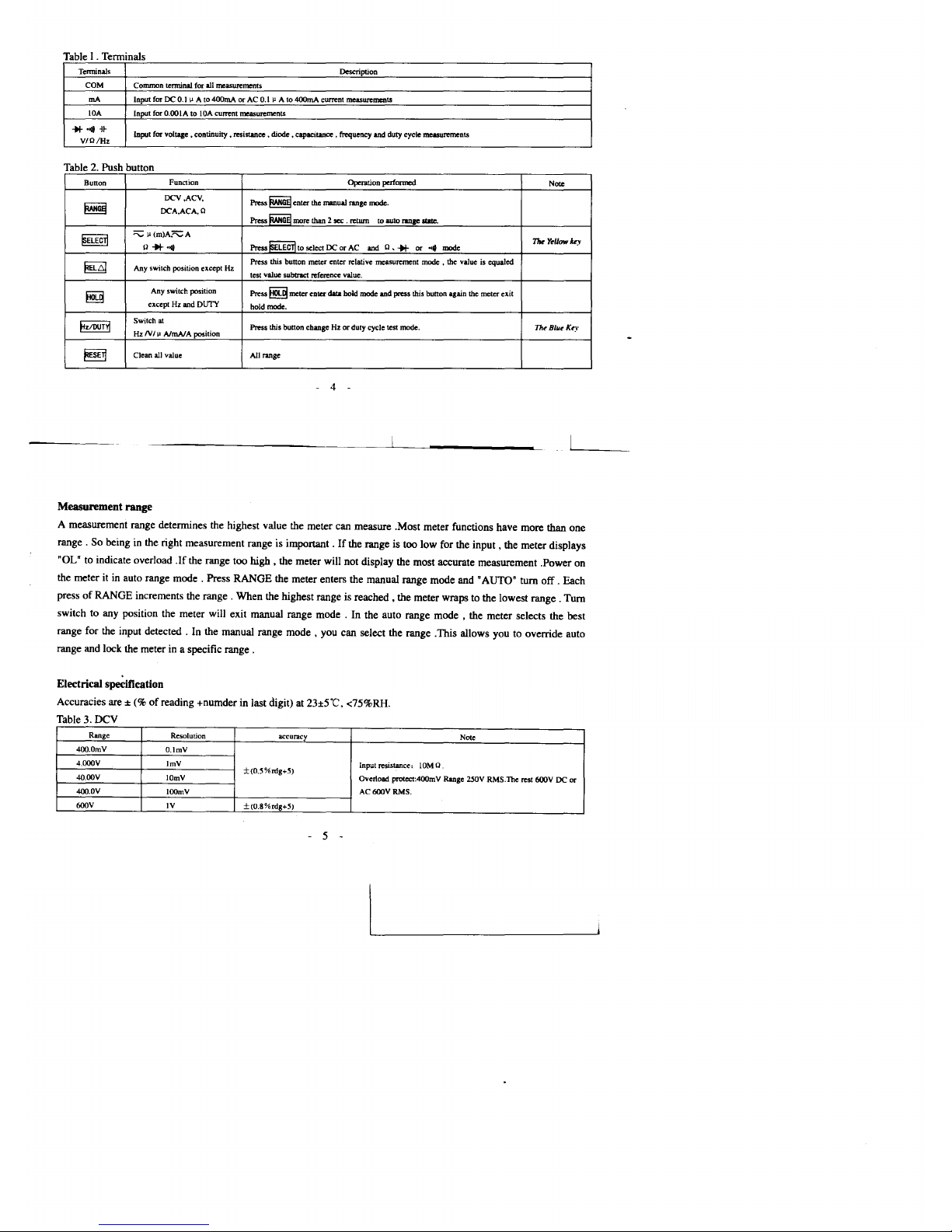
Terminals
Description
COM
Common
terminal
for
all
measurements
rnA
Input
forOC0.1~A
to
400mA
orAC0.111A
to
400mA
current
measurements
lOA
Input
for
0.001AtolOA
current
measurements
*'O/I-j~
Input
for
voltage. continuity. resistance. diode .capacitance.
frequency
and
duty
cycle
measurements
VIC
1Hz
a e s utton
Button
Function
Ope..tion performed
NolC
DCV,ACV,
Press
~
enter
the
manual
range
mode.
~
DCA,ACA,C
Press
RANGEl
more
than
2sec . return
to auto
ranae
1tIIe.
~ELECTI
""""'1J(m)A."""A
Press
mECTl
to
selectOCor
AC
TM
Yellow
key
0"""0/1
and 0
......or...
mode
~
Press
this
button
meter
enler
relative
measurement
mode
•
the
valueisequaled
Any
switch position except Hz
tcst
value
subtract
reference
value.
~
Any
switch p>sition
Press
~
meter
eDter
data
hold
mode
and
press
this
button
again
the
meter
exit
exceptHzand
DUTY
hold mode.
FZIOUT~
Switch
at
Press
this
button
changeHzor
duty
cycle test
mode.
Th~
Blu~Ke)'
HzIVIi!
AJrnAJ
A position
~
Clean
all
value
AlllaOge
l'
bl 2 Pu h b
4
Measurement range
A measurement range detennines the highest value the meter can measure ,Most meter functions have more than one
range.
So being in the right measurement range is important.Ifthe range is too low for the
input,
the meter displays
"OL" to indicate overload
.If
the range too high • the meter will not display the most accurate measurement .Power on
the meter it
in
auto range
mode.
Press RANGE the meter enters the manual range mode and "AUTO" turn
off.
Each
press
of
RANGE increments the
range.
When the highest range is
reached.
the meter wraps to the lowest
range.
Turn
switch to any position the meter will exit manual range
mode.
In the auto range
mode.
the meter selects the best
range for the input
detected.
In the manual range
mode.
you can select the range .This allows you to override auto
range and lock the meter in a specific
range.
Electrical specification
Accuracies are ±(%of
reading +numder in last digit) at 23±5"C, <75%RH.
Table 3
Dey
Range
Resolution
accuracy
Note
400.OmV
O.lmV
4.000V
ImV
Input
resistance;
IOMO.
±(O.5%rdg+5)
4O.00V
IOmV
Overload protect:4OOmV Range 250V RMS.The rest 600V DC or
4OO.0V
1000V
AC600VRMS.
600V
IV
+(O.8%rdg+5)
5
Page 4
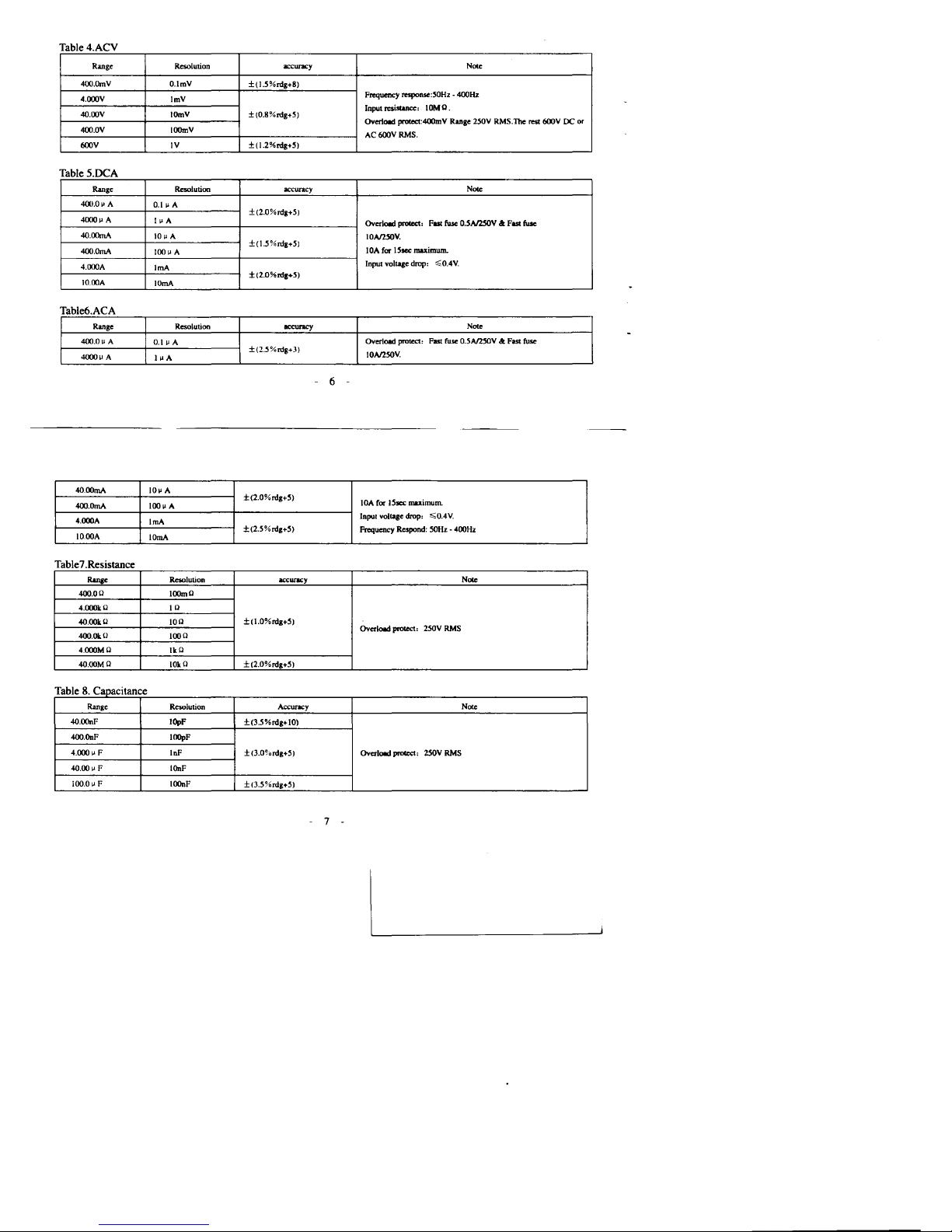
Table 4 ACV
Range
Resolution
accuracy
Noce
4OO.OmV
O.lmV
±(1.5%nlg+8)
4.OOOV
ImV
Frequency response:50Hz - 400Hz
Input
resistance:
IOMO.
4O.00V IOmV
±{O.8%rdg+5}
Overlood protect:4OOmV Range
2.50V
RMS.The rest 600V DC
or
4OO.0V
1000V
AC600VRMS.
600V
IV
±(1.2%nlg+5)
Table 5 DCA
Range Resolution
accuracy
Noce
400.0"
A
0.1"
A
±(2.0%rdg+5)
4000"
A
I"
A
Overlood
prole<I'
FISl fuse
O.5A125OVa:FISl fuse
4O.00mA
10"
A
IOAI25OV.
±(l.5%nlg+5)
lOA
for
15sec
maximum.
4OO.0mA
100"
A
4.000A
IrnA
Input
voltage
drop:
";O.4V.
±(2.0%nlg+5)
10.OOA
lOrnA
Table6ACA
Range
Resolution
occuracy
Nole
4OO.0u
A
0.1"
A
Overload
protect: FISl fuse 0.5A125OV
a:
FISl fuse
±(2.5%rdg+3)
IOAl25OV.
4000"
A
1
"A
6
4O.00mA
10"
A
±(2.0%nlg+5)
lOA
for
lSscc
maximum.
4OO.0mA
100"
A
4.oooA
101"'1
vollage drop,
";0.4V.
IrnA
±(2.5%nlg+5)
Frequeney Respond: 50Hz - 400Hz
lO.ooA
10mA
Table7 Resistance
Range Resolution
accuracy
Noce
400.00
100m0
4.oookO
10
4O.ookO
100
±(1.0%nIg+5)
Overlood protect, 250V RMS
4OO.OkO
1000
4.oooMO
IkO
4O.00MO 10k 0
±(2.0%nlg+5)
T bl 8 Ca e aoacllance
Range
Resolution
Accuracy Note
4O.00nF IOpF
±(3.5%nlg+IOl
4OO.OnF
1000F
4.000"
F
10F
±<3.0%nlg+5)
Overlood prole<I,
25QV
RMS
40.00"
F
IOnF
100.0"
F
1000F
±<3.5%nlg+5)
7
Page 5

Table 9 Diode
Range
1JreIcription
Note
"*
Display
read
approx. forward voltage
of
diode
Forward
DC
cum:nt
appro"'.
1.5mA;
ReversedDCvoltage
appro"'.
1
.sY.
Overload protect,250V RMS
Table IO.Frequenc and Duty
Range Resolution
Accuracy Sensitivity
NOIe
5.12Hz-IOMHz
O.OOIH,-lOkHz
±(O.l
%rdg+5)
'i;
IMH"
O.7V RMS;
:>
IMHz: 1.5V
RMS
Overload prolect,
250V
RMS
DUTY CYCLE,
O.I\fto99.9%
±(2.5%rdg+5)
1.5V RMS
Duty Cycle: 10Hz
-1kHz
Operation
AC voltage measurement
I. Set the rotary switch to
"""'
V " position.
2.
Connect the black test lead to "COM" tenninal and the red test lead
to"
"*
.",
-If-
V/ Q
1Hz"
tenninal .
3.
Touch the probes to the test points and reading the display ,at same time,you can press HzlDUTY bullon obtain the
signal frequency and duty
of
voltage isinmeasured.
OC voltage measurement
I.
Set the rotary switch to '
-:-=-:V
" position.
- 8 -
2. Connect the black test lead to "
COM"
tenninal and the red test lead
to"
"*.."
-If-
VIQ
1Hz
" terminal .
3.
Touch the probes to the test points and read the display ,at same time,you can press HzlDUTY bUllon obtain the
signal frequency and duty
of
voltage is in measured.
OC / AC Current measurement
L1'\
Warning
To
avoid damage to the meterorinjuryifthe fuse blows , never attemptanin-circuit current measurement
where
the open-circuit potential to
earth
is greater
than
6OOV.Toavoid damage to the
meter,
check the meter's
fuses
before proceeding.
Use
the proper
terminals,
function,
and
range for your
measurement.
Never place
the probes in parallel with a circuit
or
component when
the
leads
are
plugged into the current terminais •
I. Turn off power to the circuit. Discharge all high-voltage capacitors .
2.
Set the rotary switch to"
"'C;
jJ
A"
, "
~rnA
"or
";::;;:;A"
position
3. Press SELECT (yellow) to select OC or AC
mode.
4. Connect the black test lead to " COM" tenninal and the red test lead to ' rnA"
or"
A"
tenninal.
5. Touch the probes to the test points , turn on to the circuit and read the display ,at same time, you can press
HzlDUTY bullon obtain the signal frequency and duty
of
ClllTellt
is in measured
..
Resistance measurement
L1'\
Caution
--
9 -
Page 6
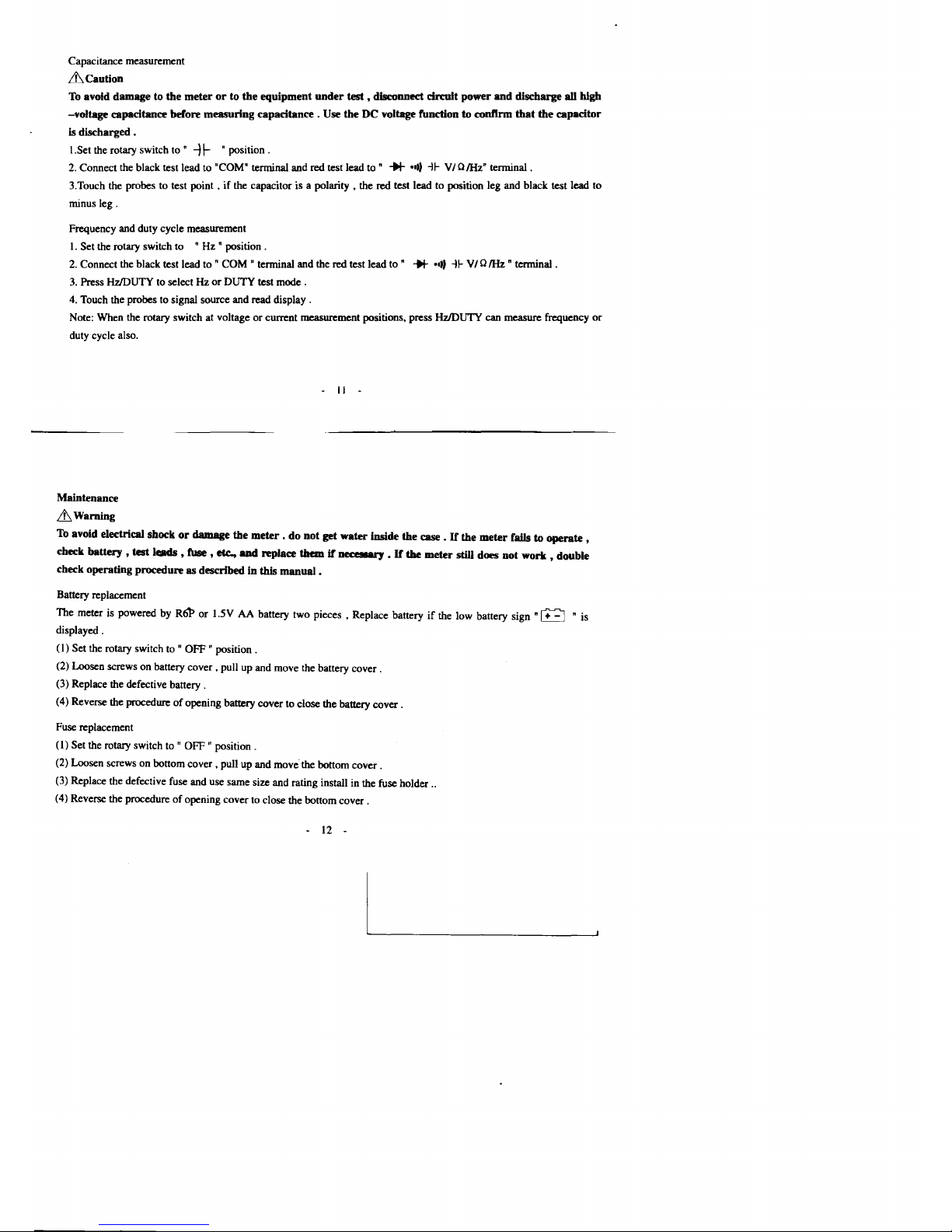
Capacitance measurement
& Caution
To
avoid damage to the
meterorto the equipment
under
test • disconnect
drmlt
power
and
discharge all blgb
-voltage capacitance before measuring
capacitance.
Use the DC voltage functiontoconftrm
that
the capacitor
is discharged .
I.Set the rotary switch
to"
-)1-
"position.
2. Connect the black test lead to "COM" terminal and red test lead
to"
+I-
.,,)
-1I-
VIo1Hz"
terminal.
3.Touch the probes to test
point.ifthe capacitor is a
polarity,
the red test lead to position leg and black test lead to
minus
leg.
Frequency and duty cycle measurement
I.
Set the rotary switch to
"Hz"
position.
2. Connect the black test lead to
"
COM"
terminal and the red test lead
to"
+I-
.,,)
-II-
VI01Hz
" terminal .
3.
Press HzJDUTY to selectHzor
DUTY
test mode .
4. Touch the probes to signal source and read
display.
Note: When the rotary switch at voltageorcurrent measurement positions, press HzJDUTY can measure frequency
or
duty cycle also.
II
Maintenance
&Wamlng
To
avoid electrical shockordamage the
meter,donot
get water inside the case . H the
meter
falls to operate •
check
battery
• test leads • fuse • etc.,
and
replace themifneceIIIIU"Y
• H
the
meter
still does
not
work • double
check operating procedure
as
described in this manual .
Battery replacement
The meter is powered by
R6l>or1.5VAAbattery two pieces • Replace batteryifthe low battery sign
"~
"is
displayed .
(I)
Set the rotary switch to "
OFF"position.
(2) Loosen screws on battery
cover.
pull up and move the battery
cover.
(3) Replace the defective battery .
(4) Reverse the procedure
of
opening battery cover to close the battery
cover.
Fuse replacement
(I)
Set the rotary switch to "
OFF"position.
(2) Loosen screws on bottom
cover,
pull up and move'the bottom
cover.
(3) Replace the defective fuse and use same size and rating install in the fuse holder ..
(4) Reverse the procedure
of
opening cover to close the bottom
cover.
12 -
 Loading...