

Page 1
PCIe/PXIe-8638
PCIe to PXIe Extension Kit
User’s Manual
Manual Rev.: 2.00
Revision Date: Nov. 28, 2014
Part No: 50-17050-1000
Advance Technologies; Automate the World.
Page 2

Revision History
Revision Date Description
2.00 Dec. 29, 2014 Initial release
ii
Page 3

PCIe/PXIe-8638
Preface
Copyright 2014 ADLINK Technology, Inc.
This document contains proprietary information protected by copyright. All rights are reserved. No part of this manual may be reproduced by any mechanical, electronic, or other means in any form
without prior written permission of the manufacturer.
Disclaimer
The information in this document is subject to change without prior
notice in order to improve reliability, design, and function and does
not represent a commitment on the part of the manufacturer.
In no event will the manufacturer be liable for direct, indirect, special, incidental, or consequential damages arising out of the use or
inability to use the product or documentation, even if advised of
the possibility of such damages.
Environmental Responsibility
ADLINK is committed to fulfill its social responsibility to global
environmental preservation through compliance with the European Union's Restriction of Hazardous Substances (RoHS) directive and Waste Electrical and Electronic Equipment (WEEE)
directive. Environmental protection is a top priority for ADLINK.
We have enforced measures to ensure that our products, manufacturing processes, components, and raw materials have as little
impact on the environment as possible. When products are at their
end of life, our customers are encouraged to dispose of them in
accordance with the product disposal and/or recovery programs
prescribed by their nation or company.
Trademarks
Product names mentioned herein are used for identification purposes only and may be trademarks and/or registered trademarks
of their respective companies.
Preface iii
Page 4
Conventions
Take note of the following conventions used throughout this
manual to make sure that users perform certain tasks and
instructions properly.
Additional information, aids, and tips that help users perform
tasks.
NOTE:
NOTE:
Information to prevent minor physical injury, component damage, data loss, and/or program corruption when trying to com-
CAUTION:
WARNING:
plete a task.
Information to prevent serious physical injury, component
damage, data loss, and/or program corruption when trying to
complete a specific task.
iv Preface
Page 5

PCIe/PXIe-8638
Table of Contents
Revision History...................................................................... ii
Preface .................................................................................... iii
List of Figures ....................................................................... vii
List of Tables.......................................................................... ix
1 Introduction ........................................................................ 1
1.0.1 Controlling PXI with PCI Express ............................... 1
1.1 Specifications....................................................................... 2
1.1.1 PCIe-8638 Host Adapter ............................................ 2
1.1.2 PXIe-8638 (on extension PXI™ chassis) ................... 2
1.1.3 Power Requirements .................................................. 2
1.1.4 Operating and Storage Environments ........................ 3
1.2 Features............................................................................... 3
1.3 Applications ......................................................................... 4
1.4 Platform Services Installation .............................................. 4
2 Getting Started. .................................................................. 5
2.1 Package Contents ............................................................... 5
2.2 Installation Environment ...................................................... 5
2.3 Installing the PCIe-8638 on a Host Computer ..................... 6
2.4 Installing PXIe-8638 to a PXIe chassis................................ 8
2.5 Cabling Host Computer to a PXI Chassis............................ 9
2.6 Power ON/OFF Sequence................................................. 10
3 Hardware Information ...................................................... 11
3.1 Functional Block Diagram.................................................. 11
3.2 PCIe-8638 Layout, Connectors and Jumpers.................... 11
3.3 PXIe-8638 Layout, Connectors and Jumpers.................... 12
v
Page 6

A Appendix: Troubleshooting (FAQ) .................................. 15
Important Safety Instructions.............................................. 19
Getting Service ..................................................................... 21
vi
Page 7

PCIe/PXIe-8638
List of Figures
Figure 2-1: PCIe-8638 to Host PC Installation ................................... 7
Figure 2-2: PXIe-8638 to PXI™ Chassis Installation Diagram........... 8
Figure 2-3: PCIe x8 Cable Assembly ................................................. 9
Figure 3-1: PCIe to PXIe Extension Kit Functional Block Diagram .. 11
Figure 3-2: PCIe-8638 Mechanical Layout....................................... 11
Figure 3-3: PXIe-8638 Mechanical Layout....................................... 12
Figure A-1: Bus Number Information Result..................................... 16
List of Figures vii
Page 8

This page intentionally left blank.
viii List of Figures
Page 9

PCIe/PXIe-8638
List of Tables
Table 2-1: PCIe-8638 to Host PC Installation Legend ...................... 7
Table 3-1: PCIe-8638 Mechanical Layout Legend.......................... 11
Table 3-2: PCIe-8638 Connectors, Switches, and LEDs ................ 12
Table 3-3: PXIe-8638 Connectors and LEDs.................................. 13
Table A-1: PCI Bus Number Requirements .................................... 16
List of Tables ix
Page 10

This page intentionally left blank.
x List of Tables
Page 11

PCIe/PXIe-8638
1 Introduction
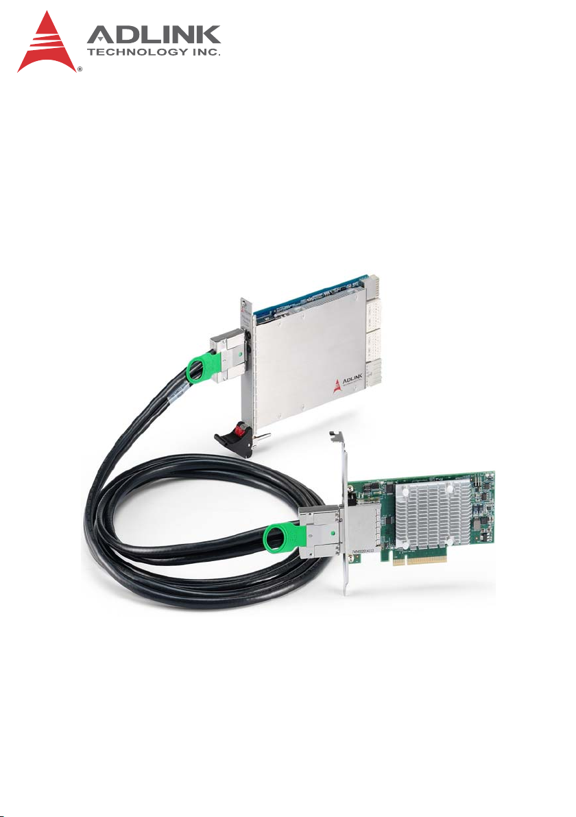
The PCIe-PXIe-8638 PCI Express to PXI Express extension kit
provides control of PXI Express modules installed in a PXIe chassis using high bandwidth PCI Express technology. The extension
kit provides up to 4GB/s bandwidth using PCIe Gen 2 x8 signaling.
With comprehensive hardware and software transparency, the
extension kit enables fast and convenient detection of any PXI
cards installed in the system, requiring no additional drivers or
software.
The host PC may be separated from the PCI Express chassis by
up to five meters using high-quality shielded twisted copper
cables. The robust and reliable PCIe to PXIe Extension Kit is
suited for portable test and measurement applications with
high-density I/O requirement and in hazardous industrial control
and automation environments.
1.0.1 Controlling PXI with PCI Express
Based on PCI Express technology, the PCIe to PXIe Extension Kit
provides bus extension capability through its high-speed differential signal interface.
The PCIe-PXIe-8638 PCI Express-to-PXI Express expansion kit
provides additional PXI instruments slots to the host computer by
implementing a PCI Express-based control of PXI modules.The
technology consists of a PCIe-8638 host adapter installed in the
host computer, a PCIe x8 cable, and a PXIe-8638, a remote controller with the 3U (Eurocard) expansion module. The PCIe-8638
comes in a PCI Express x8 footprint and equips with PCIe x8
cable connector.
Introduction 1
Page 12

1.1 Specifications
1.1.1 PCIe-8638 Host Adapter
X PCI Express Base Specifications rev. 1.0a compliant
X PCI Express gen 2 x8 link with 4GB/s data throughput
X Extended distance of up to 5 meters
X Low-profile PCI Express card 142(W) x 69(H) mm
1.1.2 PXIe-8638 (on extension PXI™ chassis)
X PXI-5 PXI Express hardware specification Rev.1.0 compli-
ant
X PCIe Gen 2 x8 cable connector with 4GB/s data throughput
X PXI Express link capability:
Z Four links configuration: x4 x4 x4 x4
Z Two links configuration: x16 x8
X 175 (W) x 107 (H) mm
1.1.3 Power Requirements
X PCIe-8638
Typical Power 4.0 W
Maximum Power 8.0 W
X PXIe-8638
Power Rail 12 V 3.3 V
Typical Current 0.85 A 1.3 A
Maximum Current 1.7 A 2.6 A
2 Introduction
Page 13

PCIe/PXIe-8638
1.1.4 Operating and Storage Environments
X Operating temperature: 0°C to 55°C
X Storage temperature: -20°C to 70°C
X Relative humidity: 10% to 90%, non-condensing
Insertion loss in sockets and accessory cable connectors may
increase after frequent multiple insertion/removals, degrading
CAUTION:
signal integrity of high speed PCI Express transmission. For
each PCIe-PXIe-8638 socket or accessory cable connector,
more than 200 connections/disconnections can impede functionality and performance.
Insertion loss in sockets and accessory cable connectors may
increase after frequent multiple insertion/removals, degrading signal integrity of high speed PCI Express transmission. For each
PCIe-PXIe-8638 socket or accessory cable connector, more than
200 connections/disconnections can impede functionality and performance.
1.2 Features
X PXI-5 PXI Express hardware specification rev.1.0 compliant
X PCI Express® Base Specifications Rev. 1.0a
X Maximum system throughput 4 GB/s
X PXI Express link capability:
Z Four links configuration: x4 x4 x4 x4
Z Two links configuration: x16 x8
X Expansion up to 5 m (expansion cables at 2 or 5 m)
X Comprehensive hardware and software transparency
Introduction 3
Page 14

1.3 Applications
These extension systems are suitable for:
X Electronics manufacturing testing
X High-density I/O systems
X Industrial automation and control
X Military and aerospace
X Testing systems for remote and/or harsh environments
X Video capture
1.4 Platform Services Installation
It is recommended that ADLINK Platform Services applications be
installed prior to operation. Please see the ADLINK document PXI
Platform Services User’s Manual for details.
This page intentionally left blank.
4 Introduction
Page 15

2 Getting Started.
Diagrams and images of equipment mentioned are used for
reference only. Actual system appearance may vary.
NOTE:
NOTE:
2.1 Package Contents
X PCI-8638 (PCI Express x8 host adapter for extension kit)
X PXIe-8638 (PXI Express remote controller)
X PCI Express x8 cable assembly (2m or 5m)
X Quick Start Guide
If any of the items on the contents list are missing or damaged,
contact your ADLINK dealer.
NOTE:
NOTE:
2.2 Installation Environment
PCIe/PXIe-8638
Whenever unpacking and preparing to install any equipment
described in this manual, please refer to the Important Safety
Instructions chapter of this manual.
Only install equipment in well lit areas on flat, sturdy surfaces with
access to basic tools such as flat and cross head screwdrivers.
The PCIe to PXIe Extension Kit contains several electrostatic sensitive components that can be easily damaged by static electricity.
For this reason, the cards and chassis should be handled on a
grounded anti-static mat and the operator should wear an
anti-static wristband during the unpacking and installation procedure.
Please also inspect the components for apparent damage.
Improper shipping and handling may cause damage to the compo-
Getting Started. 5
Page 16

nents. Be sure there is no shipping and handling damage on the
components before continuing.
Do not apply power to any equipment if it has been damaged.
CAUTION:
2.3 Installing the PCIe-8638 on a Host Computer
1. Power-off your host computer.
2. Unscrew the housing of your host computer using a
(cross-head or flat-head) screwdriver. Open the housing.
3. Locate your PCI Express® extension card (PCIe-8638)
and remove it from its packaging. (Please wear
anti-static gloves and use an anti-static surface when
handling the card).
4. Install the PCIe-8638 in an available x8 or x16 PCI
Express® slot in your host computer. Be sure to firmly
attach the PCIe-8638’s bracket to the backplane of the
host PC.
5. Close the chassis and re-install its housing screws.
6 Getting Started.
Page 17

B
PCIe/PXIe-8638
A
C
Figure 2-1: PCIe-8638 to Host PC Installation
Item Description
A Industrial PC or Desktop PC with x8 PCI Express Slot
B PCIe-8638 (PCI Express host card)
C x8 PCI Express Slot
Table 2-1: PCIe-8638 to Host PC Installation Legend
Getting Started. 7
Page 18

2.4 Installing PXIe-8638 to a PXIe chassis
1. Remove the cover panel of the system slot.
2. Locate the PXIe-8638 and remove from packaging.
(Please wear anti-static gloves and use an anti-static
surface when handling the card).
3. Insert the PXIe-8638 into the PXI™ system slot and
tighten the bracket-retaining screws on the top and bottom of the panel to fasten the PXIe-8638 to the chassis.
Figure 2-2: PXIe-8638 to PXI™ Chassis Installation Diagram
The PXIe-8638 must be installed into the PXI™ system slot,
peripheral slots may not be used
WARNING:
8 Getting Started.
Page 19

PCIe/PXIe-8638
2.5 Cabling Host Computer to a PXI Chassis
Now that you have successfully installed the PCIe-8638 into the
Host computer and installed the PXIe-8638 in the PXIe chassis,
you may connect the host PC and PXI chassis with a PCIe cable
assembly.
Removing the PCIe cable assembly after the system is
powered on may cause system errors or data loss. If the
CAUTION:
cable is unplugged improperly, reconnect it and reboot
the host PC and PXI chassis.
Figure 2-3: PCIe x8 Cable Assembly
1. Connect the cable assembly to the PCIe connector on
the bracket of the PCIe-8638 located in the host PC.
2. Connect the other end of the cable assembly to the con-
nector of the PXIe-8638 installed into the system slot of
the PXIe chassis.
Getting Started. 9
Page 20

2.6 Power ON/OFF Sequence
To power-on the PCIe to PXIe Extension Kit:
1. Ensure that the extension cable is properly connected to
the host PC and PXIe chassis.
2. Power on the PXIe chassis.
3. When status LEDs of the PXI Express chassis and all
installed modules indicate ready, power on the host PC
.
DO NOT remove the cable after the system and PXIe
chassis are powered on. Disconnecting the cable while
CAUTION:
As the PCIe to PXIe Extension Kit is equipped with a standard
PCIe switch, the BIOS will identify each device behind the switch
and assign resources to each during startup. Thus the PXI chassis
must be powered up in order to acquire appropriate resources
from the BIOS.
To power down the PCIe to PXIe Extension Kit:
the system is running may cause unpredictable system
errors and/or system crash.
1. Power down the host PC.
2. Power down the PXIe chassis.
DO NOT power down the PXIe chassis until the host PC
is powered off. If the PXIe chassis is powered off while
CAUTION:
10 Getting Started.
the host PC is on, the host PC may hang or crash.
Page 21

PCIe/PXIe-8638
3 Hardware Information
3.1 Functional Block Diagram
Figure 3-1: PCIe to PXIe Extension Kit Functional Block Diagram
3.2 PCIe-8638 Layout, Connectors and Jumpers
C
DIP
ON
72
1 2 3 4
A
B
Figure 3-2: PCIe-8638 Mechanical Layout
A PCIe x8 external cabling
B PCIe x8 edge finger
C SW1
Table 3-1: PCIe-8638 Mechanical Layout Legend
Hardware Information 11
Page 22

Connector/Switch/LED Description
Off: No power
STATUS
HOST
(Link status between
PCIe-8638 and PXIe-8638)
SW1
Table 3-2: PCIe-8638 Connectors, Switches, and LEDs
Orange: Power OK
Green: PXIe-8638 present
Off: No link
0.5Hz Blinking: Link in PCIe Gen1 signaling
1Hz Blinking: Link in PCIe Gen2 signaling
Default settings are ON: Pin3 and OFF: Pins
1,2,4
3.3 PXIe-8638 Layout, Connectors and Jumpers
CN5
Figure 3-3: PXIe-8638 Mechanical Layout
Connector/Jumper/LED Description
CN5 PCIe x8 External cabling
12 Hardware Information
Page 23

Connector/Jumper/LED Description
Off: No power
PWR/PRSNT
LINK
(Link status between
PCIe-8638 and
PXIe-8638)
Table 3-3: PXIe-8638 Connectors and LEDs
Orange: Power OK
Green: PCIe-8638 present
Off: No link
0.5Hz Blinking: Link in PCIe Gen1 signaling
1Hz Blinking: Link in PCIe Gen2 signaling
PCIe/PXIe-8638
Hardware Information 13
Page 24

This page intentionally left blank.
14 Hardware Information
Page 25

PCIe/PXIe-8638
Appendix A Troubleshooting (FAQ)
This chapter describes frequently asked questions that may assist
in solving minor problems that may be encountered.
Question: What is the maximum extension length of
PCIe-PXIe-8638?
Answer: ADLINK provides cable accessories for PCIe-PXIe-8638
in 2 and 5 meter lengths, with maximum cable length 5
meters.
Question: When using ADLINK PCIe-PXIe-8638, are there any
additional drivers or software required to install?
Answer: Yes, ADLINK PXI Platform Services supports
PCIe-PXIe-8638 including PCIe-PXIe-8638 SMBus controller drivers and PXI software framework.
ADLINK PXI Platform Services can be downloaded from
PCIe-PXIe-8638 product page of ADLINK website.
Question: Which link configuration of the PXI Express system slot
does the PCIe-PXIe-8638 support, 4- or 2-link? How are the
associated settings configured?
Answer: The PCIe-PXIe-8638 acts as a generic PXI Express sys-
tem controller that supports both 4-link and 2-link PXI
Express system slots. It detects the backplane and configures automatically without any settings required.
Question: Are there any compatibility concerns with the
PCIe-PXIe-8638? How can a host PCbe selected that will
be most compatible with the PCIe-PXIe-8638?
Troubleshooting (FAQ) 15
Page 26

Answer: Limited PCI bus availability is the major concern about
compatibility. Available PCI bus numbers assigned by system BIOS may exceed PCI bus numbers required by the
PCIe-PXIe-8638 and PXI Express chassis. If PCI bus numbers are occupied, the system may not boot correctly or
devices not detected.
Theoretically, PC systems implementing PCI Express can support
up to 256 bus numbers. However, maximum PCI bus numbers of many PC systems are frequently limited by system
BIOS based on system design or architecture. Conversely,
the PXI Express chassis consumes many PCI bus numbers. Each PXI Express peripheral slot reserves a PCI bus
number and PCI Express switches of PXI Express chassis
also occupy several PCI bus numbers. Some peripheral
modules may also consume PCI bus numbers. PCI bus
number requirements for ADLINK PXI Express chassis are
as shown.
Model
PCIe-PXIe-8638 + PXES-2590 27
PCIe-PXIe-8638 + PXES-2780 44
Table A-1: PCI Bus Number Requirements
PCI Bus Number
Requirement
3rd party utilities like System Information Viewer (http://rh-soft-
ware.com/) are able to check available PCI bus numbers in
system BIOS (Run SIV>>PCI Bus>>ACPI Buses), as
shown.
Figure A-1: Bus Number Information Result
16 Troubleshooting (FAQ)
Page 27

PCIe/PXIe-8638
Question: One or more modules in PXI Express chassis con-
nected via PCIe-PXIe8638 are missing from Windows
Device Manager. How to best solve this or other compatibility problems (like no boot)?
Answer: Due to flexibility and variety of systems with PCI Express
expansion, most compatibility issues are related with abnormal device detection or resource assignment done by system BIOS. The following suggestions may help solve
frequently encountered issues.
X Check PCIe-PXIe-8638 and cable are properly installed
X Check any abnormal LED status of PCIe-PXIe-8638. (See
“PCIe-8638 Layout, Connectors and Jumpers” on page 11.)
X Check PCIe-PXIe-8638 cable are free of broken, bend, or
dirty/broken connector
X Make sure there are sufficient PXI Express bus numbers
available
X Occasionally updated BIOS system fixes resource limitation
issues
X Try different installation sequence of modules in PXI
Express chassis
X Try different PCI Express slot or different host PC (different
system BIOS)
X Remove some modules to free resources
Question: Does the PCIe-PXIe-8638 support Linux?
Answer: The PCIe-PXIe-8638 is designed as a standard
PCIe-to-PCIe bridge should still support most modern Linux
Kernels without additional driver requirements. Since the
PXI Express software specification is based on a Windows
environment, however, PXI software framework and SMBus
controller of PCIe-PXIe-8638 are not operable under Linux.
Troubleshooting (FAQ) 17
Page 28

This page intentionally left blank.
18 Troubleshooting (FAQ)
Page 29

PCIe/PXIe-8638
Important Safety Instructions
For user safety, please read and follow all instructions,
WARNINGS, CAUTIONS, and NOTES marked in this manual
and on the associated equipment before handling/operating the
equipment.
X Read these safety instructions carefully.
X Keep this user’s manual for future reference.
X Read the specifications section of this manual for detailed
information on the operating environment of this equipment.
X When installing/mounting or uninstalling/removing
equipment:
Z Turn off power and unplug any power cords/cables.
X To avoid electrical shock and/or damage to equipment:
Z Keep equipment away from water or liquid sources;
Z Keep equipment away from high heat or high humidity;
Z Keep equipment properly ventilated (do not block or
cover ventilation openings);
Z Make sure to use recommended voltage and power
source settings;
Z Always install and operate equipment near an easily
accessible electrical socket-outlet;
Z Secure the power cord (do not place any object on/over
the power cord);
Z Only install/attach and operate equipment on stable
surfaces and/or recommended mountings; and,
Z If the equipment will not be used for long periods of time,
turn off and unplug the equipment from its power source.
Important Safety Instructions 19
Page 30

X Never attempt to fix the equipment. Equipment should only
be serviced by qualified personnel.
X A Lithium-type battery may be provided for uninterrupted,
backup or emergency power.
RISK OF EXPLOSION IF BATTERY IS REPLACED BY AN
INCORECT TYPE. DISPOSE OF USED BATTERIES
CAUTION:
ACCORDING TO THEIR INSTRUCTIONS.
X Equipment must be serviced by authorized technicians
when:
Z The power cord or plug is damaged;
Z Liquid has penetrated the equipment;
Z It has been exposed to high humidity/moisture;
Z It is not functioning or does not function according to the
user’s manual;
Z It has been dropped and/or damaged; and/or,
Z It has an obvious sign of breakage.
20 Important Safety Instructions
Page 31

Getting Service
Contact us should you require any service or assistance.
ADLINK Technology, Inc.
Address: 9F, No.166 Jian Yi Road, Zhonghe District
New Taipei City 235, Taiwan
ᄅקؑխࡉ৬ԫሁ 166 ᇆ 9 ᑔ
Tel: +886-2-8226-5877
Fax: +886-2-8226-5717
Email: service@adlinktech.com
Ampro ADLINK Technology, Inc.
Address: 5215 Hellyer Avenue, #110
San Jose, CA 95138, USA
Tel: +1-408-360-0200
Toll Free: +1-800-966-5200 (USA only)
Fax: +1-408-360-0222
Email: info@adlinktech.com
ADLINK Technology (China) Co., Ltd.
Address: Ϟ⍋Ꮦ⌺ϰᮄᓴ∳催⾥ᡔು㢇䏃 300 ো(201203)
300 Fang Chun Rd., Zhangjiang Hi-Tech Park
Pudong New Area, Shanghai, 201203 China
Tel: +86-21-5132-8988
Fax: +86-21-5132-3588
Email: market@adlinktech.com
ADLINK Technology Beijing
Address: ࣫ҀᏖ⍋⎔Ϟഄϰ䏃 1 োⲜ߯ࡼ E ᑻ 801 ᅸ(100085)
Rm. 801, Power Creative E, No. 1 Shang Di East Rd.
Beijing, 100085 China
Tel: +86-10-5885-8666
Fax: +86-10-5885-8626
Email: market@adlinktech.com
PCIe/PXIe-8638
ADLINK Technology Shenzhen
Address: ⏅ഇᏖቅ⾥ᡔು催ᮄϗ䘧᭄ᄫᡔᴃು
Tel: +86-755-2643-4858
Fax: +86-755-2664-6353
Email: market@adlinktech.com
LiPPERT ADLINK Technology GmbH
Address: Hans-Thoma-Strasse 11, D-68163
Mannheim, Germany
Tel: +49-621-43214-0
Fax: +49-621 43214-30
Email: emea@adlinktech.com
A1 2 ὐ C (518057)
2F, C Block, Bldg. A1, Cyber-Tech Zone, Gao Xin Ave. Sec. 7
High-Tech Industrial Park S., Shenzhen, 518054 China
Getting Service 21
Page 32

ADLINK Technology, Inc. (French Liaison Office)
Address: 6 allée de Londres, Immeuble Ceylan
91940 Les Ulis, France
Tel: +33 (0) 1 60 12 35 66
Fax: +33 (0) 1 60 12 35 66
Email: france@adlinktech.com
ADLINK Technology Japan Corporation
Address: ͱ101-0045 ᵅҀ䛑ҷ⬄⼲⬄䤯ފ⬎ 3-7-4
Tel: +81-3-4455-3722
Fax: +81-3-5209-6013
Email: japan@adlinktech.com
ADLINK Technology, Inc. (Korean Liaison Office)
Address: 137-881 昢殾柢 昢爎割 昢爎堆嵢 326, 802 (昢爎壟, 微汾瘶捒娯)
Tel: +82-2-2057-0565
Fax: +82-2-2057-0563
Email: korea@adlinktech.com
ADLINK Technology Singapore Pte. Ltd.
Address: 84 Genting Lane #07-02A, Cityneon Design Centre
Tel: +65-6844-2261
Fax: +65-6844-2263
Email: singapore@adlinktech.com
ADLINK Technology Singapore Pte. Ltd. (Indian Liaison Office)
Address: #50-56, First Floor, Spearhead Towers
Malleswaram, Bangalore - 560 055, India
Tel: +91-80-65605817, +91-80-42246107
Fax: +91-80-23464606
Email: india@adlinktech.com
⼲⬄ 374 ɛɳ 4F
KANDA374 Bldg. 4F, 3-7-4 Kanda Kajicho,
Chiyoda-ku, Tokyo 101-0045, Japan
802, Mointer B/D, 326 Seocho-daero, Seocho-Gu,
Seoul 137-881, Korea
Singapore 349584
Margosa Main Road (between 16th/17th Cross)
ADLINK Technology, Inc. (Israeli Liaison Office)
Address: 27 Maskit St., Corex Building
PO Box 12777
Herzliya 4673300, Israel
Tel: +972-54-632-5251
Fax: +972-77-208-0230
Email: israel@adlinktech.com
ADLINK Technology, Inc. (UK Liaison Office)
Tel: +44 774 010 59 65
Email: UK@adlinktech.com
22 Getting Service
 Loading...