

Page 1
PCI-8254 / PCI-8258
DSP-Based 4/8
Advanced Motion Control Card
User manual
Ver si on: 2.00
Updated: August 13, 2014
P/N: 50-15085-1000
Advance Technologies; Automate the World.
Page 2

Revision History
Revision Date Description
2.00 2014-08-13 First release
ii
Page 3

PCI-8254 / PCI-8258
Preface
Copyright 2014 ADLINK Technology, Inc.
This document contains proprietary information protected by
copyright. All rights are reserved. No part of this manual may be
reproduced by any mechanical, electronic, or other means in any
form without prior written permission of the manufacturer.
Disclaimer
The information in this document is subject to change without prior
notice in order to improve reliability, design, and function and does
not represent a commitment on the part of the manufacturer.
In no event will the manufacturer be liable for direct, indirect,
special, incidental, or consequential damages arising out of the
use or inability to use the product or documentation, even if
advised of the possibility of such damages.
Environmental responsibility
ADLINK is committed to fulfill its social responsibility to global
environmental preservation through compliance with the
European Union's Restriction of Hazardous Substances (RoHS)
directive and Waste Electrical and Electronic Equipment (WEEE)
directive. Environmental protection is a top priority for ADLINK.We
have enforced measures to ensure that our products,
manufacturing processes, components, and raw materials have as
little impact on the environment as possible. When products are at
their end of life, our customers are encouraged to dispose of them
in accordance with the product disposal and/or recovery programs
prescribed by their nation or company.
Trademark
Product names mentioned herein are used for identification
purposes only and may be trademarks and/or registered
trademarks of their respective companies.
Preface iii
Page 4
Conventions
Take note of the following conventions used throughout this
reference to make sure that users perform certain tasks and
instructions properly.
Additional information, aids, and tips that help users perform
tasks.
NOTE
NOTE
Information to prevent minor physical injury, component
damage, data loss, and/or program corruption when trying to
CAUTION
WARNING
complete a task.
Information to prevent serious physical injury, component
damage, data loss, and/or program corruption when trying to
complete a specific task.
iv Preface
Page 5

PCI-8254 / PCI-8258
Table of Contents
Revision History...................................................................... ii
Preface .................................................................................... iii
List of Figures ........................................................................ ix
List of Tables........................................................................ xiii
1 Introduction ........................................................................ 1
1.1 Product Specifications ......................................................... 4
1.2 Software Support ................................................................. 8
Software Support Library ................................................ 8
MotionCreatorPro 2 ........................................................ 8
1.3 Terminal Board .................................................................... 8
2 Getting Start with The Installation.................................. 11
2.1 Package Contents ............................................................. 11
2.2 PCI-8254/PCI-8258 Exterior Profile Diagram .................... 12
2.3 Hardware Installation ......................................................... 14
Hardware Configuration ................................................ 14
Installation Procedures ................................................. 14
Troubleshooting ............................................................ 15
2.4 Software Installation Procedure......................................... 16
2.5 Definitions to Key Connector Signal .................................. 18
PCI-8254:
Connector ..................................................................... 18
PCI-8258: P1-A/B Connector ........................................ 20
PCI-8254/58:
P2 Connector ................................................................ 23
2.6 DIP Switch ......................................................................... 24
S1: Analog Output Mode Settings ................................ 24
SW2: Card ID Switch .................................................... 25
Table of Contents v
Page 6

2.7 IDE 44p – DSUB 37p Bus.................................................. 26
2.8 Exclusive Board - DIN-825-GP4 ........................................ 27
Definitions to Connector ...............................................28
Connector: For Connecting to
PCI-8254/PCI-8258/AMP-204C/AMP-208C ................. 30
S1, S2: EDO/ALM_RST Selection Switch .................... 39
3 Signal Connection ............................................................ 41
3.1 Analog Control Command Signal....................................... 42
3.1.1 Single-ended Type Signal: AOUT+ .......................... 42
3.1.2 Single-ended Type Signal: AOUT+, AOUT- ............. 42
3.2 Pulse Command ................................................................ 44
3.3 Encoder Input, EA & EB & EZ............................................ 47
3.4 Emergency Stop Input ....................................................... 49
3.5 PEL/MEL Input................................................................... 50
3.6 ORG Input.......................................................................... 52
3.7 INP / ZSP Input .................................................................. 53
3.8 ALM Input .......................................................................... 54
3.9 SVON Output ..................................................................... 55
3.10 Analog Input Signals .......................................................... 56
3.11 Compare & Trigger Output................................................. 57
3.12 Digital Output/Input ............................................................ 59
4 Motion Control Theory ..................................................... 65
4.1 Motion Control Mode and Interface Overview.................... 66
4.1.1 Motion Control Interface ........................................... 66
4.1.2 Control Cycle ............................................................ 73
4.2 Closed-loop Control ........................................................... 75
4.2.1 Close-loop Control Overview .................................... 75
4.2.2 Auto Servo Tuning....................................................80
4.2.3 Manual Servo Tuning................................................84
4.2.4 Filter..........................................................................85
4.2.5 Bode Plot .................................................................. 93
vi Table of Contents
Page 7

PCI-8254 / PCI-8258
4.3 Motion Control Operations................................................. 98
4.3.1 Coordinated System ................................................. 98
4.3.2 Unit Factor ................................................................ 99
4.3.3 Acc/Deceleration Profile ......................................... 102
4.4 Home Move ..................................................................... 108
4.4.1 OGR Signal Homing - Home Mode = 0 .................. 111
4.4.2 EL Signal Homing - Home Mode 1 ......................... 118
4.4.3 Single EZ Signal Homing........................................ 121
4.5 Velocity Move .................................................................. 124
4.6 Jog Move ......................................................................... 127
4.7 Point-to-Point Move ......................................................... 131
4.7.1 Point-to-Point Move ................................................ 131
4.7.2 Synchronous Start .................................................. 132
4.7.3 On The Fly Change ................................................ 133
4.7.4 Continuous PTP Move............................................ 133
4.8 Interpolation ..................................................................... 136
4.8.1 Linear Interpolation................................................. 136
4.8.2 Arc Interpolation ..................................................... 138
4.8.3 Continuous Interpolation......................................... 146
4.9 Motion Status Monitoring ................................................. 152
4.9.1 Motion Status.......................................................... 153
4.10 Application Functions....................................................... 162
4.10.1 Electronic Gearing .................................................. 162
4.10.2 High Speed Position Compare Trigger ................... 164
4.10.3 PWM Control (Laser Control) (VAO Table Control)170
4.10.4 Motion Control and I/O Sampling Function............. 178
4.10.5 Simultaneous Move ................................................ 184
4.10.6 Point Table Movement............................................ 187
4.11 Safety Protection ............................................................. 192
4.11.1 Hardware Protection ............................................... 192
4.11.2 Software Protection ................................................ 195
4.12 Host Interrupt ................................................................... 199
Table of Contents vii
Page 8

Important Safety Instructions............................................. 209
Getting Service .................................................................... 211
viii Table of Contents
Page 9

PCI-8254 / PCI-8258
List of Figures
Figure 1-1: PCI-8254/58 system block diagram............................ 2
Figure 1-2: System installation flow chart ..................................... 3
Figure 2-1: Exterior of your PCI-8254 ......................................... 12
Figure 2-2: Exterior of your PCI-8258 ......................................... 13
Figure 2-3: Exterior of DIN-825-GP4 .......................................... 27
Figure 2-4: Exterior of DIN-825-GP4 .......................................... 28
Figure 3-1: Connection example of differential analog output signal
43
Figure 3-2: Line Driver type pulse control command signal connec-
tion example45
Figure 3-3: Open-Collector type pulse control command signal con-
nection example46
Figure 3-4: Line driver type encoder input signal connection example
48
Figure 3-5: Emergency stop signal connection example ............ 49
Figure 3-6: Mechanical limit switch signal connection example.. 51
Figure 3-7: Original position switch signal connection example . 52
Figure 3-8: Place / zero speed detection signal connection example
53
Figure 3-9: Servo alarm signal connection example................... 54
Figure 3-10: Servo-on signal connection example........................ 55
Figure 3-11: Analog input signal connection example .................. 56
Figure 3-12: Line Driver type compare trigger signal connection exam-
ple57
Figure 3-13: Open-Collector type compare trigger signal connection
example58
Figure 3-14: General purpose digital I/O signal connection example
60
Figure 3-15: General purpose digital I/O signal connection example
63
Figure 4-1: Format of pulse signal .............................................. 67
Figure 4-2: Illustration of analog command output...................... 68
Figure 4-3: Control cycle............................................................. 74
Figure 4-4: PCI-8254/PCI-8258 close loop control structure diagram
78
Figure 4-5: Gain and Gain shiftrelationship diagram .................. 78
Figure 4-6: The auto fine tuning setup page in MCP2 ................ 83
Figure 4-7: Structure of PCI-8254/8 biquad filters in serial connection
List of Figures ix
Page 10

86
Figure 4-8: Ideal low pass filter ................................................... 87
Figure 4-9: Simulation results of low pass filter with 1000Hz cutoff
frequency88
Figure 4-10: MCP2 low pass filter setup page .............................. 89
Figure 4-11: MCP2 notch filter setup page ................................... 89
Figure 4-12: An ideal notch filter (a) 50 Hz ................................... 90
Figure 4-13: Simulation results of notch filter with 100Hz cutoff fre-
quency92
Figure 4-14: MCP2 low pass filter setup page .............................. 92
Figure 4-15: MCP2 notch filter setup page ................................... 92
Figure 4-16: Controller coordinates system block......................... 98
Figure 4-17: Relation of trapezoidal speed profile's speed/accelera-
tion/jerk VS time102
Figure 4-18: Maximum speed by auto-planning.......................... 103
Figure 4-19: S-curve's velocity, acceleration, and jerk versus time104
Figure 4-20: Maximum speed by auto-velocity ........................... 106
Figure 4-21: Home mode 0 (Case: ORG) .................................. 112
Figure 4-22: Home mode 0 (Case: ORG) .................................. 114
Figure 4-23: Home mode 0 (Case: ORG+EZ) ............................ 115
Figure 4-24: Home mode 0 adverse (Case: ORG+EZ)..............116
Figure 4-25: Home mode 0 decelerate to stop (Case: ORG)..... 117
Figure 4-26: Home mode 1 (Case: EL) ......................................118
Figure 4-27: Home mode 1 (Case: EL+EZ) ............................... 120
Figure 4-28: Home mode 2 (Case: EZ)...................................... 122
Figure 4-29: Home mode 2 adverse (Case: EZ) ........................ 123
Figure 4-30: Relation between V-T chart of JOG movement and
JOG-ON signal127
Figure 4-31: Jog step mode ........................................................ 128
Figure 4-32: T-curve V-T chart.................................................... 131
Figure 4-33: Dynamically change position and velocity ..............133
Figure 4-34: Continuous three position V-T chart .......................134
Figure 4-35: Continuous three position V-T chart
(auto speed connection (1)134
Figure 4-36: Continuous three position V-T chart
(auto speed connection (2)134
Figure 4-37: Continuous three position V-T chart
(auto speed connection (3)135
Figure 4-38: Continuous three position V-T chart
(auto speed connection (4)135
xList of Figures
Page 11

PCI-8254 / PCI-8258
Figure 4-39: Two-dimension straight line interpolation ............... 137
Figure 4-40: Three-dimension arc interpolation (method 1)........ 139
Figure 4-41: Defining spatial normal vector ................................ 140
Figure 4-42: Determining arc direction in space ......................... 140
Figure 4-43: Three dimension arc interpolation (method 2)........ 141
Figure 4-44: Three dimension arc interpolation example............ 142
Figure 4-45: Three dimension spiral interpolation (method 1) .... 143
Figure 4-46: Three-dimension spiral interpolation (method 2) .... 144
Figure 4-47: Illustration on continuous interpolation (Buffer) move-
ment146
Figure 4-48: Velocity blending (method 1) .................................. 147
Figure 4-49: Velocity blending (method 2) .................................. 148
Figure 4-50: Velocity blending (method 3) .................................. 148
Figure 4-51: Velocity blending (method 4) .................................. 149
Figure 4-52: Velocity blending (method 5) .................................. 149
Figure 4-53: Velocity blending (method 6) .................................. 150
Figure 4-54: Velocity blending (method 7) .................................. 150
Figure 4-55: Continuous interpolation examples ........................ 151
Figure 4-56: Motion status monitoring process ........................... 152
Figure 4-57: Relation of different motion signals VS motions ..... 155
Figure 4-58: Relation of motion done (MDN) signals VS motion 156
Figure 4-59: Relation of motion done (MDN), In-homing (HMV) signals
VS motion157
Figure 4-60: Relation of WAIT signals VS motion....................... 158
Figure 4-61: Relation of JOG and motion done(MDN) signals VS mo-
tion159
Figure 4-62: Relation of ASTP VS motion .................................. 159
Figure 4-63: Relation of blending (BLD) signal VS motion ......... 160
Figure 4-64: Relation between pre- and post distance event signals
and movement161
Figure 4-65: Adjust electronic gear's auto engagement speed... 163
Figure 4-66: Compare trigger block diagram .............................. 165
Figure 4-67: Linear compare trigger example............................. 167
Figure 4-68: Table compare trigger example.............................. 168
Figure 4-69: Table compare trigger block diagram ..................... 169
Figure 4-70: Signal sampling structure diagram ......................... 178
Figure 4-71: Interruption flow chart ............................................. 199
List of Figures xi
Page 12

xii List of Figures
Page 13

PCI-8254 / PCI-8258
List of Tables
Table 1-1: Cross-reference table of exclusive cables for pulse servo
drive9
Table 1-2: Cross-reference table of exclusive cables for analog servo
drive9
Table 4-1: Encoder input format ..................................................... 69
Table 4-2: Encoder input format ..................................................... 70
Table 4-3: PCI-8254/8 Auto-Tuning setup ...................................... 83
Table 4-4: Board parameter table ................................................. 176
Table 4-5: Motion kernel signal table ............................................ 179
Table 4-6: Closed circuit control signal table ................................ 180
List of Tables xiii
Page 14

xiv List of Tables
Page 15

PCI-8254 / PCI-8258
1 Introduction
The PCI-8254/PCI-8258, is a fully in-house developed DSP-based
advanced motion control card from ADLINK. It supports 4/8 axis
pulse type or Analog type signal commands, provides Open-loop
and closed-loop circuit control options, and supports
position/speed/torque commands for several different servo
drivers.
The PCI-8254/PCI-8258 exchanges data with operating system
through high speed PCI bus including motion control command,
feedback data, parameter, etc. Used with the ADLINK exclusive
Softmove kernel, it offers scores of move control functions
including T/S speed profile planning, point-to-point movement,
multi-dimension interpolation, and master/slave motion.
To enable absolute real time motion control, ADLINK's multi-tasks
download function helps users to program with AMC code
(ADLINK Motion Code), a programming language similar to C, for
downloading to PCI-8254/58 embedded processors for execution.
It supports up to eight different programs for concurrent download
and execution.
With up to 20MHz high speed encoder feedback support and 4/8
axes independent hardware PID control plus Feed-forward gain
design, it ensures precision control and reduce following errors in
tandem with high speed motion feedback. The programmable
servo update rate allows excellent control performance because
different PID parameter adjustments can be made for individual
applications.
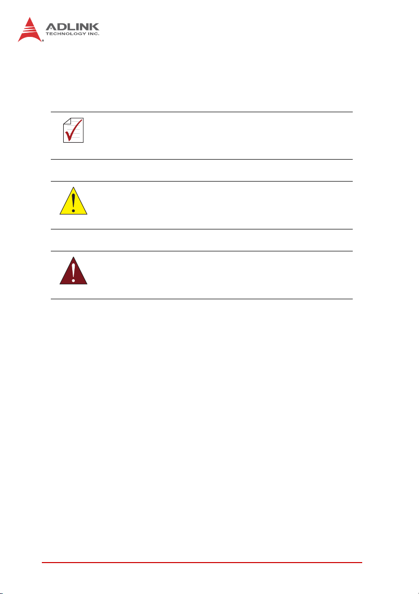
The PCI-8254/58, see Figure 1 below for its system functions,
uses one digital signal processor (DSP) from Texas Instrument
(TI) as its main computing unit and integrates high speed large
volume Field Programmable Gate Array (FPGA) to provide 4/8
independent PID control, high speed encoder output unit, 2/4 high
speed position compare and trigger output, move & general
purposed I/O and logic control. It separates isolation circuit into
exclusive terminal board DIN-825-GP4 to prevent the burning out
of PCI-8254/58 from incorrect wiring. Thanks to full range of
flexing resistant wires from ADLINK, it connects with market
available popular servo drives easily.
Introduction 1
Page 16
FPGA
Flash ROM
DPRAM
SDRAM
PCI Bus
PCI Bus
PCI
Bridge
Misc.
functions
DSP
A/D
circuitry
D/A
circuitry
Encoder
Input
SCSI 100P
EA
EB
EZ
DIN-825-GP4
Isolation
CMP & TRG
4/8 PID Controllers
Motion
I/Os
GPIO
TRG
Output
TTL I/Os
PEL
MEL
ORG
DIO
DSUB 37P
Figure 1-1: PCI-8254/58 system block diagram
Graphical motion control interface – MotionCreatorPro 2 is a
Windows-based motion control software development tool for
motion control and I/O status monitoring. You may employ this
development tool for axis, PID, and feed-forward gain setup as
well as analysis on motion variation curve and data. Embedded
Setup Wizard can guide you throughout the process of hardware
installation and wiring, close circuit PID parameter adjustments
and single axis operation for reduced development time and costs.
The Windows Programming Libraries supports Windows coding
environment including: Visual Studio C++ 6.0, Microsoft .NET
framework based VB.NET and C++, and Borland's C++ Builder.
There are sample programs available in the installation folders.
2Introduction
Page 17

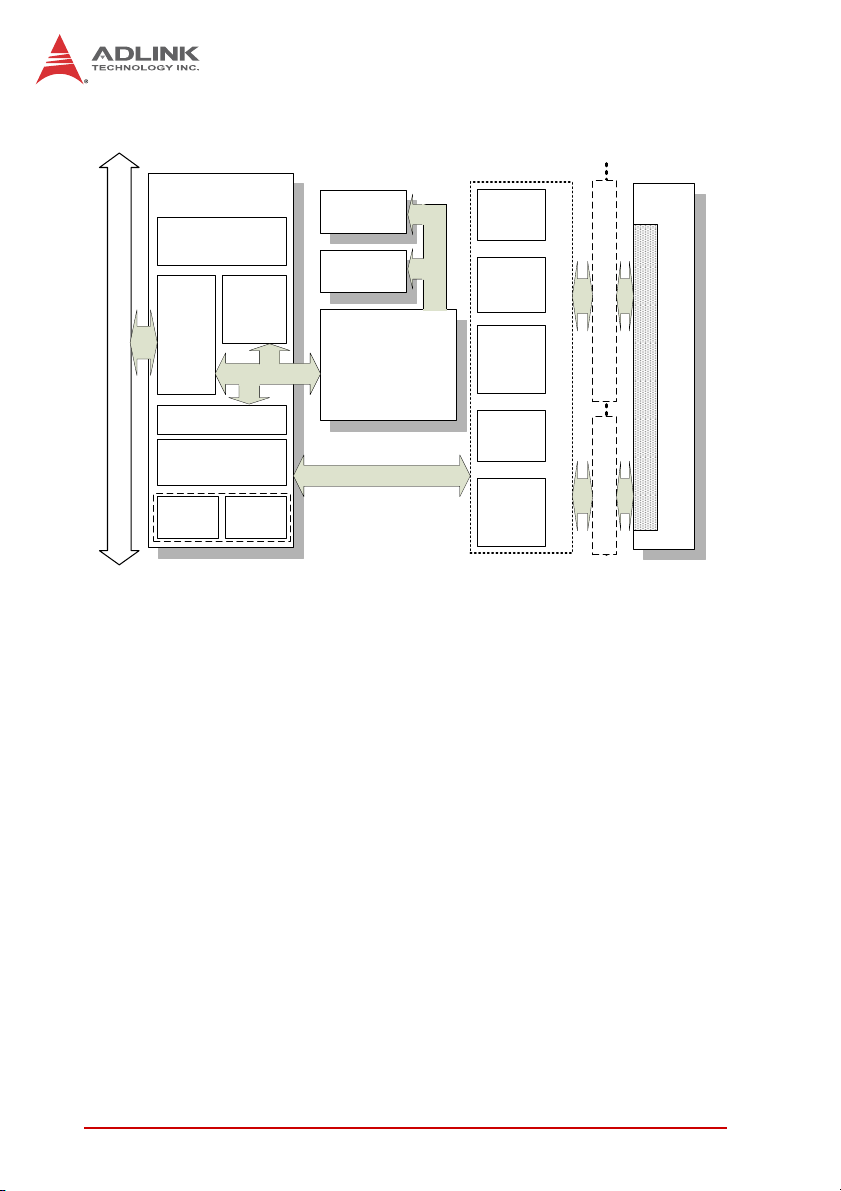
PCI-8254 / PCI-8258
The flow chart below will guide you in using this manual as well as
help you to locate any required information effectively.
Hardware installation
Wiring and jumper setup
Set up card and adjust axis parameters
with MotionCreatorPro 2
Control axis with MotionCreatorPro 2
Develop application with APS library
No
Is the system running
successfully?
Yes
Chapter II and III
MotionCreatorPro 2
User's Manual
Chapter IV
Chapter II and III
MotionCreatorPro 2
User's Manual
APS and ADCNC
library
End
Figure 1-2: System installation flow chart
Introduction 3
Page 18
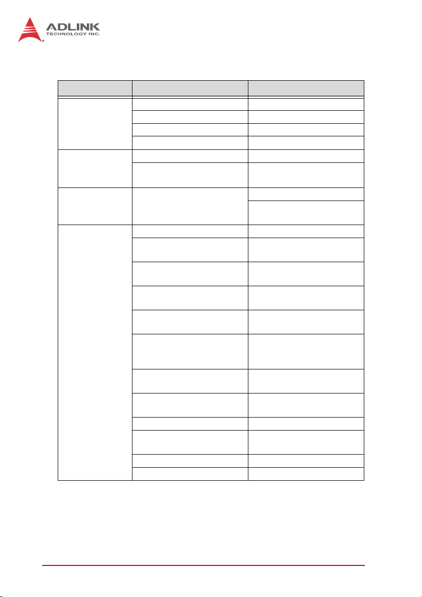
1.1 Product Specifications
Item Description
Bus information PCI Rev. 2.2, 33MHz
System
DSP
Board-to-board
interface
Closed circuit
control
PCI bus width 32-bit
PCI bus voltage 3.3V, 5V
PCI bus IRQ settings Assigned by PCI controller
Model TI 375MHz floating DSP
Memory
(for program and data)
Connector
Number of axes supported 4/8 axes for PCI-8254/8
Analog command output
resolution
Analog command output
interface
Maximum servo update
rate
PID (Kp, Ki and Kd) gain
range
Speed and acceleration
feed-forward (Aff, Vff) gain
range
Position / speed command
range
Acceleration / deceleration
range
Encoder input frequency 20 MHz @ 4x AB
Encoder input mode
Encoder input interface ±12 volts, TTL compatible
Filter
DDR2 SDRAM: 64Mx16bit
Flash ROM: 16M-bit
1x SCSI-II 100P for PCI-8254
1x Dual SCSI VHDCI 100P
for PCI-8258
±10 volts, resolution: 16 bit
Difference / single end
output
50us-500us
(programmable)
0 to 32,767
0 to 32,767
32 bit
32 bit
CW/CCW,
1x/2x/4x AB Phase
Biquad filter & low-pass filter
4Introduction
Page 19

I/O interface
Analog input
Analog output
General
purpose digital
I/O
Motion control
function
PCI-8254 / PCI-8258
Item Description
Motion control relevant I/O
Drive relevant I/O
Max. input channel 4/8, single ended input
Input voltage range ±10 V
Sampling frequency 100 kHz
Resolution 12 bits, no missing codes
Accuracy ±1.5mV for ±10V input
Overload voltage ±15 V
Max. output channel
Output voltage range ±10V
Output current ±50mA (Typ.)
Resolution 16 bits, no missing codes
Accuracy ±1.2mV for ±10V output
Protection circuit
Settling Time 15us, full-scale step
General purpose I/O
Speed Profile Planning
Trajectory Planing
Linear interpolation:
2-6 axes
Home Return
Plus/Minus end limitsignal
Zero-position for each axis
Servo ON
In-position signal /
Zero-Speed detection
Alarm
4/8, difference/single
ended output
Earth short circuit
protection
20/24-CH input & 20/24-CH
TTL output (optical
isolation design for
DIN-825-GP4)
Trapezoidal Curve and
S-Curve
Jogging
Point-to-point movement
Online position/speed
change
3 axes arc interpolation
3 axes spiral interpolation
3 axes helix interpolation
User customizing (see
zero-position, limit switch,
EZ signals for reference)
Introduction 5
Page 20

Industrial
application
Interrupt
Position
comparison
& trigger output
Item Description
Each axis supports 50
points buffer memory
(BUFs)
Supports
Point table
Motion Monitoring
Synchronous move
Master-client axes control
Data sampling
System error diagnostics Watchdog timer
Motion status event/error
alarm/in position/
emergency stop
Pulse output interface Difference output
Trigger channel
Pulse logic
Trigger output frequency
Minimum pulse width 100ns programmable
Position comparison mode
FIFO capacity
point-to-point/line/arc and
spiral interpolation
Supports dwell function
Supports pause/resume
function
Supports DO function
Motion control relevant I/O
monitoring
Motion monitoring
4/8 axes corresponding
PCI-8254/PCI-8258
Up to 4/8 axis (including
ganty control)
Motion speed profile/
motion status/motion
control relevant I/O
Planning in accordance
with the manual
2/4 corresponding
PCI-8254/PCI-8258
Programmable active-high
or active-low
Linear compare trigger:
1MHz
FIFO compare trigger:
255K ~ 1MHz
FIFO and linear
comparison
255 points
(channel independent)
6Introduction
Page 21

Item Description
Maximum number of
channels
PWM control
Program
download
Control modes
Resolution 16 bit
Max. number of
downloadable programs
Program size
Program logic Boolean function, circuit
Mathematical operation Yes
Motion event trigger Yes
Environment Condition
PCI-8254 / PCI-8258
2/4 CH correspondence
PCI-8254/PCI-8258
● Fixed frequency,
variable duty cycle ratio
● Variable frequency,
fixed duty cycle ratio
● Variable frequency,
variable duty cycle ratio
8
1,024 lines for each
program
Item
Working ambient
temperature
Storage ambient
temperature
Working ambient
humidity
Storage ambient
humidity
Noise impedance
Environment
condition
Cooling condition Self-cooling
Power
consumption
Introduction 7
0~55°C
-20~75°C
10~90%RH, without condensation
10~90%RH, without condensation
Noise voltage 1500VPP noise frequency 25~60Hz
using noise simulator
Minimal corrosive gas, dust
+3.3V @ 0.8A typical
+5V @ 0.8A typical
+/-12V @ 0.5A typical
Page 22

1.2 Software Support
1.2.1 Software Support Library
PCI-8254/PCI-8258 supports Windows XP/7 32/64 bit operating
system and provides a complete function library and DLL files for
easy application development by users.
1.2.2 MotionCreatorPro 2
MotionCreatorPro 2 is a user interface exclusively developed for
ADLINK motion control products in common Windows
environment. You may easily set up card and axis parameters with
the help of MotionCreatorPro 2. The Setup Wizard enables users
to complete hardware installation, signal configuration,
close-circuit PID gaining auto tuning and single-axis manipulation
to reduce application development time. MotionCreatorPro 2 not
only effectively reduces your development time but also enables
you to concurrently validate the overall mechanism and electric
design with all its single axis and interpolation motion operation
pages.
1.3 Terminal Board
The PCI-8254/58 exclusive terminal board "DIN-825-GP4" can
connect with several market available servo drives with special
cables including the Mitsubishi) J3A and the Yaskawa Sigma V
series or link with servo or stepper drives of other brands with
single ended open cables. Brands with exclusive cables support
are listed below:
8Introduction
Page 23

PCI-8254 / PCI-8258
Pulse command:
Cable Supported brands
HSL-4XMO-DM Mitsubishi J2S series
4XMO-DM-J3 Mitsubishi J3A series
HSL-4XMO-DP Panasonic A4 and A5 series
HSL-4XMO-DY Yaskawa Sigma V series
4XMO-DA Delta A2 series
4XMO-OPEN General purpose
Table 1-1: Cross-reference table of exclusive cables for pulse servo drive
Analog commands:
Cable Supported brands
ACL-DM-J3 Mitsubishi J3A series
ACL-DY Yaskawa Sigma V series
ACL-DP Panasonic MINAS A5/A4 series
4XMO-OPEN General purpose
Table 1-2: Cross-reference table of exclusive cables for analog servo drive
Introduction 9
Page 24

10 Introduction
Page 25

PCI-8254 / PCI-8258
2 Getting Start with The Installation
This chapter teaches you how to install PCI-8254/PCI-8258
hardware and software as well as its I/O wiring.
• Package Contents
• Hardware Installation
• Software Installation
• I/O Wiring
2.1 Package Contents
In addition to this manual you shall find the following item in the
product package box:
• PCI-8254 or PCI-8258 card X 1
• IDE 44p – DSUB 37p flat cable x 1
• Product warranty card X 1
Should there be any item missed or damaged, please consult with
your dealer immediately. Please keep the product along with items
included in its package for easy replacement or repair.
Getting Start with The Installation 11
Page 26
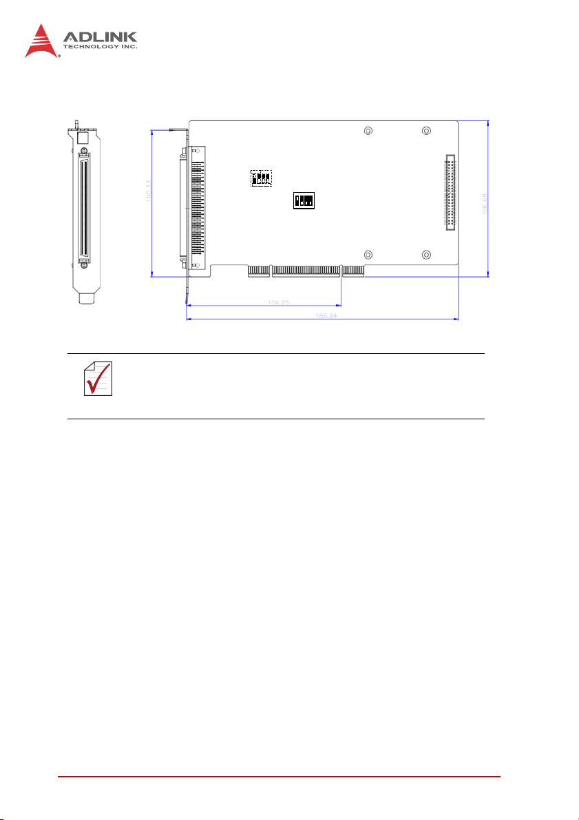
2.2 PCI-8254/PCI-8258 Exterior Profile Diagram
S1
SW2
P1
P2
Dimension in unit of millimeter (mm).
NOTE
NOTE
Figure 2-1: Exterior of your PCI-8254
P1: for Motion control command, Position feedback, and Servo I/O
feedback. (with SCSI 100-PINS connector)
P2: for 16 channel digital TTL input and 16 channel digital TTL
output.
SW2: Card ID setup (0-15)
S1: Analog command mode selection (differential mode /
single-ended mode)
12 Getting Start with The Installation
Page 27
PCI-8254 / PCI-8258
S1
P1
SW2
P2
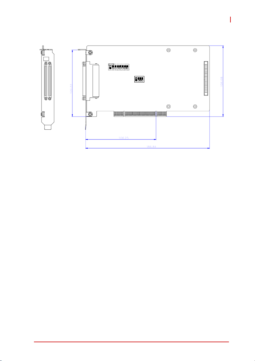
Figure 2-2: Exterior of your PCI-8258
P1: for Motion control command, Position feedback, and Servo I/O
feedback. (with SCSI-VHDCI 200-PINS connector)
P2: for 16 channel digital TTL I/O. (with DSUB 37-PINS
connector)
SW2: Card ID setup (0-15)
S1: Analog command mode selection (differential / single-end
mode)
Getting Start with The Installation 13
Page 28
2.3 Hardware Installation
2.3.1 Hardware Configuration
PCI-8254/58 employs PCI Rev. 2.2 bus. System BIOS can auto
configure memory and IRQ channel.
Exclusive terminal board DIN-825-GP4 provides isolation circuit
and indicator lights for easy connection to varieties of servo drive
and stepper drive.
2.3.2 Installation Procedures
1. Please read this manual carefully and set up signal I/O in
proper mode.
2. Turn off computer power and relevant power on all
terminal boards then connect PCI-8254/58 to 32-bit PCI
slot in your computer. (The slot is usually in white color.)
(Please make sure you have proper ESD (Electrostatic
discharge) protection.)
3. Connect PCI-8254/58 and DIN-825-GP4 with SCSI 100p
cable
4. Set up motion control relevant limit switch on
DIN-825-GP4 board, servo signal and general purpose
digital signal wiring
5. Set up servo or stepper drive connection
6. Turn on system power including computer power,
terminal board relevant powers, and 24Vdc power
7. Verify all I/O signal and servo operation correctness with
MotionCreatorPro 2
Please ground the shielding end of the power terminal to the
earth to reduce risk of electric shock and ensure product
CAUTION
CAUTION
14 Getting Start with The Installation
operation of your electric appliances.
Please disconnect the motor drive from its load before using
the card for the first time to protect your safety. Do not connect
the motor drive to any mechanical devices before the
completion of the installation and fine tuning of the control
system. Connect the system only after the board is adjusted
and the drive parameters can control the motor. Serious
damage may be resulted in otherwise.
Page 29

PCI-8254 / PCI-8258
2.3.3 Troubleshooting
If the computer cannot power on normally or the motion control
system operates abnormally after system installation, please
follow steps described below for troubleshooting. If the problem
persists after you have taken steps described, please consult the
dealer where your product is purchased for technical services.
Abnormalities you encountered Potential causes
Please turn off your computer,
The card does not show up in
Windows Device Manager after its
driver has been installed
MotionCreatorPro2 cannot open
after installing driver in computer
The without signal indicator on
MotionCreatorPro2 lights up after
the motor is connected and the
motor does not work.
When using the MotionCreatorPro2,
all the control indicators of the drive
light correctly but the drive warns
Value of output command differ from
the feedback value from encoder
If motion control, the motor moves
only in one direction rather than back
and forth two way movement
The motor bursts after executing
Servo On command in speed control
operation
The motor makes loud noise after
executing Servo On command in
speed control operation
ensure the card is properly in PCI
slot and the driver is properly
installed by checking its proper
installation in Windows Control
Panel's "Add remove programs"
Ensure .NET framework v3.5 or later
version has been installed in your
system
Please ensure a 24Vdc power is
connected to the terminal board
Please ensure correctness of the
axis parameter setup, alarm logic
(ALM) and the EMG loop
configuration
Please ensure feedback signal
(CW/CCW, 1xAB, 2xAB, 4xAB)
settings comply with that of the drive
Please ensure setting of signal
pattern (CW/CCW, OUT/DIR)
comply with that of the motor drive
Please ensure that the control
direction of encoder and speed
controller comply with each other
Please make sure the actuator is
correctly adjusted and set up, reset
all the "I" and "D" values of PID
parameters, readjust PID gain
Getting Start with The Installation 15
Page 30
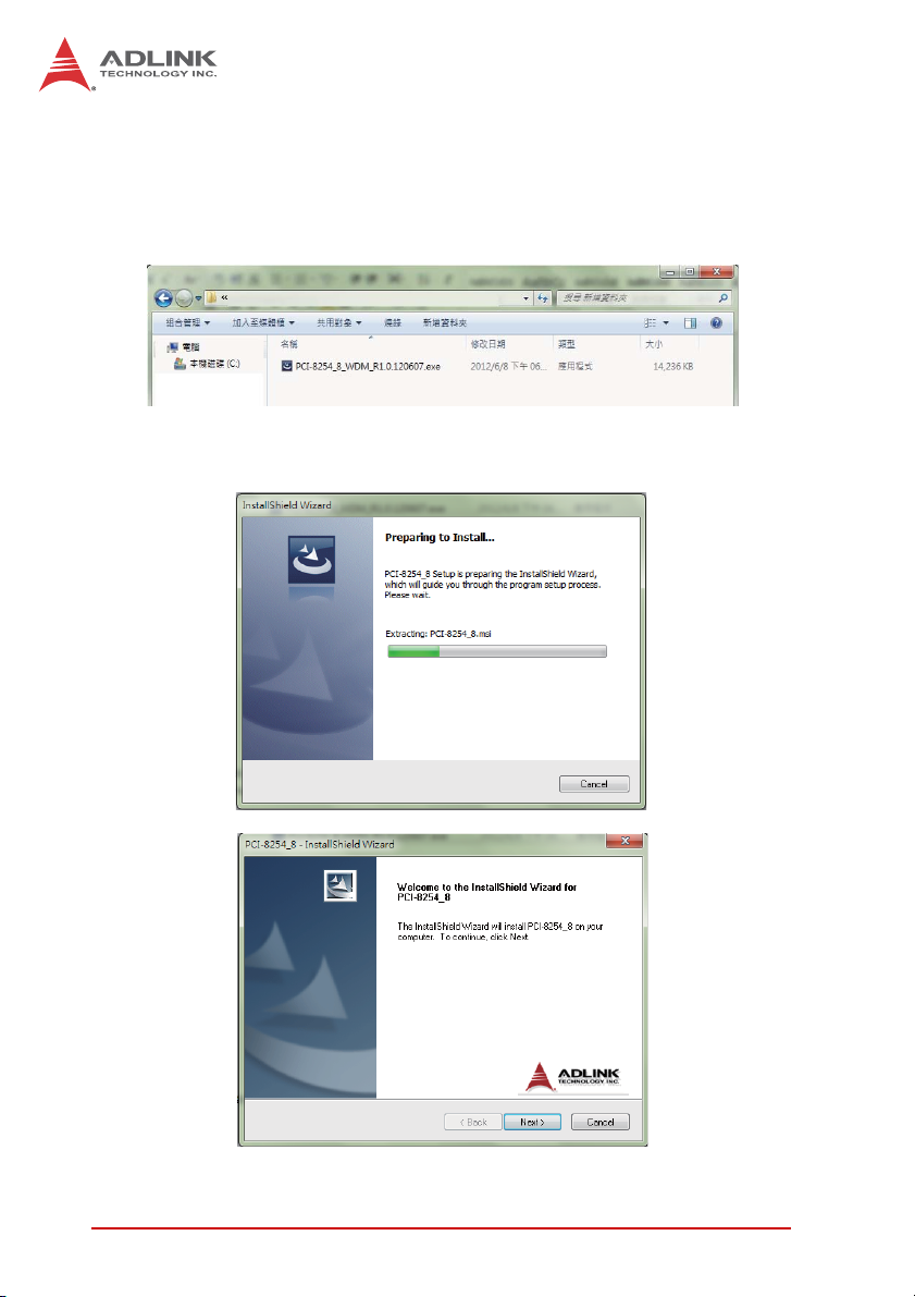
2.4 Software Installation Procedure
Windows driver installation procedure:
Step 1. Execute PCI-8254/PCI-8258 WDM file and run installation
procedure automatically.
Step 2. Click "Next" as prompted to complete the installation
process.
16 Getting Start with The Installation
Page 31

PCI-8254 / PCI-8258
Step 3. Restart your computer after installation is completed.
Step 4. Ensure the Windows Device Manager identify your
PCI-8254/PCI-8258 correctly.
Note: Recommendations: Please download latest installation
software from ADLINK official website to maintain the optimum
operation environment.
(http://www.adlinktech.com/Motion-Control/index.php
)
Getting Start with The Installation 17
Page 32

2.5 Definitions to Key Connector Signal
2.5.1 PCI-8254: Connector
•P1
No. Name I/O Function of Axis No. Name I/O Function of Axis
1 DGND -- Digital ground 51 IEMG | Emergency stop input
2 DGND -- Digital ground 52 Rsv. -- Reserved
3 AGND -- Analog ground 53 AGND -- Analog ground
4 AGND -- Analog ground 54 AGND -- Analog ground
5 AOUT1+ c Analog output (+),(1) 55 AOUT3+ c Analog output (+),(3)
6 AOUT1- c Analog output (-),(1) 56 AOUT3- c Analog output (-),(3)
7 AOUT2+ c Analog output (+),(2) 57 AOUT4+ c Analog output (+),(4)
8 AOUT2- c Analog output (-),(2) 58 AOUT4- c Analog output (-),(4)
9 AIN1 | Analog input, (1) 59 AIN3 | Analog input, (3)
10 AIN2 | Analog input, (2) 60 AIN4 | Analog input, (4)
11 EA5V -- 5V power 61 DGND -- Digital ground
12 EA5V -- 5V power 62 DGND -- Digital ground
13 OUT1+ c Pulse output (+), (1) 63 OUT3+ c Pulse output (+), (3)
14 OUT1- c Pulse output (-), (1) 64 OUT3- c Pulse output (-), (3)
15 DIR1+ c Direction output (+), (1) 65 DIR3+ c Direction output (+), (3)
16 DIR1- c Direction output (-), (1) 66 DIR3- c Direction output (-), (3)
17 OUT2+ c Pulse output (+), (2)
18 OUT2- c Pulse output (-), (2) 68 OUT4- c Pulse output (-), (4)
19 DIR2+ c Direction output (+), (2) 69 DIR4+ c Direction output (+), (4)
20 DIR2- c Direction output (-), (2) 70 DIR4- c Direction output (-), (4)
21 TRG1+ c Trigger output (+), (1) 71 TRG2+ c Trigger output (+), (2)
22 TRG1- c Trigger output (-), (1) 72 TRG2- c Trigger output (-), (2)
23 EA1+ | Encoder A-phase (+),(1) 73 EA3+ | Encoder A-phase (+),(3)
24 EA1- | Encoder A-phase (-),(1) 74 EA3- | Encoder A-phase (-),(3)
25 EB1+ | Encoder B-phase (+),(1) 75 EB3+ | Encoder B-phase (+),(3)
26 EB1- | Encoder B-phase (-),(1) 76 EB3- | Encoder B-phase (-),(3)
67 OUT4+ c Pulse output (+), (4)
18 Getting Start with The Installation
Page 33

PCI-8254 / PCI-8258
No. Name I/O Function of Axis No. Name I/O Function of Axis
27 EZ1+ | Encoder Z-phase (+),(1) 77 EZ3+ | Encoder Z-phase (+),(3)
28 EZ1- | Encoder Z-phase (-),(1) 78 EZ3- | Encoder Z-phase (-),(3)
29 EA2+ | Encoder A-phase (+),(2) 79 EA4+ | Encoder A-phase (+),(4)
30 EA2- | Encoder A-phase (-),(2) 80 EA4- | Encoder A-phase (-),(4)
31 EB2+ | Encoder B-phase (+),(2) 81 EB4+ | Encoder B-phase (+),(4)
32 EB2- | Encoder B-phase (-),(2) 82 EB4- | Encoder B-phase (-),(4)
33 EZ2+ | Encoder Z-phase (+),(2) 83 EZ4+ | Encoder Z-phase (+),(4)
34 EZ2- | Encoder Z-phase (-),(2) 84 EZ4- | Encoder Z-phase (-),(4)
35 ALM1 | Servo alarm,(1) 85 ALM3 | Servo alarm,(3)
36 ORG1 | Origin Signal, (1) 86 ORG3 | Origin Signal, (3)
37 SVON1 c Servo-ON, (1) 87 SVON3 c Servo-ON, (3)
38 PEL1 | Positive limit, (1) 88 PEL3 | Positive limit, (3)
ZSP1 /
39
INP1
40 MEL1 | Negative limit, (1) 90 MEL3 | Negative limit, (3)
41 ALM2 | Servo alarm,(2) 91 ALM4 | Servo alarm,(4)
42 ORG2 | Origin Signal, (2) 92 ORG4 | Origin Signal, (4)
43 SVON2 c Servo-ON, (2) 93 SVON4 c Servo-ON, (4)
44 PEL2 | Positive limit, (2) 94 PEL4 | Positive limit, (4)
ZSP2 /
45
INP2
MEL2 | Negative limit, (2) 96 MEL4 | Negative limit, (4)
46
47 EDO1 c Digital Output, (1) 97 EDO3 c Digital Output, (3)
48 EDI1 | Digital Input, (1) 98 EDI3 | Digital Input, (3)
49 EDO2 c Digital Output, (2) 99 EDO4 c Digital Output, (4)
50 EDI2 | Digital Input, (2) 100 EDI4 | Digital Input, (4)
Zero Speed (1) /
|
In-Position (1)
Zero Speed (2) /
|
In-Position (2)
ZSP3 /
89
INP3
ZSP4 /
95
INP4
Zero Speed (3) /
|
In-Position (3)
Zero Speed (4) /
|
In-Position (4)
Getting Start with The Installation 19
Page 34

2.5.2 PCI-8258: P1-A/B Connector
•P1-A
No. Name I/O Function of Axis No. Name I/O Function of Axis
1 DGND -- Digital ground 51 IEMG | Emergency stop input
2 DGND -- Digital ground 52 Rsv. -- Reserved
3 AGND -- Analog ground 53 AGND -- Analog ground
4 AGND -- Analog ground 54 AGND -- Analog ground
5 AOUT1+ c Analog output (+),(1) 55 AOUT3+ c Analog output (+),(3)
6 AOUT1- c Analog output (-),(1) 56 AOUT3- c Analog output (-),(3)
7 AOUT2+ c Analog output (+),(2) 57 AOUT4+ c Analog output (+),(4)
8 AOUT2- c Analog output (-),(2) 58 AOUT4- c Analog output (-),(4)
9 AIN1 | Analog input, (1) 59 AIN3 | Analog input, (3)
10 AIN2 | Analog input, (2) 60 AIN4 | Analog input, (4)
11 EA5V -- 5V power 61 DGND -- Digital ground
12 EA5V -- 5V power 62 DGND -- Digital ground
13 OUT1+ c Pulse output (+), (1) 63 OUT3+ c Pulse output (+), (3)
14 OUT1- c Pulse output (-), (1) 64 OUT3- c Pulse output (-), (3)
15 DIR1+ c Direction output (+), (1) 65 DIR3+ c Direction output (+), (3)
16 DIR1- c Direction output (-), (1) 66 DIR3- c Direction output (-), (3)
17 OUT2+ c Pulse output (+), (2)
18 OUT2- c Pulse output (-), (2) 68 OUT4- c Pulse output (-), (4)
19 DIR2+ c Direction output (+), (2) 69 DIR4+ c Direction output (+), (4)
20 DIR2- c Direction output (-), (2) 70 DIR4- c Direction output (-), (4)
21 TRG1+ c Trigger output (+), (1) 71 TRG2+ c Trigger output (+), (2)
22 TRG1- c Trigger output (-), (1) 72 TRG2- c Trigger output (-), (2)
23 EA1+ | Encoder A-phase (+),(1) 73 EA3+ | Encoder A-phase (+),(3)
24 EA1- | Encoder A-phase (-),(1) 74 EA3- | Encoder A-phase (-),(3)
25 EB1+ | Encoder B-phase (+),(1) 75 EB3+ | Encoder B-phase (+),(3)
26 EB1- | Encoder B-phase (-),(1) 76 EB3- | Encoder B-phase (-),(3)
27 EZ1+ | Encoder Z-phase (+),(1) 77 EZ3+ | Encoder Z-phase (+),(3)
28 EZ1- | Encoder Z-phase (-),(1) 78 EZ3- | Encoder Z-phase (-),(3)
67 OUT4+ c Pulse output (+), (4)
20 Getting Start with The Installation
Page 35

PCI-8254 / PCI-8258
No. Name I/O Function of Axis No. Name I/O Function of Axis
29 EA2+ | Encoder A-phase (+),(2) 79 EA4+ | Encoder A-phase (+),(4)
30 EA2- | Encoder A-phase (-),(2) 80 EA4- | Encoder A-phase (-),(4)
31 EB2+ | Encoder B-phase (+),(2) 81 EB4+ | Encoder B-phase (+),(4)
32 EB2- | Encoder B-phase (-),(2) 82 EB4- | Encoder B-phase (-),(4)
33 EZ2+ | Encoder Z-phase (+),(2) 83 EZ4+ | Encoder Z-phase (+),(4)
34 EZ2- | Encoder Z-phase (-),(2) 84 EZ4- | Encoder Z-phase (-),(4)
35 ALM1 | Servo alarm,(1) 85 ALM3 | Servo alarm,(3)
36 ORG1 | Origin Signal, (1) 86 ORG3 | Origin Signal, (3)
37 SVON1 c Servo-ON, (1) 87 SVON3 c Servo-ON, (3)
38 PEL1 | Positive limit, (1) 88 PEL3 | Positive limit, (3)
ZSP1 /
39
INP1
40 MEL1 | Negative limit, (1) 90 MEL3 | Negative limit, (3)
41 ALM2 | Servo alarm,(2) 91 ALM4 | Servo alarm,(4)
42 ORG2 | Origin Signal, (2) 92 ORG4 | Origin Signal, (4)
43 SVON2 c Servo-ON, (2) 93 SVON4 c Servo-ON, (4)
44 PEL2 | Positive limit, (2) 94 PEL4 | Positive limit, (4)
ZSP2 /
45
INP2
46 MEL2 | Negative limit, (2) 96 MEL4 | Negative limit, (4)
47 EDO1 c Digital Output, (1) 97
48 EDI1 | Digital Input, (1) 98 EDI3 | Digital Input, (3)
49 EDO2 c Digital Output, (2) 99 EDO4 c Digital Output, (4)
50 EDI2 | Digital Input, (2) 100 EDI4 | Digital Input, (4)
Zero Speed (1) /
|
In-Position (1)
Zero Speed (2) /
|
In-Position (2)
ZSP3 /
89
INP3
ZSP4 /
95
INP4
EDO3 c Digital Output, (3)
Zero Speed (3) /
|
In-Position (3)
Zero Speed (4) /
|
In-Position (4)
•P1-B
No. Name I/O Function of Axis No. Name I/O Function of Axis
1 Rsv. -- Reserved 51 Rsv. -- Reserved
2 Rsv. -- Reserved 52 Rsv. -- Reserved
3 AGND -- Analog ground 53 AGND -- Analog ground
4 AGND -- Analog ground 54 AGND -- Analog ground
5 AOUT5+ O Analog output (+),(5) 55 AOUT7+ O Analog output (+),(7)
Getting Start with The Installation 21
Page 36

No. Name I/O Function of Axis No. Name I/O Function of Axis
6 AOUT5- O Analog output (-),(5) 56 AOUT7- O Analog output (-),(7)
7 AOUT6+ O Analog output (+),(6) 57 AOUT8+ O Analog output (+),(8)
8 AOUT6- O Analog output (-),(6) 58 AOUT8- O Analog output (-),(8)
9 AIN5 I Analog input, (5) 59 AIN7 I Analog input, (7)
10 AIN6 I Analog input, (6) 60 AIN8 I Analog input, (8)
11 Rsv. -- Reserved 61 DGND -- Digital ground
12 Rsv. -- Reserved 62 DGND -- Digital ground
13 OUT5+ O Pulse output (+), (5) 63 OUT7+ O Pulse output (+), (7)
14 OUT5- O Pulse output (-), (5) 64 OUT7- O Pulse output (-), (7)
15 DIR5+ O Direction output (+), (5) 65 DIR7+ O Direction output (+), (7)
16 DIR5- O Direction output (-), (5) 66 DIR7- O Direction output (-), (7)
17 OUT6+ O Pulse output (+), (6) 67 OUT8+ O Pulse output (+), (8)
18 OUT6- O Pulse output (-), (6) 68 OUT8- O Pulse output (-), (8)
19 DIR6+ O Direction output (+), (6) 69 DIR8+ O Direction output (+), (8)
20 DIR6- O Direction output (-), (6) 70 DIR8- O Direction output (-), (8)
21 TRG3+ O Trigger output (+), (3) 71 TRG4+ O Trigger output (+), (4)
22 TRG3- O Trigger output (-), (3) 72 TRG4- O Trigger output (-), (4)
23 EA5+ I
24 EA5- I
25 EB5+ I
26 EB5- I
27 EZ5+ I
28 EZ5- I
29 EA6+ I
30 EA6- I
31 EB6+ I
32 EB6- I
33 EZ6+ I
34 EZ6- I
35 ALM5 I Servo alarm,(5) 85 ALM7 I Servo alarm,(7)
36 ORG5 I Origin Signal, (5) 86 ORG7 I Origin Signal, (7)
Encoder A-phase (+),(5)
Encoder A-phase (-),(5)
Encoder B-phase (+),(5)
Encoder B-phase (-),(5)
Encoder Z-phase (+),(5)
Encoder Z-phase (-),(5)
Encoder A-phase (+),(6)
Encoder A-phase (-),(6)
Encoder B-phase (+),(6)
Encoder B-phase (-),(6)
Encoder Z-phase (+),(6)
Encoder Z-phase (-),(6)
73 EA7+ I Encoder A-phase (+),(7)
74 EA7- I Encoder A-phase (-),(7)
75 EB7+ I Encoder B-phase (+),(7)
76 EB7- I Encoder B-phase (-),(7)
77 EZ7+ I Encoder Z-phase (+),(7)
78 EZ7- I Encoder Z-phase (-),(7)
79 EA8+ I Encoder A-phase (+),(8)
80 EA8- I Encoder A-phase (-),(8)
81 EB8+ I Encoder B-phase (+),(8)
82 EB8- I Encoder B-phase (-),(8)
83 EZ8+ I Encoder Z-phase (+),(8)
84 EZ8- I Encoder Z-phase (-),(8)
22 Getting Start with The Installation
Page 37

PCI-8254 / PCI-8258
No. Name I/O Function of Axis No. Name I/O Function of Axis
37 SVON5 O Servo-ON, (5) 87 SVON7 O Servo-ON, (7)
38 PEL5 I Positive limit, (5) 88 PEL7 I Positive limit, (7)
ZSP5 /
39
INP5
40 MEL5 I Negative limit, (5) 90 MEL7 I Negative limit, (7)
41 ALM6 I Servo alarm,(6) 91 ALM8 I Servo alarm,(8)
42 ORG6 I Origin Signal, (6) 92 ORG8 I Origin Signal, (8)
43 SVON6 O Servo-ON, (6) 93 SVON8 O Servo-ON, (8)
44 PEL6 I Positive limit, (6) 94 PEL8 I Positive limit, (8)
ZSP6 /
45
INP6
46 MEL6 I Negative limit, (6) 96 MEL8 I Negative limit, (8)
47 EDO5 O Digital Output, (5) 97 EDO7 O Digital Output, (7)
48 EDI5 I Digital Input, (5) 98 EDI7 I Digital Input, (7)
49 EDO6 O Digital Output, (6) 99 EDO8 O Digital Output, (8)
50 EDI6 I Digital Input, (6) 100 EDI8 I Digital Input, (8)
Zero Speed (5) /
I
In-Position (5)
Zero Speed (6) /
I
In-Position (6)
ZSP7 /
89
INP7
ZSP8 /
95
INP8
Zero Speed (7) /
I
In-Position (7)
Zero Speed (8) /
I
In-Position (8)
2.5.3 PCI-8254/58: P2 Connector
•P2
No. Name I/O Function of Axis No. Name I/O Function of Axis
1 Rsv. - - Reserved 20 VDD | +5V power supply input
2 TDI1 | TTL input, (1) 21 TDO1 c TTL output, (1)
3 TDI2 | TTL input, (2) 22 TDO2 c TTL output, (2)
4 TDI3 | TTL input, (3) 23 TDO3 c TTL output, (3)
5 TDI4 | TTL input, (4) 24 TDO4 c TTL output, (4)
6 TDI5 | TTL input, (5) 25 TDO5 c TTL output, (5)
7 TDI6 | TTL input, (6) 26 TDO6 c TTL output, (6)
8 TDI7 | TTL input, (7) 27 TDO7 c TTL output, (7)
9 TDI8 | TTL input, (8) 28 TDO8 c TTL output, (8)
10 TDI9 | TTL input, (9) 29 TDO9 c TTL output, (9)
11 TDI10 | TTL input, (10) 30 TDO10 c TTL output, (10)
Getting Start with The Installation 23
Page 38

No. Name I/O Function of Axis No. Name I/O Function of Axis
12 TDI11 | TTL input, (11) 31 TDO11 c TTL output, (11)
13 TDI12 | TTL input, (12) 32 TDO12 c TTL output, (12)
14 TDI13 | TTL input, (13) 33 TDO13 c TTL output, (13)
15 TDI14 | TTL input, (14) 34 TDO14 c TTL output, (14)
16 TDI15 | TTL input, (15) 35 TDO15 c TTL output, (15)
17 TDI16 | TTL input, (16) 36 TDO16 c TTL output, (16)
18 DGND - Digital ground 37 DGND - Digital ground
19 VDD | +5V power supply input -- -- -- --
2.6 DIP Switch
2.6.1 S1: Analog Output Mode Settings
This switch is used for switching analog command output modes
with default settings at differential type output. In general, you
adjust according to individual servo drive interface. The PCI-8254
model uses switches 1-4 only.
differential mode
single-end mode
24 Getting Start with The Installation
Page 39

PCI-8254 / PCI-8258
2.6.2 SW2: Card ID Switch
This switch is used for adjusting card ID for easy identification in
user application programs. Take example. If you set card ID to
”0-0-0-1” (OFF-OFF-OFF-ON) then the card ID is ”1” and the ID
table should be set up as described below:
Card ID Switch Setting (ON=1)
0 0000
1 0001
2 0010
3 0011
4 0100
5 0101
6 0110
7 0 111
8 1000
9 1001
10 1010
11 1011
12 1100
13 1101
14 111 0
15 1111 ( de fault )
Getting Start with The Installation 25
Page 40

2.7 IDE 44p – DSUB 37p Bus
This card include one IDE cable from IDE 44 pin to DSUB 37 pin.
It is used for PCI-8254 / PCI-8258 P2 extension 16 channel digital
input and 16 channel digital output.
26 Getting Start with The Installation
Page 41

PCI-8254 / PCI-8258
2.8 Exclusive Board - DIN-825-GP4
The DIN-825-GP4 terminal board is designed for
PCI-8254/PCI-8258 and AMP-204C/AMP-208C exclusively. It
connects with market available servo drives with special cables
including the Mitsubishi's J3A and the Yaskawa Sigma V series or
other servo or stepper drives with single end open cables.
The DIN-825-GP4 board supports both PCI-8254/PCI-8258
and AMP-204C/AMP-208C. DO NOT connect it to other
CAUTION
ADLINK's motion controller or it may be damaged.
Main connector
(to PCI board)
Brake signal
Motion I/O signals
Analog commands
(Torque Control)
Analog input signals
Power &
EMG signal
Pulse commands
(Position Control)
Additional 16 Digital
output signals
Additional 16 Digital
Laser control signals
Figure 2-3: Exterior of DIN-825-GP4
I/O connector
(to PCI board)
input signals
Getting Start with The Installation 27
Page 42

2.8.1 Definitions to Connector
1. P1: This is one SCSI
100-PINS connector for
motion control signals.
2. CMA1–4: These are four
26-PINS connector for
connecting to servo
drive to do S/T mode
control and analog
CMA1
J4
CMA2
CMA3
CMA4
P1
control commands
output.
3. CMP1–4: These are four
26-PINS connectors for
connecting to servo
drive to do P mode
control or stepper drive
to output pulse control
commands. It may be
CMP1
CMP2
J3
CMP3
CMP4
CN1
S1
S2
J6
connected to Mitsubishi
J3A series, Yaskawa
Sigma II, III & V series,
IOIF2
IOIF3
and Panasonic MINAS
A4&A5 with exclusive
cables.
4. J1–J3: These are three
IOIF1
IOIF4
sets of 10-pins screw
lock connectors
(screwed series, Delta
P2
A2 series, or connection
to other servo or stepper
drives with single end
open cables). It may be
connected to any analog
Figure 2-4: Exterior of DIN-825-GP4
input signal, comparing
trigger signal, plus/minus limit switch and homing signal '.
5. J4: This is one 8-PINS connector for connecting to Brake
Signal.
6. J5: This is one 5-PINS connector for connecting to
terminal board main power and emergency stop signals.
J2 J1
J5
28 Getting Start with The Installation
Page 43

PCI-8254 / PCI-8258
7. J6: This is one 5-PINS connector for connecting to four
isolation digital output channel.
8. P2: This is one DSUB 37-PINS connector for connecting
to 16 channel digital input signal and 16 channel digital
output signal in the controller (TTL).
9. IOIF1-IOIF4: These are four 9-PINS connectors for
connecting to 16 channel digital input signal and 16
channel digital output signal for common uses.
10.Newly added CN1: This is one 9-pin connector for laser
control.
Getting Start with The Installation 29
Page 44

2.8.2 Connector: For Connecting to PCI-8254/PCI-8258/AMP-204C/AMP-208C
•P1:
No. Name I/O Function of Axis No. Name I/O Function of Axis
1 DGND -- Digital ground 51 IEMG | Emergency stop input
2 DGND -- Digital ground 52 Rsv. -- Reserved
3 AGND -- Analog ground 53 AGND -- Analog ground
4 AGND -- Analog ground 54 AGND -- Analog ground
5 AOUT1+ c Analog output (+),(1) 55 AOUT3+ c Analog output (+),(3)
6 AOUT1- c Analog output (-),(1) 56 AOUT3- c Analog output (-),(3)
7 AOUT2+ c Analog output (+),(2) 57 AOUT4+ c Analog output (+),(4)
8 AOUT2- c Analog output (-),(2) 58 AOUT4- c Analog output (-),(4)
9 AIN1 | Analog input, (1) 59 AIN3 | Analog input, (3)
10 AIN2 | Analog input, (2) 60 AIN4 | Analog input, (4)
11 Rsv. -- Reserved 61 DGND -- Digital ground
12 Rsv. -- Reserved 62 DGND -- Digital ground
13 OUT1+ c Pulse output (+), (1) 63 OUT3+ c Pulse output (+), (3)
14 OUT1- c Pulse output (-), (1) 64 OUT3- c Pulse output (-), (3)
15 DIR1+ c Direction output (+), (1) 65 DIR3+ c Direction output (+), (3)
16 DIR1- c Direction output (-), (1) 66 DIR3- c Direction output (-), (3)
17 OUT2+ c Pulse output (+), (2)
18 OUT2- c Pulse output (-), (2) 68 OUT4- c Pulse output (-), (4)
19 DIR2+ c Direction output (+), (2) 69 DIR4+ c Direction output (+), (4)
20 DIR2- c Direction output (-), (2) 70 DIR4- c Direction output (-), (4)
21 TRG1+ c Trigger output (+), (1) 71 TRG2+ c Trigger output (+), (2)
22 TRG1- c Trigger output (-), (1) 72 TRG2- c Trigger output (-), (2)
23 EA1+ | Encoder A-phase (+),(1) 73 EA3+ | Encoder A-phase (+),(3)
24 EA1- | Encoder A-phase (-),(1) 74 EA3- | Encoder A-phase (-),(3)
25 EB1+ | Encoder B-phase (+),(1) 75 EB3+ | Encoder B-phase (+),(3)
26 EB1- | Encoder B-phase (-),(1) 76 EB3- | Encoder B-phase (-),(3)
67 OUT4+ c Pulse output (+), (4)
30 Getting Start with The Installation
Page 45

PCI-8254 / PCI-8258
No. Name I/O Function of Axis No. Name I/O Function of Axis
27 EZ1+ | Encoder Z-phase (+),(1) 77 EZ3+ | Encoder Z-phase (+),(3)
28 EZ1- | Encoder Z-phase (-),(1) 78 EZ3- | Encoder Z-phase (-),(3)
29 EA2+ | Encoder A-phase (+),(2) 79 EA4+ | Encoder A-phase (+),(4)
30 EA2- | Encoder A-phase (-),(2) 80 EA4- | Encoder A-phase (-),(4)
31 EB2+ | Encoder B-phase (+),(2) 81 EB4+ | Encoder B-phase (+),(4)
32 EB2- | Encoder B-phase (-),(2) 82 EB4- | Encoder B-phase (-),(4)
33 EZ2+ | Encoder Z-phase (+),(2) 83 EZ4+ | Encoder Z-phase (+),(4)
34 EZ2- | Encoder Z-phase (-),(2) 84 EZ4- | Encoder Z-phase (-),(4)
35 ALM1 | Servo alarm,(1) 85 ALM3 | Servo alarm,(3)
36 ORG1 | Origin Signal, (1) 86 ORG3 | Origin Signal, (3)
37 SVON1 c Servo-ON, (1) 87 SVON3 c Servo-ON, (3)
38 PEL1 | Positive limit, (1) 88 PEL3 | Positive limit, (3)
ZSP1 /
39
INP1
40 MEL1 | Negative limit, (1) 90 MEL3 | Negative limit, (3)
41 ALM2 | Servo alarm,(2) 91 ALM4 | Servo alarm,(4)
42 ORG2 | Origin Signal, (2) 92 ORG4 | Origin Signal, (4)
43 SVON2 c Servo-ON, (2) 93 SVON4 c Servo-ON, (4)
44 PEL2 | Positive limit, (2) 94 PEL4 | Positive limit, (4)
ZSP2 /
45
INP2
MEL2 | Negative limit, (2) 96 MEL4 | Negative limit, (4)
46
47 EDO1 c Digital Output, (1) 97 EDO3 c Digital Output, (3)
48 EDI1 | Digital Input, (1) 98 EDI3 | Digital Input, (3)
49 EDO2 c Digital Output, (2) 99 EDO4 c Digital Output, (4)
50 EDI2 | Digital Input, (2) 100 EDI4 | Digital Input, (4)
Zero Speed (1) /
|
In-Position (1)
Zero Speed (2) /
|
In-Position (2)
ZSP3 /
89
INP3
ZSP4 /
95
INP4
Zero Speed (3) /
|
In-Position (3)
Zero Speed (4) /
|
In-Position (4)
•P2:
No. Name I/O Function of Axis No. Name I/O Function of Axis
1 Rsv. - - Reserved 20 VDD c +5V power supply output
2 TDI1 | TTL input, (1) 21 TDO1 c TTL output, (1)
Getting Start with The Installation 31
Page 46

No. Name I/O Function of Axis No. Name I/O Function of Axis
3 TDI2 | TTL input, (2) 22 TDO2 c TTL output, (2)
4 TDI3 | TTL input, (3) 23 TDO3 c TTL output, (3)
5 TDI4 | TTL input, (4) 24 TDO4 c TTL output, (4)
6 TDI5 | TTL input, (5) 25 TDO5 c TTL output, (5)
7 TDI6 | TTL input, (6) 26 TDO6 c TTL output, (6)
8 TDI7 | TTL input, (7) 27 TDO7 c TTL output, (7)
9 TDI8 | TTL input, (8) 28 TDO8 c TTL output, (8)
10 TDI9 | TTL input, (9) 29 TDO9 c TTL output, (9)
11 TDI10 | TTL input, (10) 30 TDO10 c TTL output, (10)
12 TDI11 | TTL input, (11) 31 TDO11 c TTL output, (11)
13 TDI12 | TTL input, (12) 32 TDO12 c TTL output, (12)
14 TDI13 | TTL input, (13) 33 TDO13 c TTL output, (13)
15 TDI14 | TTL input, (14) 34 TDO14 c TTL output, (14)
16 TDI15 | TTL input, (15) 35 TDO15 c TTL output, (15)
17 TDI16 | TTL input, (16) 36 TDO16 c TTL output, (16)
18 EGND - External power ground 37 EGND - External power ground
19 VDD | +5V power supply input -- -- -- --
•J1:
No. Name I/O Function of Axis No. Name I/O Function of Axis
1 DICOM -- Digital input common 6 EDI4 | Isolated digital input, (4)
2 EDI3 | Isolated digital input, (3) 7 PEL4 | Positive limit, (4)
3 PEL3 | Positive limit, (3) 8 ORG4 | Origin Signal, (4)
4 ORG3 | Origin Signal, (3) 9 MEL4 | Negative limit, (4)
5 MEL3 | Negative limit, (3) 10 DOCOM -- Digital output common
32 Getting Start with The Installation
Page 47

PCI-8254 / PCI-8258
•J2:
No. Name I/O Function of Axis No. Name I/O Function of Axis
1 DICOM -- Digital input common 6 EDI2 | Isolated digital input, (2)
2 EDI1 | Isolated digital input, (1) 7 PEL2 | Positive limit, (2)
3 PEL1 | Positive limit, (1) 8 ORG2 | Origin Signal, (2)
4 ORG1 | Origin Signal, (1) 9 MEL2 | Negative limit, (2)
5 MEL1 | Negative limit, (1) 10 DOCOM -- Digital output common
1. Please connect DICOM to external power supply
(24VDC in general) if possible.
NOTE
NOTE
2. Please connect DOCOM to ground (GND) of
external power supply if possible.
•J3:
No. Name I/O Function of Axis No. Name I/O Function of Axis
1 DGND -- Isolated digital ground 6 AGND -- Analog ground
2 TRG2- c Trigger output (-), (2) 7 AI4 | Analog input, (4)
3 TRG2+ c Trigger output (+), (2) 8 AI3 | Analog input, (3)
4 TRG1- c Trigger output (-), (1) 9 AI2 | Analog input, (2)
5 TG1+ c Trigger output (+), (1) 10 AI1 | Analog input, (1)
• J4: Brake Connector
No. Name I/O Function of Axis No. Name I/O Function of Axis
BRAKE 1+
1
BRAKE 1-
2
BRAKE 2+
3
BRAKE 2-
4
Getting Start with The Installation 33
-- Brake signal (+), (1) 6
| Brake signal (-), (1) 7
| Brake signal (+), (2) 8
| Brake signal (-), (2) 9
BRAKE 3+
BRAKE 3-
BRAKE 4+
BRAKE 4-
| Brake signal (+), (3)
| Brake signal (-), (3)
| Brake signal (+), (4)
| Brake signal (-), (4)
Page 48
•J5
No. Name I/O Function of Axis No. Name I/O Function of Axis
1 I24V -- Ext. power supply, +24V 4 DOCOM -- Digital output common
2 IGND -- Ext. power ground 5
3 DICOM -- Digital input common 6 -- -- --
EEMG
| Ext. Emergency signal
1. Please connect DICOM to external power supply
(24VDC in general) if possible.
NOTE
NOTE
2. Please connect DOCOM to ground (GND) of
external power supply if possible.
•J6
No. Name I/O Function of Axis No. Name I/O Function of Axis
1 EDO1 c Digital output, (1) 4 EDO4 c Digital output, (4)
2 EDO2 c Digital output, (2) 5 DOCOM c Digital output common
3 EDO3 c Digital output, (3) 6 -- c --
•IOIF1:
No. Name I/O Function of Axis No. Name I/O Function of Axis
1 DI1 I
2 DI2 I
3 DI3 I
4 DI4 I
5 DI5 I
Additional isolated digital
input, (1)
Additional isolated digital
input, (2)
Additional isolated digital
input, (3)
Additional isolated digital
input, (4)
Additional isolated digital
input, (5)
6 DI6 I
7 DI7 I
8 DI8 I
9 DICOM -- Digital input common
-- -- -- --
34 Getting Start with The Installation
Additional isolated digital
input, (6)
Additional isolated digital
input, (7)
Additional isolated digital
input, (8)
Page 49

PCI-8254 / PCI-8258
•IOIF2:
No. Name I/O Function of Axis No. Name I/O Function of Axis
1 DI9 I
2 DI10 I
3 DI11 I
4 DI12 I
5 DI13 I
Additional isolated digital
input, (9)
Additional isolated digital
input, (10)
Additional isolated digital
input, (11)
Additional isolated digital
input, (12)
Additional isolated digital
input, (13)
6 DI14 I
7 DI15 I
8 DI1 I
9 DICOM -- Digital input common
-- -- -- --
Additional isolated digital
input, (14)
Additional isolated digital
input, (15)
Additional isolated digital
input, (16)
•IOIF3:
No. Name I/O Function of Axis No. Name I/O Function of Axis
※DO1
1
※DO2
2
3 ※DO3 O
※DO4
4
5 ※DO5 O
Additional isolated digital
O
output, (1)
Additional isolated digital
O
output, (2)
Additional isolated digital
output, (3)
Additional isolated digital
O
output, (4)
Additional isolated digital
output, (5)
6 DO6 O
7 DO7 O
8 DO8 O
9 DOCOM -- Digital output common
-- -- -- --
Additional isolated digital
output, (6)
Additional isolated digital
output, (7)
Additional isolated digital
output, (8)
※ The digital output current may reach 250mA
NOTE
NOTE
Getting Start with The Installation 35
Page 50

•IOIF4:
No. Name I/O Function of Axis No. Name I/O Function of Axis
1 DO9 O
2 DO10 O
3 DO11 O
4 DO12 O
5 DO13 O
Additional isolated digital
output, (9)
Additional isolated digital
output, (10)
Additional isolated digital
output, (11)
Additional isolated digital
output, (12)
Additional isolated digital
output, (13)
6 DO14 O
7 DO15 O
8 DO16 O
9 DOCOM --
-- -- --
Additional isolated digital
output, (14)
Additional isolated digital
output, (15)
Additional isolated digital
output, (16)
Digital output common
--
1. Please connect DICOM to external power supply
(24VDC in general) if possible.
NOTE
NOTE
2. Please connect DOCOM to ground (GND) of
external power supply if possible.
• CN1:
No. Name I/O Function of Axis No. Name I/O Function of Axis
1 EDO4 O
2 TG1+ O
3 TG2+ O
4 AOUT4+ O
5 AGND --
Digital output (4)
Trigger output (+), (1)
Trigger output (+), (2)
Analog command output
(+), (4)
Analog ground
6 EDO4- O
7 TG1- O
8 TG2- O
9 DGND --
Digital output (-), (4)
Trigger output (-), (1)
Trigger output (-), (2)
Digital ground
36 Getting Start with The Installation
Page 51

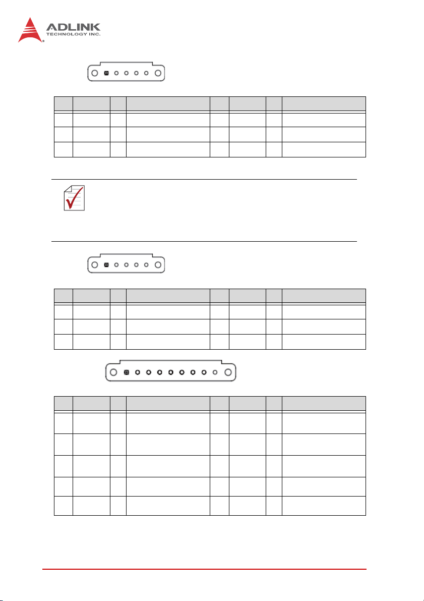
• CMA1~CMA4:
PCI-8254 / PCI-8258
outputsignal
Resetdriversignal/Digital
O
DO
ALM_RST/
10
11 ALM I Servoalarmsignal
12 I24VͲͲExt.powersupply,+24V
13 IGNDͲͲ Ext.powerground
14 BRAKEͲ OBrakesignal(Ͳ)
15 AGNDͲͲ Analogground
16 EBͲ I EncoderBͲphase(Ͳ)
1 SVON O ServoOnsignal19 EMG I Emergencysignal
2 ZSP I Zerospeedsignal20 IGND ͲͲ Ext.powerground
3 Rsv. ͲͲ Reserved21 IGND ͲͲ Ext.powerground
4 Rsv. ͲͲ Reserved.22 IGND ͲͲ Ext.powerground
5 AOUTͲ O Analogcommandoutput(Ͳ)23 Rsv. ͲͲ Reserved
No. Name I/O Function No. Name I/O Function No. Name I/O Function
6 AOUT+ O Analogcommandoutput(+)24 Rsv. ͲͲ Reserved
17 EB+ I EncoderBͲphase(+)
18 AGNDͲͲ Analogground
7 EAͲ I EncoderAͲphase(Ͳ)25 EZͲ I EncoderZͲphase(Ͳ)
8 EA+ I EncoderAͲphase(+)26 EZ+ I EncoderZͲphase(+)
9 BRAKE+ O Brakesignal(+)
ALM_RST / DO: This signal may be selected as general
purpose digital output signal (EDO) or alarm clearance function
NOTE
NOTE
(ALM_RST) by switch S1 or S2.
Getting Start with The Installation 37
Page 52

•CMP1~CMP4:
outputsignal
Resetdriversignal/Digital
O
DO
ALM_RST/
10
11 ALM I Servoalarmsignal
12 I24VͲͲExt.powersupply,+24V
13 IGNDͲͲ Ext.powerground
14 BRAKEͲ OBrakesignal(Ͳ)
15 IGNDͲͲ Ext.powerground
1 SVON O ServoOnsignal19 EMG I Emergencysignal
2 INP I InͲpositionsignal20 IGN D ͲͲ Ext.powerground
3 ERC O Dev.ctr,clr.signal21 IGND ͲͲ Ext.powerground
4 RDY I Servoreadysignal22 IGND ͲͲ Ext.powerground
No. Name I/O Function No. Name I/O Function No. Name I/O Function
5 OUTͲ O Pulsesignal(Ͳ)23 DIRͲ O Dir.Signal(Ͳ)
16 EBͲ I EncoderBͲphase(Ͳ)
17 EB+ I EncoderBͲphase(+)
18 IGNDͲͲ Ext.powerground
6 OUT+ O Pulsesignal(+)24 DIR+ O Dir.Signal(+)
7 EAͲ I EncoderAͲphase(Ͳ)25 EZͲ I EncoderZͲphase(Ͳ)
8 EA+ I EncoderAͲphase(+)26 EZ+ I EncoderZͲphase(+)
9 BRAKE+ O Brakesignal(+)
ALM_RST / DO: You may set this signal to general purpose
digital output signal (EDO) or alarm clearance function
NOTE
NOTE
(ALM_RST) by switch S1 or S2.
38 Getting Start with The Installation
Page 53

PCI-8254 / PCI-8258
2.8.3 S1, S2: EDO/ALM_RST Selection Switch
DIN-825-GP4 is equipped with 4 servo drive reset signals. You
may set up CMA1~CMA4 PIN 10 and CMP1~CMP4 PIN 10 for
servo drive rest or J6 connector DO.1~DO.4 by switch S1 and S2.
Getting Start with The Installation 39
Page 54

40 Getting Start with The Installation
Page 55

PCI-8254 / PCI-8258
3 Signal Connection
PCI-8254/PCI-8258 must connect to servo or stepper motor drive
with exclusive terminal board DIN-825-GP4. All optical isolation
circuit of mechanical relevant I/O and servo relevant I/O are set to
DIN-825-GP4 to prevent damages to primary controller
PCI-8254/PCI-8258 from any invalid signal connection to it. This
may effectively reduce difficulties and times required in replacing
controller relevant products when doing customer service
maintenance tasks. See sections below for detailed descriptions
on precautions required to connect to various mechanical I/O and
servo I/O signals. Contents:
Section 3.1: Analog Command Signal
Section 3.2: Pulse Command Signal
Section 3.3: Encoder Input Signal
Section 3.4: Emergency Stop Signal
Section 3.5: Mechanical Limit Switch Signal
Section 3.6: Original Position Switch Signal
Section 3.7: In-position/Zero Speed Signal
Section 3.8: Servo Alarm Signal
Section 3.9: Servo On Signal
Section 3.10: Analog Input Signal
Section 3.11: Comparing Trigger Signal
Section 3.12: General Purpose Digital Input and Output Signal
Signal Connection 41
Page 56

3.1 Analog Control Command Signal
3.1.1 Single-ended Type Signal: AOUT+
PCI-8254/PCI-8258 provides 4/8 analog control command
channels respectively. Each analog command supports 16-bit
resolution and provides ±10V output range at accuracy smaller
than ± 1mV. Each analog control command can be set to single
ended or differential output mode by adjusting switch S1 to be
used by market available Japanese/Taiwanese and American/EU
servo motor drives. In general, a servo drive can be set to P/S/T
(position/speed/torque) mode. When control mode is set to S/T the
positioning function can be exercised by controlling motor speed
or torque with analog commands. When servo drive is set to P
mode, then pulse command of PCI-8254/PCI-8258 will be used for
open-loop control (see Section 3.2). This analog channel is then
defined as general purpose output one.
See below for corresponding pins of analog command output to
DIN-825-GP4:
CMAx Pin No
(x=1~4)
6 AOUT+ Analog Out Signal, (+) (n) 1~8
NOTE
NOTE
Signal Name
PCI-8258 need two DIN-825-GP4 for eight axes motion control
functions
# 1 controls axes 1 ~ 4 and #2 controls axes 5 ~ 8
Description
(n=1~8)
Axis #
3.1.2 Single-ended Type Signal: AOUT+, AOUT-
4/8 analog control commands of PCI-8254/PCI-8258 can be set to
single ended or differential output mode by adjusting switch S1 to
be used by market available Japanese/Taiwanese and
American/EU servo motor drives. See below for corresponding
pins of analog command output pins against differential analog
signals to DIN-825-GP4:
42 Signal Connection
Page 57

PCI-8254 / PCI-8258
CMAx Pin No
(x=1~4)
6 AOUT+ Analog Out Signal, (+) (n) 1~8
5 AOUT- Analog Out Signal, (-) (n) 1~8
Signal Name
Description
(n=1~8)
PCI-8258 need two DIN-825-GP4 for eight axes motion control
functions
NOTE
NOTE
# 1 controls axes 1 ~ 4 and #2 controls axes 5 ~ 8
• Signal connection template diagram:
Axis #
Figure 3-1: Connection example of differential analog output signal
Signal Connection 43
Page 58

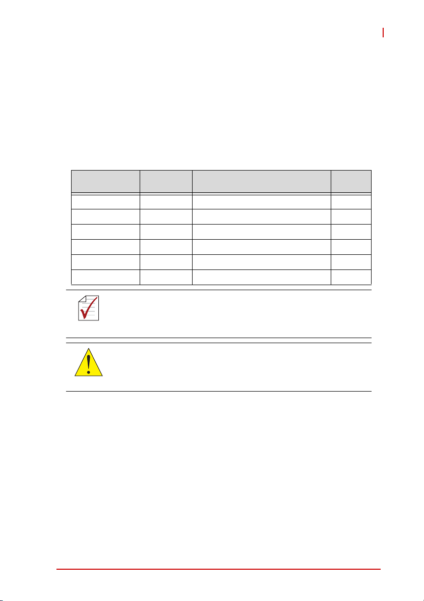
3.2 Pulse Command
In addition to the analog command outputs described in Section
3.1, PCI-8254/PCI-8258 provides 4/8 pulse control command
channel. Each pulse control command can support up to 6.5MHZ
output frequency.
In general, a servo drive can be set to P/S/T (position/speed/
torque) mode. When control mode is set to P mode, then the pulse
command control of PCI-8254/PCI-8258 will be used for
open-loop control.
In addition to servo drive, the Stepper drive also employs pulse
command interface as the primary control input commands. See
below for corresponding pins of pulse command output against
differential pulse signals to DIN-825-GP4:
CMAx Pin No
(x=1~4)
6 OUT+ Pulse signal, (+) (n) 1~8
5 OUT- Pulse signal, (-) (n) 1~8
24 DIR+ Dir. Signal, (+) (n) 1~8
23 DIR- Dir. Signal, (-) (n) 1~8
Signal Name
Description
(n=1~8)
PCI-8258 need two DIN-825-GP4 for eight axes
motion control functions
NOTE
NOTE
# 1 controls axes 1 ~ 4 and #2 controls axes 5 ~ 8
Axis #
44 Signal Connection
Page 59
PCI-8254 / PCI-8258
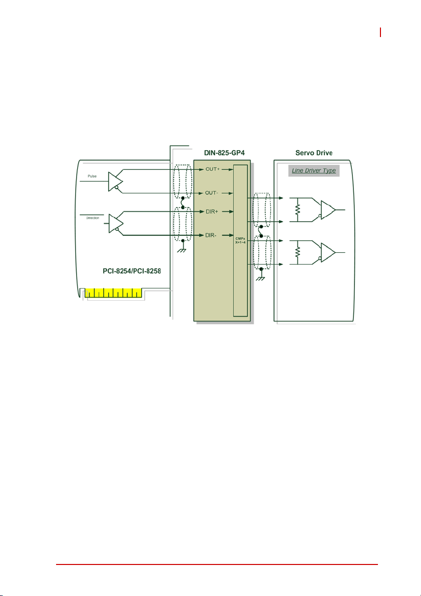
Either servo motor drive or stepper motor drive employs one of the
two input interfaces described below:
1. Line Driver input interface provides better anti noise-resistant
and longer wiring length.
• Signal connection diagram:
Figure 3-2: Line Driver type pulse control command signal connection
example
2. Open-Collector input interface can increase passing
current capacity of signal by adjusting pull-up resistance
value at the shorter wiring length.
Signal Connection 45
Page 60

• Signal connection diagram:
Figure 3-3: Open-Collector type pulse control command signal connection
example
To avoid damages to Line Driver components on controller
caused by invalid wiring please connect the OUT-, DIR- pins of
CAUTION
controller to OUT, DIR pins of motor drive.
The controller employs Line Driver component -26LS31 with
maximum Sink Current at 20mA. Do not use it at current above
CAUTION
this value, the component may be damaged otherwise.
46 Signal Connection
Page 61
PCI-8254 / PCI-8258
3.3 Encoder Input, EA & EB & EZ
PCI-8254/PCI-8258 provides 4/8 encoder input channels
respectively which accept single end input frequency up to 5MHz
with each channel containing EA, EB, and EZ signal. Each group
of EA, EB, and EZ signal contains a pair of differential signal, e.g.
the EA signal contains EA+ and EA-. See Section 4.1.1.4 for how
to use the encoder. See below for corresponding pins of encoder
input on DIN-825-GP4
CMAx Pin No
(x=1~4)
8 EA+ Encoder A-phase (+),(n) 1~8
7 EA- Encoder A-phase (-),(n) 1~8
17 EB+ Encoder B-phase (+),(n) 1~8
16 EB- Encoder B-phase (-),(n) 1~8
26 EZ+ Encoder Z-phase (+),(n) 1~8
25 EZ- Encoder Z-phase (-),(n) 1~8
Signal Name
Description
(n=1~8)
PCI-8258 need two DIN-825-GP4 for eight axes motion control
functions
NOTE
NOTE
# 1 controls axes 1 ~ 4 and #2 controls axes 5 ~ 8
The controller employs Line Receiver component -26LS32 with
maximum Sink Current at 20mA@5V. Do not use it at current
CAUTION
above this value, the component may be damaged otherwise.
Axis #
Signal Connection 47
Page 62

• Signal connection diagram:
Figure 3-4: Line driver type encoder input signal connection example
48 Signal Connection
Page 63

PCI-8254 / PCI-8258
3.4 Emergency Stop Input
PCI-8254/PCI-8258 provides one hardware input emergency stop
signal (EMG). If the external emergency stop signal is triggered, all
motion control commands will be stopped immediately. In addition, the
DIN-825-GP4 is designed to transmit external emergency stop signal
to servo/stepper motor drive to stop operation of every motor
immediately. See below for corresponding pins of emergency stop
signal input on DIN-825-GP4
J5 Pin No Signal Name Description Axis #
5 EEMG
:
External emergency stop input
(external input)
-
CMPx / CMAx
Pin No (x=1~4)
19 EMG(n) Emergency stop (output to drive) 1~8
Signal Name
(n=1~8)
Description Axis #
PCI-8258 need two DIN-825-GP4 for eight axes motion control
functions
NOTE
NOTE
# 1 controls axes 1 ~ 4 and #2 controls axes 5 ~ 8
• Signal connection diagram:
EEMG
J5
EMG
CMPx /
CMAx
x=1~4
IEMG
PCI-8254/PCI-8258
DIN-825-GP4
P1
PS2805
DGND
DICOM
Servo Drive
Figure 3-5: Emergency stop signal connection example
Signal Connection 49
Page 64

3.5 PEL/MEL Input
PCI-8254/PCI-8258 provides 4/8 End-limited switch input
channels. The Plus Limited Switch (PEL) is used as the
mechanical protection switch for movement in the positive
direction. When this switch is triggered, the PCI-8254/PCI-8258
stops its positive direction movement immediately. The Minus
Limited Switch (MEL) is used as the mechanical protection switch
for movement in the negative direction. When this switch is
triggered, the PCI-8254/PCI-8258 stops its negative direction
movement immediately. See below for corresponding pins of
mechanical limit switch signal input on DIN-825-GP4:
J1/J2 Pin No Signal Name Description Axis #
3 PEL(3) / PEL(1) Plus limit switch input (3) / (1) 3 / 1
7 PEL(4) / PEL(2) Plus limit switch input (4) / (2) 4 / 2
5 MEL(3) / MEL(1) Minus limit switch input (3) / (1) 3 / 1
9 MEL(4) / MEL(2) Minus limit switch input (4) / (2) 4 / 2
PCI-8258 need two DIN-825-GP4 for eight axes motion control
functions
NOTE
NOTE
# 1 controls axes 1 ~ 4 and #2 controls axes 5 ~ 8
50 Signal Connection
Page 65

• Signal connection diagram:
PCI-8254 / PCI-8258
Figure 3-6: Mechanical limit switch signal connection example
Signal Connection 51
Page 66

3.6 ORG Input
PCI-8254/PCI-8258 provides 4/8 original position switch input
channels. Working together with the home movement described in
Section 4.3, this function returns the body to its original position
(also known as the zero position). See below for corresponding
pins of original position switch signal input on DIN-825-GP4:
J1/J2 Pin No Signal Name Description Axis #
4 ORG(3) / ORG(1) Original position switch input (3) / (1) 3 / 1
8 ORG(4) / ORG(2) Original position switch input (4) / (2) 4 / 2
PCI-8258 need two DIN-825-GP4 for eight axes motion control
functions
NOTE
NOTE
• Signal connection diagram:
# 1 controls axes 1 ~ 4 and #2 controls axes 5 ~ 8
Figure 3-7: Original position switch signal connection example
52 Signal Connection
Page 67

PCI-8254 / PCI-8258
3.7 INP / ZSP Input
PCI-8254/PCI-8258 provides 4/8 In-position (INP) or zero speed
detection (Zero-speed (ZSP)) input channel. Working with function
described in Section 4.8, it can be used as the trigger source for
in-position events of individual motion. In general, when servo
drive is set to position mode (P mode), the servo issues a (INP)
pulse signal to controller when movement get into position. When
servo drive is set at speed/torque (S/T mode), the actuator sends
a (ZSP) pulse signal to controller when motor speed is zero. See
below for corresponding pins of in-position or zero speed detection
signal input on DIN-825-GP4:
CMAx
Pin No (x=1~4)
2 ZSP(n) Zero speed detection signal 1~4
2INP(n)
Signal Name
(n=1~4)
Description Axis #
In-position Input
(for pulse output mode only)
PCI-8258 need two DIN-825-GP4 for eight axes motion control
functions
NOTE
NOTE
# 1 controls axes 1 ~ 4 and #2 controls axes 5 ~ 8
• Signal connection diagram:
1~4
Figure 3-8: Place / zero speed detection signal connection example
Signal Connection 53
Page 68

3.8 ALM Input
PCI-8254/PCI-8258 provides 4/8 servo alarm input channels.
Working with function described in Section 4.11 it can be used as
the trigger source for motion interrupt event. In general, when
abnormality is encountered during servo drive movement, it issues
an (ALM) pulse signal to controller for abnormality occurrence.
See below for corresponding pins of servo alarm signal input on
DIN-825-GP4:
CMAx / CMPx
Pin No (x=1~4)
11 ALM(n) Servo alarm input 1~4
Signal Name
(n=1~4)
Description Axis #
PCI-8258 need two DIN-825-GP4 for eight axes motion control
functions
NOTE
NOTE
# 1 controls axes 1 ~ 4 and #2 controls axes 5 ~ 8
• Signal connection diagram:
Figure 3-9: Servo alarm signal connection example
54 Signal Connection
Page 69

PCI-8254 / PCI-8258
3.9 SVON Output
PCI-8254/PCI-8258 provides 4/8 servo-on output channels and
utilize the servo-on signal to enable servo drive for pulse or analog
commands input. If there is abnormality encountered during
movement, the PCI-8254/PCI-8258 turns off this signal
automatically and stops all motion control commands. See below
for corresponding pins of servo-on signal output on DIN-825-GP4:
CMAx / CMPx
Pin No (x=1~4)
1 SVON(n) Servo-on output 1~4
Signal Name
(n=1~4)
Description Axis #
PCI-8258 need two DIN-825-GP4 for eight axes motion control
functions
NOTE
NOTE
# 1 controls axes 1 ~ 4 and #2 controls axes 5 ~ 8
• Signal connection diagram:
Figure 3-10: Servo-on signal connection example
Signal Connection 55
Page 70

3.10 Analog Input Signals
PCI-8254/PCI-8258 provides 4/8 analog input channels with 12-bit
resolution and 100KHz sampling rate. You may use these analog
input channels to get values from voltage sensor. See below for
corresponding pins of analog input signals on DIN-825-GP4:
J3 Pin No Signal Name Description
10 AIN1 Analog input
9 AIN2 Analog input
8 AIN3 Analog input
7 AIN4 Analog input
Your PCI-8258 must come with two DIN-825-GP4 to get eight
analog input signals where the first gets AIN1~AIN4 and the
NOTE
NOTE
• Signal connection diagram:
second ANI5~AIN8.
Figure 3-11: Analog input signal connection example
56 Signal Connection
Page 71

PCI-8254 / PCI-8258
3.11 Compare & Trigger Output
PCI-8254/PCI-8258 provides 2/4 comparing trigger pulse output
channels. Each comparing trigger channel can output pulse
commands up to 1 MHZ. See Section 4.9.2 for its detail and how
to use it. See below for corresponding pins of pulse command
output against differential pulse signals to DIN-825-GP4:
J3 Pin No Signal Name Description
2 TRG2-/TRG4- Trigger output (-), (2)/(4)
3 TRG2+ / TGR4+ Trigger output (+), (2)/(4)
4 TRG1-/TRG3- Trigger output (-), (1)/(3)
5 TRG1+/TRG3+ Trigger output (+), (1)/(3)
The compare trigger pulse output channel of
PCI-8254/PCI-8258 employs line driver output interface for
NOTE
NOTE
• Signal connection diagram:
better noise signal resistance and wiring length where trigger
output (3) & (4) require #2 DIN-825-GP4 for wiring.
1. Line Driver interface:
Figure 3-12: Line Driver type compare trigger signal connection example
Signal Connection 57
Page 72

2. Open-Collector interface:
Figure 3-13: Open-Collector type compare trigger signal connection
example
58 Signal Connection
Page 73

PCI-8254 / PCI-8258
3.12 Digital Output/Input
PCI-8254/PCI-8258 provides 20/24 digital output/input channels.
See below for corresponding pins of general purpose digital input
and output signals on DIN-825-GP4:
J1/J2 Pin No. Signal Name Description
2 EDI(3) / EDI (1) General purpose digital input signal (3), (1)
6 EDI(4) / EDI (2) General purpose digital input signal (4), (2)
J6 Pin No. Signal Name Description
1 EDO(1) General purpose digital output signal (1)
2 EDO(2) General purpose digital output signal (2)
3 EDO(3) General purpose digital output signal (3)
4 EDO(4) General purpose digital output signal (4)
PCI-8258 need two DIN-825-GP4 for eight axes motion control
functions
NOTE
NOTE
NOTE
NOTE
# 1 controls axes 1 ~ 4 and #2 controls axes 5 ~ 8
1. Please connect DICOM to external power supply
(24VDC in general) if possible.
2. Please connect DOCOM to ground (GND) of
external power supply if possible.
Signal Connection 59
Page 74

• Signal connection diagram:
Figure 3-14: General purpose digital I/O signal connection example
60 Signal Connection
Page 75

PCI-8254 / PCI-8258
IOIF1 Pin No. Signal Name Description
1~8 DI(1)~(8) General purpose IOIF2 digital input signal (1)~(8)
IOIF2 Pin No. Signal Name Description
1~8 DI(9)~(16) General purpose digital input signal (9)~(16)
IOIF3 Pin No. Signal Name Description Axis #
※1~5
DO(1)~(5) General purpose digital output signal (1)~(5) -
※The digital output current may reach 250mA
NOTE
NOTE
IOIF3 Pin No. Signal Name Description Axis #
6~8 DO(6)~(8) General purpose digital output signal (6)~(8) -
IOIF4 Pin No. Signal Name Description Axis #
1~8 DO(9)~(16) General purpose digital output signal (9)~(16) -
1. Please connect DICOM to external power supply
(24VDC in general) if possible.
NOTE
NOTE
2. Please connect DOCOM to ground (GND) of
external power supply if possible.
Signal Connection 61
Page 76

• Signal connection diagram:
DIN-825-GP4
TDI
PCI-8254/PCI-8258
TDO 1~5
P2
P2
PS2805
DIN-825-GP4
IOIF1
IOIF2
DICOM2
DI
IOIF3
IOIF4
DICOM2
DO 1~5
Switch
Type
BJT
Type
DOCOM
PCI-8254/PCI-8258
PS2802
DOCOM2
DOCOM2
62 Signal Connection
Page 77

PCI-8254 / PCI-8258
DIN-825-GP4
IOIF3
IOIF4
TDO 6~16
PCI-8254/PCI-8258
P2
PS2802
DICOM2
DO 6~16
DOCOM2
Figure 3-15: General purpose digital I/O signal connection example
Signal Connection 63
Page 78

64 Signal Connection
Page 79

PCI-8254 / PCI-8258
4 Motion Control Theory
This chapter introduces you the motion control function of
PCI-8254 / PCI-8258 as well as relevant precautions in using
them. Contents:
Section 4.1: Motion Control Mode and Interface Overview
Section 4.2: Closed-loop Control
Section 4.3: Motion Control Operations
Section 4.4: Home Move
Section 4.5: Velocity Move
Section 4.6: Jog Move
Section 4.7: Point-to-Point Move
Section 4.8: Interpolation
Section 4.9: Motion Status Monitoring
Section 4.10: Application Functions
Section 4.11: Safety Protection
Section 4.12: Host Interrupt
Motion Control Theory 65
Page 80

4.1 Motion Control Mode and Interface Overview
This section describes basic setups of "PCI-8254" and "PCI-8258"
before doing motion control and fundamental concepts of its core
operations.
4.1.1 Motion Control Interface
4.1.1.1 Control Mode and Output Interface
You may use the MotionCreatorPro2 application program to set
up these two output interface and save your desired setting in
non-volatile memory, the so-called ROM, of the controller for
automatic loading when the controller power on. You may use API
listed below to retrieve current settings to ensure their correctness.
APS_get_eep_curr_drv_ctrl_mode ()
4.1.1.2 Pulse Type
You can use this control mode to control stepper motor or set it to
P control mode to control servo motor with pulse format signal
input. The output interface of controller is OUT / DIR [1..8] pins.
(Please refer Chapter 3 for detail.)
This is the so called open-loop or semi closed-loop control model
where the upper controller output position command in digital
pulse format signal to lower stepper motor or servo motor to form
a close-loop control in servo drive. In this mode, number of pulses
indicates actual distance traveled by the machine (vary with the
relation between mechanical shift and pulse) while the pulse
output frequency indicates speed of the machine traveling at (in
unit of pulse per second, PPS).
66 Motion Control Theory
Page 81

PCI-8254 / PCI-8258
In this mode users must pay special attention to pulse signal
format acceptable to the motor to be driven. The motor works
normally only when being driven by correct pulse format signal,
otherwise the motor may fail to work in erroneous direction or with
abnormal shaking. Users must correctly set up the controller
before any motion control after the software is initialized. This
controller provides two pulse signal output format:
• OUT / DIR signal format: At this mode, the OUT signal indicates
frequency and amount of output pulses where DIR indicates
direction of machine movement.
• CW / CCW signal format: At this mode the CW/CCW signal
indicates both machine movement direction and pulse output
frequency and amount
Counter:
Figure 4-1: Format of pulse signal
The signal format can be set up in axis parameters:
Param. No. Define symbol Description
81h (129) PRA_PULSE_OUT_MODE Pulse output format setup
Motion Control Theory 67
Page 82

4.1.1.3 Analog Type
The analog control mode is used to control servo motor in velocity
mode or torque mode that accepts signals in analog voltage.
In this mode the closed-loop function will be initiated automatically.
See figure below for closed-loop illustration. See Chapter 2: Close
loop control for relevant PID close loop function. Adjustments
Command PID filter AOUT
Eoncoder
Figure 4-2: Illustration of analog command output
Set up input/output interface correctly before controlling with close
loop PID controller:
1. Make sure the AOUT voltage control level and logic
ailing with the receiving end of servo motor.
See Section 4.2 Close loop control for its setup.
2. How to set up Decoding method used by the encoder.
Please refer to the Encoder setup in next Section.
For axis with motion control interface set to analog output its
analog output channle will be controlled by the controller itself
NOTE
NOTE
68 Motion Control Theory
rather than by operators. For axis with motion control interface
set to pulse control interface, its output control is released by
the controller to the users for controlling the analog output
channel by programs.
Page 83

PCI-8254 / PCI-8258
4.1.1.4 Encoder
The position encoder of this controller supports 9 kinds of digital
signal input formats as described below.
Please set up the position encoder before doing motion control.
This is especially true for analog output type closed-loop control
CAUTION
NOTE
NOTE
as invalid setup may lead to motor burst.
You may set up and test your controller with MotionCreatoPro
2 software. You can check this by manually spinning the motor
(or move the workbench) and verify the encoder signal from
motor or linear scale to the controller.
No
Decode
Mode
OUT/DIR (1)
CW/CCW (1)
1X AB
2x AB
4x AB
OUT/DIR (2)
OUT/DIR (3)
OUT/DIR (4)
Positive direction Negative direction
EA EB EA EB
High
Low
High
Low
Low
Low
Low
Low
High
High
CW/CCW (2)
High
High
Table 4-1: Encoder input format
Motion Control Theory 69
Page 84

• Axis parameter setup:
Param. No. Define symbol Description
80h (128) PRA_ENCODER_MODE Encoder input signal format
85h (133) PRA_ENCODER_DIR Encoder counting direction setup
Table 4-2: Encoder input format
• Axis parameter setup API:
APS_set_axis_param (); // write in axis parameter
APS_set_axis_param (); // read out axis parameter
70 Motion Control Theory
Page 85

PCI-8254 / PCI-8258
4.1.1.5 Motion Control I/O
Some motion control I/O signal of this controller definition are
summarized in table below:
Param.
0 ALM Input Servo alarm
1 PEL Input Plus end limit
2 MEL Input Minus end limit
3 ORG Input Home input
4 EMG Input Emergency stop input
5 EZ Input Servo index input
6 INP Input In-Position input
7 SVON Output Servo ON output status
Defined
Symbol
Typ e Description
Here ALM, EZ and INP are signals sent by servo drive and SVON
(Servo on) signal is the receiving signal of servo drive for driving
the servo motor.
And PEL, MEL, ORG and EMG are mechanical I/O signals. Safety
relevant signals, e.g. EMG, PEL and MEL are used to work
together with motion control. Take example, the home movement
will use ORG, PEL, MEL, EZ and other signals.
You may use following API functions to get I/O status with each bit
of the parameter representing status of the axis motion control I/O.
I32 APS_set_servo_on (I32 Axis_ID, I32 Servo_on);
I32 APS_motion_status (I32 Axis_ID);
Motion Control Theory 71
Page 86

• Signal direction
These signal logic may be inverted by software. Relevant axis
parameters are listed below:
• Board parameter
Param. No. Define symbol Description
00h (0) PRA_EL_LOGIC PEL/MEL input logic
01h (1) PRA_ORG_LOGIC ORG input logic
04h (4) PRA_ALM_LOGIC Set ALM logic
05h (5)
06h (6) PRA_EZ_LOGIC Set EZ logic
PRA_ZSP_LOGIC /
PRA_INP_LOGIC
Set INP logic
• Board parameter
Param. No. Define symbol Description Val ue Default
00h (0) PRS_EMG_LOGIC EMG input logic 0 : Not inverse
1 : Inverse
• Filter
This controller features filters to screening out High-Frequency
Noise against motion control I/O to prevent abnormal motion
control action caused by external noise. The filter is defaulted
at ON status.
72 Motion Control Theory
Page 87

PCI-8254 / PCI-8258
4.1.2 Control Cycle
The controller features three control cycle for different works. They
are:
1. Servo control cycle
2. Motion control cycle
3. Host control cycle
4.1.2.1 Servo Control Cycle
The servo control cycle is the time required to complete one close
loop control. Servo control cycle of this controller can be up to
20KHz, that is 50 microsecond for each cycle. In each control
cycle, the controller finish various servo control relevant jobs
including PID compensation and filter compensation.
4.1.2.2 Motion Control Cycle
Default motion control cycle is set at 1KHz, i.e. 1 millisecond for
each cycle. Varieties of peripheral hardware components controls,
including host communication, trajectory calculation, AMC
program execution and data sampling, are finished in it.
4.1.2.3 Host Control Cycle
Default host control cycle is 0.5 KHz. That is, it takes 2 millisecond
to finish jobs in one control cycle including communications
between hosts, watch dog, kernel update, parameter management
and other non-realtime jobs.
The servo control cycle runs independently while the motion
control and host control cycle are done in the same processor. The
controller completes scheduled jobs automatically with the motion
control ones has higher priority than the host control one.
Motion Control Theory 73
Page 88

間
XXXX
運動控制占用時間
XXXX
系統工作占用時間
Motion
運動控制週期
control cycle
Time
時
Host Control Cycle
系統工作週期
Figure 4-3: Control cycle
The motion program is executed in motion control cycle to control
jobs to be executed in each motion control cycle directly for more
precise completion of realtime jobs. Please pay attention to DSP
loading when doing this.
Loading of CPU in controller is hard to predict as the controller is
affected by many factors, e.g. external signals, user operations,
and algorithm process during its operations. In most cases, please
try to keep CPU utilization rate to below 70% and reserve 30% of
CPU capacity to the processing of system jobs and momentary
work loads.
Overloading (work loads exceed control cycle) may lead to
unpredictable results. This controller provides you with some
functions and tools to monitor processor utilization rate and adjust
control procedures. In case of any processor overloading, the
controller logs and warns (interrupt, please refer to section of
interrupt) that you may take for proper responses in your program.
How to use API:
get_motion_control_timing () // get usage amount of current motion
control cycle
get_max_ motion_control_timing ()// get maximum usage amount
of motion control cycle
get_motion_control_timing () // get usage amount of current host
control cycle
get_motion_control_timing () // get maximum usage amount of host
control cycle
reset_max_motion_control_timing()
reset_max_host_control_timing()
get_over_cycle_event()
get_over_cycle_count()
reset_over_cycle_count ()
74 Motion Control Theory
Page 89

PCI-8254 / PCI-8258
⎥
⎦
⎤
⎢
⎣
⎡
++=
∫
dt
tde
Tde
T
teKtu
d
t
i
c
)(
)(
1
)()(
0
ττ
4.2 Closed-loop Control
4.2.1 Close-loop Control Overview
The close-loop control system works like this: after a command is
sent, a group of sensors get system output signals during motion
process and returned to the controller, a error signal then can
derived by comparing the original command against the feedback
signal which is then returned to controller. As the controller
structure is designed on the basis of pre-defined System Dynamic,
the deviation signal received by the controller will be combined
into a brake signal and feed into the brake to reduce deviations
and external interruptions and noises such that system output may
comply with given commands gradually.
In general, commonly adopted controllers by the manufacturing
industries are of PID controller on account of its simple structure
and its capabilities in meeting most industrial control requirements.
Thanks to its PID+ velocity and acceleration feed forward design,
this controller provides much improved overall control
performance with servo update rate up to 20KHz.
Below we first discuss the PID controller, a continuous-time
standard PID controller mathematical form
where is the combined control amount of Proportional
control, Integral control, and Derivative control, the gain,
the integral time constant, and the derivative time constant.
Impact of each control item on system performance is described
below.
a
Proportional Control
As Time-domain is concerned, more Proportional gain may speed
up responses as the system bandwidth increases with that of
Frequency-domain at the expense of Stability. This makes the
system prone to vibration as Gain margin decreases. Another
important function of proportional control is to reduce Steady-state
error.
Motion Control Theory 75
)(tu
K
c
T
d
T
i
Page 90

b Integral Control
Integral control can reduce Steady-state error and suppress noise
at the expense of system Response time.
Derivative Control
c
The derivative control improves Temporary response time and
relative steadiness but helps little in reducing noise and steady
state error.
d
PI-Control
In terms of frequency domain, the PI controller increases system
low frequency range for reduced steady state error at the expense
of poorer system response speed caused by phase lag.
PD-Control
e
In addition, phases of increased high frequency range may speed
up system responses of PD controller. However, this may lead to
more Noise impact as a result of high frequency gain.
PID-Control
f
A PID controller is a PI and PD combined controller. The PID
controller combines advantages of both PI and PD controllers to
improve steady state error without sacrificing system response
speed.
See Figure 4-4 of the close loop control system structure of this
controller, see Table 1 for descriptions on all the close loop control
relevant axis parameters. For actual application, the controller
must realize the transformation, reference to above descriptions,
from continuous time standard pattern to discrete time pattern as
described in mathematical equation illustrated below
76 Motion Control Theory
Page 91

PCI-8254 / PCI-8258
Here represents a position command,
represents position feedback, represents speed
command and represents acceleration command. The
PID
control plus velocity / acceleration command feedforward control
are added here to reduce tracking error of position command and
improve control performance. The
signal after processed by controller. Its physical meanings may be
velocity command or torque command determined by settings of
actuator.
On the other hand, after servo update speed of PID controller is
changed, user must regulate controller gain at the same. You may
change servo update speed in the Setup Wizard page in range of
50us~2000us. The DSP reboots after setup. The default update
speed is 250us. As the controller's gaining value is limited, the
working range of gaining value can be adjusted with the gain shift
function as shown in the gain-shift figure below. The gain shift
function double enlarges or reduces the gaining value. Take
example. You can set KP gain to 100, KP shift to 2, and PID shift
to 3 to get a equivalent KP of 100×22×23=3200. In general, the
gain shift value should be changed only when its range is short of
required control power. The auto servo parameter fine-tuning
program described in next chapter may can help you in selecting
proper initial gain shift value.
In addition to changes in all gain values of controller, the Integral
situation, output voltage limit, output voltage offset, and output
voltage inverse can be set up by users. To suppress mechanical
vibration effectively, two Biquad filters are connected in series to the
rear of the controller for Low pass filter and Notch filter. Users may
design their own biquad filters for their own signal processing
purposes. This will be discussed in detail in following chapters.
)(kCmdPos )(kFbkPos
)(kCmdVel
)(kCmdAcc
Plant
in control shall receive voltage
Motion Control Theory 77
Page 92

Figure 4-4: PCI-8254/PCI-8258 close loop control structure diagram
Figure 4-5: Gain and Gain shiftrelationship diagram
78 Motion Control Theory
Page 93

Control circuit relevant axis parameter table:
PCI-8254 / PCI-8258
Param.
No.
Axis parameter name Descriptions
Setup
range
Default
90h PRA_KP_GAIN PID controller proportional gain 0~65535 0
91h PRA_KI_GAIN PID controller integral gain 0~65535 0
92h PRA_KD_GAIN PID controller derivative gain 0~65535 0
93h PRA_KVFF_GAIN Velocity feedforward gain 0~65535 0
9Ah PRA_KAFF_GAIN Acceleration feedforward gain 0~65535 0
9Bh PRA_KP_SHIFT
9Ch PRA_KI_SHIFT
9Dh PRA_KD_SHIFT
9Eh PRA_KVFF_SHIFT
9Fh PRA_KAFF_SHIFT
A0h PRA_PID_SHIFT
120h PRA_SERVO_V_BIAS
Proportional gain shift;
Enlarge or contract 2
Integral gain shift;
Enlarge or contract 2
Derivative gain shift;
Enlarge or contract 2
Velocity feedforward gain shift;
Enlarge or contract 2
n
folds
n
folds
n
folds
n
folds
Acceleration feedforward gain
shit; Enlarge or contract 2
folds
PID control shift;
Enlarge or contract 2
Output voltage offset
(UOM: Volt)
n
folds
n
31 ~ -31 -5
31 ~ -31 -15
31 ~ -31 0
31 ~ -31 0
31 ~ -31 0
31 ~ -31 -5
0~10 0
123h PRA_SERVO_V_LIMIT Output voltage limit (UOM: volt) 0~10 10
125h PRA_SERVO_V_INVERSE
Output voltage inverse ;
1: Yes 0: No
12Bh PRA_INTEGRAL_LIMIT Integral limits
0~1 0
0~2147483647
2147483647
Motion Control Theory 79
Page 94

4.2.2 Auto Servo Tuning
The auto tuning function is aimed at designing stable and of good
performance PID controller in fast pace to provide for common
users. For advanced users, extra Manual tuning can be applied by
referencing to the auto tuning results to come out controllers more
specifically meeting special needs.
Please set up proper position encoder and aligned output
command and move direction especially for control mode in
CAUTION
Fine tuning steps:
Step 1: Set up offset limit values
This is a safety mechanism where there will be error message
displayed in status bar at bottom of page and the fine tuning
process stops and the motor turns off in case the deviation amount
of position command against position feedback exceed given limit.
In general, when running the fine tuning process for the first time
the Deviation limit value should be set at low level in the beginning
process.
closed-loop control of analog output. Improper setup may lead to
servo motor bursting.
Step 2:
Select axis number
Select the axis to be fine tuned in selection menu. You can fine
tune one axis at a time.
Step 3: Set up vibration amplitude
The fine tuning process calculate gain value of proportional
control, integral control, and derivative control through the back
and forth motion of motor. The settings of Amplitude determines
the final result. When running for the first time, set up vibration
amplitude at lower level at the beginning of fine tuning process.
Please note that too small a value of vibration amplitude may fail
the calculation of valid control gain.
Step 4: Advanced setup
Steps described above are basic setting. Most common users may
skip to Step 5 directly.
Certain advanced setting are provided to improve success rate
including: Data length, Hysteresis and sampling time.
80 Motion Control Theory
Page 95

PCI-8254 / PCI-8258
(1) Data length :You may set up data length to determine number
of PID controller's gain value to be calculated by the program.
Gain values come out of PID controllers differ from each other as
a result of varied measurements and errors cause by other factors
despite they are of the same system and algorithm. A quantified
index is provided to validate the calculation results. Here the
average of PID controller gain values is displayed in the final value
window of MCP2 while its standard deviation is shown in MCP2's
Fluctuation window as the criteria for determining successful
calculation. Take example. If data length is set at 200, then the
program will calculate average and standard deviation (or change
rate) of 200 PID gain values. The calculation is set to be
completed with relative correctness in case the standard deviation
(or change rate) is smaller than 10%.
(2) Hysteresis :This setup is aimed at reducing the standard
deviation described earlier to unify outcome from each calculation
as consistent as possible. Take example. As shown in table below
the value of standard deviation declines with increasing Hysteresis
range. On the contrary, a PID controller with larger Hysteresis
ranges may lead to smaller system band and slower system
response as shown in table below. In either case it is ensured that
the controller can keep the system in specific performance range
as shown in table below where phase margin is equal to 60
degree.
Hysteresis
150 5.123 7.887 2.378 22 60
250 4.087 6.383 1.845 18.8 60
350 2.718 4.313 1.183 17.7 60
450 3.056 4.880 1.277 16.5 60
KP gains
Standard
deviation (%)
KI gains
Standard
deviation (%)
KD gains
Standard
deviation (%)
Band width
(Hz)
Phase margin
(degree)
(3) Sampling time : Set up sampling time of the encoder and may
affect the calculation outcome. Results of different sampling time
are given in table below where system bands are roughly the
same while the standard deviations are reduced and Phase
margin of 60 degrees remains complaint with system specification.
Sampling
time
500 4.918 7.634 2.298 22 60
300 3.562 5.580 1.574 23.8 60
200 2.552 3.970 1.154 23.8 60
100 1.087 1.707 0.478 23.8 60
KP gains
standard
deviation (%)
KI gains
Standard
deviation (%)
KD gains
Standard
deviation (%)
Band
width (Hz)
Phase
margin
(degree)
Motion Control Theory 81
Page 96

In case the auto regulation failed we may try to increase
Hysteresis range for better success rate at the expense of overall
system band. System band and phase margin can be measured
with the Bode plot provided by this control card. See later chapters
for detail.
Step 5: Start up the auto fine tuning procedure
Press the Start tuning bottom to begin the auto fine tuning
procedure and the motor starts vibrating. You may press the
Tuning stop bottom to interrupt the process in case any problem is
encountered in the tuning process.
Step 6: end of the auto fin tuning procedure
Once the auto fin tuning procedure is completed, you may find the
final values and their corresponding fluctuations of proportion,
integral and differential gains calculated by the said procedure in
the Result field. Ideally the smaller the fluctuation is the better the
final convergence will be. You may find out the best combination of
vibration amplitude and fluctuation by trial and error. Press the Set
final bottom to set PID control gain to the control card. Please note
the feedforward control gain and filter stop working after you do
this.
Step 7: PID controller performance test
To be on the safer side, please adjust PRA_ERR_POS_LEVEL to
lower level before testing the results derived from auto fine tuning
to prevent damages to the machine caused by position error.
• Why the auto fine tuning process stops
a The process is stopped as the Tuning stop bottom is
pressed by user.
b The limit signal (PEL/MEL), warning (ALM) or emer-
gency stop signal (EMG) is triggered.
c The position deviation amount exceed offset limit set-
tings. You may avoid this by set the limit to greater value.
d The program stops automatically in case the fluctuation
value (standard deviation) is greater than 10%. You may
increase the Hysteresis range for better success rate.
82 Motion Control Theory
Page 97

PCI-8254 / PCI-8258
Figure 4-6: The auto fine tuning setup page in MCP2
Table 4-3: PCI-8254/8 Auto-Tuning setup
Setup Descriptions Setup range Default
Offset limit
Deviation Limit
Amplitude Set up vibration amplitude of
Axis Designate axis for running
Data length
Data Length
Hysteresis Hysteresis range
Sampling time
(Cycle Time)
The maximum difference
between position command
and feedback. The program
stops when this value is
exceeded and ignored it if it is
set to zero.
(UOM: pulse)
output signal
(UOM: Volt)
auto fine tuning procedure
Calculate required hysteresis
range
(UOM: pulse)
Encoder sampling time
(UOM: micro-second)
>=0 2000
0~10 1
0~7 0
>0 200
>0 50
100~1000 500
Motion Control Theory 83
Page 98

4.2.3 Manual Servo Tuning
Manual fine tuning is still necessary for satisfying different needs.
You may change three controller parameters manually:
Proportional gain, KP, Integral gain, KI and Derivative gain, KD.
You may change velocity or acceleration feedforward gain as
required. The manual fine tuning procedure can be executed in
the PID setup page of signal sampling function in
MotionCreatorPro 2. The manual fine tuning procedure can be
executed in steps described below:
Step 1:
Set up KI to zero and KP and KD with initial values, e.g. set value
of KP to 1 and KD to 100. Start motor motion, adjust KD to greater
value and observe the error position signal, in case of vibration
decrease KD value until vibration situation disappears.
Step 2:
Increase KP value gradually to bring down the position error
signal. Similarly vibration situation may appear when KP value is
getting too high. If this happens, bring down the KP value until
vibration situation disappears. You may encounter the overshoot
phenomenon. Increase KD value until overshoot situation
disappears then you can increase KP value. In general, for
actuator in torque control mode the KP value is one fourth of that
of the KD one.
Step 3:
Before adjusting KI value, please note watch carefully the integral
limit settings as this will affect the effect of integral control.
Increase KI value gradually to being down the ready state error to
zero step by step. When there is vibration encountered, decrease
KI value until there is no vibration any more.
Step 4:
Eventually you may increase velocity /acceleration feedforward
gain step by step to higher up response speed furthermore.
Please note that this may lead to overshoot phenomenon. After
manual final tuning you may use filters to improve high frequency
noise encountered when turning off the motor. For design and use
of filter, please refer to Section 4.2.4.
84 Motion Control Theory
Page 99

PCI-8254 / PCI-8258
4.2.4 Filter
A filter is designed to pass signal of certain band and attenuate all
signals outside of this band. This controller supports two general
purpose Biquad filter for each axis as shown in Figure 4-6 while
the table below indicates corresponding axis parameters against
biquad filter. Mathematical formula for biquad filter is shown below
Here and is the input and output of biquad filter 0,
and and is the input and output of biquad filter 1.
Commonly available filters are low pass filter and notch filter and
will be reviewed in later sections. You may design filters of
combinations of various coefficients to meet requirements of
different signal processings.
Motion Control Theory 85
)(kR )(kX
)(kY )(kR
Page 100

Figure 4-7: Structure of PCI-8254/8 biquad filters in serial connection
Relevant axis parameters can be found in table below:
Param.
No.
132h PRA_BIQUAD0_A1 Biquad filter 0 coefficient -32768~32767 0
133h PRA_BIQUAD0_A2 Biquad filter 0 coefficient -32768~32767 0
134h PRA_BIQUAD0_B0 Biquad filter 0 coefficient -32768~32767 1
135h PRA_BIQUAD0_B1 Biquad filter 0 coefficient -32768~32767 0
136h PRA_BIQUAD0_B2 Biquad filter 0 coefficient -32768~32767 0
137h PRA_BIQUAD0_DIV Biquad filter 0 coefficient -32768~32767 1
138h PRA_BIQUAD1_A1 Biquad filter 1 coefficient -32768~32767 0
139h PRA_BIQUAD1_A2 Biquad filter 1 coefficient -32768~32767 0
13Ah PRA_BIQUAD1_B0 Biquad filter 1 coefficient -32768~32767 1
Define symbol Description Valu e Default
86 Motion Control Theory
 Loading...