

Page 1

NuCOM©
PCI-7841/cPCI-7841/PM-7841
Dual-Port Isolated CAN Interface Card
User’s Manual
Manual Rev. 3.00
Revision Date: June 28, 2006
Part No: 50-11109-1010
Advance Technologies; Automate the World.
Page 2

Copyright 2006 ADLINK TECHNOLOGY INC.
All Rights Reserved.
The information in this document is subject to change without prior
notice in order to improve reliability, design, and function and does
not represent a commitment on the part of the manufacturer.
In no event will the manufacturer be liable for direct, indirect, special, incidental, or consequential damages arising out of the use or
inability to use the product or documentation, even if advised of
the possibility of such damages.
This document contains proprietary information protected by copyright. All rights are reserved. No part of this manual may be reproduced by any mechanical, electronic, or other means in any form
without prior written permission of the manufacturer.
Trademarks
NuDAQ, NuIPC, DAQBench are registered trademarks of ADLINK
TECHNOLOGY INC.
Product names mentioned herein are used for identification purposes only and may be trademarks and/or registered trademarks
of their respective companies.
Page 3
Getting Service from ADLINK
Customer Satisfaction is top priority for ADLINK Technology Inc.
Please contact us should you require any service or assistance.
ADLINK TECHNOLOGY INC.
Web Site: http://www.adlinktech.com
Sales & Service: Service@adlinktech.com
TEL: +886-2-82265877
FAX: +886-2-82265717
Address: 9F, No. 166, Jian Yi Road, Chungho City,
Taipei, 235 Taiwan
Please email or FAX this completed service form for prompt and
satisfactory service.
Company Information
Company/Organization
Contact Person
E-mail Address
Address
Country
TEL FAX:
Web Site
Product Information
Product Model
OS:
Environment
M/B: CPU:
Chipset: BIOS:
Please give a detailed description of the problem(s):
Page 4

Page 5

Table of Contents
Table of Contents..................................................................... i
List of Tables.......................................................................... iii
List of Figures ........................................................................ iv
1 Introduction ........................................................................ 1
1.1 PCI/cPCI/PM-7841 Features ............................................... 1
1.2 Applications ......................................................................... 3
1.3 Specifications....................................................................... 4
2 Installation .......................................................................... 7
2.1 Before Installing the PCI/cPCI/PM-7841.............................. 7
2.2 Installing PCI-7841 .............................................................. 7
2.3 Installing cPCI-7841............................................................. 9
2.4 Installing PM-7841 ............................................................. 10
2.5 Jumper and DIP Switch Description .................................. 12
2.6 Base Address Setting ........................................................ 12
2.7 IRQ Level Setting............................................................... 14
3 Function Reference.......................................................... 15
3.1 Functions Table ................................................................. 15
PORT_STRUCT structure define ................................. 16
CAN_PACKET structure define .................................... 18
Members ....................................................................... 18
DEVICENET_PACKET structure define ....................... 19
Members ....................................................................... 19
3.2 CAN LAYER Functions...................................................... 20
CAN-layer Card Initialization Functions ........................ 20
PM7841_Install(base, irq_chn, 0xd000) ....................... 20
GetDriverVersion() ........................................................ 20
CanOpenDriver() .......................................................... 21
CanCloseDriver() .......................................................... 21
CanConfigPort() ............................................................ 22
CanDetectBaudrate() .................................................... 23
CanRead() .................................................................... 24
CanWrite() .................................................................... 24
CAN-layer I/O Functions ............................................... 24
Table of Contents i
Page 6

CanEnableReceive() ..................................................... 24
CanDisableReceive() .................................................... 25
CanSendMsg() .............................................................. 25
CanRcvMsg() ................................................................ 26
CAN-layer Status Functions ......................................... 27
CanClearOverrun() ....................................................... 27
CanClearRxBuffer() ...................................................... 28
CanClearTxBuffer() ....................................................... 28
CanGetErrorCode() ...................................................... 29
CanSetErrorWarningLimit() .......................................... 31
CanGetErrorWarningLimit() .......................................... 32
CanGetRxErrorCount() ................................................. 32
CanGetTxErrorCount() ................................................. 33
CanSetTxErrorCount() .................................................. 33
CanGetPortStatus() ...................................................... 34
CanGetLedStatus() ....................................................... 35
CanSetLedStatus() ....................................................... 35
CanGetRcvCnt() ........................................................... 36
Error and Event Handling Functions ............................. 37
CanInstallCallBack() ..................................................... 37
CanRemoveCallBack() ................................................. 38
CanCloseDriver(handle); .............................................. 40
CanGetReceiveEvent() ................................................. 40
CanInstallEvent() .......................................................... 41
Warranty Policy ..................................................................... 43
ii Table of Contents
Page 7

List of Tables
Table 1-1: PCI-7841 Specifications ........................................... 4
Table 1-2: cPCI-7841 Specifications ......................................... 4
Table 1-3: PM-7841 Specifications ............................................ 5
List of Tables iii
Page 8

List of Figures
Figure 2-1: Default Base Address Configuration........................ 13
Figure 2-2: IRQ Settings ............................................................ 14
iv List of Figures
Page 9

1 Introduction
The PCI/cPCI/PM-7841 is a Controller Area Network (CAN) interface card used for industrial PC with PCI, Compact-PCI, and
PC104 bus. It supports dual ports CAN’s interface that can run
independently or bridged at the same time. The built-in CAN controller provides bus arbitration and error detection with auto correction and re-transmission function. The PCI cards are plug and
play therefore it is not necessary to set any jumper for matching
the PC environment.
The CAN (Controller Area Network) is a serial bus system originally developed by Bosch for use in automobiles, is increasing
being used in industry automation. It multi-master protocol, realtime capability, error correction and high noise immunity make it
especially suited for intelligent I/O devices control network.
The PCI/cPCI/PM-7841 is programmed by using the ADLINK‘s
software library. The programming of this PCI card is as easy as
AT bus add-on cards.
1.1 PCI/cPCI/PM-7841 Features
The PCI-7841 is a Dual-Port Isolated CAN Interface Card with the
following features:
X Two independent CAN network operation
X Bridge function supports
X Compatible with CAN specification 2.0 parts A and B
X Optically isolated CAN interface up to 2500 Vrms isolation
protection
X Direct memory mapping to the CAN controllers
X Powerful master interface for CANopen, DeviceNet and
SDS application layer protocol
X Up to 1Mbps programmable transfer rate
X Supports standard DeviceNet data rates 125, 250 and 500
Kbps
X PCI bus plug and play
X DOS library and examples included
Introduction 1
Page 10

The cPCI-7841 is a Dual-Port Isolated CAN Interface Card with
the following features:
X Two independent CAN network operation
X Bridge function supports
X Compatible with CAN specification 2.0 parts A and B
X Optically isolated CAN interface up to 2500 Vrms isolation
protection
X Direct memory mapping to the CAN controllers
X Powerful master interface for CANopen, DeviceNet and
SDS application layer protocol
X Up to 1Mbps programmable transfer rate
X Supports standard DeviceNet data rates 125, 250 and 500
Kbps
X PCI bus plug and play
X compact-PCI industry bus
X DOS library and examples included
The PM-7841 is a Dual-Port Isolated CAN Interface Card with the
following features:
X Two independent CAN network operation
X Bridge function supports
X Compatible with CAN specification 2.0 parts A and B
X Optically isolated CAN interface up to 2500 Vrms isolation
protection
X Direct memory mapping to the CAN controllers
X Powerful master interface for CANopen, DeviceNet and
SDS application layer protocol
X Up to 1Mbps programmable transfer rate
X Supports standard DeviceNet data rates 125, 250 and 500
Kbps
X DIP-Switch for base address configuration
X Software Programmable Memory-Mapped Address
X PC-104 industry form factor
X DOS library and examples included
2Introduction
Page 11

1.2 Applications
X Industry automation
X Industry process monitoring and control
X Manufacture automation
X Product testing
Introduction 3
Page 12

1.3 Specifications
PCI-7841 Specification Table
Ports 2 CAN channels (V2.0 A,B)
CAN Controller SJA1000
CAN Transceiver 82c250
Signal Support CAN_H, CAN_L
Isolation Voltage 2500 Vrms
Connectors Dual DB-9 male connectors
Operation Temperature
Storage Temperature
Humidity 5% ~ 95% non-condensing
IRQ Level Set by Plug and Play BIOS
I/O port address Set by Plug and Play BIOS
Power Consumption
(without external devices)
Size 132(L)mm x 98(H)mm
Table 1-1: PCI-7841 Specifications
cPCI-7841 Specification Table
Ports 2 CAN channels (V2.0 A,B)
CAN Controller SJA1000
CAN Transceiver 82c250
Signal Support CAN_H, CAN_L
Isolation Voltage 2500 Vrms
Connectors Dual male connectors
Operation Temperature
Storage Temperature
Humidity 5% ~ 95% non-condensing
IRQ Level Set by Plug and Play BIOS
I/O port address Set by Plug and Play BIOS
Power Consumption
(without external devices)
Table 1-2: cPCI-7841 Specifications
0 ~ 60
°C
-20°C ~ 80°C
400mA @5VDC ( Typical)
900mA @5VDC ( Maximum)
0 ~ 60
°C
-20
°C ~ 80°C
400mA @5VDC ( Typical)
900mA @5VDC ( Maximum)
4Introduction
Page 13

Size 132(L)mm x 98(H)mm
Table 1-2: cPCI-7841 Specifications
PM-7841 Specification Table
Ports 2 CAN channels (V2.0 A,B)
CAN Controller SJA1000
CAN Transceiver 82c250/82c251
Signal Support CAN_H, CAN_L
Isolation Voltage 1000 Vrms
Connectors Dual 5 male connectors
Operation Temperature
Storage Temperature
Humidity 5% ~ 95% non-condensing
IRQ Level Set by Jumper
I/O port address Set by DIP Switch
Memory Mapped Space 128 Bytes by Software
Power Consumption
(without external devices)
Size 90.17(L)mm x 95.89(H)mm
Table 1-3: PM-7841 Specifications
0 ~ 60
°C
-20
°C ~ 80°C
400mA @5VDC ( Typical)
900mA @5VDC ( Maximum)
Introduction 5
Page 14

6Introduction
Page 15

2 Installation
This chapter describes how to install the PCI/cPCI/PM-7841. At
first, the contents in the package and unpacking information that
you should be careful are described.
2.1 Before Installing the PCI/cPCI/PM-7841
Your PCI/cPCI/PM-7841 card contains sensitive electronic components that can be easily damaged by static electricity.
The card should be done on a grounded anti-static mat. The operator should be wearing an anti-static wristband, grounded at the
same point as the anti-static mat.
Inspect the card module carton for obvious damage. Shipping and
handling may cause damage to your module. Be sure there are no
shipping and handing damages on the module before processing.
After opening the card module carton, exact the system module
and place it only on a grounded anti-static surface component side
up.
Note: DO NOT APPLY POWER TO THE CARD IF IT HAS BEEN
DAMAGED.
You are now ready to install your PCI/cPCI/PM-7841.
2.2 Installing PCI-7841
What you have:
In addition to this User's Manual, the package includes the following items:
X PCI-7841 Dual Port PCI Isolated CAN Interface Card
X ADLINK CD-ROM
If any of these items is missing or damaged, contact the dealer
from whom you purchased the product. Save the shipping materials and carton in case you want to ship or store the product in the
future.
Installation 7
Page 16
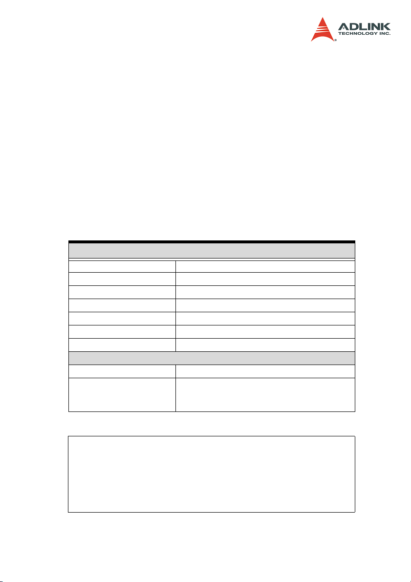
PCI-7841 Layout:
Terminator Configuration
A 120 Ohm terminal resistor is installed for each port, while JP1
enables the terminal resistor for port0 and JP2 enables the terminal resistor for port 1
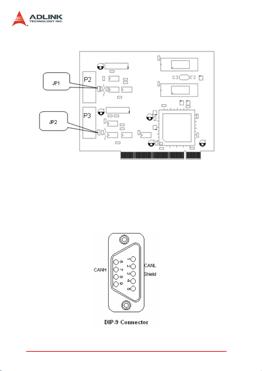
Connector Pin Definition
P3 and P4 are CAN connectors; pin definition is as follows:
8Installation
Page 17

2.3 Installing cPCI-7841
What you have
In addition to this User's Manual, the package includes the following items:
X cPCI-7841 Dual Port Compact-PCI Isolated CAN Interface
Card
X ADLINK CD-ROM
If any of these items is missing or damaged, contact the dealer
from whom you purchased the product. Save the shipping materials and carton in case you want to ship or store the product in the
future.
cPCI-7841 Layout
Terminator Configuration
A 120 Ohm terminal resistor is installed for each port, while JP1
enables the terminal resistor for port0 and JP2 enables the terminal resistor for port 1
Installation 9
Page 18
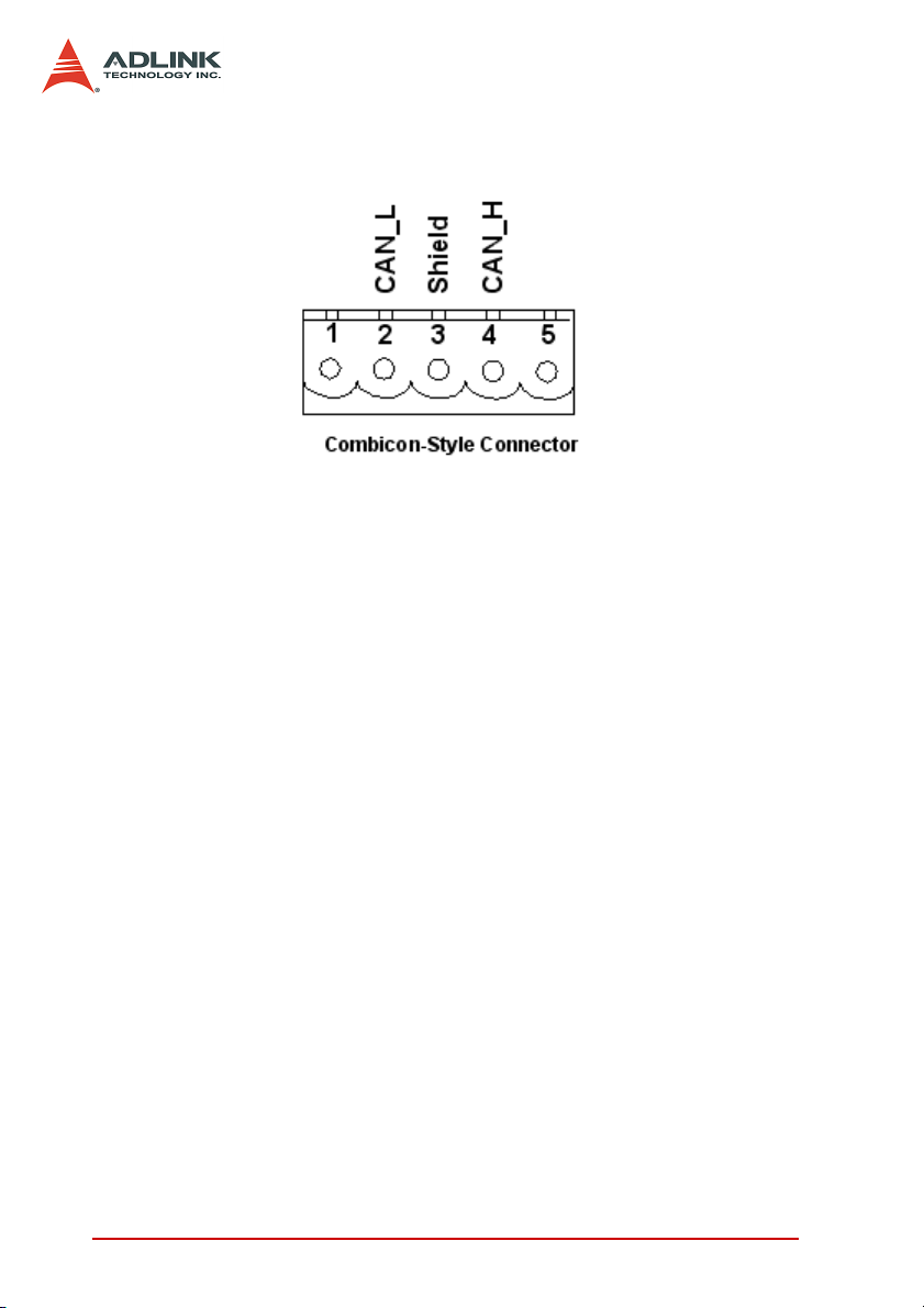
Connector Pin Definition
J1 and J2 are CAN connectors; pin definition is as follows:
2.4 Installing PM-7841
What you have
In addition to this User's Manual, the package includes the following items:
X PM-7841 Dual Port PC-104 Isolated CAN Interface Card
X ADLINK CD-ROM
If any of these items is missing or damaged, contact the dealer
from whom you purchased the product. Save the shipping materials and carton in case you want to ship or store the product in the
future.
10 Installation
Page 19
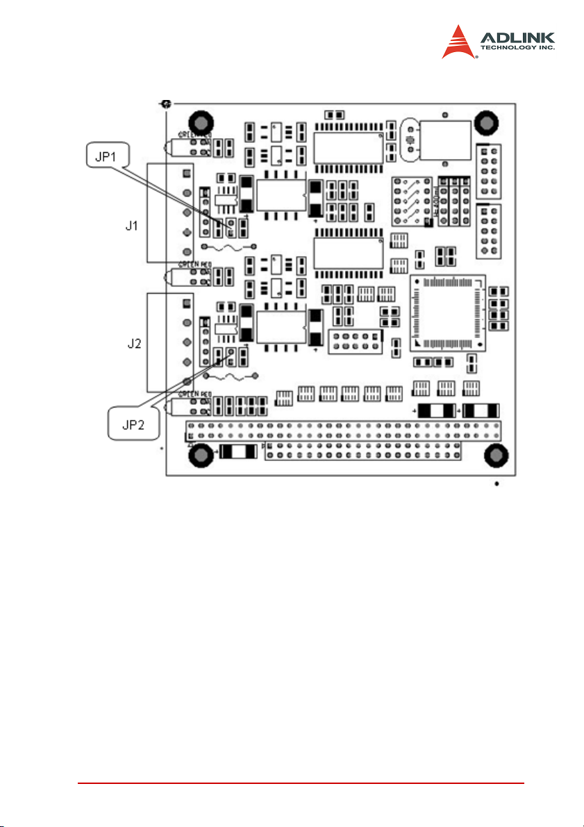
PM-7841 Layout
Terminator Configuration
A 120 Ohm terminal resistor is installed for each port, while JP1
enables the.
terminal resistor for port0 and JP2 enables the terminal resistor for
port 1.
Installation 11
Page 20

Connector Pin Define
J1 and J2 are CAN connectors; pin definition is as follows:
2.5 Jumper and DIP Switch Description
You can configure the output of each channel and base address
by setting jumpers and DIP switches on the PM-7841. The card's
jumpers and switches are preset at the factory. Under normal circumstances, you should not need to change the jumper settings.
A jumper switch is closed (sometimes referred to as "shorted")
with the plastic cap inserted over two pins of the jumper. A jumper
is open with the plastic cap inserted over one or no pin(s) of the
jumper.
2.6 Base Address Setting
The PM-7841 requires 16 consecutive address locations in I/O
address space. The base address of the PM-7841 is restricted by
the following conditions.
1. The base address must be within the range 200hex to
3F0hex.
2. The base address should not conflict with any PC
reserved I/O address.
The PM-7841's I/O port base address is selectable by an 5 position DIP switch SW1 ( refer to Table 2.1). The address settings for
I/O port from Hex 200 to Hex 3F0 is described in Table 2.2 below.
The default base address of your PM-7841 is set to hex 200 in the
factory( see Figure below).
12 Installation
Page 21

SW1 : Base Address = 0x200
ON
12345
A ( 8 7 6 5 4 )
Figure 2-1: Default Base Address Configuration
(*): default setting ON : 0
X: don't care OFF : 1
Note: A4,…, A9 correspond to PC-104(ISA) bus address lines.
Installation 13
Page 22

2.7 IRQ Level Setting
A hardware interrupt can be triggered by the external Interrupt signal which is from JP3 ad JP4.
The jumper setting is specified as below:
Note: Be aware that there is no other add-on cards sharing the
same interrupt level in the system.
Interrupt Default Setting = IRQ15
(IRQ)
X 15 12 11 10
Figure 2-2: IRQ Settings
9 7 6 5 3
14 Installation
Page 23

3 Function Reference
The cPCI/PCI-7841 functions are organize into the following sections:
X CAN layer functions
X Card Initialization and configuration functions
X CAN layer I/O functions
X CAN layer status functions
X CAN layer Error and Event Handling functions
X DeviceNet layer functions
X Send and Receive packet functions
X Connection establish and release functions
X DeviceNet object class functions
The particular functions associated with each function are presented in next page.
3.1 Functions Table
CAN layer functions
Function Type Function Name
PM-7841 Initial PM7841_Install()
GetDriverVersion()
CanOpenDriver()
CanCloseDriver()
CanConfigPort()
CanDetectBaudrate()
_7841_Read()
_7841_Write()
CanEnableReceive()
CanDisableReceive()
CanSendMsg()
CanRcvMsg()
CanGetRcvCnt()
Function Reference 15
Page 24

CanClearOverrun()
CanClearRxBuffer()
CanClearTxBuffer()
CanGetErrorCode()
CanGetErrorWarningLimit()
CanSetErrorWarningLimit()
CanGetRxErrorCount()
CanGetTxErrorCount()
CanSetTxErrorCount()
CanGetPortStatus()
CanGetLedStatus()1
CanSetLedStatus()1
Error and Event handling functions
Operation System Function Name
DOS
Windows 95/98/NT CanInstallEvent()
CanInstallCallBack()
CanRemoveCallBack()
Note: only for compact PCI and PC-104 version.
PORT_STRUCT structure define
The PORT_STRUCT structure defines the mode of id-mode,
acceptance code, acceptance mask and baud rate of a physical
CAN port. It is used by the CanPortConfig(), and CanGetPortStatus() functions.
typedef struct _tagPORT_STRUCT
{
int mode; // 0 for 11-bit; 1 for 29-
bit
DWORD accCode, accMask;
int baudrate;
BYTE brp, tseg1, tseg2;// Reserved
BYTE sjw, sam; // Reserved
}PORT_STRUCT;
16 Function Reference
Page 25

Members
mode: 0 means using 11-bit in CAN-ID field
1 means using 29-bit in CAN-ID field.
accCode:Acceptance Code for CAN controller.
accMask:Acceptance Mask for CAN controller.
baudrate:Baud rate setting for the CAN controller.
Value Baudrate
0 125 Kbps
1 250 Kbps
2 500 Kbps
31M bps
CanPortConfig(), CanGetPortStatus(), and PORT_STATUS structure
PORT_STATUS structure define
The PORT_STATUS structure defines the status register and
PORT_STRUCT of CAN port. It is used by the CanGetPortStatus()
functions.
typedef struct _tagPORT_STATUS
{
PORT_STRUCT port;
PORT_REG status;
}PORT_STATUS;
Members
port: PORT_STRUCT data
status: status is the status register
mapping of CAN controller.
typedef union _tagPORT_REG
{
struct PORTREG_BIT bit;
unsigned short reg;
}PORT_REG;
struct PORTREG_BIT
{
unsigned short RxBuffer: 1;
unsigned short DataOverrun: 1;
unsigned short TxBuffer: 1;
Function Reference 17
Page 26

unsigned short TxEnd: 1;
unsigned short RxStatus: 1;
unsigned short TxStatus: 1;
unsigned short ErrorStatus: 1;
unsigned short BusStatus: 1;
unsigned short reserved: 8;
};
See Also
CanGetPortStatus(), and PORT_STATUS structure
CAN_PACKET structure define
The CAN_PACKET structure defines the packet format of CAN
packet. It is used by the CanSendMsg(), and CanRcvMsg() functions.
typedef struct _tagCAN_PACKET
{
DWORD CAN_ID;
BYTE rtr;
BYTE len;
BYTE data[8]
DWORD time;
BYTE reserved
}CAN_PACKET;
Members
CAN_ID: CAN ID field (32-bit unsigned integer)
rtr: CAN RTR bit.
len: Length of data field.
data: Data (8 bytes maximum)
time: Reserved for future use
reserved: Reserved byte
See Also
CanSendMsg(), and CanRcvMsg()
18 Function Reference
Page 27

DEVICENET_PACKET structure define
The DEVICENET_PACKET structure defines the packet format of
DeviceNet packet. It is widely used by the DeviceNet layer functions.
typedef struct _tagDEVICENET_PACKET
{
BYTE Group;
BYTE MAC_ID;
BYTE HostMAC_ID;
BYTE MESSAGE_ID;
BYTE len;
BYTE data[8];
DWORD time;
BYTE reserved;
}DEVICENET_PACKET;
Members
Group: Group of DeviceNet packet.
MAC_ID: Address of destination.
HostMAC_ID:Address of source.
MESSAGE_ID:Message ID of DeviceNet packet.
len: Length of data field.
data: Data (8 bytes maximum).
See Also
SendDeviceNetPacket(), and RcvDeviceNetPacket()
Function Reference 19
Page 28

3.2 CAN LAYER Functions
CAN-layer Card Initialization Functions
PM7841_Install(base, irq_chn, 0xd000)
Purpose Get the version of driver
Prototype C/C++
int PM7841_Install(int baseAddr, int irq_chn, int memorySpace)
Parameters baseAddr:Base Address of PM-7841(DIP
Switch)
Irq_chn: IRQ channel (Jumpper)
MemorySpace: Memory Mapping Range
Return Value A signed integer
0 : Successful
-1: Failed
Remarks PM7841 is PC104(ISA) CAN interface card.
It will need 32-bytes I/O space and 1K
memory space.
See Also none
Usage C/C++
#include “pm7841.h”
int ret;
ret = PM7841_Install(
baseAddr,
irq_ch,
memorySpace);
GetDriverVersion()
Purpose Get the version of driver
Prototype C/C++
WORD GetDriverVersion(void)
Parameters none
Return Value A 16-bit unsigned integer
High byte is the major version
Low byte is the major version
20 Function Reference
Page 29

Remarks Call this function to retrieve the version of
current using driver. This function is for your
program to get the version of library and
dynamic-linked library.
See Also none
Usage C/C++
#include “pci7841.h”
WORD version = GetDriverVersion();
majorVersion = version >> 8;
minorVersion = version & 0x00FF;
CanOpenDriver()
Purpose Open a specific port, and initialize driver.
Prototype C/C++
int CanOpenDriver(int card, int port))
Parameters card: index of card
port: index of port
Return Value Return a handle for open port
-1 if error occurs
Remarks Call this function to open a port
Under DOS operation system, you will
receive –1 if there is not enough memory. If
writing program for the Windows system. It
will return -1, if you want to open a port had
been opened. And you must use Can-
CloseDriver() to close the port after using.
See Also CanCloseDriver()
Usage C/C++
#include “pci7841.h”
int handle = CanOpenDriver();
CanSendMsg(handle, &msg);
CanCloseDriver(handle);
CanCloseDriver()
Purpose Close an opened port, and release driver.
Prototype C/C++
int CanCloseDriver(int handle)
Function Reference 21
Page 30

Parameters handle : handle retrieve from CanOpen-
Driver()
Port : index of port
Return Value Return 0 if successful
-1 if error occurs
Remarks Call this function to close a port.
See Also CanOpenDriver()
Usage See usage of CanOpenDriver().
CanConfigPort()
Purpose Configure properties of a port
Prototype C/C++
int CanConfigPort(int handle,
PORT_STRUCT *ptrStruct)
Parameters handle : handle retrieve from CanOpen-
Driver()
PtrStruct : a pointer of PORT_STRUCT
type
Return Value Return 0 is successful
-1 if error occurs
Remarks Configure a port that had been opened.
The properties of a CAN port such as baud
rate, acceptance code, acceptance mask,
operate mode. After configuration is over,
the port is ready to send and receive data.
See Also PORT_STRUCT structure define
Usage C/C++
#include “pci7841.h
PORT_STRUCT port_struct;
int handle = CanOpenDriver(0, 0);//Open port 0 of
card 0
port_struct.mode = 0;//CAN2.0A (11-bit CAN id)
port_struct.accCode = 0;//This setting of
acceptance code and
port_struct.accMask = 0x7FF; //mask enable all
MAC_IDs input
port_struct.baudrate = 0;//125K bps
CanConfigPort(handle, &port_struct);
22 Function Reference
Page 31

CanCloseDriver(handle);
CanDetectBaudrate()
Purpose Perform auto-detect baud rate algorithm.
Prototype C/C++
int CanDetectBaudrate(int handle, int
miliSecs)
Parameters handle: handle retrieve from CanOpen-
Driver()
MiliSecs: timeout time(ms)
Return Value Return –1 if error occurs
Others is the baudrate
Value Baudrate
0 125 Kbps
1 250 Kbps
2 500 Kbps
31 Mbps
Remarks Call this function to detect the baud rate of
a port.
The function performs an algorithm to
detect your baud rate. It needs that there
are activities on the network. And it will
return a –1 when detecting no activity on
the network or time was exceeded.
See Also none
Usage C/C++
#include “pci7841.h
PORT_STRUCT port_struct;”
int handle = CanOpenDriver();
port_struct.mode = 0;//CAN2.0A (11-bit CAN id)
port_struct.accCode = 0;//This setting of
acceptance code and
port_struct.accMask = 0x7FF;//mask enable all
MAC_IDs input
port_struct.baudrate = CanDetectBaudrate(handle,
1000):
Function Reference 23
Page 32

CanConfigPort(handle, &port_struct);
CanCloseDriver(handle);
Visual Basic(Windows 95/98/NT)
CanRead()
Purpose Direct read the register of PCI-7841.
Prototype C/C++
BYTE CanRead(int handle, int offset)
Parameters handle : handle retrieve from CanOpen-
Driver()
offset : offset of register
Return Value Return data read from port.
Remarks Direct read the register of PCI-7841.
See Also CanWrite()
Usage none
CanWrite()
Purpose Direct write the register of PCI-7841.
Prototype C/C++
void CanWrite(int handle, int offset, BYTE
data)
Parameters handle : handle retrieve from CanOpen-
Driver()
Offset : offset of register
data : data write to the port
Return Value none
Remarks Call this function to directly write a register
of PCI-7841
See Also CanRead()
Usage none
CAN-layer I/O Functions
CanEnableReceive()
Purpose Enable receive of a CAN port.
Prototype C/C++
24 Function Reference
Page 33

void CanEnableReceive(int handle);
Parameters handle : handle retrieve from CanOpen-
Driver()
Return Value none
Remarks Call this function to enable receive.
Any packet on the network that can induce
a interrupt on your computer. If that packet
can pass your acceptance code and accep-
tance mask setting. So if your program
doesn’t want to be disturbed. You can call
CanDisableReceive() to disable receive
and CanEnableReceive() to enable
receives.
See Also CanDisableReceive()
Usage none
CanDisableReceive()
Purpose Disable receive of a CAN port.
Prototype C/C++
void CanEnableReceive(int handle);
Parameters handle : handle retrieve from CanOpen-
Driver()
Return Value none
Remarks Please refer the CanEnableReceive()
See Also CanEnableReceive()
Usage none
CanSendMsg()
Purpose Send can packet to a port
Prototype C/C++
int CanSendMsg(int handle, CAN_PACKET
*packet);
Parameters handle : handle retrieve from CanOpen-
Driver()
Packet : CAN_PACKET data
Return Value Return 0 is successful
Function Reference 25
Page 34

-1 if error occurs
Remarks Send a message to an opened CAN port.
Actually, this function copies the data to the
sending queue. Error occurs when the port
has not been opened yet or the packet is a
NULL pointer. You can use the Error and
Event handling functions to handle the
exceptions.
See Also CanRcvMsg()
Usage C/C++
#include “pci7841.h
PORT_STRUCT port_struct;
CAN_PACKET sndPacket, rcvPacket;
int handle = CanOpenDriver(0, 0);//open the port
0 of card 0
CanConfigPort(handle, &port_struct);
CanSendMsg(handle, &sndPacket);
if(CanRcvMsg(handle, &rcvPacket) == 0)
{
}
CanCloseDriver(handle);
CanRcvMsg()
Purpose Receive a can packet from a port
Prototype C/C++
int CanSendMsg(int handle, CAN_PACKET
*packet);
Parameters handle : handle retrieve from CanOpen-
Driver()
Packet : CAN_PACKET data
Return Value Return 0 is successful
-1 if error occurs
Remarks Receive a message from an opened CAN
port.
There are only 64-bytes FIFO under hard-
ware. It can store from 3 to 21 packets. So
there are memory buffer under driver. When
data comes, the driver would move it from
26 Function Reference
Page 35

card to memory. It starts after your port configuration is done. This function copies the
buffer to your application. So if your program has the critical section to process the
data on the network. We suggest that you
can call the CanClearBuffer() to clear the
buffer first. Error would be happened most
under the following conditions:
1. You want to access a port that has not be
opened.
2. Your packet is a NULL pointer.
3. The receive buffer is empty.
You can use the Status handling functions
to handle the exceptions.
See Also CanSendMsg()
Usage See the CanSendMsg()
CAN-layer Status Functions
CanClearOverrun()
Purpose Clear data overrun status
Prototype C/C++
void CanClearOverrun(int handle)
Parameters handle : handle retrieve from CanOpen-
Driver()
Return Value none
Remarks Clear the data overrun status
Sometimes if your system has heavy load,
and the bus is busy. The data overrun
would be signalled. A Data Overrun signals,
that data are lost, possibly causing incon-
sistencies in the system.
See Also CanRcvMsg()
Usage C/C++
#include “pci7841.h
int handle = CanOpenDriver(0, 0);//open the port
0 of card 0
Function Reference 27
Page 36

….
CanClearOverrun(handle);
CanCloseDriver(handle);
CanClearRxBuffer()
Purpose Clear data in the receive buffer
Prototype C/C++
void CanClearRxBuffer(int handle)
Parameters handle : handle retrieve from CanOpen-
Driver()
Return Value none
Remarks Clear the data in the receive buffer
There are 2-type of buffer defined in the
driver. First one is the FIFO in the card, the
second one is the memory space inside the
driver. Both of them would be cleared after
using this function.
See Also CanRcvMsg()
Usage C/C++
#include “pci7841.h
int handle = CanOpenDriver(0, 0);//open the port
0 of card 0
….
CanClearRxBuffer(handle);
CanCloseDriver(handle);
CanClearTxBuffer()
Purpose Clear Transmit Buffer
Prototype C/C++
void CanClearTxBuffer(int handle)
Parameters handle : handle retrieve from CanOpen-
Driver()
Return Value none
Remarks Clear the data in the transmit buffer.
Under a busy DeviceNet Network, your
transmit request may not be done due to
the busy in the network. The hardware will
send it automatically when bus is free. The
28 Function Reference
Page 37

un-send message would be stored in the
memory of the driver. The sequence of outgoing message is the FIRST-IN-FIRSTOUT. According this algorithm, if your program need to send an emergency data, you
can clear the transmit buffer and send it
again.
See Also CanRcvMsg()
Usage C/C++
#include “pci7841.h
int handle = CanOpenDriver(0, 0);//open the port
0 of card 0
….
CanClearTxBuffer(handle);
CanCloseDriver(handle);
CanGetErrorCode()
Purpose Get the Error Code
Prototype C/C++
BYTE CanGetErrorCode(int handle)
Parameters handle : handle retrieve from CanOpen-
Driver()
Return Value error code
Return error code is an 8-bit data
Bit Symbol Name Value Function
7 ERRC1 Error Code 1
6 ERRC0 Error Code 0
5 DIR Direction
4 SEG4 Segment 4
3 SEG3 Segment 3
2 SEG2 Segment 2
1 SEG1 Segment 1
0 SEG0 Segment 0
Function Reference 29
1 Rx error occurred during reception
0 Tx error occurred during ransmission
Page 38

Bit interpretation of ERRC1 and ERRC2
Bit ERRC1 Bit ERRC2 Function
0 0 bit error
0 1 form error
1 0 stuff error
1 1 other type of error
Bit interpretation of SEG4 to SEG 0
SEG4 SEG3 SEG2 SEG1 SEG0 Function
00011 start of frame
00010 ID.28 to ID.21
00110 ID.20 to ID.18
00100 bit SRTR
00101 bit IDE
00111 ID.17 to ID.13
01111 ID.12 to ID.5
01110 ID.4 to ID.0
01100 RTR bit
01101 reserved bit 1
01001 reserved bit 0
01011Data length code
01010 Data field
01000 CRC sequence
11000 CRC delimiter
11001acknowledge slot
11010 end of frame
10010 intermission
10001 active error flag
10110passive error flag
10011tolerate dominant bits
10111 error delimiter
11100 overload flag
30 Function Reference
Page 39

Remarks Get the information about the type and
location of errors on the bus.
When a bus error occurs, if your program
installed the call-back function or error-handling event. The error-bit position would be
captured into the card. The value would be
fixed in the card until your program read it
back.
See Also CanGetErrorWarningLimit(),
CanSetErrorWarningLimit()
Usage C/C++
#include “pci7841.h
int handle = CanOpenDriver(0, 0);//open the port
0 of card 0
….
BYTE data = CanGetErrorCode();
CanCloseDriver(handle);
CanSetErrorWarningLimit()
Purpose Set the Error Warning Limit
Prototype C/C++
void CanSetErrorWarningLimit(int handle,
BYTE value)
Parameters handle : handle retrieve from CanOpen-
Driver()
Value : Error Warning Limit
Return Value none
Remarks Set the error warning limit. If your program
has installed the error warning event or call-
back function. The error warning will be sig-
naled after the value of error counter pass-
ing the limit you set.
See Also CanGetErrorWarningLimit()
Usage C/C++
#include “pci7841.h
int handle = CanOpenDriver(0, 0);//open the port
0 of card 0
….
Function Reference 31
Page 40

CanSetErrorWarning(handle, 96);
CanCloseDriver(handle);
CanGetErrorWarningLimit()
Purpose Get the Error Warning Limit
Prototype C/C++
BYTE CanGetErrorWarningLimit(int handle)
Visual Basic(Windows 95/98/NT)
Parameters handle : handle retrieve from CanOpen-
Driver()
Return Value 0-255 (Error warning limit value)
Remarks Get the error warning limit
See Also CanSetErrorWarningLimit()
Usage C/C++
#include “pci7841.h
int handle = CanOpenDriver(0, 0);//open the port
0 of card 0
….
BYTE limit = CanClearOverrun(handle);
CanCloseDriver(handle);
CanGetRxErrorCount()
Purpose Get the current value of the receive error
counter
Prototype C/C++
BYTE CanGetRxErrorCount(int handle)
Parameters handle : handle retrieve from CanOpen-
Driver()
Return Value value
Remarks This function reflects the current of the
receive error counter. After hardware reset
happened, the value returned would be ini-
tialized to 0. If a bus-off event occurs, the
returned value would be 0.
See Also CanRcvMsg()
Usage C/C++
32 Function Reference
Page 41

#include “pci7841.h
int handle = CanOpenDriver(0, 0);//open the port
0 of card 0
….
BYTE error_count = CanGetRxErrorCount();
CanCloseDriver(handle);
CanGetTxErrorCount()
Purpose Get the current value of the transmit error
counter
Prototype C/C++
BYTE CanGetTxErrorCount(int handle)
Parameters handle : handle retrieve from CanOpen-
Driver()
Return Value value
Remarks This function reflects the current of the
transmit error counter. After hardware reset
happened, the value would set to 127. A
bus-off event occurs when the value
reaches 255. You can call the CanSetTxEr-
rorCount() to set the value from 0 to 254 to
clear the bus-off event.
See Also CanRcvMsg()
Usage C/C++
#include “pci7841.h
int handle = CanOpenDriver(0, 0);//open the port
0 of card 0
….
BYTE error_count = CanGetTxErrorCount(handle);
CanCloseDriver(handle);
CanSetTxErrorCount()
Purpose Set the current value of the transmit error
counter
Prototype C/C++
void CanSetTxErrorCount(int handle, BYTE
value)
Function Reference 33
Page 42

Parameters handle : handle retrieve from CanOpen-
Driver()
value : a byte value
Return Value None
Remarks This function set the current of the transmit
error counter.
Please see the remark of CanGetTxError-
Count().
See Also CanRcvMsg()
Usage C/C++
#include “pci7841.h
int handle = CanOpenDriver(0, 0);//open the port
0 of card 0
….
CanSetTxErrorCount(handle, 0);
CanCloseDriver(handle);
CanGetPortStatus()
Purpose Get Port Status
Prototype C/C++
int CanGetPortStatus(int handle,
PORT_STATUS *PortStatus)
Parameters handle : handle retrieve from CanOpen-
Driver()
PortStatus : Pointer of PORT_STATUS
structure
Return Value No Error: 0
Error: -1
Remarks Get Port Status(See the structure define for
detailed description)
See Also
Usage C/C++
#include “pci7841.h
PORT_STATUS port_status;
int handle = CanOpenDriver(0, 0);// open the port
0 of card 0
CanGetPortStatus(&port_status);
CanClearOverrun();
34 Function Reference
Page 43

CanCloseDriver(handle);
CanGetLedStatus()
Purpose Get the LED status of cPCI-7841 and PM-
7841
Prototype C/C++
BYTE CanGetLedStatus (int card, int
index);
Parameters card : card number
Index : index of LED
Return Value status of Led
Value Function
0 Led Off
1Led On
Remarks Get the status of Led
This function supports the cPCI-7841 and
PM-7841.
See Also CanSetLEDStatus()
Usage C/C++
#include “pci7841.h
int handle = CanOpenDriver(0, 0);//open the port
0 of card 0
….
BYTE flag = CanGetLedStatus(0, 0);;
CanCloseDriver(handle);
CanSetLedStatus()
Purpose Set the Led Status of cPCI-7841
Prototype C/C++
void CanSetLedStatus(int card, int index,
int flashMode);
Parameters card : card number
Index : index of Led
flashMode :
Value Function
Function Reference 35
Page 44

0Led Off
1 Led On
Return Value none
Remarks Set Led status of cPCI-7841 and PM-7841
This function supports the cPCI-7841 and
PM-7841
See Also CanRcvMsg()
Usage C/C++
#include “pci7841.h
int handle = CanOpenDriver(0, 0);//open the port
0 of card 0
….
CanSetLedStatus(0, 0, 2);//Set Led to flash
CanCloseDriver(handle);
CanGetRcvCnt()
Purpose Get the how many message in the FIFO
Prototype C/C++
int _stdcall CanGetRcvCnt(int handle)
Parameters handle : handle retrieve from CanOpen-
Driver()
Return Value value indicates the left unread messages in
the FIFO.
Remarks Get the unread message count in the FIFO.
Because the interrupt would be very busy
while CAN bus is busy. There is possibility
to lost the event in Windows system. A way
to solve to this problem is to call this function at free time while program running. You
also can call this function to make sure that
receiving FIFO is empty.
See Also CanGetReceiveEvent()
Usage C/C++
#include “pci7841.h
int handle = CanOpenDriver(0, 0);//open the port
0 of card 0
…..
int count = CanGetRcvCnt(handle);.
36 Function Reference
Page 45

Error and Event Handling Functions
When the exception occurs, your program may need to take some
algorithm to recover the problem. The following functions are operation-system depended functions. You should care about the
restriction in the operation-system.
DOS Environment
CanInstallCallBack()
Purpose Install callback function of event under DOS
environment
Prototype C/C++ (DOS)
void far*CanInstallCallBack(int handle, int
index, void (far* proc)() );
Parameters handle : handle retrieve from CanOpen-
Driver()
Index : event type
Index Type
2 Error Warning
3 Data Overrun
4Wake Up
5 Error Passive
6 Arbitration Lost
7 Bus Error
void (far *proc)() : Call-back function
The suggested prototype of the call-back
function is like void (far ErrorWarning)();
Return Value Previous call back function (NULL when
there is no Call back installed)
Remarks Install the call-back function for event han-
dling
In normal state, all hardware interrupt of
cPCI/PCI-7841 wouldn’t be set except
receive and transmit interrupt. After calling
the CanInstallCallBack(), the corresponding
interrupt would be activated. The interrupt
Function Reference 37
Page 46

occurs when the event happened. It will not
be disabled until using CanRemoveCallBack() or a hardware reset.
Actually, the call-back function is a part of
ISR. You need to care about the DOS reentrance problem, and returns as soon as
possible to preventing the lost of data.
See Also CanRemoveCallBack()
Usage C/C++(DOS)
#include “pci7841.h
void (far ErrorWarning)();
int handle = CanOpenDriver(0, 0);
// open the port 0 of card 0
…
// Installs the ErrorWarning handling event and
stores the previous one.
void (far *backup) = CanInstallCallBack(0, 2,
ErrorWarning);
CanRemoveCallBack(0, 2, NULL);//Remove the call-
back function
CanCloseDriver(handle);
CanRemoveCallBack()
Purpose Remove the callback function of event
under DOS environment
Prototype C/C++(DOS)
int CanRemoveCallBack(int handle, int
index, void (far* proc)() );
Parameters handle : handle retrieve from CanOpen-
Driver()
Index : event type
Index Type
2 Error Warning
3 Data Overrun
4 Wake Up
5 Error Passive
6 Arbitration Lost
38 Function Reference
Page 47

7 Bus Error
void (far *proc)() : Previous call-back function
Return Value Return 0 is successful
-1 if error occurs
Remarks Install the call-back function for event han-
dling
In normal state, all hardware interrupt of
cPCI/PCI-7841 wouldn’t be set except
receive and transmit interrupt. After calling
the CanInstallCallBack(), the corresponding
interrupt would be activated. The interrupt
occurs when the event happened. It will not
be disabled until using CanRemoveCallBack() or a hardware reset.
Actually, the call-back function is a part of
ISR. You need to care about the DOS reentrance problem, and returns as soon as
possible to preventing the lost of data.
See Also CanRemoveCallBack()
Usage C/C++ (DOS)
#include “pci7841.h
void (far ErrorWarning)();
int handle = CanOpenDriver(0, 0);//open the port
0 of card 0
…
// Installs the ErrorWarning handling event and
stores the previous one.
void (far *backup) = CanInstallCallBack(0, 2,
ErrorWarning);
CanRemoveCallBack(0, 2, NULL);//Remove the call-
back function
Function Reference 39
Page 48

CanCloseDriver(handle);
Windows 95/98 Environment
CanGetReceiveEvent()
Purpose Install the event under Windows 95/98/NT
system
Prototype C/C++ (Windows 95/98/NT)
void CanGetReceiveEvent(int handle,
HANDLE *hevent);
Parameters handle : handle retrieve from CanOpen-
Driver()
Heven : HANDLE point for receive event
Return Value none
Remarks Retrieve receive notify event
Under Windows 95/98/NT environment,
your program can wait the input message
by waiting an event. You can refer to follow-
ing program to use this function. But the
CAN system is a heavy-load system. Under
the full speed(of course, it depends on your
system), the hardware receives the mes-
sage faster than the event occurs. Under
this condition, the event could be combined
by OS. So the total count of event may be
less than actually receive. You can call the
CanGetRcvCnt() to retrieve the unread
message in the driver’s FIFO.
See Also CanGetRcvCnt()
Usage C/C++ (Windows 95/98/NT)
#include “pci7841.h
HANDLE recvEvent0;
int handle = CanOpenDriver(0, 0);
// open the port 0 of card 0
int count1;
CanGetReceiveEvent(handle, rcvEvent0);
if(WaitForSingleObject(rcvEvent0, INFINITE)
== WAIT_OBJECT_0)
{
40 Function Reference
Page 49

// You need not to call ResetEvent()…..
err=CanRcvMsg(handle,&rcvMsg[0]
[rcvPatterns[0]]);
rcvPatterns[0]++;
}
cout1 = CanGetRcvCnt(handle[0]);
// To retrieve number of unread
// in the FIFO
CanInstallEvent()
Purpose Install the event under Windows 95/98/NT
system
Prototype C/C++ (Windows 95/98/NT)
int CanInstallEvent(int handle, int index,
HANDLE hEvent);
Parameters handle : handle retrieve from CanOpen-
Driver()
Index : event type
Index Type
2 Error Warning
3 Data Overrun
4Wake Up
5 Error Passive
6 Arbitration Lost
7 Bus Error
HEvent : HANDLE created from CreateEvent()(Win32 SDK)
Return Value Return 0 is successful
-1 if error occurs
Remarks Install the notify event
Unlike the Dos environment, there is only
one error handling function under Windows
95/98/NT environment. First you need to
create an event object, and send it to the
DLL. The DLL would make a registry in the
kernel and pass it to the VxD(SYS in NT
Function Reference 41
Page 50

system). You can’t release the event object
you created, because it was attached to the
VxD. The VxD would release the event
object when you installed another event.
One way to disable the event handling is
that you install another event which handle
is NULL (ex: CanInstallEvent(handle, index,
NULL)). And you can create a thread to
handle the error event.
See Also CanRemoveCallBack(),CanInstallCall-
Back()
Usage C/C++ (Windows 95/98/NT)
#include “pci7841.h
int handle = CanOpenDriver(0, 0);
// open the port 0 of card 0
…
// Installs the ErrorWarning handling event and
stores the previous one.
HANDLE hEvent = CreateEvent(NULL, FALSE, TRUE,
“ErrorWarning”);
CanInstallEvent(0, 2, hEvent);
//..create a thread ….
Thread function
WaitForSingleObject(hEvent, INFINITE);
ResetEvent(hEvent);
// Event handling
42 Function Reference
Page 51

Warranty Policy
Thank you for choosing ADLINK. To understand your rights and
enjoy all the after-sales services we offer, please read the following carefully.
1. Before using ADLINK’s products please read the user man-
ual and follow the instructions exactly. When sending in
damaged products for repair, please attach an RMA application form which can be downloaded from: http://
rma.adlinktech.com/policy/.
2. All ADLINK products come with a limited two-year war-
ranty, one year for products bought in China:
X The warranty period starts on the day the product is
shipped from ADLINK’s factory.
X Peripherals and third-party products not manufactured
by ADLINK will be covered by the original manufactur-
ers' warranty.
X For products containing storage devices (hard drives,
flash cards, etc.), please back up your data before send-
ing them for repair. ADLINK is not responsible for any
loss of data.
X Please ensure the use of properly licensed software with
our systems. ADLINK does not condone the use of
pirated software and will not service systems using such
software. ADLINK will not be held legally responsible for
products shipped with unlicensed software installed by
the user.
X For general repairs, please do not include peripheral
accessories. If peripherals need to be included, be cer-
tain to specify which items you sent on the RMA Request
& Confirmation Form. ADLINK is not responsible for
items not listed on the RMA Request & Confirmation
Form.
Warranty Policy 43
Page 52

3. Our repair service is not covered by ADLINK's guarantee
in the following situations:
X Damage caused by not following instructions in the
User's Manual.
X Damage caused by carelessness on the user's part dur-
ing product transportation.
X Damage caused by fire, earthquakes, floods, lightening,
pollution, other acts of God, and/or incorrect usage of
voltage transformers.
X Damage caused by unsuitable storage environments
(i.e. high temperatures, high humidity, or volatile chemicals).
X Damage caused by leakage of battery fluid during or
after change of batteries by customer/user.
X Damage from improper repair by unauthorized ADLINK
technicians.
X Products with altered and/or damaged serial numbers
are not entitled to our service.
X This warranty is not transferable or extendible.
X Other categories not protected under our warranty.
4. Customers are responsible for shipping costs to transport
damaged products to our company or sales office.
5. To ensure the speed and quality of product repair, please
download an RMA application form from our company website: http://rma.adlinktech.com/policy. Damaged products
with attached RMA forms receive priority.
If you have any further questions, please email our FAE staff:
service@adlinktech.com.
44 Warranty Policy
 Loading...