

Page 1

PCI-7260
8-CH High-Power Relay Outputs &
8-CH Isolated Digital Inputs Card
User’s Manual
Manual Rev. 2.01
Revision Date: December 21, 2006
Part No: 50-12019-100
Advance Technologies; Automate the World.
Page 2

Copyright 2005 ADLINK TECHNOLOGY INC.
All Rights Reserved.
The information in this document is subject to change without prior
notice in order to improve reliability, design, and function and does
not represent a commitment on the part of the manufacturer.
In no event will the manufacturer be liable for direct, indirect, special, incidental, or consequential damages arising out of the use or
inability to use the product or documentation, even if advised of
the possibility of such damages.
This document contains proprietary information protected by copyright. All rights are reserved. No part of this manual may be reproduced by any mechanical, electronic, or other means in any form
without prior written permission of the manufacturer.
Trademarks
Product names mentioned herein are used for identification purposes only and may be trademarks and/or registered trademarks
of their respective companies.
Page 3
Getting Service from ADLINK
Customer Satisfaction is top priority for ADLINK Technology Inc.
Please contact us should you require any service or assistance.
ADLINK TECHNOLOGY INC.
Web Site: http://www.adlinktech.com
Sales & Service: Service@adlinktech.com
TEL: +886-2-82265877
FAX: +886-2-82265717
Address: 9F, No. 166, Jian Yi Road, Chungho City,
Taipei, 235 Taiwan
Please email or FAX this completed service form for prompt and
satisfactory service.
Company Information
Company/Organization
Contact Person
E-mail Address
Address
Country
TEL FAX:
Web Site
Product Information
Product Model
OS:
Environment
M/B: CPU:
Chipset: Bios:
Please give a detailed description of the problem(s):
Page 4

Page 5

Table of Contents
1 Introduction ........................................................................ 1
1.1 Features............................................................................... 2
1.2 Applications ......................................................................... 3
1.3 Specifications....................................................................... 4
1.4 Software Support ................................................................. 6
Programming Library ...................................................... 6
DAQ-LVIEW PnP ............................................................ 6
2 Installation .......................................................................... 7
2.1 What you have..................................................................... 7
2.2 Unpacking............................................................................ 7
2.3 PCB Layout.......................................................................... 8
2.4 AC/non-AC filter setting (JP1).............................................. 9
2.5 Isolated digital input connector (JP2)................................. 10
2.6 Relay status output connector (JP3).................................. 11
2.7 Board ID (S1)..................................................................... 12
2.8 Initial state DIP switch (S2) ................................................ 13
2.9 Emergency shutdown state DIP switch (S3)...................... 13
2.10 Connector Pin Assignments (CN1).................................... 14
3 Register Format................................................................ 15
3.1 I/O Address Map................................................................ 16
3.2 Relay Output Control Register........................................... 17
3.3 WDTimer Load Config Register......................................... 18
3.4 Relay Output Read Back Register ..................................... 19
3.5 Emergency Shutdown Setup Register ............................... 20
3.6 Isolated Digital Input Register............................................ 21
3.7 COS Setup Register .......................................................... 22
3.8 COS Latch Register........................................................... 23
3.9 Interrupt / WDT Control Register ....................................... 24
3.10 Interrupt / EMG_SHDN / WDT Status Register ................. 26
3.11 Handling PCI Controller Registers..................................... 27
4 Operation Theorem .......................................................... 29
4.1 Non-Latching Relay Output ............................................... 29
4.2 Emergency Shutdown........................................................ 30
4.3 Watchdog Timer ................................................................ 31
4.4 Isolated Digital Input .......................................................... 32
Table of Contents i
Page 6

4.5 Interrupt Architecture ......................................................... 33
4.6 Change of State(COS) Interrupt ........................................ 33
5 C/C++ DOS Libraries......................................................... 35
5.1 Programming Guide........................................................... 35
Naming Convention ...................................................... 35
Data Types ................................................................... 35
5.2 _7260 Initial ....................................................................... 36
@ Description ............................................................... 36
@ Syntax ...................................................................... 36
@ Argument .................................................................. 36
@ Return Code ............................................................. 36
5.3 _7260_DO ......................................................................... 37
@ Description ............................................................... 37
@ Syntax ...................................................................... 37
@ Argument .................................................................. 37
@ Return Code ............................................................. 37
5.4 _7260_DO_Read_Back ..................................................... 38
@ Description ............................................................... 38
@ Syntax ...................................................................... 38
@ Argument .................................................................. 38
@ Return Code ............................................................. 38
5.5 _7260_DI ........................................................................... 39
@ Description ............................................................... 39
@ Syntax ...................................................................... 39
@ Argument .................................................................. 39
@ Return Code ............................................................. 39
5.6 _7260_COS_Channel........................................................ 40
@ Description ............................................................... 40
@ Syntax ...................................................................... 40
@ Argument .................................................................. 40
@ Return Code ............................................................. 40
5.7 _7260_COS_Latch ............................................................ 41
@ Description ............................................................... 41
@ Syntax ...................................................................... 41
@ Argument .................................................................. 41
@ Return Code ............................................................. 41
5.8 _7260_INT_Control............................................................ 42
@ Description ............................................................... 42
@ Syntax ...................................................................... 42
ii Table of Contents
Page 7

@ Argument ................................................................. 42
@ Return Code ............................................................. 43
5.9 _7260_CLR_IRQ ............................................................... 44
@ Description ............................................................... 44
@ Syntax ...................................................................... 44
@ Argument ................................................................. 44
@ Return Code ............................................................. 44
5.10 _7260_GET_IRQ_Status................................................... 45
@ Description ............................................................... 45
@ Syntax ...................................................................... 45
@ Argument ................................................................. 45
@ Return Code ............................................................. 45
5.11 _7260_WDTimerSReload_Config ..................................... 46
@ Description ............................................................... 46
@ Syntax ...................................................................... 46
@ Argument ................................................................. 46
@ Return Code ............................................................. 46
5.12 _7260_EMG_SETUP......................................................... 47
@ Description ............................................................... 47
@ Syntax ...................................................................... 47
@ Argument ................................................................. 47
@ Return Code ............................................................. 47
5.13 _7260_EmgShdnDipSwitch_status ................................... 48
@ Description ............................................................... 48
@ Syntax ...................................................................... 48
@ Argument ................................................................. 48
@ Return Code ............................................................. 48
5.14 _7260_InitDipSwitch_status .............................................. 49
@ Description ............................................................... 49
@ Syntax ...................................................................... 49
@ Argument ................................................................. 49
@ Return Code ............................................................. 49
6 Appendix........................................................................... 51
6.1 Relay Contact Protection Circuits ...................................... 51
RC Circuit ..................................................................... 51
Diode Circuit ................................................................. 52
Diode & Zener diode Circuit .......................................... 52
Varistor Circuit .............................................................. 53
Table of Contents iii
Page 8

List of Tables
Table 1-1: Digital Input Specifications ........................................ 4
Table 1-2: Relay Output Specifications ...................................... 4
Table 1-3: Power Supply Specifications .................................... 5
Table 1-4: General Specifications .............................................. 5
Table 1-5: Power Consumption Specifications .......................... 5
Table 2-1: The jumpers and DI channels ................................... 9
Table 2-2: Board ID Setting Conditions ................................... 12
Table 2-3: Pin Assignment of PCI-7260 CN1 .......................... 14
Table 3-1: PCI-7260 Register Map .......................................... 16
Table 3-2: Interrupt Source Set Up .......................................... 25
Table 5-1: Data Types ............................................................. 35
iv List of Tables
Page 9

List of Figures
Figure 2-1: PCI-7260 PCB Layout ............................................... 8
Figure 2-2: Default Input Signal Jumper Setting .......................... 9
Figure 2-3: Isolated Digital Input Connector .............................. 10
Figure 2-4: Relay Status Output Connectors ............................. 11
Figure 2-5: Board ID setting ....................................................... 12
Figure 2-6: Initial State DIP Switch Setting ................................ 13
Figure 2-7: Emergency Shutdown State DIP Switch Setting ..... 13
Figure 4-1: 1 Coil Non-Latching Relay (RESET Condition) ....... 29
Figure 4-2: 7260 Card with EMG_SHDN Trigger....................... 30
Figure 4-3: CPLD with WDTimer Function................................. 32
Figure 4-4: Photo Coupler.......................................................... 32
Figure 4-5: Dry contact .............................................................. 33
Figure 4-6: COS Timing ............................................................. 34
List of Figures v
Page 10

Page 11

1 Introduction
The PCI-7260 is a high-power non-latching relay actuator and isolated digital input card for industrial automation and machine control.
This PCI-7260 provides 8 high-power non-latching relay outputs
and 8 opto-isolated digital inputs. The relay outputs are SPSTNO+SPST-NC (1 Form A 1 Form B) type and each channel is
capable to switch up to 5A current at 250VAC or 30VDC. The status of each relay output is indicated by either an on-board LED or
an external relay status output channel. When the non-latching
relay is in CLOSE condition, the corresponding on-board LED will
be turn ON and the corresponding relay status output will be set
as HIGH.
All of the digital input channels are identical non-polarity opto-isolated. Each of them is jumper selectable to use a AC filter or nonAC filter. All channels are isolated and therefore are suitable for
collecting digital inputs in noisy environments. The function of
“Change-of-State” (COS) interrupt is provided, which will generate
an interrupt to the host system when any of these digital inputs
changes its state.
Some advanced features for industrial applications are designed
for the PCI-7260. The emergent shutdown input (EMG_SHDN) on
the front panel lets users get back to a safety state set by a DIP
switch regardless the system condition. The initial output status
when powering on can be also set by a DIP switch. And the built-in
watchdog timer guarantees you that all the relays go back to the
safety state when your compute halts.
The I/O connectors are also considered. The 18-pin pluggable
connector for relay outputs and emergency shutdown on the front
panel allows easy wiring and high current carrying. Two extra 20pin ribbon connectors provide capacities of isolated digital inputs
and relay status outputs.
Introduction 1
Page 12

1.1 Features
The PCI-7260 high-power relay outputs and isolated digital inputs
card provides the following advanced features:
X Supports universal 32-bit 3.3V and 5V PCI bus
X 8-CH high power relay outputs
Z 5A at 250VAC
Z 5A at 30VDC
X 8-CH isolated digital inputs
X 8-CH relay status outputs
X 1-CH emergent stop input
X Pluggable connector for high current input
X On-board LEDs for relay status display
X Initial and safety state setting by DIP switches
X Interrupt generated from
Z COS (Change of State)
Z CH0 & CH1 positive edge
X Built-in watchdog timer
X Jumper selectable AC-filtered/non-AC-filtered for digital
inputs
2Introduction
Page 13

1.2 Applications
X Industrial ON/OFF control
X External high-power relay driving & signal switching
X Laboratory automation
X Industrial automation
X Switch contact status sensing, limit switch monitoring,
X Cooperating with A/D and D/A cards to implement a data
acquisition & control system
Introduction 3
Page 14
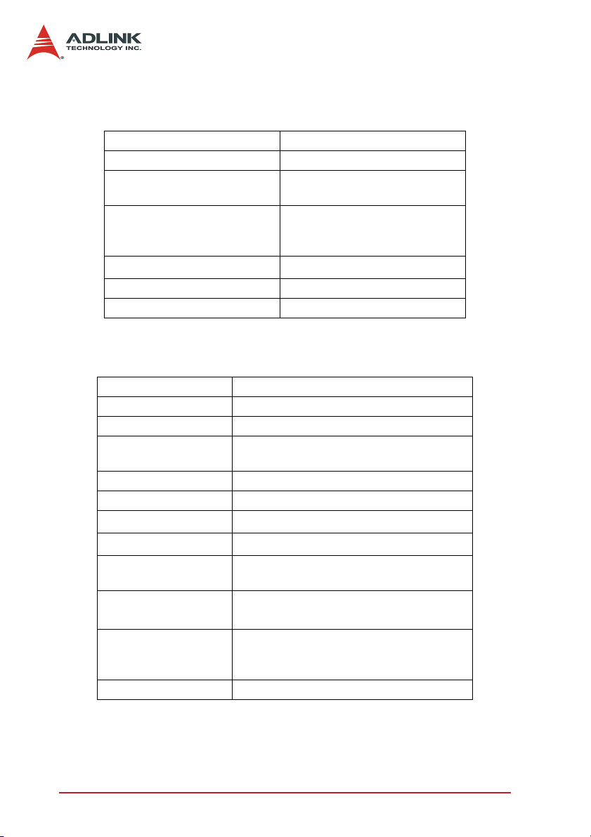
1.3 Specifications
Digital input
Input channels 8
Photo-coupler PC-3H4
Input current
Input Voltage
Input impedance
Input mode Isolation AC-filter/ Non-AC-filter
Isolated voltage 2,500 Vrms channel-to-system
Table 1-1: Digital Input Specifications
50 mA max. for isolated input
Relay Output
Output channels 8
Relay type 8 Non-latching SPST-NO + SPST-NC
Contact rating 250VAC, 5 A 30VDC, 5A
Breakdown voltage
Release time 10 ms max.
Operate time 10 ms max.
Contact resistance
Insulation resistance
Life expectancy
(min. operations)
Vibration Resistance
LED indicators
Power supply of Relay + 5V from the PCI-Bus
Table 1-2: Relay Output Specifications
1000 Vrms (open contacts), for 1 min
2000 Vrms (contacts and coil), for 1 min
1000MΩ min. (at 500 VDC)
> 5 X 10⁷ times Mechanical
> 105 times Electrical
176.4m/s
Monitor Contact/Open status of each
relay; external LED connectors could be
10 mA rated
Up-to 24 VDC or 24V AC
Logic Low: 0~2V
Logic High: 5~24V
4.7 KΩ
30m
Ω
2
(18G), 10 to 55Hz at double
amplitude of 3mm
applied
4Introduction
Page 15
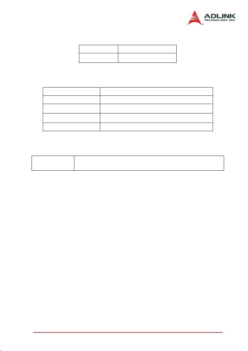
Isolated +5V Power Supply
Output Voltage +5V
Output Current
Table 1-3: Power Supply Specifications
170mA max. (@ 40°C)
General Specifications
Dimension 174.7 mm x 106.7 mm, standard PCI half size
Bus 32-bit PCI bus
Operating temperature
Storage temperature
Humidity 5 to 85% non-condensing
Table 1-4: General Specifications
0°C ~ 60°C
-40
°C ~ 80°C
Power Consumption
PCI-7260
+5V @ 510 mA typical
990mA maximum when all relays are acting simultaneously
Table 1-5: Power Consumption Specifications
Introduction 5
Page 16

1.4 Software Support
ADLINK provides versatile software drivers and packages for
users’ different approach to built-up a system. We provide not
only the programming library such as DLL for DOS and Windows,
but also drivers for many 3rd-party software packages. You may
find the programming library and 3rd-party software supports in
ADLINK All-in-One CD.
Programming Library
For customers who are writing their own programs with programming languages, we provide function libraries for different operating systems, including:
DOS libaray
Function libarary for DOS based on Turbo C. Please refer to
chapter 5 for descriptions of functions.
PCIS-DASK
Device driver and libarary packge for Windows 98/NT/2000/XP.
The PCIS-DASK is binary compatible across Windows 98, NT,
2000 and XP. That means all applications developed with
PCIS-DASK can be migrated to any Windows OS. The developing environment can be VB, VC++, Delphi, BC5, or any Windows programming language that allows DLL invokation. You
can find the driver package, user’s guide, and function reference of PCIS-DASK are in ADLINK All-in-One CD. Please refer
to the manuals in x:\Manual\Software Package\PCIS-DASK\
for more information. (x: denotes your CD-ROM drive)
DAQ-LVIEW PnP
DAQ-LVIEW PnP is the “Plug & Play” VI set to interface with
National Instruments LabVIEW under Windows 98/NT/2000/XP.
The DAQ-LVIEW PnP is free of charge and included in ADLINK
All-in-One CD. Please refer to the manuals in x:\Manual\Software
Package\DAQ-LVIEW PnP\ for more information. (x: denotes your
CD-ROM drive)
6Introduction
Page 17

2 Installation
This chapter outlines the contents of package, describes unpacking procedure, and describes how to install PCI-7260 into your
host system.
2.1 What you have
In addition to the User’s Manual, the package includes the following items:
X PCI-7260 non-latching relay and digital input cards
X ADLINK All-in-One CD
X This User’s Manual
If any of these items are missing or damaged, contact your
ADLINK dealer. Save the shipping materials and carton in to ship
or store the product in the future.
2.2 Unpacking
Your PCI-7260 card contains sensitive electronic components that
can be easily damaged by static electricity.
The card should be operated on a grounded anti-static mat. The
operator should be wearing an anti-static wristband, grounded at
the same point as the anti-static mat.
Inspect the card module carton for obvious damage. Shipping and
handling may cause damage to your module. Be sure there are no
shipping and handling damages on the module before processing.
After opening the card module carton, extract the system module
and place it only on a grounded antistatic surface with component
side up.
Again inspect the module for damage. Press down on all the
socketed IC's to make sure that they are properly seated. Do this
only with the module place on a firm flat surface.
Note: DO NOT APPLY POWER TO THE CARD IF IT HAS BEEN
Installation 7
DAMAGED.
You are now ready to install your PCI-7260.
Page 18
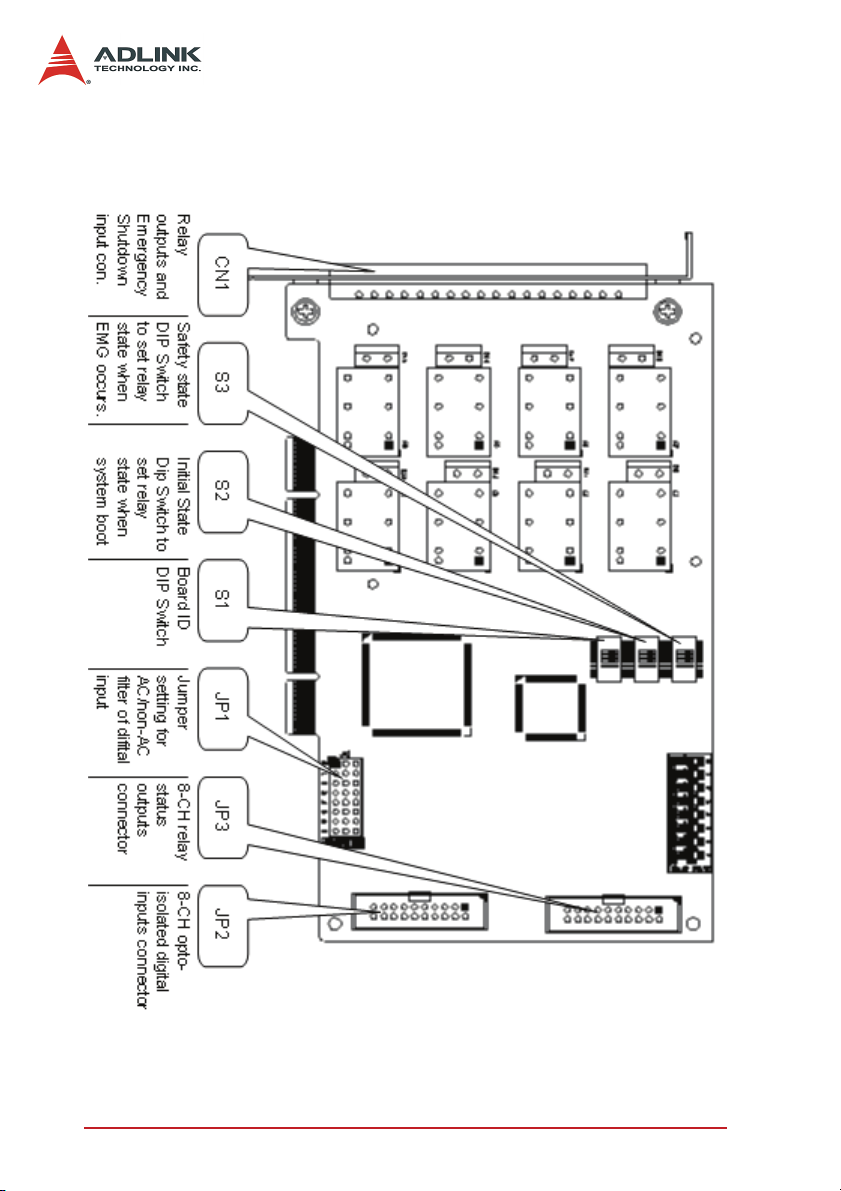
2.3 PCB Layout
The location of connectors, DIP switches and jumpers are shown
in Figure 2.1. They are described in the following sections.
Figure 2-1: PCI-7260 PCB Layout
8Installation
Page 19
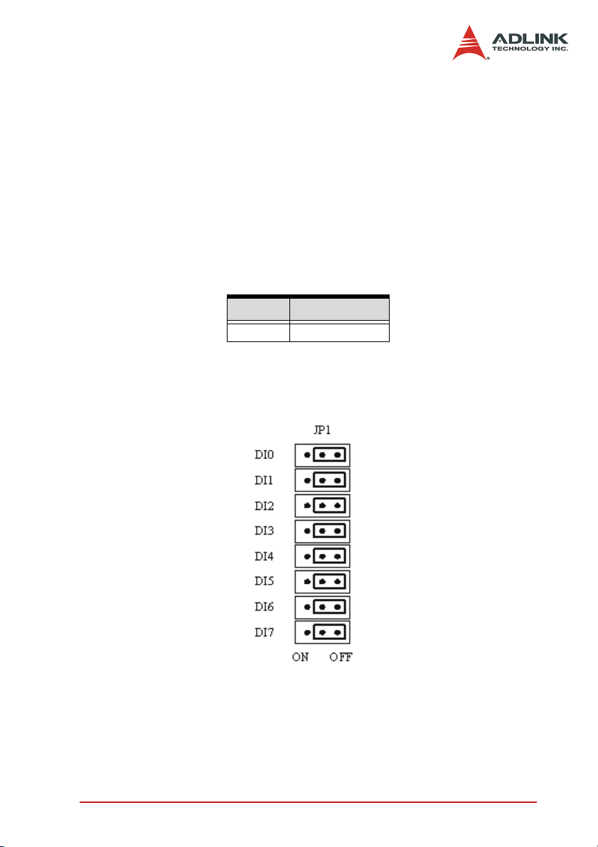
2.4 AC/non-AC filter setting (JP1)
The PCI-7260 is a ‘plug and play’ add-on card for PCI bus. It is not
necessary for user to setup its base address and IRQ level to fit
the hardware of your computer system. However, to fit user’s versatile operation, there are still a few jumpers to set for the digital
input.
The JP1 on PCI-7260 card are used to configure the digital input
channels as AC-Filtered or Non-AC-Filtered inputs. AC-filter is
used to filter unexpected noise in the digital signal. Each digital
input channel and its corresponding jumper are shown in the following Table2.1.
JUMPER INPUT SIGNAL
JP1 DI0 ~ DI7
Table 2-1: The jumpers and DI channels
The default setting of the input signal selection is Non-AC-Filtered
(DC signal input), which is shown as below :
Figure 2-2: Default Input Signal Jumper Setting
Installation 9
Page 20
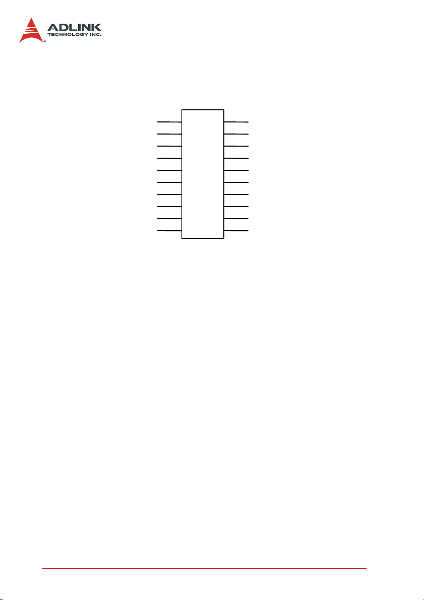
2.5 Isolated digital input connector (JP2)
DI 0+
DI 1+
DI 2+
DI 3+
DI 4+
DI 5+
DI 6+
DI 7+
GND
+5V
Figure 2-3: Isolated Digital Input Connector
The PCI-7260 card contains 8 opto-isolated digital input channels.
Utilizing the 20-pin ribbon connector (JP2) , users can connect
digital inputs to the isolated channels of PCI-7260.
Each row of JP2 corresponds to one of the eight DI channels. The
corresponding channel connection is shown in Figure 2.3. The digital input channels are isolated by photo couplers and accept
0~24V input voltage. The logic high is 5~24V and the logic low is
0~2V.
JP2
1 2
3 4
5 6
7 8
9 10
11 12
13 14
15 16
17 18
19 20
DI 0DI 1DI 2DI 3DI 4DI 5DI 6DI 7GND
+5V
10 Installation
Page 21

2.6 Relay status output connector (JP3)
EXT.LED 0EXT.LED 1EXT.LED 2EXT.LED 3EXT.LED 4EXT.LED 5EXT.LED 6EXT.LED 7-
Figure 2-4: Relay Status Output Connectors
The PCI-7260 card has 8 on-board LEDs to indicate the operation
status of the relay outputs. In addition, PCI-7260 also has 8 relay
status output channels for users who need external relay status
indicatros. Utilizing 20-pin ribbon connector(JP3) , users can have
their relays status shown outside the chassis. The relay status outputs support LEDs which have forward voltage (Vf) lower than 3V
and power consumption lower than 15mA. Each relay output
channel has a current limiting resistor (330O) connected with +5V
power, so users do not need to add a resistor to limit the current
flow through LED.
The direction of the external LED’s connection is shown in Figure
2.4. Before your connect LEDs on JP3 connectors, make sure the
LEDs are in the right direction.
JP3
1 2
3 4
5 6
7 8
9 10
11 12
13 14
15 16
17 18
19 20
A K
EXT.LED 0+
EXT.LED 1+
EXT.LED 2+
EXT.LED 3+
EXT.LED 4+
EXT.LED 5+
EXT.LED 6+
EXT.LED 7+
Installation 11
Page 22

2.7 Board ID (S1)
When users need more that two pieces of PCI-7260 plugged in
one host system, board ID is an effective mechanism to identity
the card. Users can set board ID to different PCI-7260 via the onboard DIP switch (S1) so that they can access the card correctly in
their programs. For more details about using Board ID in your program, please refer to Chapter 5.
Table 2.2 shows all conditions of the board ID setting .
Figure 2-5: Board ID setting
Board ID
01111 1
10111 1
21011 1
30011 1
41101 1
50101 1
……… ………… ………. ………….. ………… ……………
23 0 0 0 1 0
24 1 1 1 0 0
25 0 1 1 0 0
26 1 0 1 0 0
27 0 0 1 0 0
28 1 1 0 0 0
29 0 1 0 0 0
30 1 0 0 0 0
31 0 0 0 0 0
123 4 5
Table 2-2: Board ID Setting Conditions
Switch No.
Note: 1=on, 0=off
12 Installation
Page 23

2.8 Initial state DIP switch (S2)
When host system powers on, PCI-7260 will set the status of relay
outputs to the initial state set by initial state DIP switch (S2). When
the DIP switch is ON, the corresponding relay will be CLOSED
when power on. When the DIP switch is OFF, the corresponding
relay will be OPENED when power on. The default setting is ALL
OFF.
Figure 2-6: Initial State DIP Switch Setting
2.9 Emergency shutdown state DIP switch (S3)
When Emergency Shutdown input (from CN1) is set to HIGH, PCI7260 will switch the relay outputs to the state set by emergency
shutdown state DIP switch (S3). The transaction is done by onboard CPLD circuit and is irrelevant to host system. When the DIP
switch is ON, the corresponding relay will be CLOSED when
emergency shutdown. When the DIP switch is OFF, the corresponding relay will be OPENED when emergency shutdown. The
default setting is ALL OFF.
Figure 2-7: Emergency Shutdown State DIP Switch Setting
Installation 13
Page 24

2.10 Connector Pin Assignments (CN1)
The PCI-7260 card is equipped with a 18-pin pluggable connector
(CN1) on the front panel to provide relay outputs and emergency
shutdown input. The pin assignment of CN1 is described in Table
2-3.
NO0
COM0
NO1
COM1
NO2
COM2
NO3
COM3
NO4
COM4
NO5
COM5
NO6
COM6
NO7
COM7
EMG_SHDN+
EMG_SHDN-
Table 2-3: Pin Assignment of PCI-7260 CN1
Legend:
NO x Normal open pin of channel x, x=0~7
COM x Common pin of channel x, x=0~7
EMG_SHDN+ Emergency shutdown input +
EMG_SHDN- Emergency shutdown input -
14 Installation
Page 25

3 Register Format
The detailed descriptions of the register format are specified in this
chapter. This information is quite useful for the programmers who
want to handle the card by low-level programming. However, we
suggest user understand more about the PCI interface before
starting low-level programming.
Register Format 15
Page 26

3.1 I/O Address Map
The 7260 registers are all 16-bit wide. Users can access these
registers only by 16 bits I/O instructions. The control of the relays
and status of the isolation input is by means of accessing registers. The following table shows the register map, including
descriptions and their offset addresses relative to the base
address.
Offset Write Read
0x00h Relay Output CH. 0~7 Relay Output Read back CH.0~7
0x02h WDTimer Load Config
0x04h
0x06h COS Setup Register COS Latch Register
0x08h
0x0Ah --- Initial Dip Switch State
Emergency Shut Down Setup
Register (EMG_SHDN)
Interrupt / WDT Control
Register
Table 3-1: PCI-7260 Register Map
Emergency Shut Down Dip
Switch State
Isolated Input CH. 0~7
Interrupt / EMG_SHDN / WDT
Status Register
16 Register Format
Page 27

3.2 Relay Output Control Register
There are 8 non-latching relays on each PCI-7260 board. Each
non-latching relay is controlled by each bit of the control register.
The setting “1” means the non-latching relay is in RESET condition. Under the RESET condition, the normal open(NO) signal line
is ‘open’ from the common(COM) line and the normal close(NC)
signal line is connected with the common line. The setting “0”
means the normal open signal line is now closed, while the NC
signal is open.
For more information about the non-latching relay and software
function library, please refer to sections 4.1 and 5.3, respectively.
Address: BASE + 0x00
Attribute: Write
76543210
DO7DO6DO5DO4DO3DO2DO1DO0
15 14 13 12 11 10 9 8
--- --- --- --- --- --- --- ---
Register Format 17
Page 28

3.3 WDTimer Load Config Register
Watch Dog Timer Asynchronous load input. Asynchronously loads
the counter with the value on the data written in the follow
address. The corresponding hexadecimal value setted by user
determines WDTimer overflow time. The overflow time is calculated by the value that users set (Cnt_value) multiplied 1/2048 ms.
Address:BASE + 0x02
Attribute: Write
76543210
WDT
Data7
15 14 13 12 11 10 9 8
WDT
Data15
WDT
Data6
WDT
Data14
WDT
Data5
WDT
Data13
WDT
Data4
WDT
Data12
WDT
Data3
WDT
Data11
WDT
Data2
WDT
Data10
WDT
Data1
WDT
Data9
WDT
Data0
WDT
Data8
18 Register Format
Page 29

3.4 Relay Output Read Back Register
The status of the non-latching relay can be readback from the
readback register. If the relay is in RESET condition, the corresponding bit value is ‘0’. If the relay is in SET condition, the bit
value is ‘1’.
Address: BASE + 0x00
Attribute: Read
76543210
RBK7 RBK6 RBK5 RBK4 RBK3 RBK2 RBK1 RBK0
15 14 13 12 11 10 9 8
--- --- --- --- --- --- --- ---
RBKx: Read back data of relay x, x=0~7
1: relay is in SET status
0: relay is in RESET status
Register Format 19
Page 30

3.5 Emergency Shutdown Setup Register
The emergency shut down setup register allow user to enable or
disable the emergency stop function and clear EMG_SHDN status.
The default Emg_SHDN enable value is “1”. When The bit 0 value
“1” means the function is enable and “0” menas that is disable.
When Emergency Shutdown’s Input Pin (from the terminal connector) is one shot high, it will force PCI7260 enter the state of
“SHDN”( Relay Output pattern is determined on EMG_SHDN Dip
Swith(S3)). Whenever the users wants to control the relay output
by “Relay Output Control Register”, the relay pattern won’t
change until users acess the “EMG_SHDN Recovery bit”.
Address: BASE + 0x04
Attribute: Write
7 654321 0
Recovery --- --- --- --- --- --- EMG_EN
15 14 13 12 11 10 9 8
--- --- --- --- --- --- --- ---
EMG_EN: Emergengy shutdown enable
1: emergency shutdown is enable
0: emergency shutdown is disable
Recovery: Emergency shutdown status recovery
1: EMG SHDN Status is clear
0: No effects
20 Register Format
Page 31

3.6 Isolated Digital Input Register
There are 8 isolated input channels on PCI-7260 card. The status
of the 8 channels can be read from the isolated input register.
Each bit corresponds to each channel. The bit value “1” means the
input logic is high and “0” menas the input logic is low.
Address: BASE + 0x04
Attribute: Read
76543210
DI7 DI6 DI5 DI4 DI3 DI2 DI1 DI0
15 14 13 12 11 10 9 8
--- --- --- --- --- --- --- ---
DIx: isolated digiatal input channel x, x=0~7
1: input voltage is in high level
0: input voltage is in low level
Register Format 21
Page 32

3.7 COS Setup Register
The PCI-7260 provides a Change-of-State(COS) interrupt function
on any one of digital input channel. This function allows users to
monitor the status of input channels. By enabling the COS Setup
registers, it will generate an interrupt when the corresponding
channnel changes its state, whether a rising edge signal or a falling edge signal. For more detailed information, please refer to
Section 4.4.
Address: BASE + 0x06
Attribute: Write
76543210
COS
SET7
15 14 13 12 11 10 9 8
--- --- --- --- --- --- --- ---
COS
SET6
COS SETx: change-of-state setup of DI channel x,
COS
SET5
x=0 ~7
1: enable the COS interrupt
0: disable the COS interrupt
COS
SET4
COS
SET3
COS
SET2
COS
SET1
COS
SET0
22 Register Format
Page 33

3.8 COS Latch Register
When COS occurs, the COS Latch register will also latch the DI
data. Once the user clear the interrupt request, the COS Latch
register will be cleared automatically. The COS function releases
the CPU from the burden of polling all of the input channels, and
enables the computer to handle higher I/O performance.
Address: BASE + 0x06
Attribute: Read
76543210
CL7CL6CL5CL4CL3CL2CL1CL0
15 14 13 12 11 10 9 8
--- --- --- --- --- --- --- ---
CL x: COS latch register of DI channel x, x = 0 ~
7
1: digital input voltage is in high level
0: digital input voltage is in low level
Register Format 23
Page 34

3.9 Interrupt / WDT Control Register
There are three different interrupt modes in PCI-7260. In the first
mode, users enable the COS interrupt function to monitor the
enabled input channel’s status whenever the status changes from
0 to 1 or 1 to 0. In the second mode, users can select digital input
channel 0, channel 1 or both channels as the interrupt sources. In
this mode, interrupt only assertes when the DI status changes
from 0 to 1, i.e., rising edge. In the third mode, users can enable
WDTimer and let it count down. The interrupt assertes when
WDTimer is overflow. Because the three different modes share the
same interrupt signal in hardware, users are not allowed to enable
these tree modes at the same time.
After processing the interrupt request event, users have to clear
the interrupt request in order to handle another interrupt request.
To clear the interrupt request, write 1 to the corresponding bit.
Address: BASE + 0x08
Attribute: Write
7 6543 2 1 0
WDT CLR --- --- --- --- CH1 CLR CH0 CLR COS CLR
15 14 13 12 11 10 9 8
WDT Int_EN --- --- --- --- CH1 Int_EN CH0 Int_EN COS Int_EN
COS CLR (bit 0): write 1 to clear the COS
interrupt.
1 : clear the COS interrupt
0 : no effect
CH0 CLR (bit 1): write 1 to clear DI channel 0
interrupt.
1 : clear DI channel 0 interrupt
0 : no effect
CH1 CLR (bit 2): write 1 to clear DI channel 1
interrupt.
1 : clear DI channel 1 interrupt
0 : no effect
WDT CLR (bit 7): write 1 to clear WDT interrupt.
1 : clear WDT interrupt
0 : no effect
COS Int_EN (bit 8): Write/Read
Change-of-State interrupt enable control
24 Register Format
Page 35

1 : enable
0 : disable
CH0 Int_EN (bit 9): Write/Read
DI channel 0 interrupt enable control
1 : enable
0 : disable
CH1 Int_EN (bit 10): Write/Read
DI channel 1 interrupt enable control
1 : enable
0 : disable
WDT Int_EN (bit 15): Write/Read
WDTimer counter/interrupt enable control
1 : enable
0 : disable
The following table shows all possible combinations of interrupt
source.
Interurpt type Bit 15 Bit 10 Bit 9 Bit 8 IRQ source IRQ trigger condition
Disable 0 0 0 0 Interrupt disable --
Mode 1 0 0 0 1 COS interrupt
Mode 2 0 0 1 0
Mode 2 0 1 0 0
Mode 2 0 1 1 0
Mode 3 1 0 0 0
Forbidden X 0 1 1
Ch.0 interrupt
enable
Ch.1 interrupt
enable
Ch.0 & 1 interrupt
enable
WDTimer Couner
interrupt enable
Not allowed (dis-
able)
Change of state in
the enabled channel
Rising edge of DI
channel 0
Rising edge of DI
channel 1
Rising edge of DI
channel 0 or 1
WDTimer is overflow
---
Table 3-2: Interrupt Source Set Up
Register Format 25
Page 36

3.10 Interrupt / EMG_SHDN / WDT Status Register
When interrupt occurs, this register provides information for users
to recognize the interrupt status and the interrupt setup condition.
Address: BASE + 0x08
Attribute: Read
765 4 3 2 1 0
--- --- ---
15 14 13 12 11 10 9 8
--- --- ---
WDT Int
Status
WDT
Int_EN
COS Int. Status (bit 0): COS interrupt Status
register
0: COS interrupt de-asserts
1: COS interrupt asserts
CH0 Int. Status (bit 1): Digital input channel 0
interrupt status
0: Ch0 interrupt de-asserts
1: Ch0 interrupt asserts
CH1 Int. Status (bit 2): Digital input channel 1
interrupt status
0: Ch1 interrupt de-asserts
1: Ch1 interrupt asserts
EMG SHDN Status (bit 3): Emergency Shutdown
status
0: EMG_SHDN de-asserts
1: EMG_SHDN asserts
CH1 Int. Status (bit 4): WDTimer interrupt status
0: WDTimer interrupt de-asserts
1: WDTimer interrupt asserts
EMG SHDN
Status
EMG EN
CH1 Int.
Status
CH1
Int_EN
CH0 Int.
Status
CH0
Int_EN
COS Int.
Status
COS
Int_EN
26 Register Format
Page 37

3.11 Handling PCI Controller Registers
The PCI bus controller adopted in PCI-7260 is PCI-9030 which is
provided by PLX technology Inc. When users attempt to handle
low-level programming, some registers in PCI-9030 should be
noticed. The interrupt control register(INTCSR; 0x4Ch) of PCI9030 takes charge of all interrupt information from local bus to PCI
bus. When users want to develop their own interrupt function
driver, both interrupt registers in PCI-9030 and in PCI-7260 have
to work together. For more detailed information about the interrupt
control register in PCI-9030, please refer to the PCI-9030
databook.
In PCI-7260 software funciton library, we provide simple and easyto-use functions to handle the procedure of interrupt. Using these
functions, users don’t need to care about the interrupt register in
PCI controller. We suggest users use these functions instead of
developing interrupt functions by themselves. For more information about PCI-7260 funciton library, please refer to Chapter 5.
Register Format 27
Page 38

28 Register Format
Page 39

4 Operation Theorem
4.1 Non-Latching Relay Output
One of the innovative features on PCI-7260 is the 8-channel nonlatching relay output. The PCI-7260 contains only one type of nonlatching relay : 1 coil 1 Form A 1 Form B. Figure 4.1 shows the
latching relay contact arrangement under RESET condition.
Figure 4-1: 1 Coil Non-Latching Relay (RESET Condition)
Each non-latching relay on PCI-7260 has one coil which controls
each non-latching relay, we need only one control bit. What we
have to do is to energize and deenergize the coil when switching
RESET condition to SET condition. After the contact switches to
the opposite position at a steady state, we still cann’t cut out the
current on the coil and the contact will not change. Under the
scheme of controlling latching relay, we define the SET condition
control bit as “0” and the RESET condition control bit as “1”. For
more details about the non-latching relay control register, refer to
section 3.3.
PCI-7260 also provides a software function for user to control the
non-latching relays. Using this function, relay control is as simple
as the general relay. Instead of writing 32-bit data to the relay output register, user only needs to prepare 8-bit data and each bit
represents a relay’s status. Value ‘0’ represents SET condition
and value ‘1’ represents RESET condition. For more details about
the relay output function library, refer to section 5.3.
The relay output contacts are rated for a maximum of 5A at
250VAC (resistive), or 5A 30VDC. You should reduce these ratings for inductive loads. For more detailed information of relay
contact, please refer to Appendix A.
Operation Theorem 29
Page 40

4.2 Emergency Shutdown
In safety-critical applications, users can enable the emergency
shutdown function on PCI 7260, to manually set the relay pattern
to preset state. To access this function, users must first configure
the emergency shutdown function by On Board Switch. Generally
the trigger source is on the front panel and connected to a push
button, which pulls the SHDNn pin to logic-High when activated.
The trigger source can be routed through the Onboard Local Bus.
The default relay pattern for emergency shutdown is All-Off on
PCI-7260 switch; users can change the pattern by change the Dip
Switch. Upon receiving the emergency shutdown trigger, the
Switch Module enters shutdown mode, and the relay pattern is
switched to the preset state.
The Emergency Shutdown function operation flow is as follows:
1. Emergency Shutdown button one shot trigger as shown
in Figure 4.2
Figure 4-2: 7260 Card with EMG_SHDN Trigger
2. When the trigger is active, the relay output will change
corresponding to EMG_SHDN Dip Switch(S3)
3. When entering Emergency Shutdown state, users can
not access the relay output pattern until they clear the
state through function _7260_EMG_SETUP().
30 Operation Theorem
Page 41

4.3 Watchdog Timer
In safety-critical applications, users can enable the watchdog timer
function on PCI 7260 to automatically set the relay pattern to preset state, in case the operating system or PCI 7260 crashes. To
access this function, users must first configure the watchdog timer
overflow counter by windows API. Generally the trigger source
would come from the onboard 30-bit watchdog timer.
The watchdog timer overflow interval can be programmed through
Windows API. After enabling the watchdog timer, users must periodically reset the timer by software command. If the timer is not
being reset within the specified interval, the WDT module will generate an overflow signal and set the relay pattern to the one specified by users. This function is disabled by default. For more
information, please refer to the software programming users’
guide.
The Watch Dog Timer function operation flow is as follows:
1. Load the WDTimer counter value through the function
_7260_WDTimerSReload_Config(), this function allows
users to set WDTimer overflow time from 32 s to 2 ms.
2. Enable the WDTimer counter to count down through the
function _7260_INT_Control(), this function allows WDT
function in the CPLD (as Figure 4.3) starting to count
down. After enabling the function, users must reload
WDTimter by step (1) before it overflows. This makes
PCI-7260 work normally under WDT monitoring. When it
overflows, CPLD interrupt will occurs and emergency
shutdown will be active too to make relay output in a
safety pattern unless user disable the emergency shutdown function through function_7260_EMG_SETUP().
3. When WDTimer interrupt occurs, users must reload the
WDTimer through function
_7260_WDTimerSReload_Config() to clear WDTimer
carry out, and then clear the system interrupt through
function _7260_CLR_IRQ(). After doing this, the
WDTimer will count again unless user disable WDTimer
counter.
Operation Theorem 31
Page 42

Figure 4-3: CPLD with WDTimer Function
4.4 Isolated Digital Input
The PCI-7260 contains 8 opto-isolated digital input channels. The
circuit diagram of the isolated input channel is shown below.
Figure 4-4: Photo Coupler
The digital input is first routed through a photo-coupler (PC3H4),
so that the connection are not polarity sensitive whether using
positive or negative voltage.
In addition, a first order-filter with time constant about 1.5ms is
provided to filter high frequency noise. The normal input voltage
range for high state is 5 to 24V.
The PCI-7260 provides an isolated +5V power for dry contact
input. When the external circuit has no voltage source(e.g. a
switch), users can use the on board +5V to respond the change of
32 Operation Theorem
Page 43

external circuit. The maximum output current of the on board isolated power is 170mA (@40?). Please pay attention to the current
consumption of the external circuit not exceeding the limit. The dry
contact architecture is shown in Figure 4.3.
Figure 4-5: Dry contact
4.5 Interrupt Architecture
PCI-7260 has a powerful dual interrupt routing scheme including
change-of-state detection and interrupt sources on digital input
channel 0 and channel 1. Using these interrupts well can make
you handle more complicated information from outside enviroment
and release your computer from a heavy burden in dealing with
digital input data. Note that the dual interrupts do not mean the
card occupies two IRQ levels.
There are two interrupt modes in PCI-7260, but you can only
choose one of them at one time. Table3.2 shows all of the combinations of interrupt modes.
4.6 Change of State(COS) Interrupt
What is COS?
The COS (Change of State) means either the input state(logic
level) changes from low to high, or from high to low. The COS
detection circuit will detect the edge of level change. In the
PCI-7260 card, the COS detection circuit is applied to all the
input channels. When any channel changes its logic level, the
Operation Theorem 33
Page 44

COS detection circuit generates an interrupt request to PCI
controller.
COS Detection
The following timing is an example of COS operation. All of the
enabled DI channels’ signal level change will be detected to
generate the interrupt request.
While the interrupt request generates, the corresponding DI
data will also be latched into the COS latch register. In our COS
architecture, the DI data are sampled by a 8.25MHz clock. It
means the pulse width of the digital input have to last longer
than 122 ns, or the COS latch register won’t latch the correct
input data. The COS latch register will be erased after clearing
the interrupt request.
Figure 4-6: COS Timing
34 Operation Theorem
Page 45

5 C/C++ DOS Libraries
5.1 Programming Guide
Naming Convention
The functions of the NuDAQ PCI cards or NuIPC CompactPCI
cards’ software driver are using full-names to represent the functions' real meaning. The naming conventions are:
_{hardware_model}_{action_name}. e.g.
_7260_Initial().
All functions in the PCI-7260 drivers are with 7260 as
{hardware_model}.
Data Types
We have defined some data types in Pci_7260.h. These data
types are used by NuDAQ Cards’ library. We suggest you use
these data types in your application programs. The following table
shows the data type names and their range.
Typ e N ame Description Range
U8 8-bit ASCII character 0 to 255
I16 16-bit signed integer -32768 to 32767
U16 16-bit unsigned integer 0 to 65535
I32 32-bit signed integer -2147483648 to 2147483647
U32 32-bit single-precision floating-point 0 to 4294967295
F32 32-bit single-precision floating-point
F64 64-bit double-precision floating-point
Boolean Boolean logic value TRUE, FALSE
Table 5-1: Data Types
-3.402823E38 to
3.402823E38
-1.797683134862315E308 to
1.797683134862315E309
C/C++ DOS Libraries 35
Page 46

5.2 _7260 Initial
@ Description
The PCI-7260 cards are initialized according to the card number.
Because the PCI-7260 is PCI bus architecture and meets the plug
and play design, the IRQ and base_address ( pass-through
address) are assigned by system BIOS directly. Every PCI-7260
card has to be initialized by this function before using other functions.
@ Syntax
U16 _7260_Initial (U16 *existCards, PCI_INFO
*pciInfo)
@ Argument
existCards: The number of installed PCI-7260 cards. The
returned value shows how many PCI-7260 cards are installed in
your system.
pciInfo: It is a structure to memorize the PCI bus plug and play initiallization information which is decided by p&p BIOS. The
PCI_INFO structure is defined in ACL_PCI.H. The base I/O
address and the interrupt channel number is stored in pciinfo
which is for reference.
@ Return Code
ERR_NoError, ERR_PCIBiosNotExist,
ERR_BoardNoInit, ERR_InvalidBoardNumber
36 C/C++ DOS Libraries
Page 47

5.3 _7260_DO
@ Description
This function is used to write data to digital output port which can
energize the Non-latching relay coils. You can control all 8
RELAYs through _7260_DO by using this function. Althought the
register map of latching relays is 32 bit width, we use 8-bit access
to control the non-latching relay through this function. Bit ‘1’ represent the RESET condition, and Bit ‘0’ represent the SET condition.
@ Syntax
U16 _7260_DO (U16 boardID, U16 doData)
@ Argument
boardID: Board ID to the specific borad.
doData: value which will be written to digital output port.
@ Return Code
ERR_NoError, ERR_BoardNoInit
C/C++ DOS Libraries 37
Page 48

5.4 _7260_DO_Read_Back
@ Description
This function is used to read data back from digital output port control by 7260_DO function. There are 8-bit digital outputs on the
PCI-7260. You can get back all RELAYs status (SET or RESET)
by using this function.
@ Syntax
U16 _7260_DO_Read_Back (U16 boardID, U16
*DoReadBackData)
@ Argument
boardID: Board ID to the specific borad.
DoReadBackData: value read back from digital output port. ‘0’
represents the non-latching relay is under RESET condition and
‘1’ represents the non-latching relay is under SET condition.
@ Return Code
ERR_NoError, ERR_BoardNoInit
38 C/C++ DOS Libraries
Page 49

5.5 _7260_DI
@ Description
This function is used to read data from digital input port. There are
8-bit digital inputs on the PCI-7260. You can get all 8 input data by
using this function.
@ Syntax
U16 _7260_DI (U16 boardID, U16 *diData)
@ Argument
boardID: Board ID to the specific borad.
diData: return 8-bit value from digital input port.
@ Return Code
ERR_NoError, ERR_BoardNoInit
C/C++ DOS Libraries 39
Page 50

5.6 _7260_COS_Channel
@ Description
This function is used to enable the COS channel.
@ Syntax
U16 _7260_COS_Channel (U16 boardID, U16
COS_Enable_Data)
@ Argument
boardID: Board ID to the specific borad.
COS_Enable_Data: COS channel enable. ‘1’ enable the corre-
sponding channel and ‘0’ disable the corresponding channel.
@ Return Code
ERR_NoError, ERR_BoardNoInit
40 C/C++ DOS Libraries
Page 51

5.7 _7260_COS_Latch
@ Description
This function is used to latch digital input data after COS interrupt
occurs.
@ Syntax
U16 _7260_COS_Latch (U16 boardID, U16
*COS_Latch_Data)
@ Argument
boardID: Board ID to the specific borad.
COS_Latch_Data: Digital input data when COS occurs. This reg-
ister will be erased when clearing IRQ.
@ Return Code
ERR_NoError, ERR_BoardNoInit
C/C++ DOS Libraries 41
Page 52

5.8 _7260_INT_Control
@ Description
This function is used to control the interrupt source of PCI-7260.
For more details about interrupt sources, refer to section 3.7
@ Syntax
U16 _7260_INT_Control (U16 boardID, U16
COS_Enable, U16 CH0_Enable, U16 CH1_Enable,
U16 WDT_Enable)
@ Argument
boardID: Board ID to the specific borad.
COS_Enable: COS interrupt function enable/disable.
CH0_Enable: Digital input channel 0 interrupt enable/disable.
CH1_Enable: Digital input channel 1 interrupt enable/disable.
WDT_Enable: Watch Dog Timer interrupt counter enable/disable
The possible combinations of interrupt source are shown in the following table.
WDT_Enable CH1_Enable CH0_Enable COS_Enable
0000
0001
0010
0100
0110
1000
42 C/C++ DOS Libraries
IRQ
source
Interrupt
disable
COS inter-
rupt
Ch.0 inter-
rupt enable
Ch.1 inter-
rupt enable
Ch.0 & 1
interrupt
enable
WDT inter-
rupt enable
IRQ trigger condition
--
Change of state in the
enabled channel
Rising edge of DI
channel 0
Rising edge of DI
channel 1
Rising edge of DI
channel 0 & 1
Rising edge of WDT
carry out overflow
Page 53

WDT_Enable CH1_Enable CH0_Enable COS_Enable
01
X
10
1
@ Return Code
ERR_NoError, ERR_BoardNoInit, ERR_INTNotSet
IRQ
source
Not allowed
(disable
IRQ trigger condition
---10
C/C++ DOS Libraries 43
Page 54

5.9 _7260_CLR_IRQ
@ Description
This function is used to clear the interrupt request of PCI-7260.
@ Syntax
U16 _7260_CLR_IRQ (U16 boardID, U16 COS_CLR, U16
CH0_CLR, U16 CH1_CLR, U16 WDT_CLR)
@ Argument
boardID: Board ID to the specific borad.
COS_CLR: Clear COS interrupt request.
CH0_CLR: Clear digital input channel 0.
CH1_CLR: Clear digital input channel 1.
WDT_CLR: Clear Watch Dog Timer interrupt request.
@ Return Code
ERR_NoError, ERR_BoardNoInit
44 C/C++ DOS Libraries
Page 55

5.10 _7260_GET_IRQ_Status
@ Description
This function is used to get the interrupt status of PCI-7260.
@ Syntax
U16 _7260_GET_IRQ_Status (U16 boardID, U16
*COS_Status, U16 *CH0_Status, U16
*CH1_Status, U16 *EMG_SHDN_Status, U16
*WDT_Status)
@ Argument
boardID: Board ID to the specific borad.
COS_Status: COS interrupt status.
X ‘1’ represents interrupt asserts.
X ‘0’ represents interrupt de-asserts.
CH0_Status: Digital input channel 0 interrupt status. ‘1’ represents
interrupt asserts.
X ‘0’ represents interrupt de-asserts.
CH1_Status: Digital input channel 1 interrupt status. ‘1’ represents
interrupt asserts.
X ‘0’ represents interrupt de-asserts.
EMG_SHDN_Status: Emergency Shutdown status.
X ‘1’ represents EMG SHDN asserts.
X ‘0’ represents EMG SHDN de-asserts.
WDT_Status: Watch Dog Timer interrupt status.
X ‘1’ represents interrupt asserts.
X ‘0’ represents interrupt de-asserts.
@ Return Code
ERR_NoError, ERR_BoardNoInit
C/C++ DOS Libraries 45
Page 56

5.11 _7260_WDTimerSReload_Config
@ Description
This function is used to clear the WDTimer overflow state of PCI7260 and reload the count value.
@ Syntax
U16 _7260_ WDTimerSReload_Config (U16 boardID,
Int WDT_CountData)
@ Argument
boardID: Board ID to the specific borad.
WDT_CountData: decimal value from 2 (ms) to 31999 (ms) which
will be written to WDT reload value.
@ Return Code
ERR_NoError, ERR_BoardNoInit
46 C/C++ DOS Libraries
Page 57

5.12 _7260_EMG_SETUP
@ Description
This function is used to enable/disable the emergency stop function of PCI-7260.
@ Syntax
U16 _7260_EMG_EN (U16 cardNo,U16
EMG_EN_BUTTON,U16 EMG_Recovery)
@ Argument
boardID: Board ID to the specific borad.
EMG_EN_BUTTON: Emergency Stop enable/disable. ‘1’ repre-
sents EMG enable. ‘0’ represents EMG disable.
EMG_Recovery: Emergency Stop status recovery. ‘1’ represents
EMG state clear. ‘0’ has no effect.
@ Return Code
ERR_NoError, ERR_BoardNoInit
C/C++ DOS Libraries 47
Page 58

5.13 _7260_EmgShdnDipSwitch_status
@ Description
This function is used to read data from emergency shutdown dip
switch. There are 8-bit digital inputs on the Emergency shutdown
dip switch. You can get all 8 input data by using this function.
@ Syntax
U16 _7260_EmgShdnDipSwitch_status (U16 boardID, U16
*diData)
@ Argument
boardID : Board ID to the specific borad.
diData :return 8-bit value from emergency shutdown dip switch.
@ Return Code
ERR_NoError, ERR_BoardNoInit
48 C/C++ DOS Libraries
Page 59

5.14 _7260_InitDipSwitch_status
@ Description
This function is used to read data from initial state dip switch.
There are 8-bit digital inputs on the Initial State dip switch. You can
get all 8 input data by using this function.
@ Syntax
U16 _7260_DI (U16 boardID, U16 *diData)
@ Argument
boardID: Board ID to the specific borad.
diData: return 8-bit value from initial state dip switch.
@ Return Code
ERR_NoError, ERR_BoardNoInit
C/C++ DOS Libraries 49
Page 60

50 C/C++ DOS Libraries
Page 61

6 Appendix
6.1 Relay Contact Protection Circuits
The contacts are the most important elements of relay constructions, Contact performance is conspicuously influenced by contact
material, voltage and current values applied to the contacts.
Another important issue is contact protection, a right contact protection circuit can suppress the counter EMF to a low level. However, note that incorrect use will result in an adverse effect. Typical
contact protection circuits are given below :
RC Circuit
This circuit is suitable for DC application. If the load is a timer,
leakage current flows through the RC circuit causing faulting operation.
Contact
RC
Inductive
Load
The below circuit is suitable for both AC and DC applications. If
the load is a relay or solenoid, the release time lengthens. It’s
effective when connected to both contacts if the power supply voltage is 24V or 48V and the voltage cross the load is 100 to 200V.
Device Selection:
As a guide in selecting R and C,
Z R : 0.5 to 1Ω per 1V contact voltage
Z C : 0.5 to 1μF per 1A contact current
Values vary depending on the properties of the capacity C acts to
suppress the discharge the moment the contacts open. Resistor R
acts to limit the current when the power is turned on the next time.
Appendix 51
Page 62

Test to confirm. Use a capacitor with a breakdown voltage of 200
to 300V. Use AC type capacitors (non-polarized) for AC circuits.
Diode Circuit
This circuit is suitable for DC application. The diode connected in
parallel causes the energy stored in the coil to flow to the coil in
the form of current and dissipates it as joule heat at the resistance
component of the inductive load. This circuit further delays the
release time compared to the RC circuit.
Contact
Diode
Inductive
Load
Device Selection:
Use a diode with a reverse breakdown voltage at least 10 times
the circuit voltage and a forward current at least as large as the
load current. In electronic circuits where the circuit voltages
reverse breakdown voltage of above 2 to 3 times the power
supply voltage.
Diode & Zener diode Circuit
This circuit is also suitable for DC application. Effective when the
release time i the diode circuit is too long.
Contact
Diode
Inductive
Load
52 Appendix
Page 63

Device Selection:
Use a zener diode with a zener voltage about the same as the
power supply voltage.
Varistor Circuit
This circuit is also suitable for both AC & DC applications. Using
the stable voltage characteristics of the varistor, this circuit prevents excessively high voltages from being applied across the
contacts. This circuit also slightly delays the release time. Effective
when connected to both contacts of the power supply voltage is 24
or 48V and the voltage across the load is 100 to 200 V.
Contact
Diode
Inductive
Load
Appendix 53
Page 64

54 Appendix
Page 65

Warranty Policy
Thank you for choosing ADLINK. To understand your rights and
enjoy all the after-sales services we offer, please read the following carefully.
1. Before using ADLINK’s products please read the user manual and follow the instructions exactly. When sending in
damaged products for repair, please attach an RMA application form which can be downloaded from: http://
rma.adlinktech.com/policy/.
2. All ADLINK products come with a limited two-year warranty, one year for products bought in China:
X The warranty period starts on the day the product is
shipped from ADLINK’s factory.
X Peripherals and third-party products not manufactured
by ADLINK will be covered by the original manufacturers' warranty.
X For products containing storage devices (hard drives,
flash cards, etc.), please back up your data before sending them for repair. ADLINK is not responsible for any
loss of data.
X Please ensure the use of properly licensed software with
our systems. ADLINK does not condone the use of
pirated software and will not service systems using such
software. ADLINK will not be held legally responsible for
products shipped with unlicensed software installed by
the user.
X For general repairs, please do not include peripheral
accessories. If peripherals need to be included, be certain to specify which items you sent on the RMA Request
& Confirmation Form. ADLINK is not responsible for
items not listed on the RMA Request & Confirmation
Form.
Warranty Policy 55
Page 66

3. Our repair service is not covered by ADLINK's guarantee
in the following situations:
X Damage caused by not following instructions in the
User's Manual.
X Damage caused by carelessness on the user's part dur-
ing product transportation.
X Damage caused by fire, earthquakes, floods, lightening,
pollution, other acts of God, and/or incorrect usage of
voltage transformers.
X Damage caused by unsuitable storage environments
(i.e. high temperatures, high humidity, or volatile chemicals).
X Damage caused by leakage of battery fluid during or
after change of batteries by customer/user.
X Damage from improper repair by unauthorized ADLINK
technicians.
X Products with altered and/or damaged serial numbers
are not entitled to our service.
X This warranty is not transferable or extendible.
X Other categories not protected under our warranty.
4. Customers are responsible for shipping costs to transport
damaged products to our company or sales office.
5. To ensure the speed and quality of product repair, please
download an RMA application form from our company website: http://rma.adlinktech.com/policy. Damaged products
with attached RMA forms receive priority.
If you have any further questions, please email our FAE staff:
service@adlinktech.com.
56 Warranty Policy
 Loading...