

Page 1
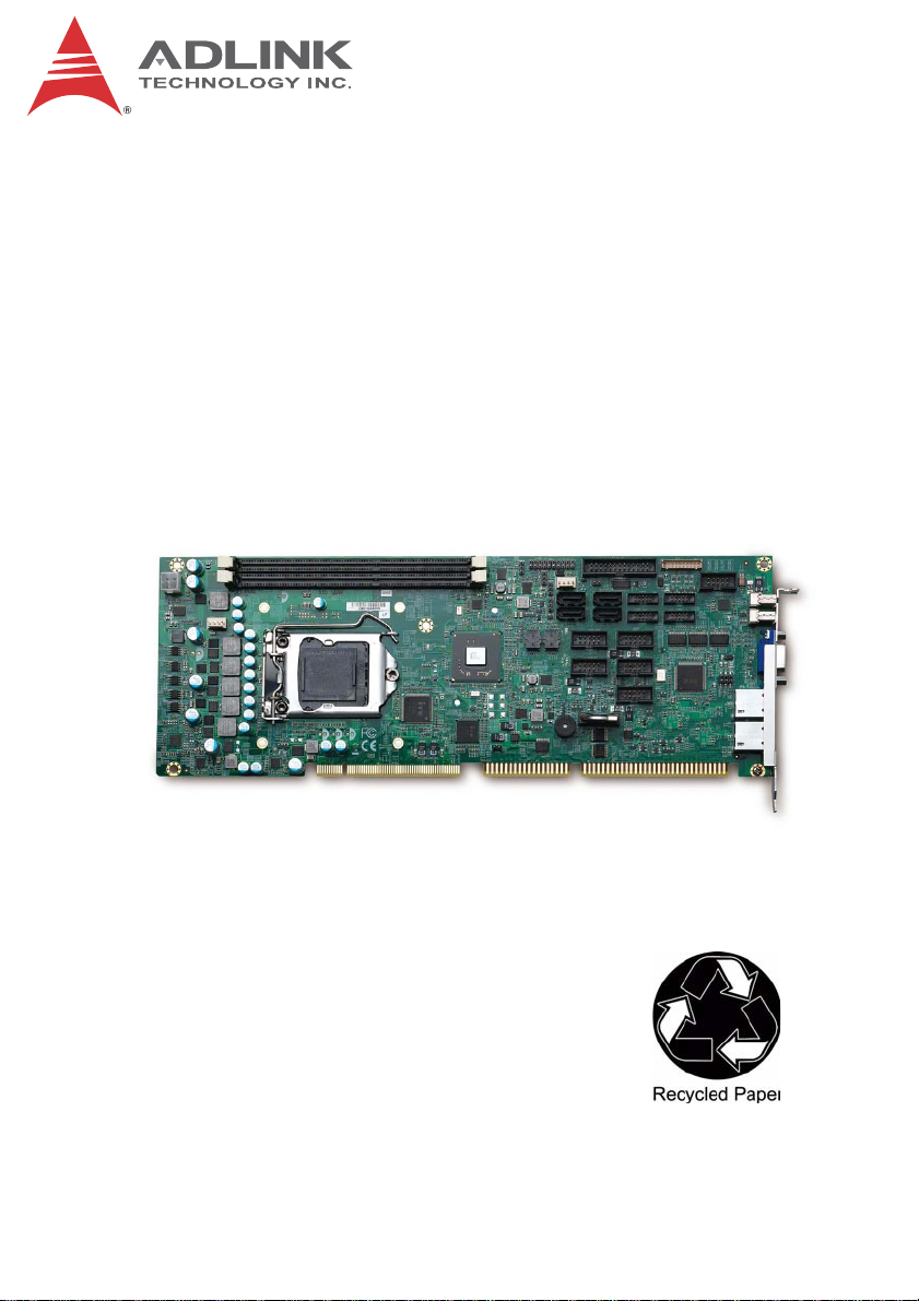
NuPRO-A40H
Full-Size PICMG 1.0 Intel® Core™ i7/i5/i3
LGA1155 SHB
User’s Manual
Manual Rev.: 2.00
Revision Date: September 11, 2013
Part No: 50-13072-1010
Advance Technologies; Automate the World.
Page 2

Revision History
Revision Release Date Description of Change(s)
1.00 2013/07/19 Preliminary release
2.00 2013/09/11
Initial release (add BIOS, WDT, system
resources)
ii Revision History
Page 3

NuPRO-A40H
Preface
Copyright 2013 ADLINK Technology, Inc.
This document contains proprietary information protected by copyright. All rights are reserved. No part of this manual may be reproduced by any mechanical, electronic, or other means in any form
without prior written permission of the manufacturer.
Disclaimer
The information in this document is subject to change without prior
notice in order to improve reliability, design, and function and does
not represent a commitment on the part of the manufacturer.
In no event will the manufacturer be liable for direct, indirect, special, incidental, or consequential damages arising out of the use or
inability to use the product or documentation, even if advised of
the possibility of such damages.
Environmental Responsibility
ADLINK is committed to fulfill its social responsibility to global
environmental preservation through compliance with the European Union's Restriction of Hazardous Substances (RoHS) directive and Waste Electrical and Electronic Equipment (WEEE)
directive. Environmental protection is a top priority for ADLINK.
We have enforced measures to ensure that our products, manufacturing processes, components, and raw materials have as little
impact on the environment as possible. When products are at their
end of life, our customers are encouraged to dispose of them in
accordance with the product disposal and/or recovery programs
prescribed by their nation or company.
Trademarks
Product names mentioned herein are used for identification purposes only and may be trademarks and/or registered trademarks
of their respective companies.
Preface iii
Page 4

Using this Manual
Audience and Scope
The NuPRO-A40H User’s Manual is intended for hardware
technicians and systems operators with knowledge of installing,
configuring and operating industrial grade single board computers.
Manual Organization
This manual is organized as follows:
Preface: Presents important copyright notifications, disclaimers,
trademarks, and associated information on the proper understanding and usage of this document and its associated product(s).
Chapter 1, Introduction: Introduces the NuPRO-A40H, its fea-
tures, applications, and specifications, including functional
descriptions and board layout.
Chapter 2, Hardware Information: Provides technical informa-
tion on connectors and jumpers for configuring the NuPRO-A40H.
Chapter 3, Getting Started: Illustrates how to install components
on the NuPRO-A40H such as CPU, heatsink, and memory modules.
Chapter 4, Driver Installation: Provides information on how to
install the NuPRO-A40H device drivers.
Chapter 5, BIOS Setup: Describes basic navigation for the
AMIBIOS®8 BIOS setup utility.
Appendix A, Watchdog Timer: Presents information on imple-
menting the watchdog timer.
Appendix B, System Resources: Presents information on I/O
mapping, IRQ routing, and resource allocation.
Important Safety Instructions: Presents safety instructions all
users must follow for the proper setup, installation and usage of
equipment and/or software.
Getting Service: Contact information for ADLINK’s worldwide
offices.
iv Preface
Page 5

NuPRO-A40H
Conventions
Take note of the following conventions used throughout this
manual to make sure that users perform certain tasks and
instructions properly.
Additional information, aids, and tips that help users perform
tasks.
NOTE:
NOTE:
Information to prevent minor physical injury, component dam-
age, data loss, and/or program corruption when trying to com-
CAUTION:
WARNING:
plete a task.
Information to prevent serious physical injury, component
damage, data loss, and/or program corruption when trying to
complete a specific task.
Preface v
Page 6

This page intentionally left blank.
vi Preface
Page 7

NuPRO-A40H
Table of Contents
Revision History...................................................................... ii
Preface.................................................................................... iii
List of Figures........................................................................ xi
List of Tables........................................................................ xiii
1 Introduction ........................................................................ 1
1.1 Overview.............................................................................. 1
1.2 Features............................................................................... 2
1.3 Specifications....................................................................... 3
1.4 Block Diagram ..................................................................... 5
1.5 Functional Description ......................................................... 6
1.6 Mechanical Drawing ............................................................ 8
1.7 I/O Connectivity ................................................................... 9
1.8 Power Consumption .......................................................... 10
1.9 Package Contents ............................................................. 11
2 Hardware Information...................................................... 13
2.1 Rear Panel I/O Ports.......................................................... 13
2.2 Board Layout ..................................................................... 15
2.3 Onboard Connectors ......................................................... 16
2.4 Jumpers ............................................................................. 24
3 Getting Started ................................................................. 27
3.1 Installing the CPU .............................................................. 27
3.2 Installing the CPU Fan and Heatsink................................. 31
3.3 Installing Memory Modules ................................................ 32
3.4 Installing the Power Connectors ........................................ 34
Table of Contents vii
Page 8

4 Driver Installation.............................................................. 35
4.1 Chipset Driver .................................................................... 35
4.2 Display Driver..................................................................... 35
4.3 Ethernet Driver................................................................... 36
4.4 Audio Driver ....................................................................... 36
5 BIOS Setup........................................................................ 37
5.1 Starting the BIOS ............................................................... 37
5.2 Main Setup......................................................................... 41
5.3 Advanced BIOS Setup ....................................................... 43
5.3.1 ACPI Settings ................................................................ 44
5.3.2 CPU Configuration......................................................... 45
5.3.3 SATA Configuration ....................................................... 47
5.3.4 USB Configuration ......................................................... 48
5.3.5 Super IO Configuration .................................................. 50
5.3.6 Serial Port Console Redirection..................................... 51
5.3.7 CPU PPM Configuration ................................................ 55
5.4 Chipset Setup .................................................................... 56
5.4.1 PCH-IO Configuration.................................................... 57
5.4.2 System Agent (SA) Configuration.................................. 60
5.5 Boot Configuration ............................................................. 63
5.6 Security Setup.................................................................... 66
5.7 System Management ......................................................... 68
5.8 Exit Menu ........................................................................... 69
A Appendix: Watchdog Timer..............................................71
A.1 Sample Code ..................................................................... 71
B Appendix: System Resources..........................................75
B.1 System Memory Map ......................................................... 75
B.2 Direct Memory Access Channels....................................... 75
B.3 IO Map ............................................................................... 76
B.4 Interrupt Request (IRQ) Lines............................................ 77
viii Table of Contents
Page 9

NuPRO-A40H
Important Safety Instructions.............................................. 83
Getting Service...................................................................... 85
Table of Contents ix
Page 10

This page intentionally left blank.
xTable of Contents
Page 11

NuPRO-A40H
List of Figures
Figure 1-1: NuPRO-A40H Block Diagram .......................................... 5
Figure 1-2: NuPRO-A40H Board Dimensions .................................... 8
Figure 2-1: Rear Panel I/O Ports...................................................... 13
Figure 2-2: Connectors and Jumpers............................................... 15
List of Figures xi
Page 12

This page intentionally left blank.
xii List of Figures
Page 13

NuPRO-A40H
List of Tables
Table 1-1: NuPRO-A40H I/O Connectivity........................................ 9
Table 1-2: Core™ i7-3770 Processor Power Consumption............ 10
Table B-1: System Memory Map..................................................... 75
Table B-2: Direct Memory Access Channels................................... 75
Table B-3: IO Map........................................................................... 77
Table B-4: IRQ Lines PIC Mode...................................................... 78
Table B-5: IRQ Lines APIC Mode ................................................... 79
Table B-6: PCI Configuration Space Map ....................................... 80
Table B-7: PCI Interrupt Routing Map............................................. 81
List of Tables xiii
Page 14

This page intentionally left blank.
xiv List of Tables
Page 15

NuPRO-A40H
1 Introduction
1.1 Overview
The ADLINK NuPRO-A40H is a PICMG 1.0 Single Board
Computer (SBC) supporting the 3rd generation Intel®
Core™ i7/i5/i3 and Pentium® processors in LGA1155 package to
deliver a scalable high performance platform for a wide array of
industrial applications. The NuPRO-A40H supports 22nm process
CPUs at up to 3.4 GHz with integrated graphics and memory
controllers, Direct Media Interface (DMI) and Flexible Display
Interface (FDI) connectivity to the Intel® H61 Express Chipset.
Dual-channel DDR3 1333/1600 MHz memory is supported up to a
maximum of 16GB in two DIMM slots.
These advanced features, coupled with dual PCI Express®-based
Gigabit Ethernet, SATA 3 Gb/s and USB 2.0 support make the
NuPRO-A40H ideal for automation control applications.
Introduction 1
Page 16

1.2 Features
X Supports 3rd Generation Intel® Core™ i7/i5/i3, and Pen-
tium® processors in LGA1155 package
X Integrated Intel® HD Graphics with VGA and DVI-D output
X Dual Gigabit Ethernet
X 8x USB 2.0 ports (2x faceplate, 6x onboard pin headers)
X 4x SATA 3 Gb/s ports
X 6x COM ports (including 1x RS-232/422/485 with auto flow
control)
X Watchdog Timer, Hardware Monitor
X Optional HD audio kit (DB-Audio2 daughter board)
X RoHS compliant
To purchase the optional DB-Audio2 daughter board, please
contact your ADLINK sales representative.
NOTE:
NOTE:
2Introduction
Page 17

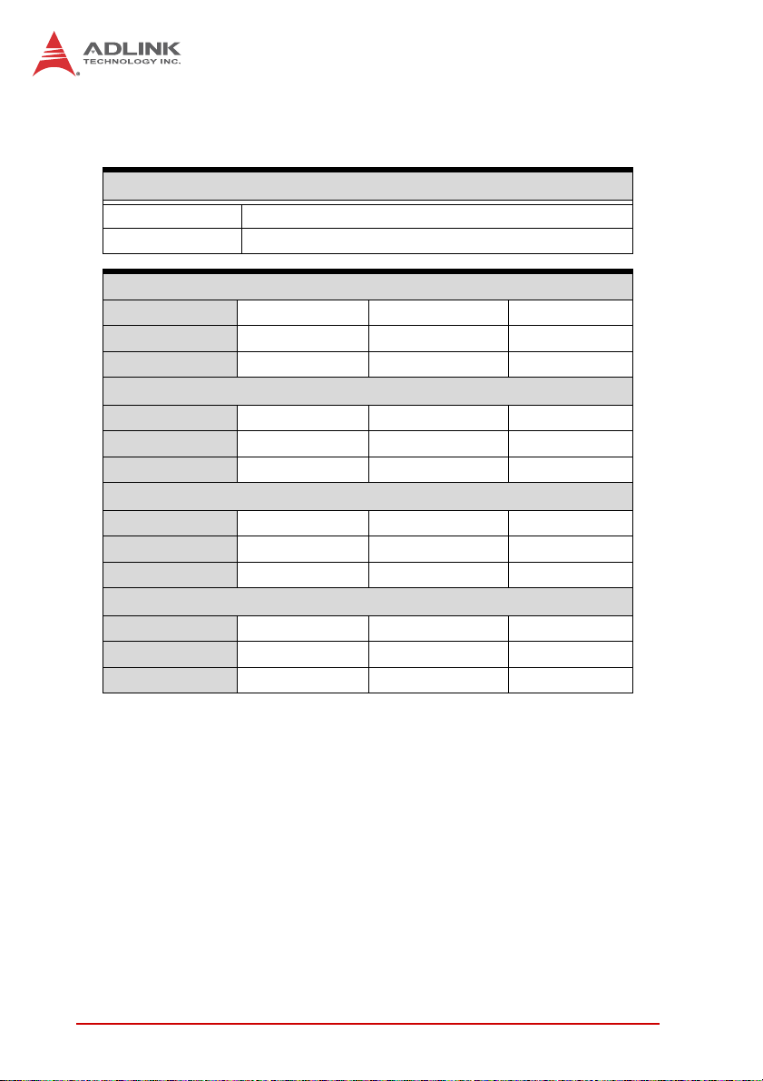
1.3 Specifications
System
3rd Gen Intel® Core™ processors in LGA1155 package:
• Intel® Core™ i7-3770, 3.4 GHz, 8M Cache, 22nm, 95W
CPU
Chipset • Intel® H61 Platform Controller Hub
Memory
BIOS • AMI BIOS in 64-Mbit SPI Flash
Audio
Watch Dog Timer
Hardware
Monitor
Operating
Systems
Serial ATA • 4x SATA 3 Gb/s ports onboard
I/O Ports
Expansion
Integrated
Graphics
• Intel® Core™ i5-3550, 3.0 GHz, 6M Cache, 22nm, 95W
• Intel® Core™ i3-3220, 3.3 GHz, 3M Cache, 22nm, 65W
• Intel®
• Two 240-pin DIMM sockets support dual-channel
• Intel® High Definition Audio support via DB-Audio2
• 1-255 second/minute programmable and can generate
• CPU/System temperature, fan speed and onboard DC
• Windows® XP, Windows® 7, 32/64-bit;
• 2x USB 2.0 port on rear panel, 6x via onboard header
• 6x serial ports via onboard pin-header
• 2x GbE RJ-45 ports
• VGA port (Dsub-15)
• DVI-D (onboard header)
• PS/2 Keyboard/Mouse (onboard header)
• 1 Parallel port (onboard header)
• PCI 32-bit/33MHz, PCIe-to-PCI Bridge: ITE IT8892E
• PCI-to-ISA Bridge: ITE IT8888G (DMA not supported)
• Integrated Intel® HD Graphics on processor
• VGA: to 2048x 1536 @ 75 Hz
• DVI: 1x internal pin header
Pentium® G2120, 3.1 GHz, 3M Cache, 22nm, 55W
1333/1600 MHz DDR3 (up to 16GB)
daughter board
system reset.
voltage by ADLINK Smart Embedded Management
Agent (SEMA)
Fedora™ 17, Red Hat Enterprise Linux
I/O Interfaces
(5x RS-232; 1x RS-232/422/485 with auto flow control,
BIOS selectable)
Display
NuPRO-A40H
Introduction 3
Page 18
Ethernet
• Dual Intel® I211-AT Gigabit Ethernet Controller
Controller
Ports • Two RJ-45 Ethernet ports
Form Factor • Standard full-size PICMG 1.0 SBC
Dimensions • 338 x 122 mm (L x W)
Operating Temp. • 0ºC to 60ºC
Storage Temp. • -20ºC to 80ºC
Relative Humidity • 10% to 90% non-condensing
Safety • CE, FCC Class A
• Supports Preboot Execution Environment (PXE),
Wake-On-LAN, 9KB Jumbo Frames
Mechanical and Environment
4Introduction
Page 19
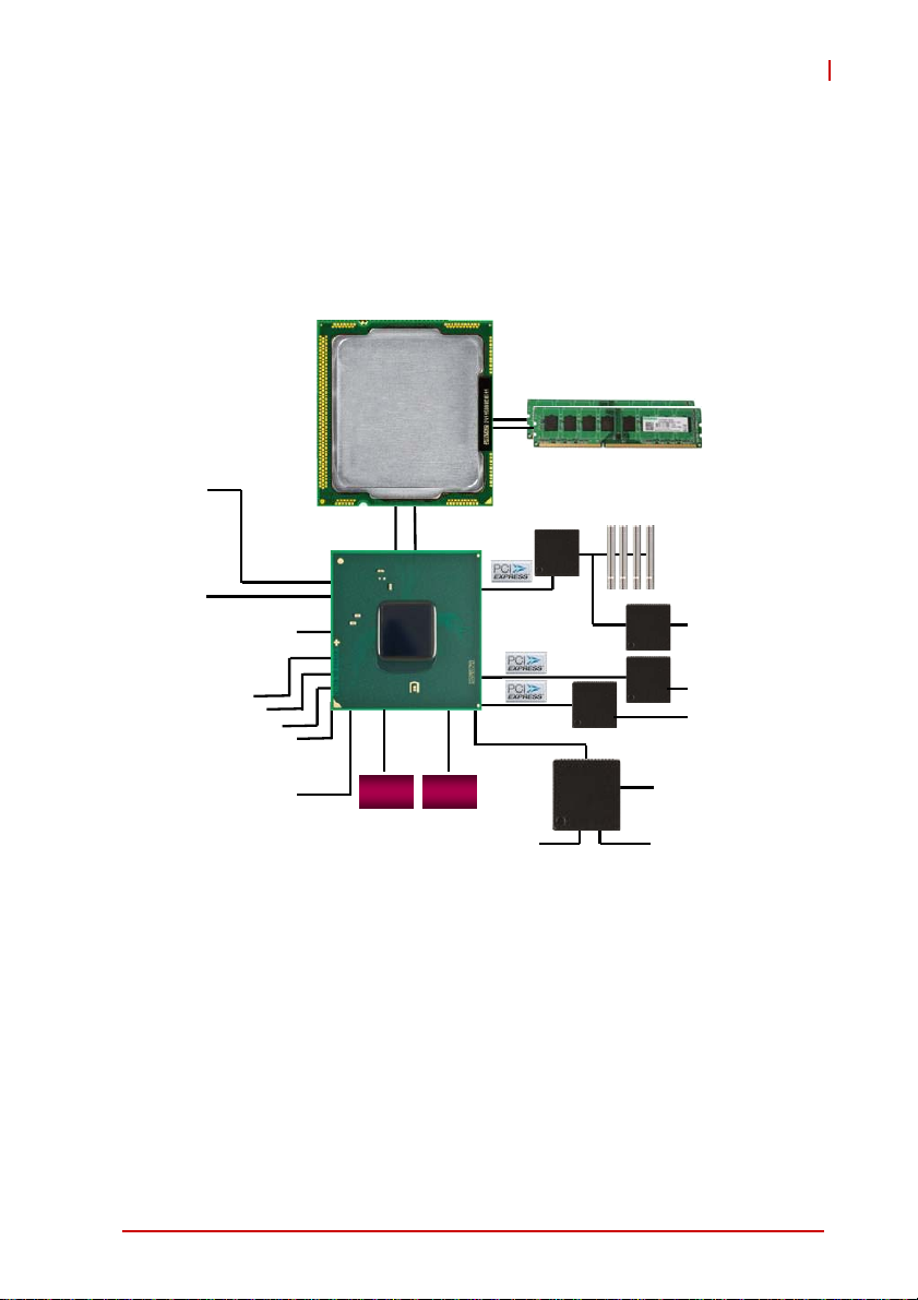
1.4 Block Diagram
NuPRO-A40H
VGA
DVI-D
8 USB 2.0 Ports
4 SATA Ports
at 3.0Gb/s
Audio
Dual Channel
DDR3 1333/1600
Max. 16GB
PCIe to
PCI
Bridge
Intel
LPC
I211-AT
Super
I/O
PCI to
ISA
Bridge
Intel
I211-AT
Intel Core
Intel Core
dual/quad
dual/quad
32/22nm
32/22nm
x2 Display Link
3rd Gen
3rd Gen
i7/i5/i3
i7/i5/i3
core
core
x4 DMI
Intel
Intel
H61
H61
PCH
PCH
SPI
LEMT
BIOS
Pin Header
for KB/MS
Figure 1-1: NuPRO-A40H Block Diagram
PCI Bus
(4x Master)
ISA Bus
Dual
GbE
6 COM
LPT
Introduction 5
Page 20

1.5 Functional Description
Processor Support
The NuPRO-A40H is PICMG 1.0 Single Board Computer supporting the 3rd Generation Intel® Core™ processor family (Intel®
Core™ i7/i5/i3, Pentium®) in LGA1155 socket. An integrated
memory controller supports dual channel 1333/1600 MHz DDR3
and Intel® HD Graphics is integrated onboard the CPU. Direct
Media Interface (DMI) and Flexible Display Interface (FDI) provide
connectivity to the Intel® H61 Express Chipset.
Intel® H61 Express Chipset
The Intel® BD82H61 Platform Controller Hub (PCH) combines
with the processor to provide a compact yet powerful 2-chip solution. Direct Media Interface (DMI) is the chip-to-chip connection
between the processor and PCH. Intel® Flexible Display Interface
carries display traffic from the integrated graphics in the processor
to the legacy display connectors in the PCH. The PCH supports all
other required interfaces including PCI Express, SATA 3 Gb/s,
USB 2.0, LPC, and SPI.
Dual-Channel DDR3 Memory
To meet the requirements of memory-intensive applications, the
NuPRO-A40H has a dual-channel memory architecture supporting
DDR3 1333/1600 MHz DIMMs. The key advantages of DDR3 are
the higher bandwidth and the increase in performance at lower
power than DDR2. DDR3 memory technology meets the requirements of the latest 3D graphics, multimedia, and network application, and boosts system performance by eliminating bottlenecks.
Gigabit Ethernet
The NuPRO-A40H utilizes dual Intel® I211-AT Gigabit Ethernet
Controllers connected to the PCI-E bus of the H61 PCH.
Wake-on-LAN, PXE, and 9KB Jumbo Frames are supported.
6Introduction
Page 21

NuPRO-A40H
Serial ATA
The NuPRO-A40H provides four Serial ATA ports with data transfer rates of up to 3.0 GB/s.
Universal Serial Bus (USB 2.0)
The NuPRO-A40H provides 8 USB 2.0 ports supporting transfer
rates up to 480 Mb/s (2x faceplate, 6x onboard pin headers).
Hardware Monitoring - SEMA
Hardware monitoring is provided by ADLINK’s Smart Embedded
Management Agent (SEMA), which provides functionality through
a Board Management Controller and communicates with the
CPU/chipset through the SMBus. The following information is provided under System Management:
X System Information
X Runtime Statistics
X Temperatures
X Power Consumption
X SMC Flags
A graphical user interface program called SEMAGui and command line tool called SEMA Tool are available to allow you to
communicate with SEMA. Please refer to the SEMA Software and
Technical Manuals, available for download on the product page.
Watchdog Timer
The watchdog timer (WDT) monitors system operations based on
user-defined configurations. The WDT can be programmed for different time-out periods, such as from 1 to 255 seconds or from 1 to
255 minutes. The WDT generates a reset signal, then a reset
request, after failure to strobe it within the programmed time
period. A register bit may be enabled to indicate if the watchdog
timer caused the reset event. The WDT register is cleared during
the power-on sequence to enable the operating system to take
appropriate action when the watchdog generates a reboot.
Introduction 7
Page 22
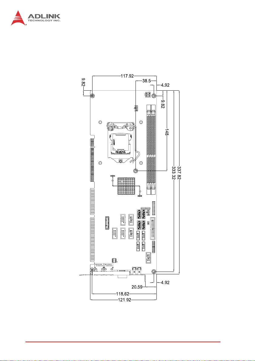
1.6 Mechanical Drawing
Figure 1-2: NuPRO-A40H Board Dimensions
8Introduction
Page 23

1.7 I/O Connectivity
NuPRO-A40H
I/O Bracket Onboard
VGA Y — — DB-15
DVI-D — Y —
LAN1/2 (RJ-45)
PS/2 KB/MS
USB Rear Panel 2 — — —
USB headers — 6 —
COM1-2 — Y —
COM3-6 — Y —
Parallel port
SATA — 4 — —
PCI 32bit/33MHz — — Y Via ITE IT8892E
ISA — — Y Via ITE IT8888G
Table 1-1: NuPRO-A40H I/O Connectivity
Y——
—Y—
—Y—
Golden
Finger
Remarks
cable w/ bracket
optional
(P/N 30-01052-2000)
Act/Link/
Speed LEDs
cable w/ bracket
optional
(P/N 30-01019-2000)
2.54mm pitch
2.54mm pitch
2.00mm pitch
cable w/ bracket
optional
(P/N 30-25019-1000)
Introduction 9
Page 24
1.8 Power Consumption
Intel® Core™ i7-3770 8M Cache 3.40GHz)
T e st Con f ig uration
CPU Intel® Core™ i7-3770 8M Cache 3.40GHz
Memory Transcend 8GB DDR3 1600 DIMMx2
Windows® 7 (Idle)
Power Req. +12V +5V Total
Current (A) 1.47A 2.77A —
Power (W) 17.64W 13.85W 31.49W
Windows® 7, CPU Stress(100% CPU BurnInTest™ Stress)
Power Req. +12V +5V Total
Current (A) 5.33A 2.89A —
Power (W) 63.96W 14.45W 78.41W
Windows 7 Total System Stress (100% BurnInTest™ Stress)
Power Req. +12V +5V Total
Current (A) 6.92A 3.66A —
Power (W) 83.04W 18.3W 101.34W
Inrush Current
Power Req. +12V +5V Total
Current (A) 5.7A 2.69A —
Power (W) 68.4W 13.45W 81.85W
Table 1-2: Core™ i7-3770 Processor Power Consumption
10 Introduction
Page 25
NuPRO-A40H
1.9 Package Contents
Before unpacking, check the shipping carton for any damage. If
the shipping carton and/or contents are damaged, inform your
dealer immediately. Retain the shipping carton and packing
materials for inspection. Obtain authorization from the dealer
before returning any product to ADLINK.
X NuPRO-A40H
X SATA data cable with latch x2
X 2-port USB cable with bracket
X 2-port COM cable with bracket for COM1/COM2
(2.54 mm pitch)
X 2-port COM cable with bracket x2 for COM3-6
(2.0 mm pitch)
X Driver DVD
X User’s manual
Package contents may vary with ordering options.
NOTE:
NOTE:
The NuPRO-A40H must be protected from static discharge and
physical shock. Never remove any of the socketed parts except
WARNING:
at a static-free workstation. Use the anti-static bag shipped with
the product to handle the board. Wear a grounded wrist strap
when installing and/or servicing.
Introduction 11
Page 26

This page intentionally left blank.
12 Introduction
Page 27
NuPRO-A40H
2 Hardware Information
This chapter provides information on the NuPRO-A40H board layout, connector pin assignments, and jumper settings.
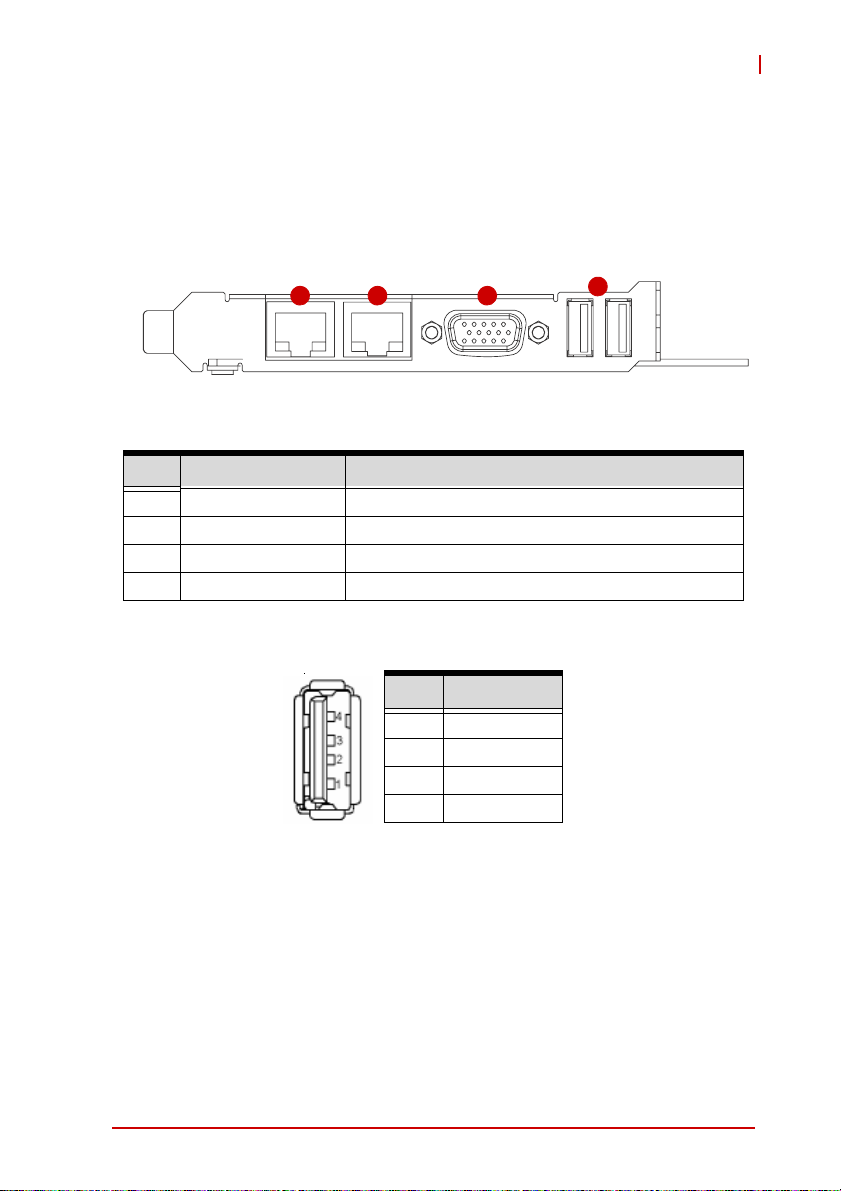
2.1 Rear Panel I/O Ports
1 2 3
Figure 2-1: Rear Panel I/O Ports
Connector Description
1 LAN1 port Gigabit Ethernet (RJ-45)
2 LAN2 port Gigabit Ethernet (RJ-45)
3 VGA port DB-15 connector for CRT or LCD monitor
4 USB 2.0 ports High-speed USB 2.0 ports
4
USB Connector
Pin # Signal Name
1Vcc
2 Data-
3 Data+
4GND
Hardware Information 13
Page 28
LAN (RJ-45) Ports
10BASE-T/
100BASE-TX
1000BASE-T
LED1
LED2
18
Pin #
1 TX+ BI_DA+
2 TX- BI_DA-
3 RX+ BI_DB+
4 -- BI_DC+
5 -- BI_DC-
6 RX- BI_DB-
7 -- BI_DD+
8 -- BI_DD-
Refer to the table below for the LAN port LED definitions.
LED1 LED2
Status Description Status Description
Off No Link Off 10 Mb connection
On Linked Green 100 Mb connection
Blinking Data Activity Orange 1 Gb connection
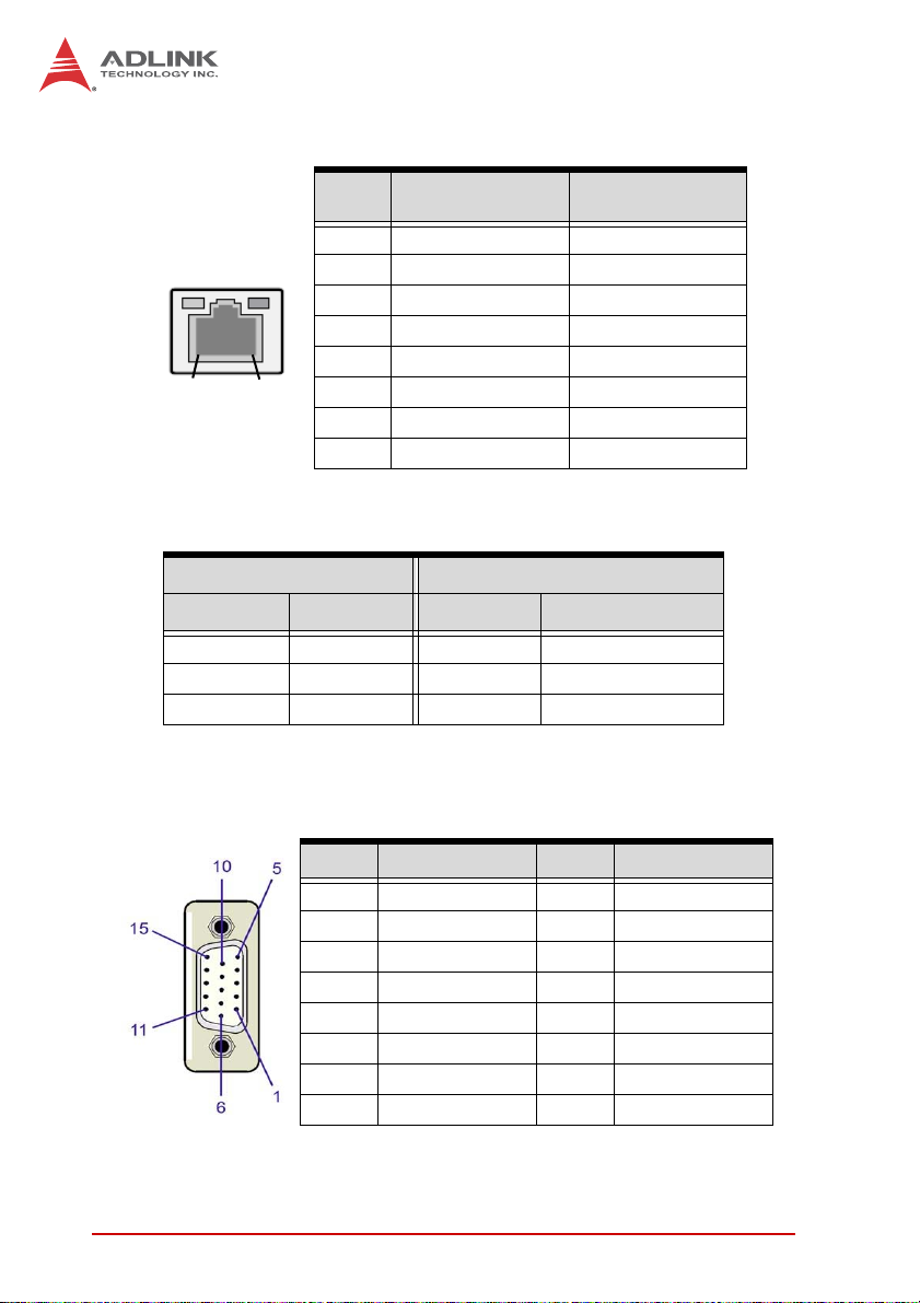
VGA Port
Pin # Signal Pin # Signal
1Red9+5 V
2 Green 10 Ground
3Blue11NC
4 NC 12 DDC DAT
5 Ground 13 HSYNC
6 Ground 14 VSYNC
7 Ground 15 DDC CLK
8 Ground
14 Hardware Information
Page 29
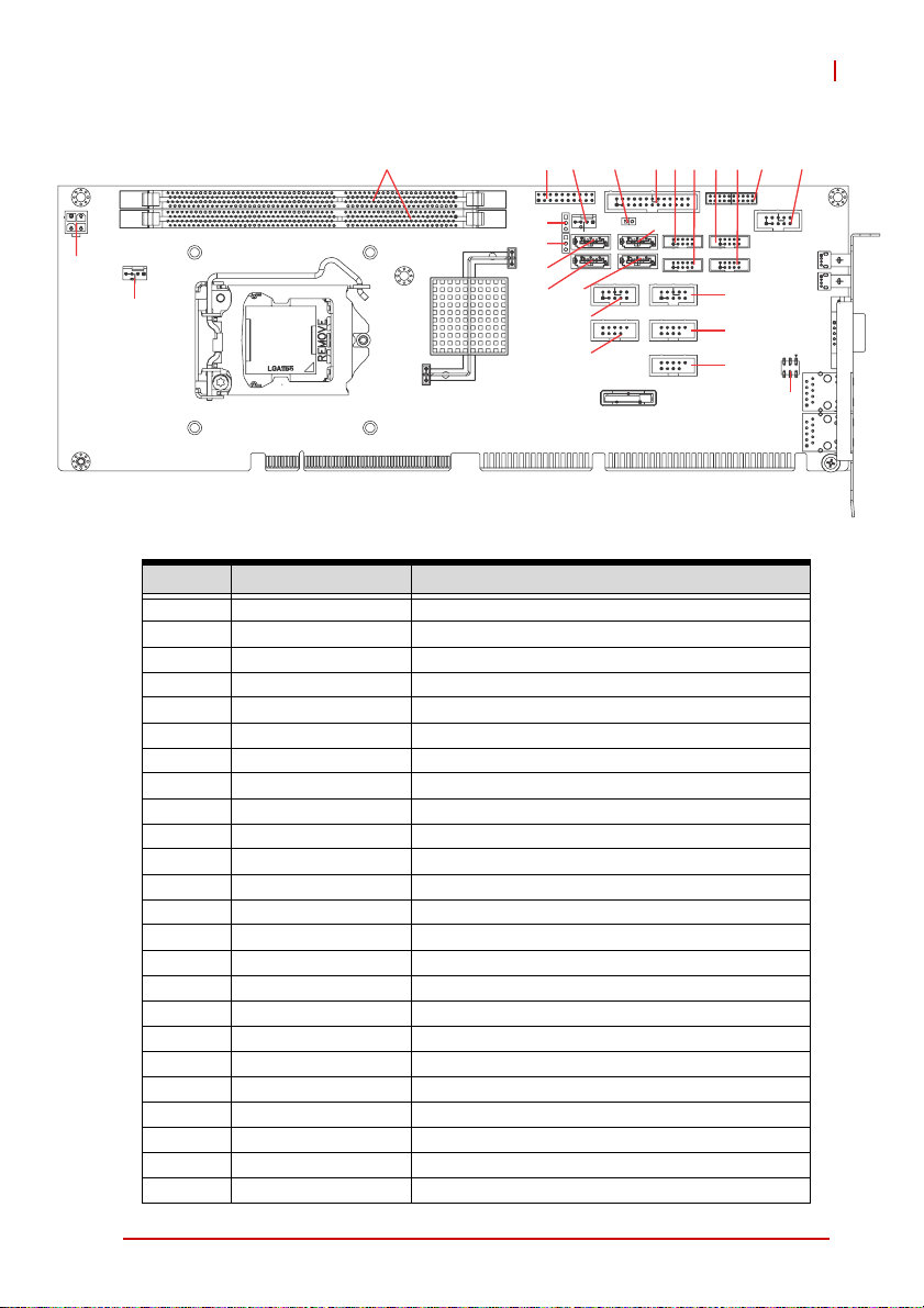
2.2 Board Layout
NuPRO-A40H
426
3 7 8 9 10 11 12
5
24
23
1
25
22
21
20
18
17
19
13
14
15
16
Figure 2-2: Connectors and Jumpers
Connector Description
1 CN24 ATX 12V Power connector
2 DIMM1/2 DDR3 DIMM slots
3 CN23 System Panel pin header
4 FAN2 FAN2 connector
5 CN14 Watchdog disable jumper
6 CN30 Parallel Port connector
7 CN25 COM5 connector
8 CN12 COM3 connector
9 CN19 COM4 connector
10 CN26 COM6 connector
11 CN17 DVI-D onboard connector
12 CN10 COM1 connector
13 CN18 COM2 connector
14/15 CN8/6 USB 8/9, 4/5 headers
16 CN16 PS/2 Keyboard/Mouse pin header
17 CN3 USB 2/3 header
18 CN9 Audio connector
19 CN7 SATA5 connector
20 CN9 SATA4 connector
21 CN2 SATA0 connector
22 CN4 SATA1 connector
23 CN28 Clear CMOS jumper
24 CN29 Clear RTC jumper
25 FAN1 FAN1 connector
Hardware Information 15
Page 30
2.3 Onboard Connectors
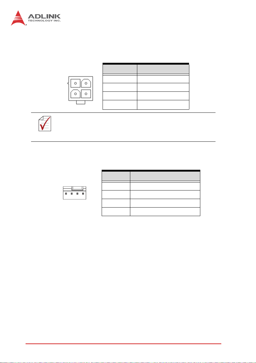
ATX 12V Power Connector (CN24)
Pin # Signal
1GND
2GND
3 +12V DC
4
Pin # Signal
1GND
2 Fan power (+12V)
3 Fan Tachometer
Fan Speed Control
4
NOTE:
NOTE:
2
4
The ATX 12V power connector must be connected to provide
sufficient power to the SBC in either ATX or AT modes. See
“Installing the Power Connectors” on page 36.
1
3
Fan Connectors (FAN1/2)
(1x4 Wafer connector, 2.54mm pitch)
14
+12V DC
16 Hardware Information
Page 31

System Panel Pin Header (CN23)
(2x10 pin header, 2.54mm pitch)
Connects to chassis-mounted buttons, speakers, and LEDs.
Pin # Signal Function Pin Group
1 P5V +5V Power
2NC
3 HC_PLED-L Power LED signal
4NC
5 GND Ground
1
10 20
6 GND Ground
11
7NC
8 ATX_PSON-L ATX Power-On signal
9 P5V_SB_ATX +5V Standby
10 PMEJ Power Control signal
11 HC_SPKR Speaker signal
12 NC
13 NC
14 P5V +5V Power
15 HC_RSTBN-L Reset signal
16 GND Ground
17 HDLED_PWR HDD LED signal
18 P5V +5V Power
19 HC_PBTNJ Power-On signal
20 GND Ground
Reset Button
Power Button
NuPRO-A40H
Power LED
ATX Power
Chassis
Speaker
HDD LED
Hardware Information 17
Page 32

Parallel Port Onboard Connector (CN30)
(2x13 box header, 2.54mm pitch)
Pin # Signal Pin # Signal
1 Line Printer Strobe 2 Auto-Feed
3 Parallel Data 0 4 Error
12
5 Parallel Data 1 6 Initialize
7 Parallel Data 2 8 Select
9 Parallel Data 3 10 Ground
11 Parallel Data 4 12 Ground
13 Parallel Data 5 14 Ground
15 Parallel Data 6 16 Ground
17 Parallel Data 7 18 Ground
19 Acknowledge 20 Ground
21 Busy 22 Ground
23 Paper Empty 24 Ground
25 Select 26 NC
Parallel Port Bracket Connector
(optional cable w/ bracket, P/N: 30-25004-0000)
Pin # Signal Pin # Signal
1 Line Printer Strobe 14 Auto-Feed
2 Parallel Data 0 15 Error
3 Parallel Data 1 16 Initialize
4 Parallel Data 2 17 Select
5 Parallel Data 3 18 Ground
6 Parallel Data 4 19 Ground
7 Parallel Data 5 20 Ground
8 Parallel Data 6 21 Ground
9 Parallel Data 7 22 Ground
10 Acknowledge 23 Ground
11 Busy 24 Ground
12 Paper Empty 25 Ground
13 Select
18 Hardware Information
Page 33

DVI-D Onboard Connector(CN17)
(2x10 Wafer connector, 2.00mm pitch)
Pin # Signal Pin # Signal
1 GND 2 GND
1
2
3 DVI-Clock+ 4 DVI-Data0-
5 DVI-Clock- 6 DVI-Data0+
7 GND 8 GND
9 DVI-I2C-Clock 10 DVI-Data1-
11 DVI-I2C-Data 12 DVI-Data1+
13 GND 14 GND
15 DVI-HPD 16 DVI-Data2-
17 +5V 18 DVI-Data2+
19 GND 20 GND
DVI-D Bracket Connector
(optional cable w/ bracket, P/N 30-01052-2000)
NuPRO-A40H
Pin # Signal Pin # Signal
1 TMDS Data2- 13 TMDS Data3+
2 TMDS Data2+ 14 +5 V Power
3 TMDS Data2/4 Shield 15 GND
4 TMDS Data4- 16 Hot Plug Detect
5 TMDS Data4+ 17 TMDS Data0-
6 DDC Clock [SCL] 18 TMDSData0+
7 DDC Data [SDA] 19 TMDS Data0/5 Shield
8 Analog vertical sync 20 TMDS Data5-
9 TMDS Data1- 21 TMDS Data5+
10 TMDS Data1+ 22 TMDS Clock Shield
11 TMDS Data1/3 Shield 23 TMDS Clock +
12 TMDS Data3- 24 TMDS Clock -
Hardware Information 19
Page 34

COM1 Connector (RS-232/422/485/485+) (CN10)
(2x5 box header, 2.54mm pitch)
Pin # RS-232 RS-422/485+ RS-485
1 DCD TXD- Data-
2 DSR NC NC
3 RXD TXD+ Data+
12
4 RTS NC NC
5 TXD RXD+ NC
910
6 CTS NC NC
7 DTR RXD- NC
8RI NC NC
9 GND GND GND
10 NC NC NC
Note: See BIOS: Advanced > Super I/O to set COM1 to RS-232/
422/485 mode.
COM2/3/4/5/6 Connectors (RS-232) (CN12/18/19/25/26)
(2x5 box header, 2.00mm pitch)
Pin # RS-232 Signal
1DCD
2DSR
3RXD
1
910
4RTS
2
5TXD
6CTS
7DTR
8RI
9GND
10 NC
20 Hardware Information
Page 35

NuPRO-A40H
COM Bracket Connectors
(cables w/ bracket supplied with the NuPRO-A40H - DB9 connector)
Pin # RS-232 RS422/485+ RS485
1 DCD TXD- Data-
2RXD TXD+ Data+
3 TXD RXD+ --
4 DTR RXD --
5 GND GND GND
6 DSR -- --
7 RTS -- --
8 CTS -- --
9 RI -- --
6
1
5
USB 2.0 Connectors (CN3/6/8)
(2x5 box header, 2.54mm pitch)
Pin # Signal Pin # Signal
1+5V 2+5V
3 USB0- 4 USB1-
5 USB0+ 6 USB1+
7GND 8GND
9Key 10NC
Hardware Information 21
Page 36

PS/2 Keyboard/Mouse Pin Header (CN16)
(2x3 pin header, 2.54mm pitch)
1
Pin # Signal Pin # Signal
2
1 KBDATA 2 KBCLK
3 MSDATA 4 MSCLK
5 KM_VCC 6 GND
PS/2 Keyboard/Mouse Bracket Connectors
(optional cable w/ bracket, P/N: 30-01019-2000)
PS/2 Mouse Port (green)
Pin # Signal Function
1MSDATAMouse Data
2 NC not connected
3 GND Ground
4+5V Power
5 CLK Clock
6 NC not connected
PS/2 Keyboard Port (purple)
Pin # Signal Function
1 KBDATA Keyboard Data
2 NC not connected
3 GND Ground
4+5V Power
5 CLK Clock
6 NC not connected
22 Hardware Information
Page 37

NuPRO-A40H
HD Audio Daughter Board Connector (CN9)
(2x5 box header, 2.54mm pitch)
This connector is designed for use with the ADLINK DB-Audio2
daughter board.
Pin # Signal Function
1 GND Ground
2 AUD_BCLK Audio Clock
3 GND Ground
12
910
4 ICH_AUD_SDIN1 Audio Data Input
5 P5V + 5V
6 ICH_AUD_SDOUT Audio Data Output
7 P5V_AUD + 5V
8 P3V3_DVDD 3.3V
9 AUD_SYNC Audio Synchronous
10 AUD_RSTJ Audio Reset
Serial ATA Connectors (CN2/4/7/9)
(7P L-connector, 1.27mm pitch)
Pin # Signal
1GND
1
2TXP
3TXN
4GND
7
5RXN
6RXP
7GND
Hardware Information 23
Page 38

2.4 Jumpers
Watchdog Disable Jumper (CN14)
WDT Status Connection
Normal (default) 1 – 2
Disabled 2 – 3
Clear CMOS Jumper (CN28)
To clear the BIOS settings (RTCRTS# asserts):
1. Power down and disconnect power from the system.
2. Short pins 2-3 on JP1.
3. Reconnect power and power up the system.
4. After power up, remove the jumper cap from pins 2-3
and reinstall it to pins 1-2.
CMOS Status Connection JBAT1
Normal 1 – 2
Clear CMOS 2 – 3
24 Hardware Information
Page 39

NuPRO-A40H
Clear RTC Jumper (CN29).
To clear the BIOS settings and data/time (SRTCRST# and
RTCRST# assert):
1. Power down and disconnect power from the system.
2. Short pins 2-3 on JP1.
3. Reconnect power and power up the system.
After power up, remove the jumper cap from pins 2-3 and reinstall it to pins 1-2.
CMOS Status Connection JBAT1
Normal 1 – 2
Clear CMOS 2 – 3
COM1 Mode Jumper Settings (CN16, CN31)
Short the jumper pins according to the following settings to set
COM1 to RS-232/422/485 mode:
RS-232 RS-422 RS-485
CN16 On On Off
CN31 Off On On
Hardware Information 25
Page 40

This page intentionally left blank.
26 Hardware Information
Page 41

NuPRO-A40H
3 Getting Started
This chapter provides information on how to install components on
the NuPRO-A40H SHB.
3.1 Installing the CPU
The NuPRO-A40H supports an Intel® Core™ i7/i5/i3 or Pentium®
processor in an LGA1155 socket.
Disconnect all power to the board before
installing a CPU to prevent damaging the
WARNING:
To install the CPU:
board and CPU.
Do not touch socket contacts. Damaging the
contacts voids the product warranty. Follow
the installation instructions carefully to avoid
damaging the board components.
1. Press down on the locking arm (A), then push it away from
the socket to disengage it from the retention tab (B).
A
B
Getting Started 27
Page 42

2. Raise the locking arm to unlock the load plate.
3. Lift the load plate to uncover the socket.
4. Remove the plastic protective cover from the socket.
Note the locations of the alignment keys (A) and Pin 1
indicator (B).
B
A
Do NOT touch socket contacts.
WARNING:
28 Getting Started
Page 43

5. Hold the CPU using thumb and forefinger as shown.
Position the CPU over the socket, matching the notches
on the sides of the CPU with the alignment keys on the
socket (A). The golden triangle on the CPU must be
positioned at the corner of the socket with the Pin 1 indicator as shown (B).
AB
The CPU fits into the socket in only one orientation. DO NOT
force it into the socket to avoid causing damage.
WARNING:
NuPRO-A40H
6. Carefully place the CPU into the socket vertically. The
socket has cutouts for your fingers to fit into.
Cutouts
Getting Started 29
Page 44

7. Gently lower the load plate. Make sure the front edge of the
plate is under the screw as indicated.
8. Lower the locking arm and fasten it to the retention tab (A).
The load plate should be locked underneath the screw as
shown (B).
B
A
30 Getting Started
Page 45

NuPRO-A40H
3.2 Installing the CPU Fan and Heatsink
The CPU requires a chassis with an airflow inlet and maximum
internal ambient temperature of 50° C. A especially-designed
CAUTION:
When the CPU fan installation procedures presented here are
inconsistent with the installation procedures you obtained from the
CPU fan and heatsink package, follow the latter.
To install the CPU fan:
CPU fan and heatsink must be installed before using the SHB.
Failure to install a CPU fan and heatsink may damage the system host board and/or the CPU.
1. Apply thermal grease evenly on top of the installed CPU.
2. Lower the CPU fan to the CPU, then secure it using the
provided attachments or screws.
3. Connect the CPU fan cable to the CPU fan connector on
the SHB labeled FAN1 (see “Board Layout” on page 15).
Getting Started 31
Page 46

3.3 Installing Memory Modules
The NuPRO-A40H supports up to 16 GB of DDR3 1333/1600 MHz
memory modules in two DIMM sockets. A DDR3 module has a
240-pin footprint compared to the legacy 184-pin DDR DIMM.
DDR3 modules are notched to facilitate correct installation in the
DIMM sockets.
Disconnect all power to the board before installing a memory
module to prevent damaging the board and memory module .
WARNING:
Memory Configuration Options
The NuPRO-A40H supports 2GB, 4GB and 8GB unbuffered nonECC DDR3 DIMMs in the following configurations:
X Channel A: DIMM1
Channel B: DIMM2
X For dual-channel configuration, the total size of memory
module installed per channel must be the same
(DIMM1 = DIMM2).
X It is recommended that you install DIMMs with the same
CAS latency. For maximum compatibility, install memory
modules with the same brand, model, and/or rating.
To install a memory module:
1. Locate the DIMM sockets on the motherboard.
2. Press the socket’s retaining clips outward to unlock.
32 Getting Started
Page 47

NuPRO-A40H
3. Align the memory module on the socket making sure
that the notch matches the break on the socket.
Notch
Break
4. Insert the module firmly into the slot until the retaining
clips snap back inwards and the module is securely
seated.
Getting Started 33
Page 48

3.4 Installing the Power Connectors
Refer to Section 2.2 Board Layout on page 15 and Section 2.3
Onboard Connectors on page 16 for detailed information on con-
nectors and pin definitions referred to below.
ATX 12V Power Connector
The NuPRO-A40H requires +12V DC power connected to CN24
for proper operation in either ATX or AT modes. If necessary, order
an ATX12V Convert Cable from ADLINK for use with Molex 4-pin
power connectors (P/N 30-00006-0000).
Front Panel Connector
Before powering up the NuPRO-A40H, connect the necessary signals from the backplane to the System Panel pin header (CN23).
The ATX Power Connector pin group (pins 6, 8, 9, 10) and Power
Button pin group (pins 19, 20) must be connected for the system
to power up in ATX mode.
34 Getting Started
Page 49

NuPRO-A40H
4 Driver Installation
This chapter provides information on how to install the
NuPRO-A40H device drivers under Windows XP. The device
drivers are located in the following ADLINK All-in-One DVD
directories:
Chipset \NuPRO\NuPRO-A40H\Chipset\
Display \NuPRO\NuPRO-A40H\VGA\
Ethernet \NuPRO\NuPRO-A40H\Ethernet\
.Net Framework \NuPRO\NuPRO-A40H\Others\
Audio \Audio Daughter Board\DB-Audio2\
Install the Windows operating system before installing any driver.
Most standard I/O device drivers are installed during Windows
installation.
4.1 Chipset Driver
This section describes the installation of the chipset driver.
1. Locate the directory X:\NuPRO\NuPRO-A40H\Chipset\
2. Run the program setup.exe and follow the onscreen
r
on the ADLINK All-in-One DVD, and extract the file
setup.exe from the following archive: Chipset driver_
Intel_INF_Update_Utility_All_WinOS.zip.
instructions. Restart the system if prompted.
4.2 Display Driver
Integrated Intel® HD Graphics
This section describes the driver installation for the Integrated
Intel® HD Graphics.
Follow these instructions to install the display driver:
1. Locate the directory X:\NuPRO\NuPRO-A40H\VGA\ on
the ADLINK All-in-One DVD, and extract the contents of
the following archive:
Microsoft_Net_Framework_v3.5_SP1.zip
Driver Installation 35
Page 50

2. Run the program
Microsoft_Net_Framework_v3.5_SP1.exe and follow the
onscreen instructions.Restart the system if prompted.
3. Locate the directory X:\NuPRO\NuPRO-A40H\VGA\ on
the ADLINK All-in-One DVD, and extract the file
setup.exe from the following archive: VGA_winxp.zip.
4. Run the program setup.exe and follow the onscreen
instructions. Restart the system if prompted.
4.3 Ethernet Driver
Follow these instructions to install the Ethernet driver.
1. Locate the directory
X:\NuPRO\NuPRO-A40H\Ethernet\ on the ADLINK
All-in-One DVD, and extract the file Autorun.exe from the
following archive:
Network_driver_Intel_Network_Adapter_For_Win32.zip.
2. Run the program Autorun.exe and follow the onscreen
instructions. Restart the system if prompted.
4.4 Audio Driver
Follow these instructions to install the audio driver for the optional
DB-Audio2 daughter board.
Before installing the audio driver, check the BIOS settings to
make sure that audio is enabled: Chipset > PCH-IO Config-
NOTE:
NOTE:
uration > PCH Azalia Configuration > Azalia.
1. Place the ADLINK All-in-One DVD to the optical drive.
2. Locate the audio driver from the directory
X:\Audio Daughter Board\DB-Audio2\, then double-click on the setup.exe file to start installation.
3. Follow the screen instructions to complete installation,
then restart the system if prompted.
36 Driver Installation
Page 51

NuPRO-A40H
5 BIOS Setup
The following chapter describes basic navigation for the
AMIBIOS® EFI BIOS setup utility.
5.1 Starting the BIOS
To enter the setup screen, follow these steps:
1. Power on the motherboard
2. Press the < Delete > key on your keyboard when you
see the following text prompt:
< Press DEL to run Setup >
3. After you press the < Delete > key, the main BIOS setup
menu displays. You can access the other setup screens
from the main BIOS setup menu, such as Chipset and
Power menus.
Note: In most cases, the < Delete > key is used to invoke the setup
screen. There are several cases that use other keys, such as
< F1 >, < F2 >, and so on.
BIOS Setup 37
Page 52

Setup Menu
The main BIOS setup menu is the first screen that you can navigate. Each main BIOS setup menu option is described in this
user’s guide.
The Main BIOS setup menu screen has two main frames. The left
frame displays all the options that can be configured. “Grayed”
options cannot be configured, “Blue” options can be.
The right frame displays the key legend. Above the key legend is
an area reserved for a text message. When an option is selected
in the left frame, it is highlighted in white. Often a text message will
accompany it.
Navigation
The BIOS setup/utility uses a key-based navigation system called
hot keys. Most of the BIOS setup utility hot keys can be used at
any time during the setup navigation process.
These keys include < F1 >, < F10 >, < Enter >, < ESC >, < Arrow >
keys, and so on. .
38 BIOS Setup
Page 53

NuPRO-A40H
Note: There is a hot key legend located in the right frame on most
setup screens.
The < F8 > key on your keyboard is the Fail-Safe key. It is not displayed on the key legend by default. To set the Fail-Safe settings
of the BIOS, press the < F8 > key on your keyboard. It is located
on the upper row of a standard 101 keyboard. The Fail-Safe settings allow the motherboard to boot up with the least amount of
options set. This can lessen the probability of conflicting settings.
Hotkey Descriptions
F1 The < F1 > key allows you to display the General Help
screen.
Press the < F1 > key to open the General Help screen.
BIOS Setup 39
Page 54

F10 The < F10 > key allows you to save any changes you have
made and exit Setup. Press the < F10 > key to save your
changes. The following screen will appear:
Press the < Enter > key to save the configuration and exit.
You can also use the < Arrow > key to select Cancel and
then press the < Enter > key to abort this function and return
to the previous screen.
ESC The < Esc > key allows you to discard any changes you have
made and exit the Setup. Press the < Esc > key to exit the
setup without saving your changes. The following screen will
appear:
Press the < Enter > key to discard changes and exit. You can
also use the < Arrow > key to select Cancel and then press
the < Enter > key to abort this function and return to the previous screen.
Enter The < Enter > key allows you to display or change the setup
option listed for a particular setup item. The < Enter > key
can also allow you to display the setup sub-screens.
40 BIOS Setup
Page 55

NuPRO-A40H
5.2 Main Setup
When you first enter the Setup Utility, you will enter the Main setup
screen. You can always return to the Main setup screen by selecting the Main tab. There are two Main Setup options. They are
described in this section. The Main BIOS Setup screen is shown
below.
System & Board Info
BIOS Vendor
Displays the BIOS vendor.
Core Version
Displays the BIOS core version.
BIOS Version
Display the current BIOS revision.
Build Data and Time
Displays the BIOS build data.
Total Memory
Display the current system total memory.
BIOS Setup 41
Page 56

System Time/System Date
Use this option to change the system time and date. Highlight System Time or System Date using the < Arrow > keys. Enter new values using the keyboard. Press the < Tab > key or the < Arrow >
keys to move between fields. The date must be entered in MM/
DD/YY format. The time is entered in HH:MM:SS format.
Note: The time is in 24-hour format. For example, 5:30 A.M. ap-
pears as 05:30:00, and 5:30 P.M. as 17:30:00.
Access Level
Displays the current system access level.
42 BIOS Setup
Page 57

NuPRO-A40H
5.3 Advanced BIOS Setup
Select the Advanced tab from the setup screen to enter the
Advanced BIOS Setup screen. You can select any of the items in
the left frame of the screen, such as SuperIO Configuration, to go
to the sub menu for that item. You can display an Advanced BIOS
Setup option by highlighting it using the < Arrow > keys. The
Advanced BIOS Setup screen is shown below.
The sub menus are described on the following pages.
BIOS Setup 43
Page 58

5.3.1 ACPI Settings
Enable APIC Auto Configuration
BIOS ACPI Auto Configuration. Options: Enabled/Disabled.
ACPI Sleep State
Select the highest ACPI sleep state the system will enter, when
the SUSPEND button is pressed. Options: S1, S3, Suspend
Disable.
AC Power Shutdown
ATX mode: OS will turn off system power when shutdown.
AT mode: OS show It is now safe to turn off your computer.
AT mode will not support S3 & S4.
NOTE:
NOTE:
44 BIOS Setup
Page 59

5.3.2 CPU Configuration
NuPRO-A40H
Active Processor Cores
Number of cores to enable in processor. Options: All, 1, 2.
Limit CPUID Value Maximum
When Enabled, the processor will limit the maximum CPUID
input value to 03h when queried, even if the processor supports a higher CPUID input value. When Disabled, the processor will return the actual maximum CPUID input value of the
processor when queried. Enable this option to allow compatibility with older operating systems.
Execute Disable Bit
Allows you to enable or disable the No-Execution Page Protection Technology. Setting this item to [Disabled] forces the XD
feature flag to always return a zero (0). Options: Enabled, Disabled.
BIOS Setup 45
Page 60

Intel® Virtualization Tech
When enabled, Intel® Virtualization Technology (Intel® VT)
makes a single system appear as multiple independent systems to software. This allows for multiple, independent operating systems to be running simultaneously on a single system.
46 BIOS Setup
Page 61

5.3.3 SATA Configuration
NuPRO-A40H
SATA Mode
Options: IDE, RAID, AHCI.
IDE Legacy/Native Mode Selection
IDE Legacy/Native Mode Selection.
SATA Port 0,1,4,5
Display SATA device name string.
BIOS Setup 47
Page 62

5.3.4 USB Configuration
Legacy USB Support
Legacy USB Support refers to USB mouse and keyboard support. Normally if this option is not enabled, any attached USB
mouse or USB keyboard will not become available until a USB
compatible operating system is fully booted with all USB drivers loaded. When this option is enabled, any attached USB
mouse or USB keyboard can control the system even when
there are no USB drivers loaded on the system. Set this value
to enable or disable the Legacy USB Support.
X Disabled: Set this value to prevent the use of any USB
device in DOS or during system boot.
X Enabled: Set this value to allow the use of USB devices
during boot and while using DOS.
X Auto: This option auto detects USB Keyboards or Mice and
if found, allows them to be utilized during boot and while
using DOS.
48 BIOS Setup
Page 63

NuPRO-A40H
USB transfer time-out
The time-out value for Control, bulk, and Interrupt transfers.
Device reset time-out
USB mass storage device start Unit command time-out.
Device power-up delay
Maximum time the device will take before it properly reports
itself to the Host Controller. 'Auto' uses default value: for a Root
port it is 100ms, for a Hub port the delay is taken from Hub
descriptor.
Mass Storage Devices:
Mass storage device emulation type. 'AUTO' enumerates
devices according to their media format. Optical drives are
emulated as 'CDROM', drives with no media will be emulated
according to a drive type. Options: Auto, Floppy, Forced FDD,
Hard Disk, CD-ROM.
BIOS Setup 49
Page 64

5.3.5 Super IO Configuration
Serial Port 1-6 Configuration
Enter the submenu for each serial port to enable/disable and
view the I/O port and IRQ settings.
Parallel Port Configuration
Enter the submenu to enable/disable the parallel port and
specify the base I/O port address.
50 BIOS Setup
Page 65

5.3.6 Serial Port Console Redirection
NuPRO-A40H
COM1~6 Console Redirection
Options: Enabled/Disabled.
BIOS Setup 51
Page 66

Console Redirection Settings
The settings specify how the host computer and the remote
computer exchange data. Both computers should have the
same or compatible settings.
Terminal Type
This option is used to select either VT100/VT-UTF8 or ANSI
terminal type. Options: VT100, VT100+, VT-UTF8, ANSI.
Bits per second
Select the bits per second you want the serial port to use for
console redirection. The options are 115200, 57600, 38400,
19200, 9600.
Data Bits
Select the data bits you want the serial port to use for console
redirection. Set this value to 7 and 8.
Parity
Set this option to select Parity for console redirection. The settings for this value are None, Even, Odd, Mark and Space.
Stop B its
Stop bits indicate the end of a serial data packet. (A start bit
indicates the beginning). The standard setting is 1 stop bit.
Communication with slow devices may require more than 1
stop bit. Set this value to 1 and 2.
52 BIOS Setup
Page 67

NuPRO-A40H
Flow Control
Set this option to select Flow Control for console redirection.
The settings for this value are None, Hardware RTS/CTS.
Record Mode
With this mode enabled only text will be sent., allowing capture
of Terminal data. Set this value to Enabled or Disabled.
Resolution 100x31
Enable or disable extended terminal resolution. Set this value
to Enabled or Disabled.
Legacy OS Redirection Resolution
On a legacy OS, the number of Rows and Columns supported
by redirection. Set this value to 80x24 and 80x25.
Serial Port for Out-of-Band Management
These settings control the ACPI serial port redirection table
(SPCR) which is used by Windows servers to provide Windows
Emergency Management Services (EMS) and is independent
from console redirection output. OoB Management or EMS
allows the remote management of selected components of
Windows servers, even when a server is not connected to the
network or the network is not available
Out-of-Band Mgmt Port
Selects the serial port used for Out-of-Band Management.
BIOS Setup 53
Page 68

Terminal Type
VT-UTF8 is the preferred terminal type for out-of-band management. The next best choice is VT100+ and then VT100.
See above, in Console Redirection Settings page, for more
Help with Terminal Type/Emulation. Options: VT100, VT100+,
VT-UTF8, ASNI.
Bits per second
Select the bits per second you want the serial port to use for
console redirection. The options are 115200, 57600, 38400,
19200, 9600.
Flow Control
Set this option to select Flow Control for console redirection.
The settings for this value are None, Hardware RTS/CTS.
Data Bits
Displays the frame width for Out-of-Band Management.
Parity
Displays the parity for Out-of-Band Management.
Stop B its
Displays the number of stop bits for Out-of-Band Management.
54 BIOS Setup
Page 69

NuPRO-A40H
5.3.7 CPU PPM Configuration
EIST
The CPU speed is controlled by the operating system. Set this
value to Enabled/Disabled.
Turbo Mode
Enabled/Disabled CPU Turbo Mode in OS.
CPU C3 Report
CPU C3 (ACPI C2) report to OS. Set this value is Enabled/Disabled.
CPU C6 Report
CPU C6(ACPI C3) report to OS. Set this value is Enabled/Disabled.
CPU C7 Report
CPU C7(ACPI C3) report to OS. Set this value is Enabled/Disabled.
BIOS Setup 55
Page 70

5.4 Chipset Setup
Select the Chipset tab from the setup screen to enter the Chipset
BIOS Setup screen. You can select any of the items in the left
frame of the screen to go to the sub menu for that item. The Chipset BIOS Setup screen is shown below.
56 BIOS Setup
Page 71

5.4.1 PCH-IO Configuration
NuPRO-A40H
High Precision Timer
Enabled/Disabled the High Precision Event Timer
Slp_S4 Assertion Width.
Select a minimum assertion width of the SLP_S4# signal.
BIOS Setup 57
Page 72

Restore on AC Power Loss
Determines which state the computer enters when AC power is
restored after a power loss. The options for this value are Last
State, Power On and Power Off.
X Power Off: Set this value to always power off the system
while AC power is restored.
X Power On: Set this value to always power on the system
while AC power is restored.
X Last State: Set this value to power off/on the system depend-
ing on the last system power state while AC power is restored.
USB Configuration
EHCI 1
Enabled/Disabled USB 2.0 (EHCI) Support. Options: Enable, Disable.
EHCI 2
Enabled/Disabled USB 2.0 (EHCI) Support. Options: Enable, Disable.
58 BIOS Setup
Page 73

NuPRO-A40H
PCH Azalia Configuration
Azalia
Control Detection of the Azalia device. Disabled=Azaila will be
unconditionally disabled.
X Enabled = Azaila will be unconditionally Enabled
X Auto=Azalia will be enabled if present, disabled otherwise.
Azalia Docking Support
Enabled/Disabled Azalia Docking Support of Audio Controller.
Azalia PME
Enabled/Disabled Power Management Capability of Audio Controller.
BIOS Setup 59
Page 74

5.4.2 System Agent (SA) Configuration
Graphics Configuration
Graphic Turbo IMON Current
Graphic Turbo IMON Current values supported: 14-31 μA.
60 BIOS Setup
Page 75

NuPRO-A40H
Primary Display
Allows you to select which graphics controller to use as the primary boot device. Options: Auto, IGFX, PEG, PCI.
Internal Graphics
Keep IGD enabled based on the setup options. Options:Auto,
Disabled, Enabled
GTT Size
Set GTT (Graphics Memory Manager) size. Options:1MB, 2MB
Aperture Size
Options: 128MB, 256MB, 512MB
DVMT Pre-Allocated
Select DVMT 5.0 Pre-allocated(Fixed) Graphics Memory size
used by the Internal Graphics Device.
DVMT Total Gfx Mem
Select DVMT/Fixed memory size used by the Integrated
Graphics Device. Options: 128MB, 256MB, Maximum.
Gfx Low Power Mode
Options: Enabled, Disabled
Graphics Performance Analyzers
Enabled or Disable Intel Graphics Performance Analyzers
Counters.
BIOS Setup 61
Page 76

Memory Configuration
Memory Remap
Enabled or Disable Memory remap above 4G.
62 BIOS Setup
Page 77

NuPRO-A40H
5.5 Boot Configuration
Select the Boot tab from the setup screen to enter the Boot BIOS
Setup screen. You can select any of the items in the left frame of
the screen, such as Boot Device Priority, to go to the sub menu for
that item. You can display a Boot BIOS setup option by highlighting it using the < Arrow > keys. The Boot Configuration screen is
shown below:
Setup Prompt Timeout
Number of seconds to wait for setup activation. 65535
(0xFFFF) means wait indefinitely.
Bootup NumLock State
This setting determines the state of the NumLock function on
bootup. Options: On, Off.
BIOS Setup 63
Page 78

Quiet Boot
When this feature is enabled, the BIOS will display the fullscreen logo during the boot-up sequence, hiding normal POST
messages. When it is disabled, the BIOS will display the normal POST messages, instead of the full-screen logo.
Fast Boot
Enabled/Disabled boot with initialization of a minimal set of
devices required to launch active boot option. Has no effect for
BBS boot options.
Gate A20 Active
Options: Upon Request, Always.
Option ROM Messages
Set display mode for Option ROM.
INT19 Trap Response
BIOS reaction on INT19 trapping by Option ROM: IMMEDIATE- execute the trap right away; POSTPONED-execute the
during legacy boot.
Boot Option Priorities
Set the boot device options to determine the sequence in which
the computer checks which device to boot from.
Hard Drive BBS Priorities
The Boot devices are listed in groups by device type. First
press <Enter> to enter the sub-menu. You may then use the
arrow keys to select the desired device, then press <+>, <-> or
<PageUp>, <PageDown> key to move it up/down in the priority
list. For example, USB storage disks will be listed as "USB
Drives" in the sub-menu. Only the first device in each device
group will be available for selection in the Boot Device Priority
option.
64 BIOS Setup
Page 79

NuPRO-A40H
CSM Parameters
Launch CSM
This Option controls if CSM will be launched.
Boot Option Filter
This Option controls what device system can boot to.
Launch PXE OpRom Policy
Controls the execution of UEFI and Legacy PXE OpRom.
Launch Storage OpRom Policy
Controls the execution of UEFI and Legacy Storage OpRom.
Launch Video OpRom Policy
Controls the execution of UEFI and Legacy Video OpRom.
Other PCI device ROM priority
For PCI device other than network, mass storage or Video
defines which OpRom to launch.
BIOS Setup 65
Page 80

5.6 Security Setup
Password Support
Two Levels of Password Protection
Provides both a Supervisor and a User password. If you use
both passwords, the Supervisor password must be set first.
The system can be configured so that all users must enter a
password every time the system boots or when Setup is executed, using either or either the Supervisor password or User
password.
The Supervisor and User passwords activate two different levels of password security. If you select password support, you
are prompted for a one to six character password. Type the
password on the keyboard. The password does not appear on
the screen when typed. Make sure you write it down. If you forget it, you must drain NVRAM and re-configure.
66 BIOS Setup
Page 81

NuPRO-A40H
Remember the Password
Keep a record of the new password when the password is
changed. If you forget the password, you must erase the system configuration information in NVRAM.
To access the sub menu for the following items, select the item
and press < Enter >:
X Change Administrator Password
X Change User Password
X Clear User Password
Administrator Password
Indicates whether a Administrator password has been set.
User Password
Indicates whether a user password has been set.
BIOS Setup 67
Page 82

5.7 System Management
Power Up Watchdog
The Power Up Watchdog resets the system after a certain amount
of time after power up.
68 BIOS Setup
Page 83

NuPRO-A40H
5.8 Exit Menu
Select the Exit tab from the setup screen to enter the Exit BIOS
Setup screen. You can display an Exit BIOS Setup option by highlighting it using the < Arrow > keys. The Exit BIOS Setup screen is
shown below.
Save Changes and Exit
When you have completed the system configuration changes,
select this option to leave Setup and reboot the computer so the
new system configuration parameters can take effect.
Save Configuration Changes and Exit Now?
[Ok] [Cancel]
appears in the window. Select Ok to save changes and exit.
BIOS Setup 69
Page 84

Discard Changes and Exit
Select this option to quit Setup without making any permanent
changes to the system configuration.
Discard Changes and Exit Setup Now?
[Ok] [Cancel]
appears in the window. Select Ok to discard changes and exit.
Save Changes and Reset
Reset the system after saving the changes.
Discard Changes and Reset
Reset system setup without saving any changes.
Save Changes
Save changes made so far to any of the setup options.
Discard Changes
Select Discard Changes from the Exit menu and press < Enter >.
Select OK to discard changes.
Restore Defaults
Restore/Load Default values for all the setup options.
Save as User Defaults
Save the changes made so far as User Defaults.
Restore User Defaults
Restore the User Defaults to all the setup options.
Boot Override
This group of functions includes a list of devices within the boot
order. Select a drive to immediately boot that device regardless of
the current boot order. If you are booting to the EFI Shell, an exit
from the shell returns to Setup.
70 BIOS Setup
Page 85

NuPRO-A40H
Appendix A - Watchdog Timer
To use the Watchdog Timer on the NuPRO-A40H, first download
the WDT driver from the product page on the ADLINK website:
www.adlinktech.com/PD/web/PD_detail.php?cKind=&pid=1256
Install the driver by extracting the appropriate version for your
Windows operating system (32 or 64-bit), and copying it to the fol-
lowing location: C:\Windows\System32\drivers.
A sample program for configuring the NuPRO-A40H’s watchdog
timer is shown below.
A.1 Sample Code
#include <stdlib.h>
#include <float.h>
#include "Sema.h"
#include "SemaLog.h"
#include "ErrorCodes.h"
#include "Debug.h"
#include "Conv.h"
#include "dmi_info.h"
#include "Version.h"
#ifdef WIN32
#include <windows.h>
#else
#include <string.h>
#include <unistd.h>
#include <ctype.h>
#endif
.
typedef struct
{
bool SetWatchdog;// Set/Reset/Disable watchdog?
word Watchdog;// Num of seconds for wdt to trigger
}tCmdLineArgs;
tCmdLineArgs CmdLineArgs;
char* ExeName;
Watchdog Timer 71
Page 86

void ErrorMessage(char *Message)
{
Sema_EventLogError(Message);
exit(-1);
}
void ParseArgs(int argc, char* argv[], tCmdLineArgs
*Args)
{
int i;
for (i=1; i<argc; i++)
{
if (strncmp(argv[i], "wdt", 3)==0)
{
if (++i >= argc)
{
ErrorMessage("Watchdog: Timeout missing");
}
Args->Watchdog = atoi(argv[i]);
Args->SetWatchdog = true;
}
}
}
void PrintData(tCmdLineArgs Args)
{
if (Args.SetWatchdog)
{
Sema_SetWatchdog(Args.Watchdog);
printf("Watchdog set to %d seconds.\n",
Args.Watchdog);
}
}
int main(int argc, char* argv[])
{
memset(&CmdLineArgs, 0, sizeof(tCmdLineArgs));
ParseArgs(argc, argv, &CmdLineArgs);
Sema_Init();
72 Watchdog Timer
Page 87

PrintData(CmdLineArgs);// Print requested data to
console
Sema_Close();
return 0;
}
NuPRO-A40H
Watchdog Timer 73
Page 88

This page intentionally left blank.
74 Watchdog Timer
Page 89

Appendix B - System Resources
B.1 System Memory Map
NuPRO-A40H
Address Range
(decimal)
(4GB-2MB)
(4GB-18MB) –
(4GB-17MB-1)
(4GB-20MB) –
(4GB-19MB-1)
15MB – 16MB
960 K – 1024 K F0000 – FFFFF 64 KB System BIOS Area
896 K – 960 K E0000 – EFFFF 64 KB Extended System BIOS Area
768 K – 896 K C0000 – DFFFF 128 KB
640 K – 768 K A0000 – BFFFF 128 KB Video Buffer & SMM space
Address Range
(hex)
FFE00000 –
FFFFFFFF
FEE00000 –
FEEFFFFF
FEC00000 –
FECFFFFF
F00000 –
FFFFFF
Table B-1: System Memory Map
Size Description
2 MB High BIOS Area
1 MB FSB Interrupt Memory Space
1 MB APIC Configuration Space
1 MB ISA Hole
PCI expansion ROM area
C0000-CE7FF: Onboard VGA BIOS
CE800-D07FF: Intel i211 PXE option ROM
when onboard LAN boot ROM is enabled.
B.2 Direct Memory Access Channels
Channel Number Data Width System Resource
08-bits
18-bits
28-bits
38-bits
4 Reserved - cascade channel
5 16-bits Open
6 16-bits Open
7 16-bits Open
Parallel port
Parallel port
Diskette drive
Parallel port
(1)
(1)
(1)
(1)
Table B-2: Direct Memory Access Channels
Note (1): DMA channel 0/1/3 is selected when using the parallel port.
System Resources 75
Page 90

B.3 IO Map
Hex Range Device
000-01F DMA controller 1, 8237A-5 equivalent
020-02D and 030-03F Interrupt controller 1, 8259 equivalent
02E-02F LPC SIO (ITE8783) configuration index/data registers
040-05F Timer, 8254-2 equivalent
060, 062, 064, 066,
068-06F
061, 063, 065, 067 NMI control and status
070-07F Real Time Clock Controller( bit 7 -NMI mask)
080-091 DMA page register
092 Reset (Bit 0)/ Fast Gate A20 (Bit 1)
93-9F DMA page registers continued
0A0-0B1 and 0B4-0BF Interrupt controller 2, 8259 equivalent
0B2 and 0B3 APM control and status port respectively
0C0-0DF DMA controller 2, 8237A-5 equivalent
0F0 Co-processor error register
2E0-2EF Serial Port 6
2E8-2EF Serial Port 4
2F0-2F7 Serial Port 5
2F8-2FF Serial Port 2
378-37F Parallel port
3B0-3BB and 3BF Mono/VGA mode video
3BC-3BE Reserved for parallel port
3C0-3DF VGA registers
3E8-3FF Serial port 3
3F8-3FF Serial port 1
4D0 Master PIC Edge/Level Trigger register
4D1 Slave PIC Edge/Level Trigger register
CF8 PCI configuration address register (32 bit I/O only)
CF9 Reset Control register (8 bit I/O)
CFC-CFF PCI configuration data register
500-57F GPIO Base Address for SB
400-45F PM (ACPI) Base Address for SB
8742 equivalent (keyboard)
76 System Resources
Page 91

Hex Range Device
460-47F Alias for ICH TCO base address.
0A00~0AFF
F040-F05F SMBus base address for SB
Reserved for SIO functions base address (ex:
HardWare Monitor /GPIO etc)
Table B-3: IO Map
B.4 I nterrupt Request (IRQ) Lines
IRQ Lines PIC Mode
NuPRO-A40H
IRQ#
0 Counter 0 N/A No
1 Keyboard controller N/A No
2
3 Serial Port 2 (COM2)
4
5
6
7 Parallel port / PCI / ISA
8 Real-time clock N/A No
9 SCI / PCI
10
11 PCI / ISA
12 PS/2 Mouse / PCI / ISA
Typical Interrupt
Resource
Cascade interrupt from
slave PIC
Serial Port 1 (COM1) /
PCI / ISA
Serial Port 3,4 (COM3
,COM4) PCI / ISA
Serial Port 5 (COM5)
PCI / ISA
Serial Port 6 (COM6)
PCI / ISA
Connected to Pin Available
N/A No
IRQ3 via SERIRQ, IRQ3
at ISA bus
IRQ4 via SERIRQ, IRQ4
at ISA bus
IRQ5 via SERIRQ, IRQ5
at ISA bus
IRQ6 via SERIRQ No
IRQ7 via SERIRQ, IRQ7
at ISA bus
IRQ9 via SERIRQ, IRQ9
at ISA bus
IRQ10 via SERIRQ,
IRQ10 at ISA bus
IRQ11 via SERIRQ,
IRQ11 at ISA bus
IRQ12 via SERIRQ,
IRQ12 at ISA bus
Note (1), (2)
Note (1)
Note (1)
Note (1)
Note (1)
Note (1)
Note (1)
Note (1)
System Resources 77
Page 92

IRQ#
13 Math Processor N/A No
14
15
Typical Interrupt
Resource
Primary IDE controller /
PCI / ISA
Secondary IDE
controller / PCI / ISA
T able B-4: IRQ Lines PIC Mode
Notes:
(1) These IRQs can be used for PCI devices when the onboard device
is disabled. If the IRQ is from ISA, the user must reserve the IRQ for
ISA in the BIOS setup menu.
(2) The BIOS does not open the IRQ 9 setting for the ISA bus.
Connected to Pin Available
IRQ14 via SERIRQ,
IRQ14 at ISA bus
IRQ15 via SERIRQ,
IRQ15 at ISA bus
Note (1)
Note (1)
IRQ Lines APIC Mode
IRQ#
0 Counter 0 N/A No
1 Keyboard controller N/A No
2
3
4
5
6
7 Parallel port / ISA
8 Real-time clock N/A No
9 SCI / PCI
T ypical Interrupt
Resource
Cascade interrupt from
slave PIC
Serial Port 2 (COM2) /
ISA
Serial Port 1 (COM1) /
ISA
Serial Port 3,4 (COM3
,COM4) /ISA
Serial Port 5 (COM5)/
ISA
Connected to Pin Available
N/A No
IRQ3 via SERIRQ, IRQ3 at
ISA bus
IRQ4 via SERIRQ, IRQ4 at
ISA bus
IRQ5 via SERIRQ, IRQ5 at
ISA bus
IRQ6 via SERIRQ No
IRQ7 via SERIRQ, IRQ7 at
ISA bus
IRQ9 via SERIRQ, IRQ9 at
ISA bus
Note (1), (2)
Note (1)
Note (1)
Note (1)
Note (1)
78 System Resources
Page 93

NuPRO-A40H
IRQ#
10
11 ISA
12 PS/2 Mouse / ISA
13 Math Processor N/A No
14
15
16 N/A
17 N/A PCI SLOT4 Yes
18 N/A
19 N/A
20 N/A N/A No
21 N/A N/A No
22 N/A N/A No
23 N/A EHCI Controller #1 No
Typical Interrupt
Resource
Serial Port 6 (COM6) /
ISA
Primary IDE controller /
ISA
Secondary IDE
controller / ISA
Ta b le B-5: IRQ Lines AP IC Mode
Connected to Pin Available
IRQ10 via SERIRQ, IRQ10 at
ISA bus
IRQ11 via SERIRQ, IRQ11 at
ISA bus
IRQ12 via SERIRQ, IRQ12 at
ISA bus
IRQ14 via SERIRQ, IRQ14 at
ISA bus
IRQ15 via SERIRQ, IRQ15 at
ISA bus
PCIE Port 0, EHCI Controller
#2, I.G.D,
Intel Management Engine
Interface,PCIE to PCI
Bridge(IT8892),PCI SLOT1
PCIE Port 2, Intel I211 LAN.
PCI SLOT3
PCIE Port 3 SATA Host
controller #1, SATA Host
controller #2, Intel I211 LAN.
PCI SLOT2
Note (1)
Note (1)
Note (1)
Note (1)
Note (1)
Yes
Yes
Yes
Notes:
(1) These IRQs can be used for PCI devices when the onboard device
is disabled. If the IRQ is from ISA, the user must reserve the IRQ for
ISA in the BIOS setup menu.
(2) The BIOS does not open the IRQ 9 setting for the ISA bus.
System Resources 79
Page 94

PCI Configuration Space Map
Bus # Device # Function # Routing Description
00h 00h 00h N/A Intel Host-Hub Bridge
00h 02h 00h Internal
00h 16h 00h Internal
00h 1Ah 07h Internal Intel USB EHCI Controller #2
00h 1Bh 00h Internal High Definition Audio controller
00h 1Ch 00h Internal Intel ICH Express Root port 0
00h 1Ch 02h Internal Intel ICH Express Root port 2
00h 1Ch 03h Internal Intel ICH Express Root port 3
00h 1Dh 00h Internal Intel USB EHCI Controller #1
00h 1Fh 00h N/A Intel LPC Interface Bridge
00h 1Fh 02h Internal Intel SATA Host controller #1
00h 1Fh 03h Internal Intel SMBus Controller
00h 1Fh 05h Internal Intel Host SATA controller #2
01h 00h 00h Internal IT8892 PCIE to PCI Bridge
02h 07h 00h Internal IT8888 PCI to ISA Brdige
02h 0Ch 00h Internal PCI Slot 4
02h 0Dh 00h Internal PCI Slot 3
02h 0Eh 00h Internal PCI Slot 2
02h 0Fh 00h Internal PCI Slot 1
03h 0Fh 00h Internal Intel I211 Lan
04h 0Fh 00h Internal Intel I211 Lan
Intel Integrated Graphics
Device
Intel Management Engine
Interface
Table B-6: PCI Configuration Space Map
80 System Resources
Page 95

PCI Interrupt Routing Map
PIRQ A B C D E F G H
INT Line INTA INTB INTC INTD
VGA X
SATA Controller X
SATA Controller 1 X
EHCI 1 X
EHCI 2 X
HAD X
PCIE port0 INTA INTB INTC INTD
PCIE port2 INTC INTD INTA INTB
PCIE port3 INTD INTA INTB INTC
IT 8892 X
PCI Slot 1 X
PCI Slot 2 X
PCI Slot 3 X
PCI Slot 4 X
Intel I211 #1 X
Intel I211 #2 X
Table B-7: PCI Interrupt Routing Map
NuPRO-A40H
System Resources 81
Page 96

This page intentionally left blank.
82 System Resources
Page 97

NuPRO-A40H
Important Safety Instructions
For user safety, please read and follow all instructions,
WARNINGS, CAUTIONS, and NOTES marked in this manual
and on the associated equipment before handling/operating the
equipment.
X Read these safety instructions carefully.
X Keep this user’s manual for future reference.
X Read the specifications section of this manual for detailed
information on the operating environment of this equipment.
X When installing/mounting or uninstalling/removing
equipment:
Z Turn off power and unplug any power cords/cables.
X To avoid electrical shock and/or damage to equipment:
Z Keep equipment away from water or liquid sources;
Z Keep equipment away from high heat or high humidity;
Z Keep equipment properly ventilated (do not block or
cover ventilation openings);
Z Make sure to use recommended voltage and power
source settings;
Z Always install and operate equipment near an easily
accessible electrical socket-outlet;
Z Secure the power cord (do not place any object on/over
the power cord);
Z Only install/attach and operate equipment on stable
surfaces and/or recommended mountings; and,
Z If the equipment will not be used for long periods of time,
turn off and unplug the equipment from its power source.
Important Safety Instructions 83
Page 98

X Never attempt to fix the equipment. Equipment should only
be serviced by qualified personnel.
A Lithium-type battery may be provided for uninterrupted, backup
or emergency power.
Risk of explosion if battery is replaced with one of an incorrect
WARNING:
type. Dispose of used batteries appropriately.
X Equipment must be serviced by authorized technicians
when:
Z The power cord or plug is damaged;
Z Liquid has penetrated the equipment;
Z It has been exposed to high humidity/moisture;
Z It is not functioning or does not function according to the
user’s manual;
Z It has been dropped and/or damaged; and/or,
Z It has an obvious sign of breakage.
84 Important Safety Instructions
Page 99

Getting Service
Contact us should you require any service or assistance.
ADLINK Technology, Inc.
Address: 9F, No.166 Jian Yi Road, Zhonghe District
New Taipei City 235, Taiwan
ᄅקؑխࡉ৬ԫሁ 166 ᇆ 9 ᑔ
Tel: +886-2-8226-5877
Fax: +886-2-8226-5717
Email: service@adlinktech.com
Ampro ADLINK Technology, Inc.
Address: 5215 Hellyer Avenue, #110, San Jose, CA 95138, USA
Tel: +1-408-360-0200
Toll Free: +1-800-966-5200 (USA only)
Fax: +1-408-360-0222
Email: info@adlinktech.com
ADLINK Technology (China) Co., Ltd.
Address: Ϟ⍋Ꮦ⌺ϰᮄᓴ∳催⾥ᡔು㢇䏃 300 ো(201203)
300 Fang Chun Rd., Zhangjiang Hi-Tech Park,
Pudong New Area, Shanghai, 201203 China
Tel: +86-21-5132-8988
Fax: +86-21-5132-3588
Email: market@adlinktech.com
NuPRO-A40H
ADLINK Technology Beijing
Address: ࣫ҀᏖ⍋⎔Ϟഄϰ䏃 1 োⲜ߯ࡼ E ᑻ 801 ᅸ(100085)
Tel: +86-10-5885-8666
Fax: +86-10-5885-8626
Email: market@adlinktech.com
ADLINK Technology Shenzhen
Address: ⏅ഇᏖቅ⾥ᡔು催ᮄϗ䘧᭄ᄫᡔᴃು
Tel: +86-755-2643-4858
Fax: +86-755-2664-6353
Email: market@adlinktech.com
LiPPERT ADLINK Technology GmbH
Address: Hans-Thoma-Strasse 11, D-68163, Mannheim, Germany
Tel: +49-621-43214-0
Fax: +49-621 43214-30
Email: emea@adlinktech.com
Rm. 801, Power Creative E, No. 1, B/D
Shang Di East Rd., Beijing, 100085 China
A1 2 ὐ C (518057)
2F, C Block, Bldg. A1, Cyber-Tech Zone, Gao Xin Ave. Sec. 7,
High-Tech Industrial Park S., Shenzhen, 518054 China
Getting Service 85
Page 100

ADLINK Technology, Inc. (French Liaison Office)
Address: 15 rue Emile Baudot, 91300 Massy CEDEX, France
Tel: +33 (0) 1 60 12 35 66
Fax: +33 (0) 1 60 12 35 66
Email: france@adlinktech.com
ADLINK Technology Japan Corporation
Address: ͱ101-0045 ᵅҀ䛑ҷ⬄⼲⬄䤯ފ⬎ 3-7-4
Tel: +81-3-4455-3722
Fax: +81-3-5209-6013
Email: japan@adlinktech.com
ADLINK Technology, Inc. (Korean Liaison Office)
Address: 昢殾柢 昢爎割 昢爎壟 1675-12 微汾瘶捒娯 8猻
Tel: +82-2-2057-0565
Fax: +82-2-2057-0563
Email: korea@adlinktech.com
ADLINK Technology Singapore Pte. Ltd.
Address: 84 Genting Lane #07-02A, Cityneon Design Centre,
Tel: +65-6844-2261
Fax: +65-6844-2263
Email: singapore@adlinktech.com
ADLINK Technology Singapore Pte. Ltd. (Indian Liaison Office)
Address: 1st Floor, #50-56 (Between 16th/17th Cross) Margosa Plaza,
Tel: +91-80-65605817, +91-80-42246107
Fax: +91-80-23464606
Email: india@adlinktech.com
⼲⬄ 374 ɛɳ 4F
KANDA374 Bldg. 4F, 3-7-4 Kanda Kajicho,
Chiyoda-ku, Tokyo 101-0045, Japan
8F Mointer B/D,1675-12, Seocho-Dong, Seocho-Gu,
Seoul 137-070, Korea
Singapore 349584
Margosa Main Road, Malleswaram, Bangalore-560055, India
ADLINK Technology, Inc. (Israeli Liaison Office)
Address: 6 Hasadna St., Kfar Saba 44424, Israel
Tel: +972-9-7446541
Fax: +972-9-7446542
Email: israel@adlinktech.com
86 Getting Service
 Loading...