

Page 1

M-945
MicroATX Industrial Motherboard
User’s Manual
Manual Rev. 2.00
Revision Date: September 13, 2006
Part No: 50-13053-1000
Advance Technologies; Automate the World.
Page 2

Copyright 2006 ADLINK TECHNOLOGY INC.
All Rights Reserved.
The information in this document is subject to change without prior
notice in order to improve reliability, design, and function and does
not represent a commitment on the part of the manufacturer.
In no event will the manufacturer be liable for direct, indirect, special, incidental, or consequential damages arising out of the use or
inability to use the product or documentation, even if advised of
the possibility of such damages.
This document contains proprietary information protected by copyright. All rights are reserved. No part of this manual may be reproduced by any mechanical, electronic, or other means in any form
without prior written permission of the manufacturer.
Trademarks
Microsoft
dows
®
, Windows® NT, Windows® 98, Windows® 2000, Win-
®
XP are registered trademarks of Microsoft Corporation.
Product names mentioned herein are used for identification purposes only and may be trademarks and/or registered trademarks
of their respective companies.
CAUTION RISK OF EXPLOSION IF BATTERY IS REPLACED BY
AN INCORRECT TYPE. DISPOSE OF USED BATTERIES ACCORDING TO THE INSTRUCTIONS.
ii
Page 3
Getting service from ADLINK
Customer satisfaction is a top priority for ADLINK Technology Inc.
Please contact us should you require any service or assistance.
ADLINK TECHNOLOGY INC.
Web Site: http://www.adlinktech.com
Sales & Service: [email protected]
TEL: +886-2-82265877
FAX: +886-2-82265717
Address: 9F, No. 166, Jian Yi Road, Chungho City,
Taipei, 235 Taiwan
Please email or FAX this completed service form for prompt and
satisfactory service.
Company Information
Company/Organization
Contact Person
E-mail Address
Address
Country
TEL FAX:
Web Site
Product Information
Product Model
OS:
M/B: CPU:
Environment
Detailed Description
Suggestions for ADLINK
Chipset: BIOS:
Video Card:
NIC:
Other:
iii
Page 4

iv
Page 5

Table of Contents
List of Figures ....................................................................... vii
1 Introduction ........................................................................ 1
1.1 Block Diagram ..................................................................... 2
1.2 Features............................................................................... 3
Advanced Processor Support ......................................... 3
Intel® 945G Express chipset .......................................... 3
Dual-channel DDR2 memory .......................................... 3
Intel® Graphics Media Accelerator 950 .......................... 4
Gigabit Ethernet .............................................................. 4
PCI Express® ................................................................. 4
Serial ATA II technology ................................................. 4
Universal Serial Bus (USB) 2.0 ....................................... 5
Hardware monitoring ...................................................... 5
Watchdog Timer ............................................................. 5
Software ......................................................................... 5
1.3 Mechanical Drawing ............................................................ 6
1.4 Components and Connectors .............................................. 7
1.5 Specifications....................................................................... 9
1.6 Package contents .............................................................. 11
2 Connectors and Jumpers................................................ 13
2.1 Rear panel connectors....................................................... 13
2.2 Connector Pin Assignments .............................................. 15
CPU Fan Connector (FN1) ........................................... 15
System Fan Connector (FN2, FN3) .............................. 15
CD-ROM Audio-In Connector (CN8) ............................ 15
Front Panel Audio Connector (CN11) ........................... 15
ATX 12V Power Connector (CN12) .............................. 16
USB 2.0 Connectors (CN18, CN19) ............................. 16
Serial ATA Connectors (CN21, CN22, CN25, CN26) ... 16
COM2 connector (CN23)) ............................................. 17
ATX power connector (CN24) ....................................... 17
IDE connector (CN27) .................................................. 18
Floppy disk drive connector (CN28) ............................. 19
System panel connector (CN29)) ................................. 20
Chassis intrusion connector (JP1) ................................ 21
Temperature sensor connector (JP4) ........................... 21
Table of Contents v
Page 6

2.3 Jumper ............................................................................... 22
Clear RTC RAM (JP2) .................................................. 22
3 Getting Started .................................................................. 23
3.1 Installing the CPU .............................................................. 23
3.2 Installing the CPU Fan ....................................................... 27
3.3 Installing the Memory Module............................................ 28
Memory Configuration Options ..................................... 28
3.4 BIOS Configuration Overview ............................................ 30
3.5 Installing the Operating System ......................................... 31
3.6 Installing Peripheral Devices.............................................. 32
4 Installing Device Drivers .................................................. 33
4.1 Intel® 945G Chipset Drivers .............................................. 33
4.2 Display Drivers................................................................... 35
4.3 LAN Drivers........................................................................ 35
4.4 Audio Drivers ..................................................................... 36
Important Safety Instructions............................................... 37
Warranty Policy ..................................................................... 39
vi Table of Contents
Page 7

List of Figures
Figure 1-1: Block Diagram ............................................................ 2
Figure 1-2: Mechanical Drawing ................................................... 6
Figure 1-3: Layout......................................................................... 7
List of Figures vii
Page 8

Page 9

1 Introduction
The ADLINK M-945 is a microATX industrial motherboard supporting the next-generation Intel
®
Pentium® D/Intel® Pentium® 4/Intel
Celeron® D processor in the LGA775 package to deliver a highperformance and space-saving platform for a wide array of
embedded computing applications. With an ergonomic footprint,
the M-945 supports top processing speeds of up to 3.8 GHz and
promotes high-bandwidth network connectivity and blazing data
transfer rates with PCI Express
®
-based gigabit LAN interface.
These advanced features, coupled with a dual-channel DDR2 system memory architecture, diverse I/O, storage, and audio interfaces make the M-945 suitable for rigorous data computing for
business, multimedia, automation control, and gaming applications requiring a compact, easy-to-deploy, and cost-effective
mainboard.
®
Introduction 1
Page 10
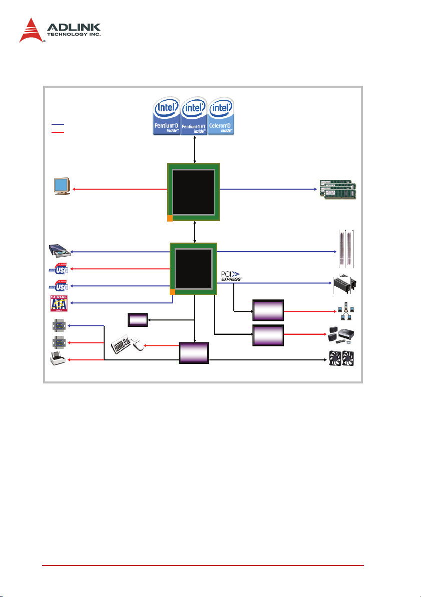
1.1 Block Diagram
Onboardȱconnectorȱorȱslot
ConnectorȱonȱrearȱI/O
IntelȱP4 LGAȬ775
FSBȱ533/800/1066MHz
MȬȬ
945
M
945
MicroATXȱIndustrialȱMB
MicroATXȱIndustrialȱMB
AnalogȱCRT
RSȬ232
RSȬ232
LPT
GMA950
IȱchannelȱUltraATAȱ100
4ȱUSBȱ2.0ȱports
4ȱUSBȱ2.0ȱports
4ȱSATA300ȱports
BIOS
BIOS
DualȬChannelȱDDR2 533/667MHz
X1 PCIȱExpress
Azalia
CPU/systemȱFanȱSpeedȱControl
PS/2ȱKB/MS
Intel
Intel
5G
94945G
DMIȱ2GB/s
Intel
Intel
ICH7
ICH7
LPC
SuperȱI/O
SuperȱI/O
IT8712F
IT8712F
Figure 1-1: Block Diagram
PCIȱ33MHz
PCIeȱGbEȱȱȱȱȱȱȱȱ
PCIeȱGbEȱȱȱȱȱȱȱȱ
Intelȱ82573E
Intelȱ82573E
Channel
22ȬȬChannel
HDȱAudio
HDȱAudio
10/100/1000Mbps
2Introduction
Page 11

1.2 Features
Advanced Processor Support
The M-945 motherboard comes with a Socket T designed for the
Intel processors in the LGA775 package. The motherboard features a powerful 1066/800/533 MHz Front Side Bus (FSB), supports the Intel
compatible with Intel
Promoting high-performance computing and energy-efficiency, the
M-945 supports the next-generation Intel
®
tium
4/Intel® Celeron® D CPU built in the 65 nm process technology. The M-945 backs dual-core processing when deployed with a
CPU containing two physical cores and dedicated L2 caches to
meet the ever-increasing demands of industrial computing.
Intel® 945G Express chipset
®
Hyper-Threading Technology, and is fully
®
05B/05A or 04B/04A processors.
®
Pentium® D/Intel® Pen-
The Intel® 945G Express chipset, featuring the Intel® 945G graphics memory controller hub (GMCH) and the Intel
®
ICH7 I/O con-
troller hub, provides the vital interfaces for the motherboard. The
®
Intel
945G comes with the Intel® Graphics Media Accelerator
950—an integrated graphics engine for enhanced 3D/2D graphics
rendering and video capabilities. The GMCH also provides the
interface for the processor and system memory.
The Intel
controller hub that provides the essential interfaces for the PCI
Express
®
ICH7 Southbridge is the seventh generation of Intel I/O
®
, USB 2.0, and SATA II.
Dual-channel DDR2 memory
To meet the requirements of memory-intensive applications, the
M-945 has a dual-channel memory architecture supporting DDR2
667/533/400 MHz DIMMs. The high-bandwidth memory specification, peaking at bandwidths of up to 10.7 GB/s, meets the requirements of the latest 3D graphics, multimedia, and network
application, and boosts system performance by eliminating bottlenecks.
Introduction 3
Page 12

Intel® Graphics Media Accelerator 950
The Intel® Graphics Media Accelerator (GMA) 950 revolutionizes
integrated graphics with new capabilities that provide significant
increase in graphics performance. With support for DirectX
®
9
hardware acceleration, 400 MHz core clock, and up to 224 MB of
video memory, the Intel GMA 950 provides a cost-effective and
high-performance graphics solution. The Intel GMA comes with
the dual-independent display technology, enabling different contents to be displayed on two separate display terminals or a single
content stretched across two display devices for expanded workspace.
Gigabit Ethernet
The motherboard is equipped with the Intel® 82573E—a PCI
Express
plete network solution. Utilizing the wide PCI Express
®
-bus based gigabit Ethernet controller that offers a com-
®
bandwidth,
the gigabit LAN controller allows up to 1 Gbps of data transfer rate
for superior network communications.
PCI Express
The M-945 fully supports the PCI Express® technology with two
PCI Express
accelerates the PCI bus speed and features smaller connectors
for additional board surface space. PCI Express
®
®
x1 slots. PCI Express® is latest I/O standard that
®
allows faster
data transfers through point-to-point serial interconnections
between devices and by carrying data in packets. This high-speed
interface is software-compatible with existing PCI specifications.
Serial ATA II technology
Storage is efficient and secured with the Serial ATA II interface.
Taking cue from the Intel
Serial ATA II devices capable of reading/writing data at up to 3
Gbps. The SATA specification improves chassis airflow via thinner
and more flexible cables with lower pin count, reduces voltage
requirement, and delivers up to 300 MB/s data transfer rate.
®
ICH7, the M-945 supports up to four
4Introduction
Page 13

Universal Serial Bus (USB) 2.0
The M-945 incorporates the Universal Serial Bus (USB) 2.0 specification that increases peripheral connection speed from 12 Mbps
(USB 1.1) to a fast 480 Mbps. USB 2.0 is backward compatible
with USB 1.1.
Hardware monitoring
A built-in, proactive hardware monitoring system in the ASIC monitors the CPU temperature, system fan rotations, and voltage levels to prevent overheating and/or component damage, effect a
timely failure detection, and ensure stable supply of current for
critical motherboard components.
Watchdog Timer
The watchdog timer (WDT) monitors system operations based on
user-defined configurations. The WDT can be programmed for different time-out periods, such as from 1 to 255 seconds or from 1 to
255 minutes. The WDT generates a reset signal, then a reset
request, after failure to strobe it within the programmed time
period. A register bit may be enabled to indicate if the watchdog
timer caused the reset event.
The WDT register is cleared during the power-on sequence to
enable the operating system to take appropriate action when the
watchdog generates a reboot.
Software
The M-945 is compatible with all major operating systems.
ADLINK provides additional drivers for ADLINK peripherals. Hardware and software drivers may be found in the ADLINK All-in-One
CD.
Introduction 5
Page 14
1.3 Mechanical Drawing
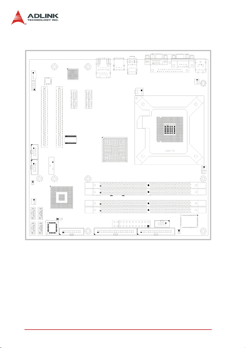
Figure 1-2: Mechanical Drawing
6Introduction
Page 15
1.4 Components and Connectors
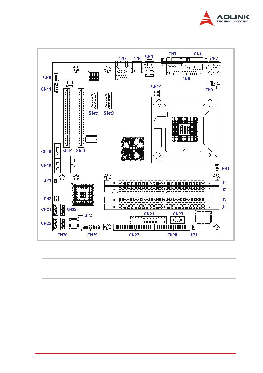
Figure 1-3: Layout
NOTE Refer to the table on the next page for a description of the
Introduction 7
connectors and jumper.
Page 16

Item Connector Description
1 FN1 4-pin CPU fan connector
2 FN2 3-pin System fan connector
3 FN3 3-pin System fan connector
4 J1 240-pin DDR2 DIMM slot 1
5 J2 240-pin DDR2 DIMM slot 2
6 J3 240-pin DDR2 DIMM slot 3
7 J4 240-pin DDR2 DIMM slot 4
8 Slot1 PCI slot 1
9 Slot2 PCI slot 2
10 Slot3 PCI Express x1 slot 1
11 Slot4 PCI Express x1 slot 2
12 CN1 Audio port
13 CN2 PS/2 keyboard/mouse port
14 CN3 VGA port
15 CN4 Serial port (COM 1)
16 CN5 USB 2.0 ports 3 and 4
17 CN6 Parallel port (LPT)
18 CN7 LAN port (RJ-45) + USB 2.0 ports 1 and 2
19 CN8 CD-ROM Audio-in connector
20 CN11 Front panel audio connector
21 CN12 4-pin ATX 12V power connector
22 CN18 USB port connector (for USB 2.0 ports 5 and 6)
23 CN19 USB port connector (for USB 2.0 ports 7 and 8)
24 CN21 Serial ATA connector (SATA 1)
25 CN22 Serial ATA connector (SATA 3)
26 CN23 Serial port connector (COM 2)
27 CN24 24-pin ATX power connector
28 CN25 Serial ATA connector (SATA 2)
29 CN26 Serial ATA connector (SATA 4)
30 CN27 40-pin IDE connector
31 CN28 34-pin floppy disk drive connector
32 CN29 20-pin system panel connector
33 JP1 Chassis intrusion connector
34 JP2 CMOS clear jumper
35 JP4 Temperature sensor connector
8Introduction
Page 17

1.5 Specifications
Form Factor MicroATX form factor: 244 mm x 244 mm (9.6" x 9.6")
CPU • LGA775 socket supports Intel
®
Pentium® 4/Intel® Celeron® D processor
Intel
• Supports Intel® Hyper-Threading Technology
• Front side bus: 1066/800/533 MHz
Host Memory • Dual-channel memory architecture
• Four 240-pin DIMM sockets support up to 4 GB of system
memory using unbufferred non-ECC 667/533/400 MHz
DDR2 DIMMs
Chipset
Northbridge: Intel
Southbridge: Intel
®
945G
®
ICH7
Gigabit Ethernet • Integrated Intel® 82573E network controller supports 10/
100/1000Base-T gigabit Ethernet on PCI Express® x1 bus
• Speed and link LEDs on the RJ-45 port
Graphics
Display
•Intel® Graphics Media Accelerator (GMA) 950 with
enhanced 2D/3D graphics acceleration
• Up to 224 MB shared video memory
• Resolution up to 2048 x 1536 @ 85 Hz refresh
Expansion slots
2 x PCI Express
®
x1
2 x PCI
Storage 4 x Serial ATA 3 Gb/s connectors
1 x UltraATA 100/66/33 connector
BIOS • Phoenix Award system BIOS supporting PnP, APM, DMI,
ACPI, and multi-device booting
• Write-protection and field upgradeable
USB Interface • Four USB 2.0 ports at the rear I/O panel
• Two USB 2.0 connectors at midboard support up to four
additional USB 2.0 ports
• Up to 480 Mbps data transfer rate
• Backward-compatible with USB 1.1 specification
Rear panel I/O
ports
1 x PS/2 keyboard port
1 x PS/2 mouse port
1 x VGA port
1 x Serial port (COM1)
1 x Parallel port (LPT)
1 x LAN (RJ-45) port
4 x USB 2.0/1.1 ports
3 x audio jacks (Line In/Line Out /MIC In)
®
Pentium® D/
Introduction 9
Page 18

Internal
connectors
Environment • Operating temperature: 0°C – 60°C (with proper airflow
Safety
Certificates and
Tests
1 x Floppy disk drive connector
1 x IDE connector
4 x Serial ATA connectors
2 x USB 2.0 connectors
1 x COM connector
3 x fan connectors (CPU, chassis, and system)
Front panel system connector
Front panel audio connector
Chassis intrusion connector
Audio-in connector for optical drive
1 x 24-pin ATX power connector
1 x 4-pin ATX 12 V power connector
and active heatsink)
• Storage temperature: -40°C – 85°C
• Humidity: 5% – 95% non-condensed
• Shock: 30G peak-to-peak, 10 ms, non-operation
•Vibration:
Non-operation: 6G, 10 Hz –1000 Hz, random
Operation: 0.5 G, 510 Hz –1000 Hz, random
CE certified
FCC Part 15 class
UL-1950, CSA-950, and VDE EN 60 950/IE950
10 Introduction
Page 19
1.6 Package contents
Before unpacking, check the shipping carton for any damage. If
the shipping carton and/or contents are damaged, inform your
dealer immediately. Retain the shipping carton and packing materials for inspection. Obtain authorization from the dealer before
returning any product to ADLINK.
Check if the following items are included in the package.
X M-945 industrial motherboard
X COM (Serial) port module
X Floppy disk drive cable
X UltraATA 100 IDE cable
X 2 x SATA cables
X Dual-plug Serial ATA power cable
X ADLINK All-in-One driver CD
X User’s manual
NOTE The M-945 OEM version package may contain a non-
standard configuration, unique functionality, or different
packaging according to configuration requests.
CAUTION The M-945 single board computer must be protected
from static discharge and physical shock. Never remove
any of the socketed parts except at a static-free workstation. Use the anti-static bag shipped with the product to
handle the board. Wear a grounded wrist strap when installing and/or servicing.
Introduction 11
Page 20

12 Introduction
Page 21
2 Connectors and Jumpers
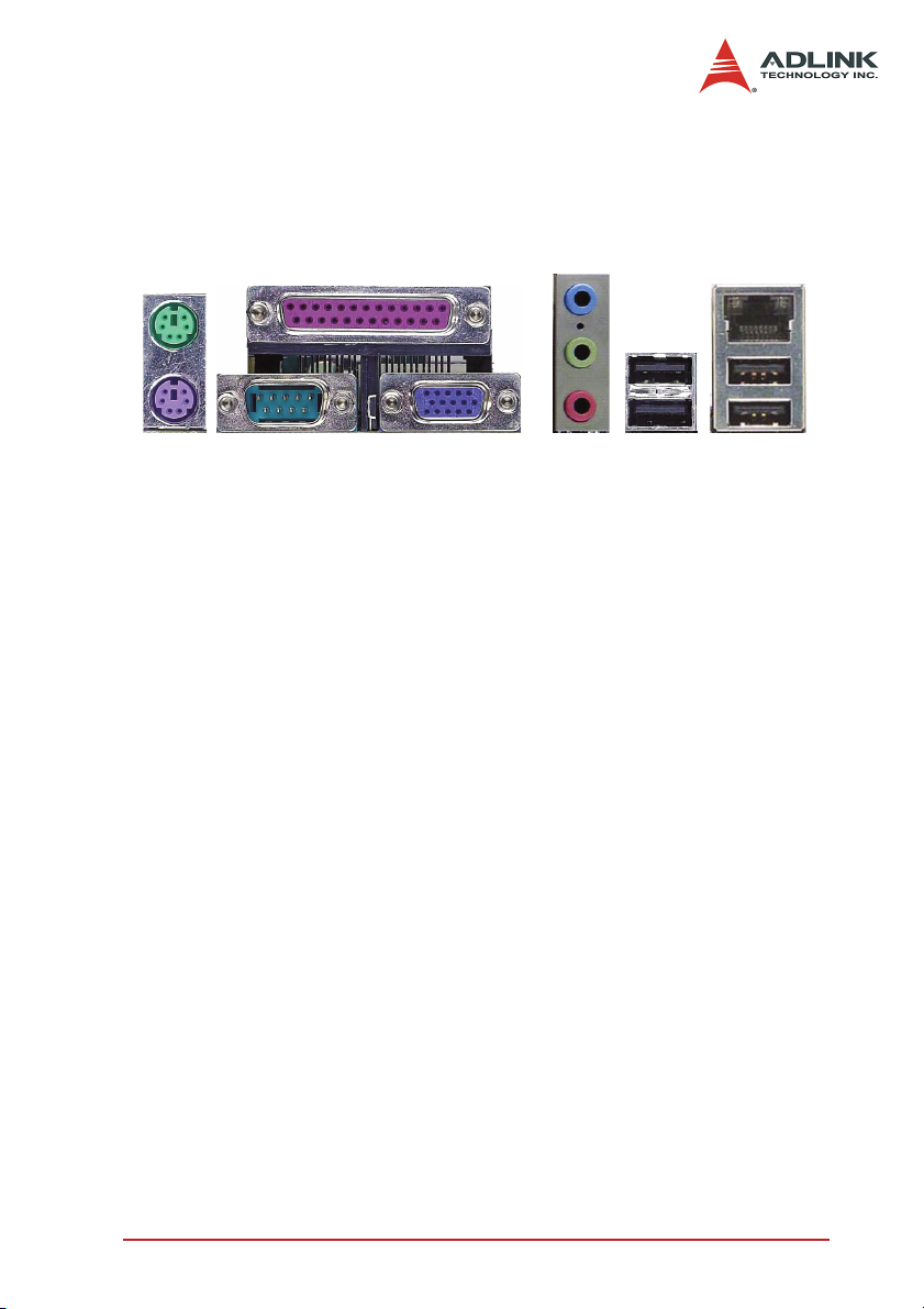
2.1 Rear panel connectors
1
2
1. PS/2 mouse port (green). Connects a PS/2 mouse.
2. PS/2 keyboard port (purple). Connects a PS/2 key-
3. Parallel port. This 25-pin port connects a parallel
4. Serial port. The 9-pin COM1 port connects serial
5. VGA port. This 15-pin port connects to a CRT or LCD
6. Audio I/O port. The three-jack audio I/O supports Line-
7. USB 2.0 ports 3 and 4. These high-speed USB ports
4567
board.
printer, scanner, or other parallel devices.
devices.
monitor.
In, Line-Out, and Mic-In functions. The Line-In jack
(blue) connects to an audio source such as tape recorders, etc. The green Line-Out port connects a speaker or
headphone, while the pink Mic-In jack connects a microphone.
are available for connecting USB devices.
3
8
9
Connectors and Jumpers 13
Page 22
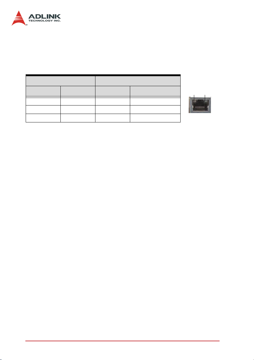
8. LAN port (RJ-45). This port allows gigabit connection to
a Local Area Network (LAN) using a network hub. The
LAN port comes with an activity/link and speed LED.
Refer to the table below for the LAN port LED indications.
ACD/LINK LED SPEED LED
Status Description Status Description
OFF No Link OFF 10 Mb connection
GREEN Linked ORANGE 100 Mb connection
BLINKING Data Activity GREEN 1 Gb connection
9. USB2.0 ports 1 and 2. These high-speed USB ports are
available for connecting USB devices.
ACT/LI NK
LED
RJ45
SPEED
LED
14 Connectors and Jumpers
Page 23
2.2 Connector Pin Assignments
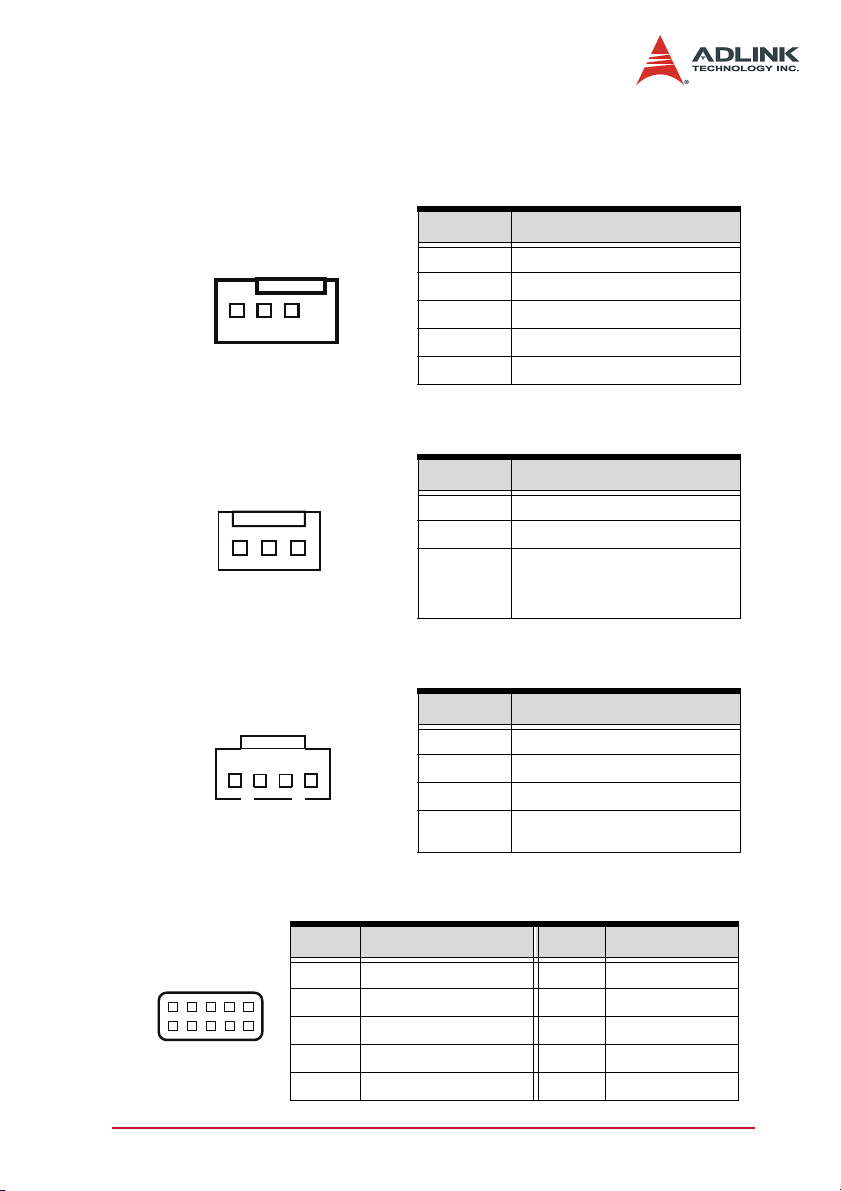
CPU Fan Connector (FN1)
Pin # Signal
1
GND
2 Fan power (+12V)
3 Fan Tachometer
4 Fan Control (optional)
System Fan Connector (FN2, FN3)
Pin # Signal
1
13
CD-ROM Audio-In Connector (CN8)
GND
2 Fan power (+12V)
Pin # Signal
1 Left channel
14
2 GND
3 GND
4 Right channel
Front Panel Audio Connector (CN11)
Pin # Signal Pin # Signal
2
1
Connectors and Jumpers 15
10
9
1 MIC-In left channel 2 Analog GND
3 MIC-In right channel 4 RSV
5 Line-In left channel 6 Analog GND
7 RSV 8 Analog GND
9 Line-In right channel 10 Analog GND
Page 24
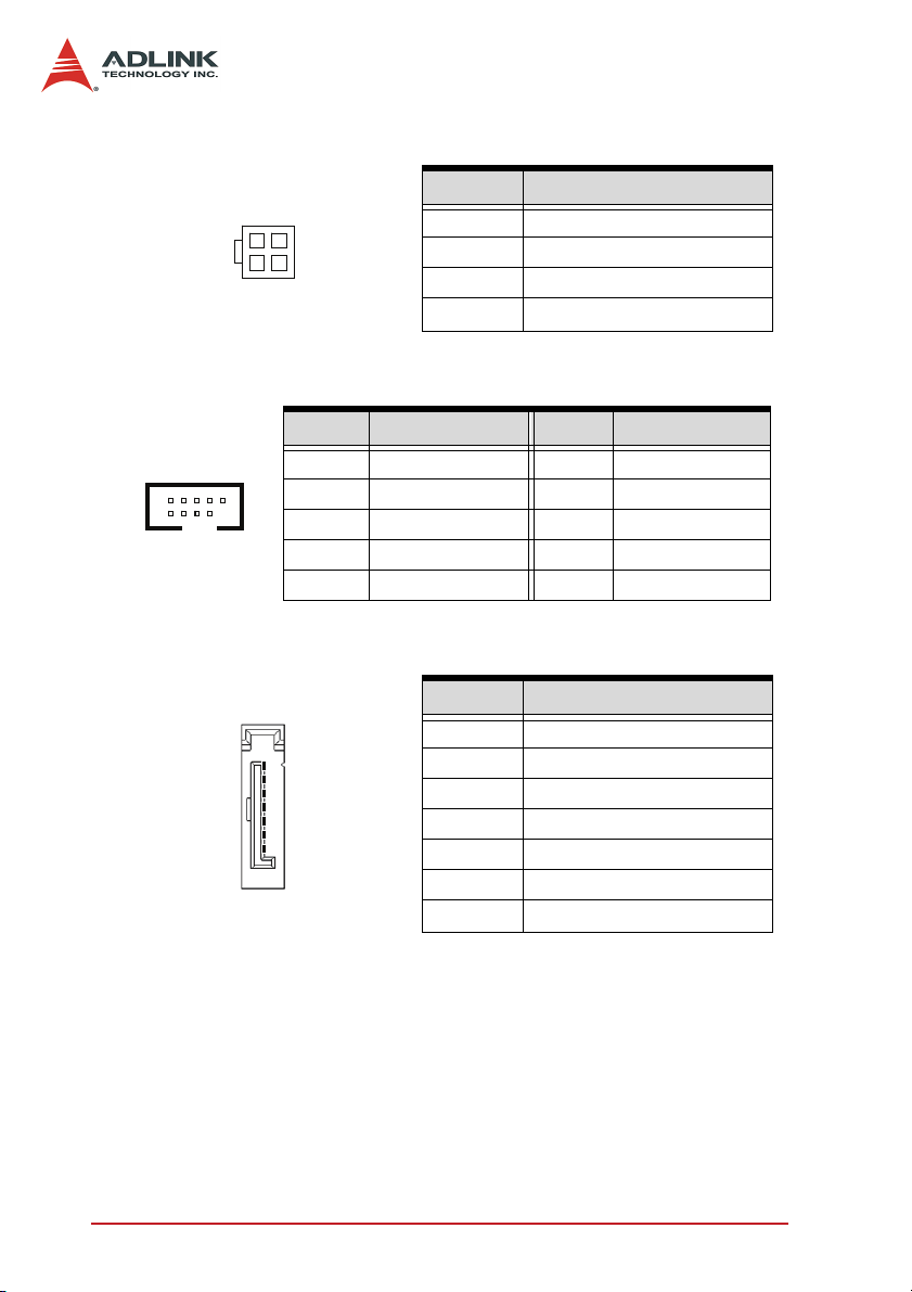
ATX 12V Power Connector (CN12)
Pin # Signal
4
2
1 GND
2 GND
31
3 +12V DC
4 +12V DC
USB 2.0 Connectors (CN18, CN19)
Pin # Signal Pin # Signal
2
10
1 +5V 2 +5V
3 Data 1 - 4 Data 2 -
1
5 Data 1 + 6 Data 2 +
7 GND 8 GND
9 Key 10 NC
Serial ATA Connectors (CN21, CN22, CN25, CN26)
Pin # Signal
1 GND
1
7
2 TXP (A +)
3 TXN (A -)
4 GND
5 RXN (B -)
6 RXP (B +)
7 GND
16 Connectors and Jumpers
Page 25
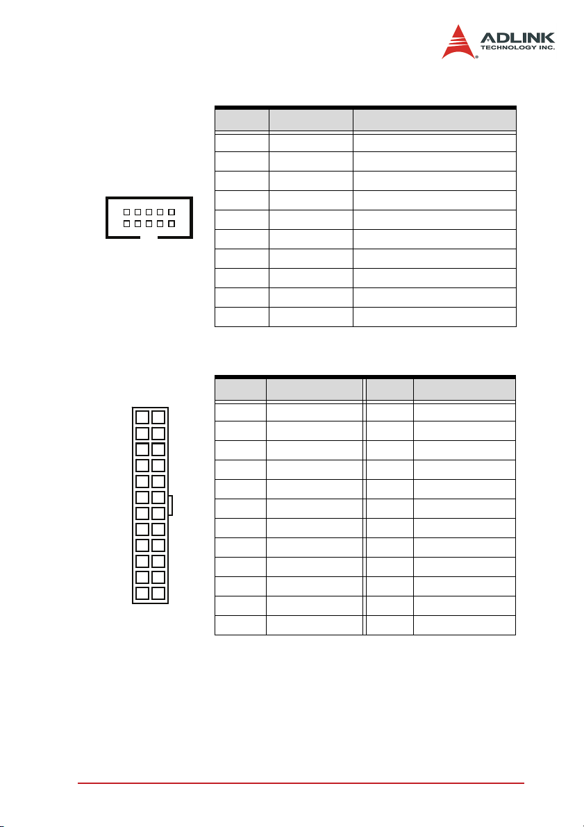
COM2 connector (CN23))
Pin # Signal Functions
1 DCD Data Carrier Detect
2 RXD Receive Data
610
3 TXD Transmit Data
4 DTR Data Terminal Ready
5 GND Ground
15
6 DSR Data Set Ready
7 RTS Request to Send
8 CTS Clear to Send
9 RI Ring Indicate
10 NC No Connect
ATX power connector (CN24)
Pin # Signal Pin # Signal
12
1
24
13
1 3.3V 13 3.3V
2 3.3V 14 - 12V
3 GND 15 GND
4 5V 16 PS On
5 GND 17 GND
6 5V 18 GND
7 GND 19 GND
8 Power Good 20 - 5V
9 5VSB 21 5V
10 12V 22 5V
11 12V 23 5V
12 3.3V 24 GND
Connectors and Jumpers 17
Page 26

IDE connector (CN27)
Pin # Signal Pin # Signal
1 Reset IDE 2 Ground
3 Host data 7 4 Host data 8
5 Host data 6 6 Host data 9
7 Host data 5 8 Host data 10
9 Host data 4 10 Host data 11
11 Host data 3 12 Host data 12
13 Host data 2 14 Host data 13
15 Host data 1 16 Host data 14
17 Host data 0 18 Host data 15
19 Ground 20 NC
21 DRQ0 / DRQ1 22 Ground
23 Host IOW 24 Ground
25 Host IOR 26 Ground
27 IOCHRDY 28 Host ALE
29 DACK0 / DACK1 30 Ground
31 IRQ14 / IRQ 15 32 No connect
33 Address 1 34 No connect
35 Address 0 36 Address 2
37 Chip select 0 38 Chip select 1
39 Activity 40 Ground
18 Connectors and Jumpers
Page 27
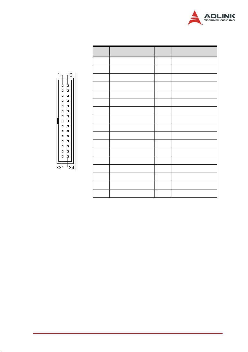
Floppy disk drive connector (CN28)
Pin # Signal Pin # Signal
1 GND 2 Extended Density
3 GND 4 No Connect
5 NC 6 Data Rate
7 GND 8 Index
9 GND 10 Motor A Select
11 GND 12 Drive B Select
13 GND 14 Drive A Select
15 GND 16 Motor B Select
17 GND 18 Step Direction
19 GND 20 Step Pulse
21 GND 22 Write Data
23 GND 24 Write Gate
25 GND 26 Track 0
27 GND 28 Write Protect
29 GND 30 Read Data
31 GND 32 Side 1
33 GND 34 Disk Change
Connectors and Jumpers 19
Page 28
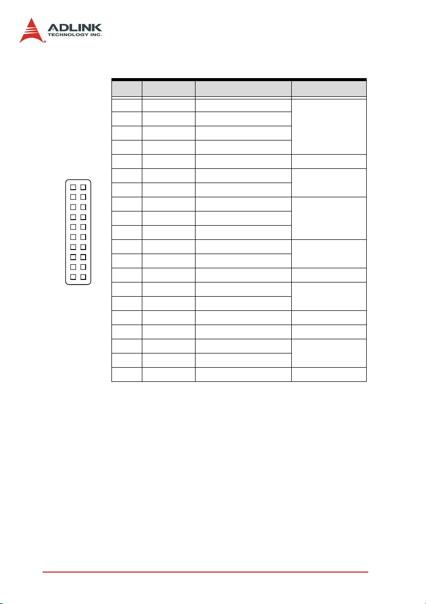
System panel connector (CN29))
Pin # Signal Function Pin Group
1 WDSPK Speaker signal
2 NC
3 NC
4 +5V Power
5 NC
6 GND Ground
1
10 20
11
7 KEYLOCK Keyboard lock
8 PLED Power LED signal
10 +5V Power LED pull-up
11 GND Ground
12 RESETBT RESET signal
13 NC
14 GND Ground
15 POWERBT Power-on signal
16 NC
17 NC
18 HDDLED Hard Disk LED signal
19 +5V Hard Disk LED pull-up
20 NC
Chassis Speaker
Key Lock
Power LED9 NC
RESET button
Power on button
Hard Disk LED
20 Connectors and Jumpers
Page 29
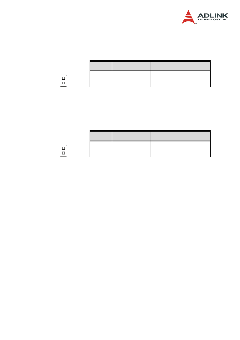
Chassis intrusion connector (JP1)
Signal is connected to a limit switch sensor of the chassis to detect
if the case is opened or closed.
1
1 CASEOPEN# Case Open Signal
2 GND 2
Pin # Signal Functions
2
Temperature sensor connector (JP4)
1
2
Pin # Signal Functions
1 TGND Thermal ground
2 VTIN Thermal voltage input
Connectors and Jumpers 21
Page 30
2.3 Jumper
Clear RTC RAM (JP2)
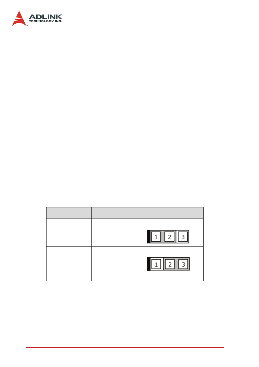
The JP2 jumper enables you to clear the Real Time Clock (RTC)
RAM stored in the CMOS chip. You may clear the CMOS memory
of date, time, and system passwords by erasing the CMOS RTC
RAM data. The button cell battery on the motherboard powers the
RAM data in CMOS, including system setup information such as
system passwords.
To erase the RTC RAM using the JP2 jumper:
1. Turn the system off, then unplug the power cord.
2. Remove the onboard cell battery.
3. Remove the jumper cap from pins 1-2 (default), then
short pins 2-3 for about 10 seconds.
4. Replace the jumper cap on pins 1-2.
5. Re-install the cell battery, plug the power cord then turn
the computer on.
6. Enter the BIOS Setup during the boot sequence to reenter RTC data such as time, date, etc.
RTC status Connection JP2
Normal 1 – 2
Clear CMOS 2 – 3
22 Connectors and Jumpers
Page 31
3 Getting Started
This chapter provides information on how to install components to
the M-945 motherboard. Sections discussing the BIOS setup and
operating system installation are also found in this chapter.
3.1 Installing the CPU
The M-945 supports the Intel® Pentium® D/Intel® Pentium® 4/
®
Intel
Celeron® D processor via the surface mount LGA775
socket (Socket T).
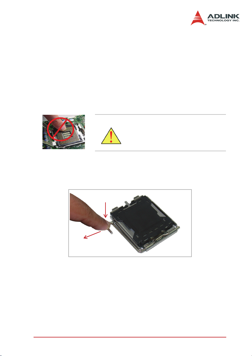
WARNING Do not touch socket contacts. Dam-
To install the CPU:
1. Press the load lever (A), then disengage it from the
retention tab (B).
A
B
aging the contacts voids the product
warranty. Follow the installation instructions carefully to avoid damaging to motherboard components.
Getting Started 23
Page 32
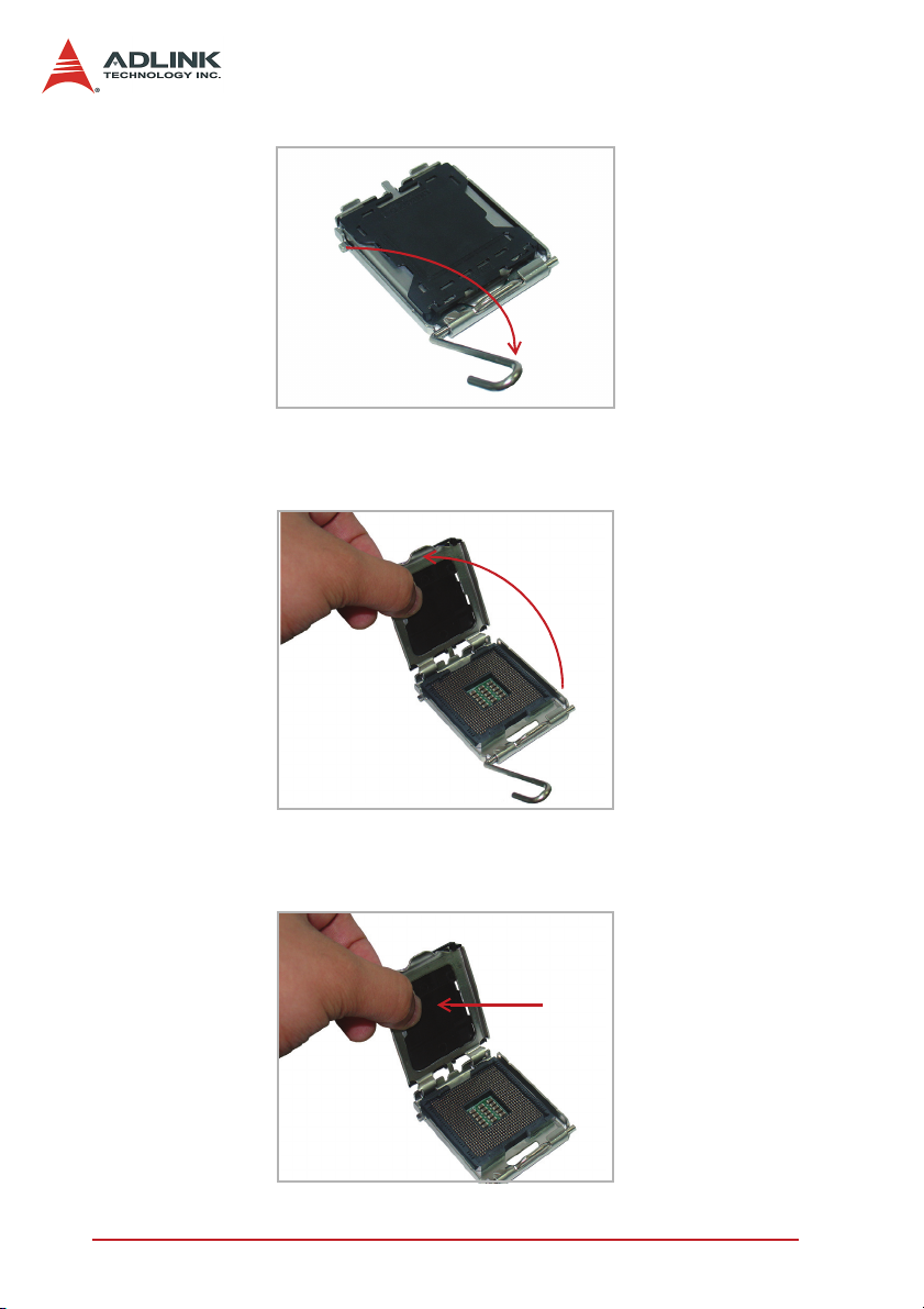
2. Lift and rotate the load lever to a 135° angle.
3. Lift the load plate to a 100° angle using your thumb and
forefinger.
4. Use your thumb to push and remove the protective
socket cover (plastic) from the load plate.
24 Getting Started
Page 33
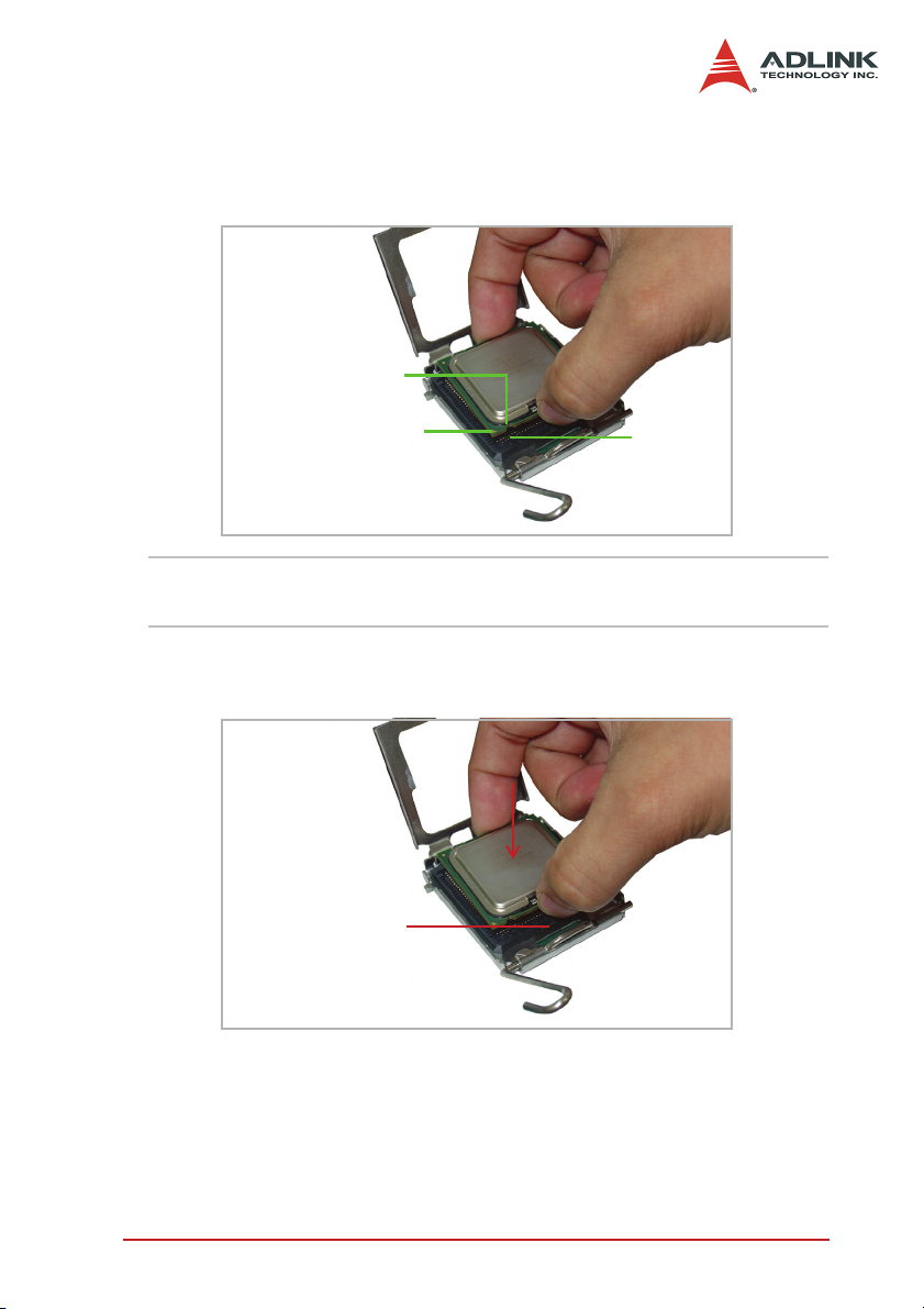
5. Position the CPU over the socket, then match the
notches on the CPU side with the alignment keys on the
socket. The golden triangle on the CPU must be positioned on the bottom-left corner of the socket.
Notch
Golden triangle
Alignment
key
WARNING The CPU fits the socket in only one orientation. DO NOT
force the CPU into the socket to avoid damaging them.
6. Carefully place the CPU on the socket in a vertical
motion. The socket has tabs that accommodate your fingers during installation.
Socket tab
Getting Started 25
Page 34
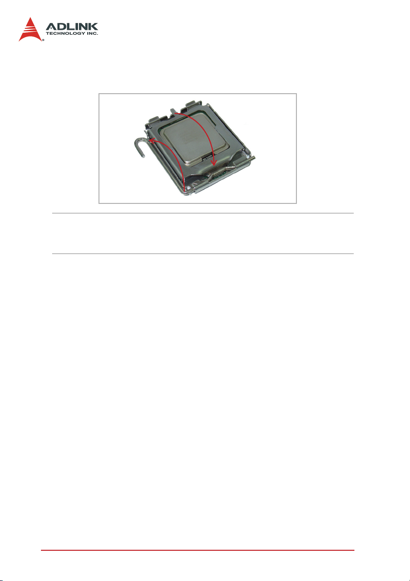
7. Close the load plate (A), then fasten the load lever on
the retention tab (B).
A
B
NOTE In order to boot up the system with a newly-installed
CPU, standby power must not be applied to the board before installation.
26 Getting Started
Page 35
3.2 Installing the CPU Fan
When you buy a boxed Intel CPU, a certified CPU fan and heatsink assembly with installation instruction comes standard with the
package. If the CPU fan installation procedures presented here
are inconsistent with the installation procedures you obtained from
the Intel CPU package, follow the latter.
If you intend to purchase a separate CPU fan and heatsink assembly, make sure that the selected model is recommended by Intel.
For more information, go to tap://www.intel.com.
CAUTION The CPU requires a chassis with an airflow inlet and max-
imum internal ambient temperature of 38°C. A especiallydesigned CPU fan and heatsink must be installed before
using the motherboard. Failure to install a CPU fan and
heatsink may damage the motherboard and/or the CPU.
To install the CPU fan:
1. Apply thermal grease evenly on top of the installed CPU.
2. Lower the CPU fan to the CPU, then secure it using the
provided attachments or screws.
3. Connect the CPU fan cable to the CPU fan connector on
the motherboard labeled FN1.
Getting Started 27
Page 36
3.3 Installing the Memory Module
The M-945 supports up to 8 GB of DDR2 800/667/533 MHz
memory modules via four DDR2 DIMM sockets. A DDR2 module
has a 240-pin footprint compared to the legacy 184-pin DDR
DIMM. DDR2 modules are notched to facilitate correct installation
on the DIMM sockets.
Memory Configuration Options
The M-945 allows you to install 256 MB, 512 MB and 1GB unbuffered non-ECC DDR2 DIMMs into the DIMM sockets following
these configuration options:
X Channel A: DIMM1 (J1) and DIMM2 (J2)
Channel B: DIMM3 (J3) and DIMM4 (J4)
X For dual-channel configuration, the total size of memory
module(s) installed per channel must be the same
(J1 + J2 = J3 + J4).
X It is recommended that you install DIMMs with the same
CAS latency. For maximum compatibility, install memory
modules with the same brand, model, and/or rating.
To install a memory module:
1. Locate the DIMM slots on the motherboard (J1, J2, J3,
J4).
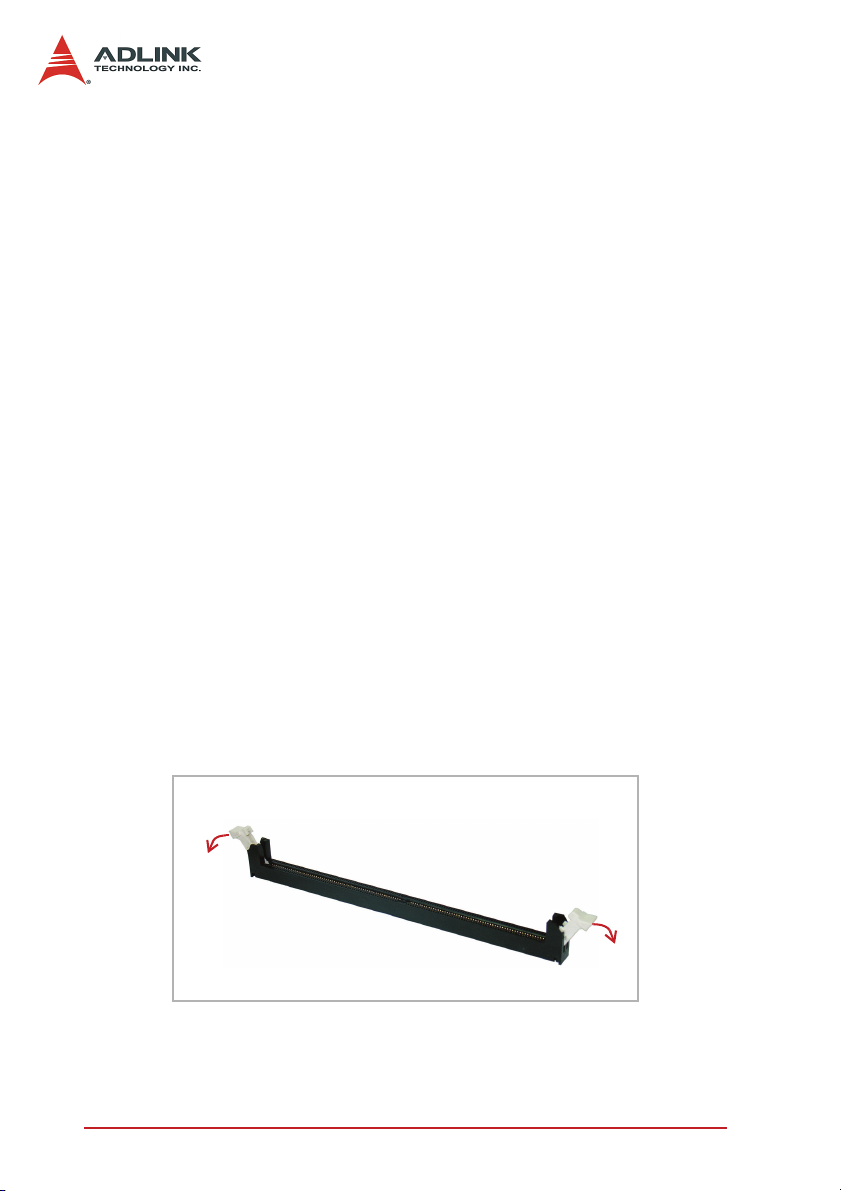
2. Press the socket’s retaining clips outward to unlock.
28 Getting Started
Page 37
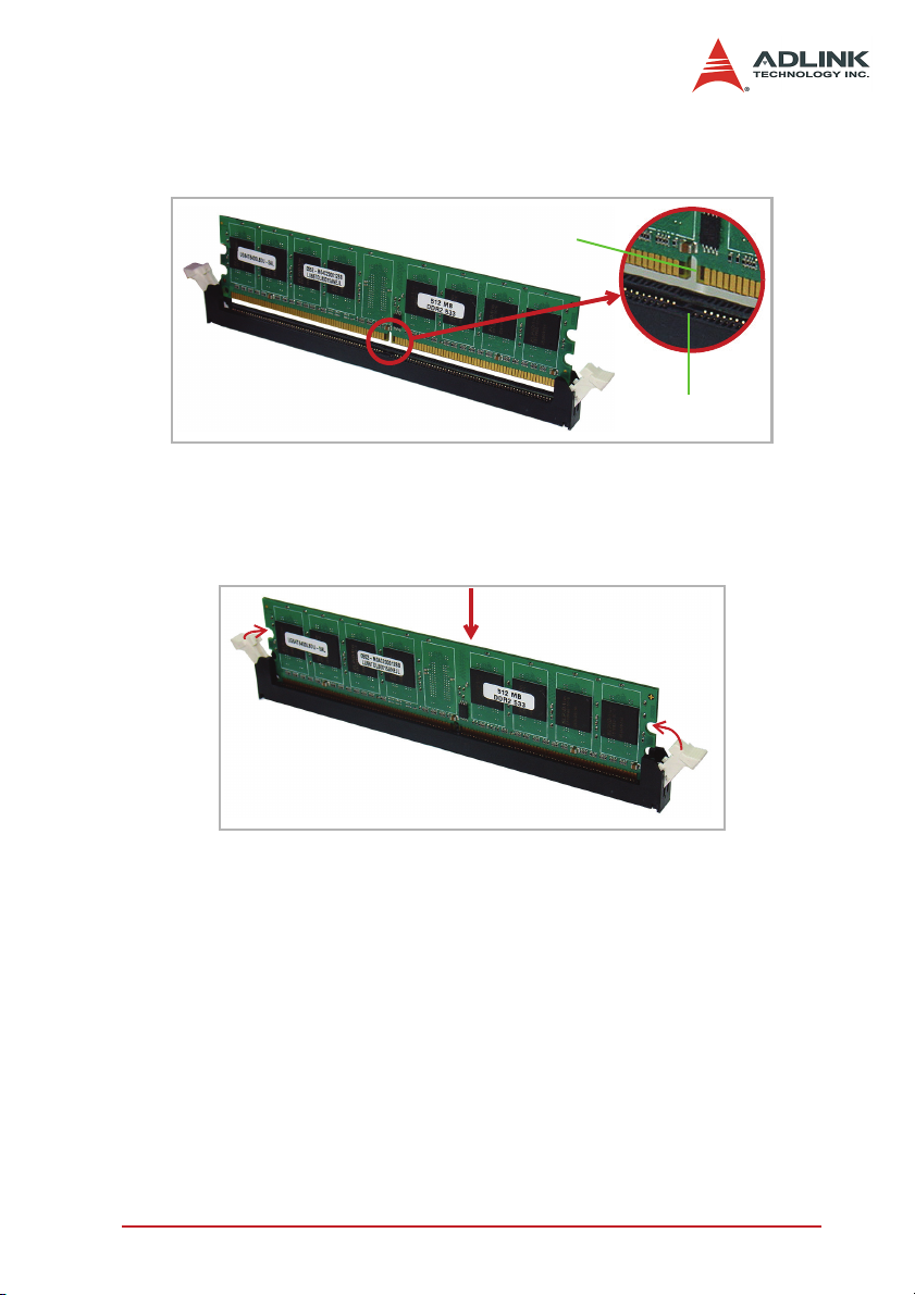
3. Align the memory module on the socket making sure
that the notch matches the break on the socket.
Notch
Break
4. Insert the module firmly into the slot until the retaining
clips snap back inwards and the module is securely
seated.
Getting Started 29
Page 38

3.4 BIOS Configuration Overview
The M-945 BIOS Setup features several, separately configurable
parameters. These parameters are selected and configured via
the built-in setup utility. System configuration settings are saved in
a portion of the battery-powered RAM in the real-time clock
device. The BIOS uses these settings to initialize the system during startup or reset. The configuration settings are protected by a
checksum word for system integrity.
To access the BIOS Setup, press Del during the system boot
sequence. The BIOS Setup configuration screen appears.
Setup parameters are divided into categories. The available categories are listed in the main menu. The parameters within the
highlighted (current) category are listed in the bottom portion of
the BIOS Setup screen. Context sensitive help is displayed in the
right portion of the screen for each parameter.
Use the keyboard arrow keys to navigate through the items and/or
select a category from the menu. To display a submenu, highlight
the category, then press Enter.
For detailed information on the BIOS Setup and other utilities,
refer to the BIOS Setup manual.
30 Getting Started
Page 39

3.5 Installing the Operating System
The M-945 supports most mainstream operating systems including Windows
®
XP/2000/Server 2003 and Linux. For more information, refer to the documentation provided by the operating system
vendor.
Most operating systems requires installation from a floppy or optical disk drive. These devices must be configured, installed, and
tested with the supplied drivers before attempting to install a new
operating system.
Consult the release notes and installation documentation provided
by the operating system vendor for documentation discrepancies
and/or compatibility issues, problems, and solutions.
When you are ready to install the operating system, use the BIOS
Setup to assign the first boot device depending on the media used
by the OS installer. For example, if the OS installation came on a
bootable floppy disk, set the floppy drive as the first boot device,
save the configuration setting, then reboot the system. Make sure
you insert the installation floppy disk in the floppy drive. When the
OS installer is in a non-bootable optical disk, you may have to boot
the system using a bootable floppy disk with the proper CD/DVDROM drivers to access the optical drive.
Follow the installation screen instructions to proceed. Make sure
you select the correct device types and settings, when prompted.
Refer to the appropriate hardware manuals for specific device
types and compatibility.
After OS installation is completed, reboot the system, then set the
boot device sequence from the Boot menu in the BIOS Setup.
Getting Started 31
Page 40

3.6 Installing Peripheral Devices
Installed peripheral devices are automatically configured by the
BIOS during the boot sequence. Plug and play expansion cards
that conform with the M-945 specifications are supported.
32 Getting Started
Page 41
4 Installing Device Drivers
This chapter provides information on basic driver installation for
systems running on Windows
for non-Windows
®
operating systems, refer to the instructions
®
2000/XP. When installing drivers
inside the ADLINK All-in-One CD. The drivers are located in the
following directories of the ADLINK All-in-One CD:
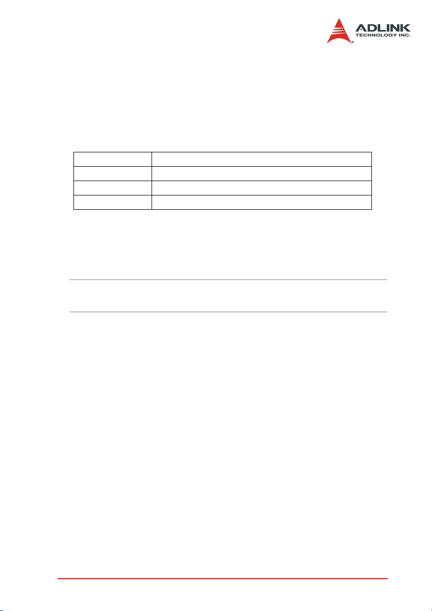
Chipset driver \Industrial Motherboard\M-945_946\Chipset\
Display driver \Industrial Motherboard\M-945_946\VGA\
LAN driver \Industrial Motherboard\M-945_946\Ethernet\
Audio driver \Industrial Motherboard\M-945_946\Audio
4.1 Intel® 945G Chipset Drivers
This section describes the installation of the Intel® 945G chipset
driver on systems operating on Windows
NOTE Take note of the location of the Windows® 2000/XP direc-
tory before installing the driver.
1. Check if your system meets the minimum requirements.
Windows
®
2000/XP OS must be fully installed and running normally on the system before installing the chipset
drivers.
2. Close all applications.
3. Check that the files are stored in an integrated application setup program. This program is designed for a Windows 2000/XP program that allows the INF files to be
installed.
4. Locate the directory X:\Industrial Motherboard\M-
945_946\Chipset\ from the ADLINK All-in-One CD,
select the operating system, then start the installation by
clicking on the Setup.exe file.
®
2000/XP.
5. When the initial installation window appears, click Next
to display the license agreement. When prompted, click
Yes to continue.
Installing Device Drivers 33
Page 42

NOTE Clicking No on the license agreement terminates the in-
stallation.
6. Click Next on the Readme Information screen to begin
installing the INF files.
7. When installation is done, click Finish. Restart the sys-
tem when prompted.
8. After restart, follow screen instructions to complete
installation. Windows displays a found new hardware
window and automatically installs the required drivers. If
the New Hardware Found dialog box appears and
prompts you to locate the location of the drivers, point it
to the relevant Windows directory.
9. Restart the system when prompted.
34 Installing Device Drivers
Page 43

4.2 Display Drivers
This section tells you how to install the Intel® Graphics Media
Accelerator (GMA) 950 drivers on Windows
®
2000/XP systems.
To install the display drivers:
1. Place the ADLINK All-in-One CD to the optical drive.
2. Locate the display drivers from the directory X:\Indus-
trial Motherboard\M-945_946\VGA\, then double-click
on the win2k_xp141950.exe file to start installation.
3. Follow screen instructions to complete installation, then
restart the system, when prompted.
4. After installation, you may change the display properties
from the Windows
®
Control Panel.
4.3 LAN Drivers
Follow these instructions to install the LAN driver on Windows
2000/XP systems.
1. Place the ADLINK All-in-One CD to the optical drive.
2. Locate the LAN drivers from the directory X:\Industrial
Motherboard\M-945_946\Ethernet\, then double-click
on the PRO2KXP.exe file to start installation.
3. Follow screen instructions to complete installation, then
restart the system, when prompted.
4. After installation, you may change the network proper-
ties from the Windows
®
Control Panel.
®
Installing Device Drivers 35
Page 44

4.4 Audio Drivers
Follow these instructions to install the audio driver on Windows
2000/XP systems.
1. Place the ADLINK All-in-One CD to the optical drive.
2. Locate the audio drivers from the directory X:\Industrial
Motherboard\M-945_946\Audio\, then double-click on
the SETUP.exe file to start installation.
3. Follow screen instructions to complete installation, then
restart the system, when prompted.
®
After installation, you may change the audio properties from the
Windows
®
Control Panel.
36
Page 45

Important Safety Instructions
Read and follow all instructions marked on the product and in the
documentation before operating the system. Retain all safety and
operating instructions for future use.
X Read these safety instructions carefully.
X Keep this user’s manual for future reference.
X The equipment should be operated in an ambient tempera-
ture between 0
X The equipment should be operated only from the type of
power source indicated on the rating label. Make sure the
voltage of the power source is correct when connecting the
equipment to the power outlet.
X If the user’s equipment has a voltage selector switch, make
sure that the switch is set to the proper position for the area.
The voltage selector switch is set at the factory to the correct voltage.
X For pluggable equipment, ensure they are installed near a
socket-outlet that is easily accessible.
X Secure the power cord to prevent unnecessary accidents.
Do not place anything over the power cord.
X If the equipment will not be in use for long periods of time,
disconnect the equipment from the power outlet to avoid
being damaged by transient overvoltage.
X All cautions and warnings on the equipment must be noted.
X Keep this equipment away from humidity.
X Do not use this equipment near water or a heat source.
X Place this equipment on a stable surface when installingto
prevent injury.
X Never pour any liquid into the product to prevent fire or elec-
trical shock.
°C to 50°C.
Important Safety Instructions 37
Page 46

X Openings in the chassis are provided for ventilation. Do not
block or cover these openings. Make sure there is adequate
space around the system for ventilation when setting up the
work area. Never insert objects of any kind into the ventilation holes.
X To avoid electrical shock, always unplug all power and
modem cables from wall outlets before removing the system covers.
X A Lithium-type battery is provided for the real time clock.
“CAUTION - Risk of explosion if battery is replaced by
an incorrect type. Dispose used batteries as
instructed.”
X The equipment must be serviced by authorized technicians
when:
Z The power cord or plug is damaged.
Z Liquid has penetrated the equipment.
Z It has been exposed to moisture.
Z It is not functioning or does not function according to the
user’s manual.
Z It has been dropped and damaged.
Z It has an obvious sign of breakage.
X Never attempt to fix the equipment. For safety reasons, the
equipment should only be serviced by qualified personnel.
38 Important Safety Instructions
Page 47

Warranty Policy
Thank you for choosing ADLINK. To understand your rights and
enjoy all the after-sales services we offer, please read the
following carefully.
1. Before using ADLINK’s products please read the user
manual and follow the instructions exactly. When sending in damaged products for repair, please attach an
RMA application form which can be downloaded from:
http://rma.adlinktech.com/policy/.
2. All ADLINK products come with a limited two-year guar-
antee, one year for products bought in China:
X The warranty period starts on the day the product is
shipped from ADLINK’s factory.
X Peripherals and third-party products not manufactured
by ADLINK will be covered by the original manufacturers' warranty.
X For products containing storage devices (hard drives,
flash cards, etc.), please back up your data before sending them for repair. ADLINK is not responsible for loss of
data.
X Please ensure the use of properly licensed software with
our systems. ADLINK does not condone the use of
pirated software and will not service systems using such
software. ADLINK will not be held legally responsible for
products shipped with unlicensed software installed by
the user.
X For general repairs, please do not include peripheral
accessories. If peripherals need to be included, be certain to specify which items you sent on the RMA Request
& Confirmation Form. ADLINK is not responsible for
Warranty Policy 39
Page 48

items not listed on the RMA Request & Confirmation
Form.
3. Our repair service is not covered by ADLINK's guarantee
in the following situations:
X Damage caused by not following instructions in the
User's Manual.
X Damage caused by carelessness on the user's part dur-
ing product transportation.
X Damage caused by fire, earthquakes, floods, lightening,
pollution, other acts of God, and/or incorrect usage of
voltage transformers.
X Damage caused by unsuitable storage environments
(i.e. high temperatures, high humidity, or volatile chemicals).
X Damage caused by leakage of battery fluid during or
after change of batteries by customer/user.
X Damage from improper repair by unauthorized ADLINK
technicians.
X Products with altered and/or damaged serial numbers
are not entitled to our service.
X This warranty is not transferable or extendible.
X Other categories not protected under our warranty.
4. Customers are responsible for shipping costs to transport damaged products to ADLINK.
If you have any further questions, please email our FAE staff:
[email protected].
40 Warranty Policy
 Loading...