


Contents Page:
Home
Part 2: Installation Instructions Cl. 558
1. Scope of Delivery
2. Installation
2.1 Transport . . . . . . . . . . . . . . . . . . . . . . . . . . . . . . . . . . 5
2.2 Work Height . . . . . . . . . . . . . . . . . . . . . . . . . . . . . . . . . 5
2.3 Shift Linkage . . . . . . . . . . . . . . . . . . . . . . . . . . . . . . . . 5
2.4 Yarn Unreeler for Yarn and Wool Cones . . . . . . . . . . . . . . . . . . 7
2.5 Yar n Stand . . . . . . . . . . . . . . . . . . . . . . . . . . . . . . . . . 7
3. Electrical Connection
3.1 No minal Volt age . . . . . . . . . . . . . . . . . . . . . . . . . . . . . . 9
3.2 Drive Package . . . . . . . . . . . . . . . . . . . . . . . . . . . . . . . . 9
3.3 Direction of Motor Turn . . . . . . . . . . . . . . . . . . . . . . . . . . . 10
3.4 V-belt Tensio n . . . . . . . . . . . . . . . . . . . . . . . . . . . . . . . . 11
4. Installation of a Sewing Light
5. Filling the Oil Reservoir
. . . . . . . . . . . . . . . . . . . . . . . . . . . . . 3
. . . . . . . . . . . . . . . . . . . . . . . . . . . . . . . . . 4
. . . . . . . . . . . . . . . . . . . . . . . . . . . 8
. . . . . . . . . . . . . . . . . . . . . . 12
. . . . . . . . . . . . . . . . . . . . . . . . . 14

1. Scope of Delivery
–
Basic equipment, depending on sub-class, with short trimm ers and
electromagnetic upper thread catcher
–
Yar n st and
–
Small parts in the accessories pack
3
1
2
3
4
5
4

2. Installation
ATTENTION !
The buttonhole mac hi ne may only be installed by trai ned
personnel.
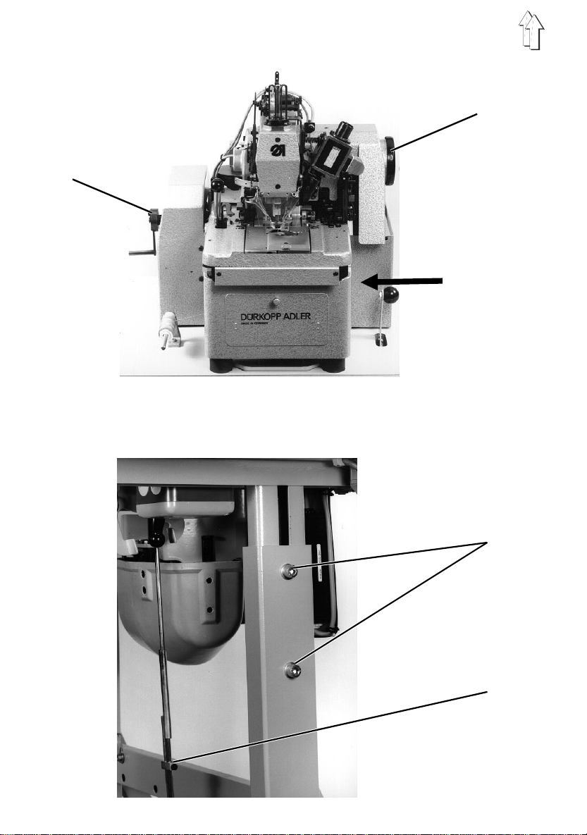
Prior to installation the following work must be conducted:
–
Remove the transport fastening screw 3 !
The screw is marked re d.
–
The needle bar is turned into its low position for transport.
By turning the handwheel 1 in the direction of the arrow bring the needle bar into
the high posi tion !
–
Push on crank ha ndle 2 and lock in place !
2.1 Transport
For in-house transport the machine must be lifted and transported on a suitable wagon
(e.g. pallet truck).
2.2 Work Heigh t
The work height i s adjustable between 76 and 104 cm.
The machine was set at a work height of 82 cm at the factory.
–
Loosen screws 4.
–
Set the machine horizontally at the desired work height.
–
Tighten screws 4.
2.3 Shift Linkage
The shift linkage from the hand shift lever to the pedal is to be set appropriate to the
work height.
–
Loosen screw 5.
–
Set the pedal.
The operator mus t be able to switch off the machi ne unhindered by stepping
forward on the pedal .
–
Tighten screw 5.
5

1
2
6

2.4 Y arn Unreeler for Yarn and W ool Cones
Optional equipment Article no. 558 3001
The yarn unreeler 1 is fastened to the middle traverse.
Additionally, the yarn unreeler can be equipped with a drawer.
This could be necessary, for example, when a small table is used and there is thus no
room available under the t able.
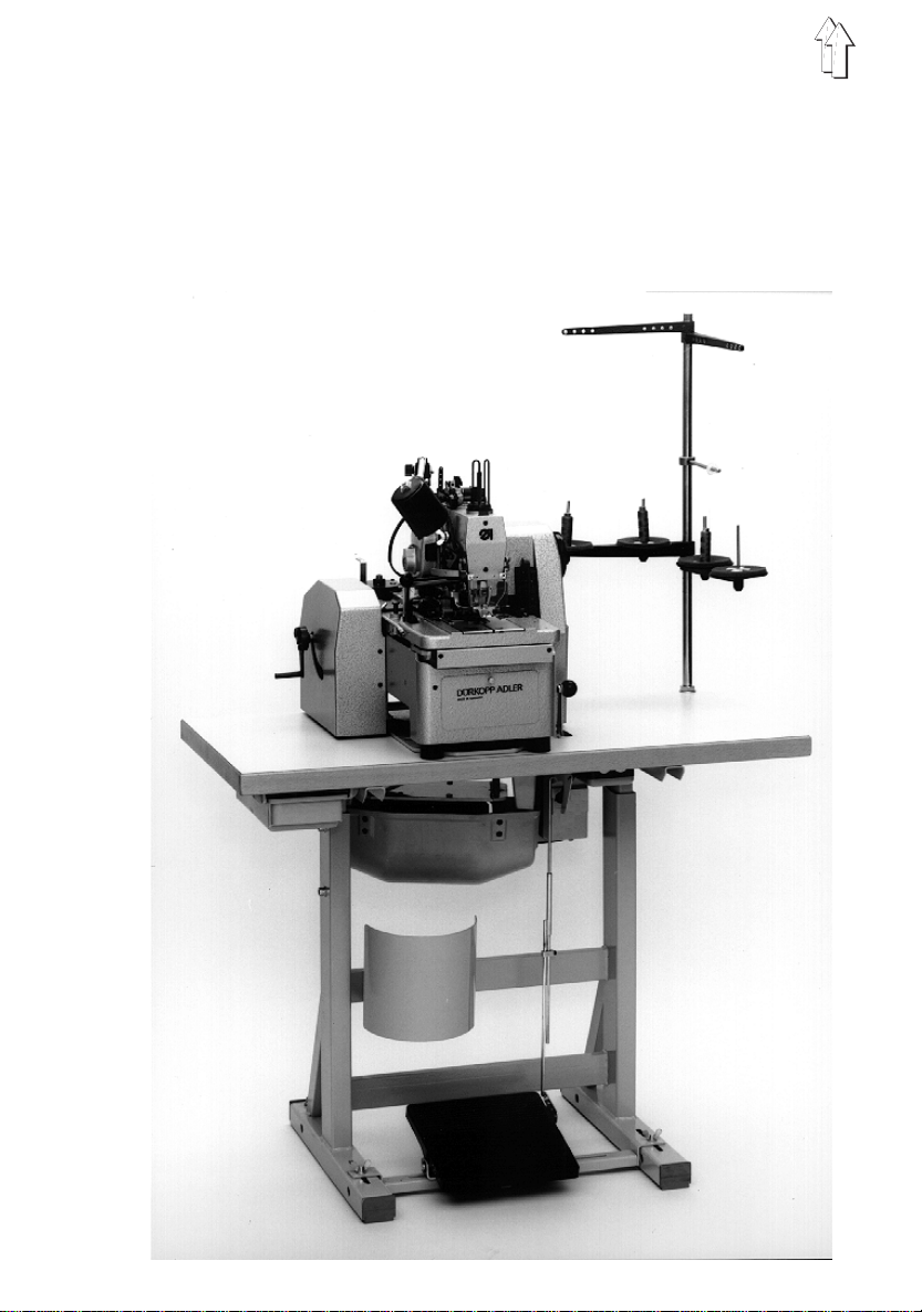
2.5 Y arn Stand
The mounting and position of the yarn stand can be seen in the illustration alongside.
–
Inser t stand 2 and fasten as shown in the picture w i th the nuts and washers.
–
Fasten the yarn roll holder and take-off arms.
The yarn roll hol der and take-off arms must stand ver tically above one another.
7

1 2 3 4
" Star " " Delta "
L1
U
X
L2 L3
VW
YZ
L1
L2 L3
U
VW
X
YZ
8

3. Electrical Connection
ATTENTION !
All work on the el ectrical equipment of the buttonhole
machine may only be conducted by electricians or suitablly
instructed personnel.
The mains plug must be disconnected.
3.1 Nominal V oltage
The nominal voltage listed on the motor rating plate and the mains voltage must be the
same !
3.2 Drive Package
For conversion to a differen t mains voltage the appropriate drive package must be
mounted.
The drive package consist s o f:
Motor 2, belt pulleys 1 + 4, V -belt and switch.
Order no.: Nominal voltage:
- 2410591 3 ~ 400 V + N, 50 Hz
- 2410575 3 ~ 230 V, 60 Hz
- 2295482 3 ~ 230 V, 50 Hz
- 2410540 1 ~ 230 V, 50 Hz
- 2410478 1 ~ 230 V, 60 Hz
For conversion to a differen t mains voltage the followi ng changes are to b e made:
–
If changed from 3-phase to 2-phase or vice versa, the whole drive package must
be changed.
–
If changed from 50 Hz to 60 Hz or vi ce versa, only the belt pul l ey an d t h e V-belt
must be replaced.
–
If changed fr om 3 ~ 400 V to 3 ~ 230 V or vice versa, the bri dges in the motor
terminal box 3 must be switched in
voltage !
The wiring is shown in the hook-up di agram.
" Star "
or
" Delta ",
appropriate to the mains
9

3.3 Checking the Direction of Motor Turn
ATTENTION !
Before commissio ning the buttonhole machine it is
essential that the direction of motor turn be checked.
Turning on the machine with an incorrect direction of motor
turn can lead to damage of unit.
1
With single phase, alternating current motors the direction of turn is set automatically if
termina l connections are m ade according to t he hook-up diagram.
With 3-phase m otors the directi on of turn must be checked.
–
The correct direction of turn i s shown be the arrow on the high-speed wheel 1.
–
If the direction of turn is incorrect, then a check must be must if the voltage supply
generates a clockwise rotary field.
If this is the case, then 2 phases in the connecting plug must be interchanged .
10

3.4 V -belt Tension
Setting V -belt tension left:
–
Loosen screw 2.
–
Turn the nuts 4 back so far that they do not lie onto the motor support plate.
The motor’s own weight sets the correct tension for the left V-belt (at the right in the
picture).
–
Tighten screw 2 again.
1
2
3
4
Setting V -belt tension right:
–
Turn the nuts 4 back so far that they do not lie onto the motor support plate.
The weight of the motor is now held by the V-belt.
–
Set the pressure spring 3 with the nuts 1 so that there is a clearance of 58 mm
between the nut s and the plate.
–
Screw the nuts 4 until they touch and then tighten one more turn.
This raises the support plate and slightly relieves the V-belt.
11

1
12
2
3

4. Installation of a Sewing Light
The sewing light is available as optional equipment.
Order no.: Article:
App. 1062 Halogen sewing light
App. 1541 Attachment kit
798 500088 Sewing light transformer
ATTENTION !
Pull the mains plug !
The electrica l connection may only be made by electricians
or appropri ately instructed personnel.
–
Attach the sewing light 1 as shown in the picture alongside.
–
Lay the sewing light wiring on the housing and guide through the table top opening.
–
Attach the sewing light transformer 2 under the table top.
–
Fasten the wiring lead to the sewing light. Connect the socket 3 and plug.
–
Lay the 220 V wiri ng lead (2 strand) between the switch and the sewing l i ght
transformer (see hook-up diagram).
13

5. Filling the Oil Reservoir
12
ATTENTION !
Before commissioning the machine the oil reservoirs 1 and
2 must be filled to the " max. " marking.
The lubrication of the buttonhol e m achine occur out of 2 reservoirs via an oil wick
system.
Additionally, the marked areas on the material carrier plate and the guide curve housing
must be oiled ( se e Operating Instru ctions 558).
As lubricating oil
The lubricating oil is available at
For the first filling there is an oil pillow in the accessories pack. The filling to be
conducted with the enclosed oil can.
ESSO SP-NK 10
or an equivalent oil is to be used.
DÜRKOPP-ADLER AG
business offices.
14
 Loading...