

Page 1

Contents: Page:
Part 4: Programming Instructions Class 550-16-23
Program Version: A 03
1. General .................................................. 3
2 Operating Elements of the Keypad (Control Panel) ....................... 4
3 Types of Operation
3.1 Normal Operation ............................................. 5
3.1.1 Setting the Fullness Value ........................................ 5
3.1.2 Turning the Supplementary Thread Tension On/Off ......................... 5
3.1.3 Turning the Thread Tension Off/On................................... 5
3.1.4 Bartack Inversion ............................................. 6
3.2 Automatic Operation ........................................... 7
3.3 Program Selection............................................. 7
3.3.1 Direct Program Selection ........................................ 7
3.3.2 Program Selection via Menu....................................... 8
3.3.3 Side Selection in a Program ....................................... 8
3.4 Program Variants ............................................. 9
4. Programmable Functions
4.1 Generating a New Program ....................................... 10
4.2 Temporary Alterations in a Step..................................... 11
4.3 Alterations in the Program ........................................ 11
4.4 Deleting a Program ............................................ 11
5. Parameter Settings
5.1 Machine Basic Settings.......................................... 12
5.1.1 Parameter List ............................................... 12
5.1.2 Base Stitch Length ............................................ 13
5.1.3 Needle Position at Drive Stop ...................................... 14
5.1.4 Foot Position at Drive Stop ....................................... 13
5.1.5 Foot Position after Thread Trimming.................................. 14
5.1.6 Beginning Bartack Type ......................................... 14
5.1.7 End Bartack Type ............................................. 14
5.1.8 Number of Bartack Stitches ....................................... 15
5.1.8 Bartack Speed ............................................... 15
5.1.10 Softstart................................................... 15
5.1.11 Number of Softstart Stitches....................................... 16
5.1.12 Softstart Speed .............................................. 16
5.1.13 Brightness Adjustment - Keypad .................................... 16
5.1.14 Left Pedal Setting ............................................. 17
5.2 Software Reset .............................................. 17
4
Page 2

Contents: Page:
6. Testing Programs
6.1 Display of the Machine Class and the Software Date ........................ 18
6.2 Display of Input Change ......................................... 19
6.3 Switching of Individual Outputs ..................................... 19
6.4 Checking the Sewing Drive ....................................... 20
6.5 Testing the Step Motors ......................................... 22
6.6 Testing the Flash ............................................. 23
6.7 Testing the RAM .............................................. 23
6.8 Readout of the Error Memory ...................................... 24
6.9 Testing the A/D Converter ........................................ 24
6.10 Testing the Keypad ............................................ 24
7. Setting Programs of the Machine
7.1 Correction Value/ Fullness Value Pedal ................................ 25
8. Indicators and Error Messages
8.1 Display Indicator.............................................. 26
8.2 Error Messages .............................................. 26
Annex ........................................................ 27
A.1 In- and Outputs .............................................. 27
2
Page 3

1. General
These programming instructions contain important information to the
safe, proper and economical use of the new generation of “DAC”
controls (Dürkopp Adler Control).
Ease of Programming
The user can program 99 freely-programmable programs with up to 13
steps for the left and right piece.
–
Supplementary thread tension as of a specific fullness value.
–
31 fullness values can be selected.
–
Loading of all original parameters (Reset)
–
All base parameters can be set via the keypad.
–
Comprehensive model programming.
–
The sewing drive is controlled directly through the pedal.
Setting and Testing Programs
The DAC includes the integrated comprehensive
MULTITEST testing and monitoring system.
A microcomputer assumes the control tasks, monitors the sewing
process and signals operating faults and malfunctions.
Errors and test results are shown in a LCD display. Under normal
working conditions the display shows information to operation and the
sewing process.
When an operating error or a malfunction occurs the functions are
interrupted.
In some cases the main switch must be turned off during error
correction for safety reasons.
A portion of the error messages is meant only for the service
personnel.
Special programs facilitate mechanical adjustments and make possible
a rapid testing of the input and output elements without additional
measuring apparatus.
4
3
Page 4
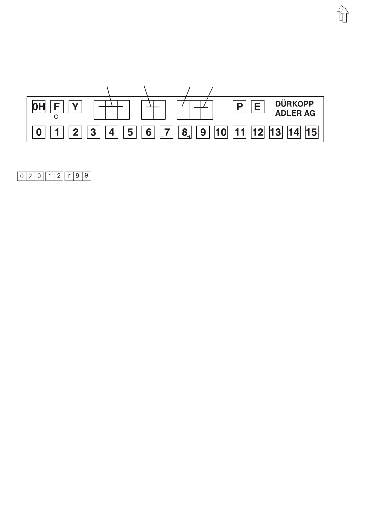
2. Operating Elements of the Keypad (Control Panel)
The entry and indicating of data occurs via a keypad with an 8-digit
display which is divided into 3 blocks.
Fullness value Step Sleeve side Program number
Display
During the normal program run the display is built up as follows :
Left 3 digits : Display of the fullness value
Middle 2 digits : Step display
Right 3 digits : Display of the piece (right or left) and display of the
program number
When a testing program (or similar) is activated, a number of other
parameters are shown in the display.
Key/Key Groups Function
0H Reverse bartack - manual
F Supplementary thread tension on/off
(the active function is designated by the green LED)
F+0 Needle high/low
F+1 Needle thread tension on/off
F+2 Bartack inversion
Y+F Global parameters
Y+P Programming mode on/off (Teach-In)
Y + P+E Program deletion
E Alternation-piece left/ piece right
0 to 15 Setting fullness values
4
Page 5

3. Types of Operation
3.1 Normal Operation (without Programming)
With the following key sequence, the direct operation is switched on.
–
Press the “P” key.
The display shows:
–
Press “0” and “0”
Program 00 is called up.
The display shows:
3.1.1 Setting the Fullness Value
The desired fullness value is entered with the “1”to“15” keys. An
intermediate value (1/2) is set by pressing neighbouring fullness value
keys simultaneously or via the left pedal.
Depending on the setting (Parameter-Supplementary pedal), a setting
via the keys is not possible.
Setting a fullness value: (Example: Fullness value 5)
–
Press the “5” key.
The display shows:
3.1.2 Turning the Supplementary Thread Tension On/Off
The supplementary thread tension can be turned on at any time.
–
Press the “F” key.
The supplementary tension is turned on.
The green LED under the key is lit.
–
Press the “F” key again.
The supplementary tension is turned off.
The green LED goes out.
3.1.3 Turning the Thread Tension Off/On
By simultaneously pressing the “F” and “1” keys, the thread tension
can be turned off and on again.
–
Hold down the “F” key and tap the “1” key.
The thread tension is turned off.
–
Hold down the “F” key and tap the “1” key.
The thread tension is turned on.
4
5
Page 6

3.1.4 Bartack Inversion
The bartack set in the parameters (see Chapter 1.7 Parameter
Settings) is inverted (suppressed) by simultaneously pressing the “F”
and “2” keys.
Seam beginning:
–
Hold down the “F” key and tap the “2” key.
The bartack is not sewn.
Seam end:
–
Hold down the “F” key and tap the “2” key.
The bartack is not sewn.
6
Page 7

3.2 Automatic Operation
3.3 Program Selection
3.3.1 Direct Program Selection
In automatic operation the step and program number displays show the
selected program and the current step.
The automatic operation is divided into the functions :
–
Automatic run
–
Programming operation for generating a new program
–
Editing operation for changing of given programs
Up to 99 programs are possible.
Additionally, the selected piece (left or right sleeve) is shown in the
program number display. At the end of the program the display blinks.
If the program number is known, it can be entered directly.
Order of operations
–
Press the “P” key.
The display shows:
–
Enter the program number. (Example 17)
The numeric entry occurs with the 0 to 9 keys. After the entry of the
second number, the entry is automatically concluded.
If the program exists in the memory, the following appears in the
display for example :
–
After a program is activated, the step 01 is set.
The program is immediately ready for operation.
The “Automatic” mode is activated.
–
If the program is not in the memory, the left display blinks. By
holding down the “Y” key and tapping the “P” key, the entry of a
new program can now begin or the program search be repeated by
pressing the “P” key.
4
7
Page 8

3.3.2 Program Selection via Menu
If the desired program number is not known, all programs can be run
through in the following manner.
Order of operations
–
Press the “P” key.
Change-over to the “Program Selection” mode.
–
Press the “Y” key.
The first program is shown.
Each pressing of the “Y” key moves to and shows the next
program.
If the program has valid data assigned to it, the following display
appears:
If the program has no valid data assigned to it, the following
appears:
–
If the displayed program is to be selected,
press the “E” key. (Example program 01)
The following display appears.
3.3.3 Side Selection in a Program
After selection of a program one always goes first to the right piece (if
a right sleeve has been programmed).
In the automatic mode can one, however, alternate between “right” and
“left” sleeve at any time, if the sewing cycle has not yet begun and a
program with right and left sleeve was selected.
–
Press the “E” key.
The controls switch to the left piece.
The display shows:
–
Press the “E” key again.
The controls switch to the right piece again.
The display shows:
8
Page 9

3.4 Program Variants
For the adaption to differing types of material with the same model cut,
the fullness values can be changed via the “0" to ”15" keys and via the
supplementary foot pedal by + 0.5 and - 0.5.
The changes apply only for the step selected at the moment and are
deleted at the next step selection.
Increase the fullness value by + 0.5
Example: Set fullness value = 8
–
Step the left foot pedal forward.
The fullness value is increased by 0.5.
Decrease the fullness value by - 0.5
Example: Set fullness value = 8
–
Step the left foot pedal to the back.
The fullness value is decreased by 0.5.
4
9
Page 10

4. Programmable Functions
The machine settings described in the following are saved in memory
with each program.
4.1 Generating a New Program
The generation of a new program starts with the entry of a non-existent
program number.
–
Press the “P” key.
–
Enter the 2-digit program number (Example program 17).
The left display blinks.
(If the left display does not blink, the selected program already
exists.)
–
Hold down the “Y” key and tap the “P” key.
“01" appears in the center display.
The dots in the ”Step" display and the “Sleeve Side” display blink.
Note:
One can alternate between left and right piece with the “E” key until the
first fullness value/ special function has been selected (the sleeve side
display no longer blinks).
–
Enter the fullness value by pressing one of the 0 to 15 keys.
Activate possible additional functions for the step by pressing one
of the following keys :
- F : Supplementary thread tension on / off
- F+1: Needle thread tension on / off
–
Press the knee switch.
The next step is selected.
The entry value is saved.
The next value can be entered.
–
This programming order can be continued up to step 13.
–
Press the “E” key.
The established values are mirrored for the second piece and
saved to memory.
or
–
Press the “Y”+"P“ key.
The established values are saved only for the current piece and
not mirrored.
Note:
During teaching, one can go back one step at a time with the “Y” key.
10
Page 11

4.2 Temporary Alterations in a Step
Every function in a step can be changed as required. This alteration is
only valid for this program run. These alterations are lost if the step is
exited. Parameter alterations can also be made.
–
Press the key for the desired fullness value.
The new fullness value appears in the left display.
The original value is active again when the program is run next.
4.3 Alterations in the Program
If the program is to be permanently changed, proceed as follows :
–
Select the step to be changed.
–
Hold down the “Y” key and tap the “P” key.
The editing mode is switched on.
The decimal points in the display “Step” blink.
Example:
Enter the new fullness value.
–
Enter possible other parameters, such as e.g. additional thread
tension.
–
Hold down the “Y” key and tap the “P” key.
The complete program is stored.
The program is continued with the altered step.
or
–
Press the “E” key.
The program is mirrored to the other sleeve side.
4
4.4 Deleting a Program
If an active program is to be deleted, this is possible with the following
key entries :
–
Hold down the “Y” key and type the “P” and “E”keys.
The keys must be held down for 2 seconds, then the program
number disappears.
The program number entry appears.
–
The program number blinks.
A new program number can be entered.
Note:
The deleting of a program is only possible in a program which has not
been started.
11
Page 12

5. Parameter Settings
5.1 Machine Basic Settings
5.1.1 Parameter List
The base settings may only be made when the sewing drive is idle.
They apply to all types of operation.
Order of operations
–
Hold down the “Y” key and tap the “F” key.
The parameter menu is turned on.
–
Briefly operate the “Y” key.
This advances the parameters one at a time
–
Hold down the “Y” key and tap the “F” key.
The parameter menu is turned off.
No. Name Value Range Value
1 Base sewing length 1.5 - 5.5 mm 2.5 mm
2 Needle position 0 = down Down
1=up
3 Foot position-seam 0 = down Down
1=up
4 Foot position-TT 0 = down Down
1=up
5 Beginning bartack type 0 = off Off
1 = simple
2 = double
6 End bartack type 0 = off Off
1 = simple
2 = double
7 Designated number of 1 - 9 5
bartack stitches
8 Designated bartack 500- 2000 1000
speed
9 Softstart on/off On
10 Number of softstart 1 - 20 2
stitches
11 Softstart speed 200 - 1800 1000
12 Display brightness 0 - 15 8
13 Analog pedal 0 = +/- 0,5 0
1=0-15
2=0-7,5
3=7,5-15
12
Page 13

5.1.2 Base Stitch Length
5.1.3 Needle Position at Drive Stop
This parameter sets the base stitch length. Values between 1.5 and 5.5
can be set (steps of 0.1 mm)
Order of operations
–
Hold down the “Y” key and tap the “F” key.
The parameter menu is turned on.
Advance to the desired parameter by repeated pressing of the “Y”
key.
–
Press the appropriate key for the desired stitch length.
(Example 1,5 mm base stitch length)
Press the “1" key and the ”5"key.
With this parameter the position in which the needle stops when the
drive stops is set.
5.1.4 Foot Position at Drive Stop
Order of operations
–
Hold down the “Y” key and tap the “F” key.
The parameter menu is turned on.
–
Advance to the desired parameter by repeated pressing of the “Y”
key.
–
Press the appropriate key for the desired needle position.
Key 1 :Position down
Key 2 :Position up
After the setting of the parameter, the machine must be turned off and
on again in order for the value to be applied.
This parameter sets the position in which the sewing foot stops when
the drive is stopped.
Order of operations
–
Hold down the “Y” key and tap the “F” key.
The parameter menu is turned on.
–
Advance to the desired parameter by repeated pressing of the “Y”
key.
Press the appropriate key for the desired sewing foot position:
Key 1 : Position down
Key 2 : Position up
4
13
Page 14

5.1.5 Foot Position after Thread Trimming
This parameter sets the position in which the sewing foot stops after
the thread trimming.
Order of operations
–
Hold down the “Y” key and tap the “F” key.
The parameter menu is turned on.
–
Advance to the desired parameter by repeated pressing of the “Y”
key.
Press the appropriate key for the desired sewing foot position :
Key 1 : Position down
Key 2 : Position up
5.1.6 Beginning Bartack Type
This parameter determines whether the beginning bartack is to be
conducted as a single or a double bartack.
Order of operations
–
Hold down the “Y” key and tap the “F” key.
The parameter menu is turned on.
–
Advance to the desired parameter by repeated pressing of the “Y”
key.
Press the appropriate key:
Key 0: Bartack off
Key 1 : Single bartack
Key 2 : Double bartack
5.1.7 End Bartack Type
This parameter determines whether the end bartack is to be conducted
as a single or a double bartack.
Order of operations
–
Hold down the “Y” key and tap the “F” key.
The parameter menu is turned on.
–
Advance to the desired parameter by repeated pressing of the “Y”
key.
Press the appropriate key:
Key 0 : Bartack off
Key 1 : Single bartack
Key 2 : Double bartack
14
Page 15

5.1.8 Number of Bartack Stitches
5.1.9 Bartack Speed
This parameter sets the number of bartack stitches.
Order of operations
–
Hold down the “Y” key and tap the “F” key.
The parameter menu is turned on.
–
Advance to the desired parameter by repeated pressing of the “Y”
key.
Press the appropriate key for the desired number of stitches :
Key1:1Stitch
Key2:2Stitches
Key3:3Stitches
....
Key9:9Stitches
This parameter sets the bartack speed.
5.1.10 Softstart
Order of operations
–
Hold down the “Y” key and tap the “F” key.
The parameter menu is turned on.
–
Advance to the desired parameter by repeated pressing of the “Y”
key.
Press the appropriate key for the desired bartack speed :
Step 100 rpm.
The display of the speed limitation is to be multiplied by a factor of 10.
Key 8 : Plus
Key 7 : Minus
This parameters turns the softstart on or off.
Order of operations
–
Hold down the “Y” key and tap the “F” key.
The parameter menu is turned on.
–
Advance to the desired parameter by repeated pressing of the “Y”
key.
Press the appropriate key :
4
Key 0: OFF
Key 1: ON
15
Page 16

5.1.11 Number of Softstart Stitches
5.1.12 Softstart Speed
This parameter sets the number of stitches which are to be sewn at the
lower speed.
Order of operations
–
Hold down the “Y” key and tap the “F” key.
The parameter menu is turned on.
–
By repeatedly pressing the “Y” key advance to the desired
parameter.
Press the appropriate key for the desired number of stitches:
Value range: 1 to 20.
Key 8: Plus
Key 7: Minus
This parameter sets the softstart speed.
Order of operations
–
Hold down the “Y” key and tap the “F” key.
The parameter menu is turned on.
Advance to the desired parameter by repeated pressing of the “Y”
key.
Press the appropriate key for the desired softstart speed :
Step 100 rpm.
The display of the speed limitation is to be multiplied by a factor of 10.
Key 8: Plus
Key 7: Minus
5.1.13 Brightness Adjustment - Keypad
This parameter sets the brightness of the keypad.
Order of operations
–
Hold down the “Y” key and tap the “F” key.
The parameter menu is turned on.
–
Advance to the desired parameter by repeated pressing of the “Y”
key.
Key 8 : Brighter
Key 7 : Darker
16
Page 17

5.1.14 Left Pedal Setting
5.2 Software Reset
This parameter sets the type of function of the supplementary pedal.
Order of operations
–
Hold down the “Y” key and tap the “F” key.
The parameter menu is turned on.
–
Advance to the desired parameter by repeated pressing of the “Y”
key.
Key 0 : Correction value pedal in the manual mode
Key 1 : 30-step pedal
(Fullness values from 0-15 in the manual mode)
Key 2 : 15- step pedal
(Fullness values from 0-7.0 in the manual mode)
Key 3 : 15- step pedal
(Fullness values from 7.5-15 in the manual mode)
It is possible through the Software Reset to restore all the machine
parameters to the original factory setting.
–
Switch off the machine.
–
Hold down the “F” and “6” keys and switch the machine on again.
4
17
Page 18

6. Testing Programs
If the “F”+“1” keys are held pressed when the machine is turned on,
the test mode is activated.
The following testing programs can be selected :
1. Display of the machine class and software version
2. Display of input change
3. Switching of individual outputs
4. Checking the sewing motor
5. Testing the step motors
6. Testing the flash
7. Testing the RAM
8. Read-out of the error memory
9. Testing the A/D converter
10. Testing the keypad
Order of operations
–
When turning on the sewing machine, hold the “F” and “1” keys
down.
The test mode is activated.
The following display appears:
–
Release the “F”+“1”key.
The first test display appears.
–
With each pressing of the “+” and “-” keys there is an advance to
the next testing program.
After the tenth testing program the first test program appears
again.
–
The testing program is ended by turning the machine off and on.
–
Press the “E” key.
The testing program is activated.
6.1 Display of the Machine Class and the Software Date
Entries cannot be made in this testing program. It only shows the
machine class and the software version.
Order of operations
–
Turn on the test mode (see Chapter 1.5).
–
Press the “E” key.
The display of the machine class appears.
–
Press the “E” key.
The display of the software version appears.
18
–
Press the “E” key.
The display of the date of the software appears.
Example: 10.01.2000
Page 19

6.2 Display of Input Change
In this testing program the complete input structure is monitored for
changes. If a change occurred, the input number and the switching
status are displayed.
Order of operations
–
Turn on the test mode.
–
Advance to the desired program by pressing the “+” and “-” keys.
–
Strike the “E” key.
The following display appears:
–
Enter an input manually.
For example:
The input 7 (knee lever) has changed to status “OFF”.
Inputs see Annex A..1.
Input 7 = Knee lever
6.3 Switching of Individual Outputs
In this testing program all outputs can be switched individually. The
change of a switch is shown in the display.
Order of operations
–
Turn on the test mode (see Chapter 6).
–
Advance to the desired program by repeated pressing the “+” and “-” keys.
–
Strike the “E” key.
The program is turned on.
–
Strike the “Y” key.
The switching status of the selected output will be checked.
–
Use the “+” and the “-” keys to switch to the next output.
–
Strike the “Y” key.
The switching status of the selected output will be checked.
For example:
The output 5 has changed to status “ON”.
4
Outputs see Annex A.1.
Output 1 = Reserve
Output 2 = Supplementary thread tension
Output 3 = Main thread tension
Output 4 = Sewing foot lift
Output 5 = Thread cutter
19
Page 20
6.4 Checking the Sewing Drive
The sewing drive can be checked with this test.
Order of operations
–
–
–
If an error is found during initialization, this will be reported. The
number corresponds to the error byte of the Efka drive.
The software status can be called up by pressing the “E” key if you get
an OK message.
–
Turn on the test mode (see Chapter 6).
Advance to the desired program by repeatedly pressing of the “+”or“-”
keys.
Press the “E” key.
The sewing drive is initialized and run into the zero position.
The display shows:
Press the “E” key.
The first part of the software status is displayed.
Display: Software status 1:
–
Press the “E” key.
The second part of the software status is displayed.
Display: Software status 2:
–
Press the “E” key.
The third part of the software status is displayed.
Display: Software status 3:
Additionally, the date code of the software version is displayed.
–
Press the “E” key.
Display Date Part 1:
–
Press the “E” key.
Display Date Part 2:
–
Press the “E” key.
Display Date Part 3:
20
–
Press the “E” key.
Display Date Part 4:
Page 21

With subprogram 9 the sewing motor can be turned on. The motor will
only start running after an increase of the speed to 200 rpm.
The display of the speed must be multiplied by a factor of 10 in order to
establish the set value.
–
Press the “E” key.
Subprogram 9 is selected.
–
Press the “+” key.
The speed of the motor must be set to 200 rpm for it to start
running.
–
Press the “E” key.
The sewing motor is stopped and the subprogram ended.
Error message
If an error occurs during the sewing drive check, the following will
display:
–
Check the Efka drive, controller, electrical connections.
–
Eventually change the controller.
–
Screw off the cover of the switch cabinet.
4
21
Page 22
6.5 Testing the Step Motors
The step motors are checked with this test.
ATTENTION !
Any work on the electrical equipment of the machine should be carried
out exclusively by the properly qualified electricians or by the properly
qualified staff.
Order of operations
–
Turn on the test mode (see Chapter 6).
–
Advance to the desired program by repeated pressing of the “+”
and “-” keys.
–
Press the “E” key.
The status of the step motor high-power levels is checked.
Error message:
The LED indicators of the step motor high-power levels in the
switch cabinet must be checked.
–
Hold down the “Y” key.
The step motors are moved.
–
Press the “E” key.
The test ends.
22
Page 23
6.6 Testing the Flash
The flash memory is checked with this test.
Order of operations
–
Turn on the test mode (see Chapter 6).
–
Advance to the desired program by repeated pressing of the “+”
and “-” keys.
–
Press the “E” key and hold it down until the display appears.
The flash is checked.
The display appears:
OK message:
Error message:
Leaving the program
–
Turn the main switch off and turn it on again.
6.7 Testing the RAM
The RAM memory is checked with this test.
Order of operations
–
Turn on the test mode (see Chapter 6).
–
Advance to the desired program by repeated pressing of the “+”
and “-” keys.
–
Press the “E” key and hold it down until the display appears.
The RAM is checked.
The display appears:
OK message:
Error message:
Leaving the program
–
Turn the main switch off and turn it on again.
4
23
Page 24

6.8 Readout of the Error Memory
This test provides a readout of the last 10 errors occurring.
Order of operations
–
Turn on the test mode (see Chapter 1.5).
–
Advance to the desired program by repeated pressing of the “+”
and “-”keys.
–
Press the “E” key.
The first error is shown.
–
Press the “+” key.
The second error is shown.
–
..............
–
Press the “+” key.
The tenth error is shown.
–
If no errors are present, this display appears:
–
Press the “Y”+“P”+“E”keys.
The error memory is cleared.
6.9 Testing the A/D Converter
The positions of the supplementary pedal are checked with this test.
Dependent on the position of the pedal, the value measured by the
controls is displayed. Example: 4.01 V.
Order of operations
–
–
–
–
–
6.10 Testing the Keypad
Turn on the test mode (see Chapter 6).
Advance to the desired program by repeated pressing of the “Y”
key.
Press the “E” key.
The current voltage value is displayed.
Operate the left foot pedal.
The voltage value must change.
Press the “E” key.
The testing program is exited.
24
The individual keys can be checked with this test.
They are displayed on the keypad.
–
Press the “E” key.
The testing program is exited.
Page 25

7. Setting Programs of the Machine
7.1 Correction Value/ Fullness Value Pedal
The supplementary pedal is set with this program.
Order of operations
–
Hold down the “F” and “2” keys when turning on the machine.
–
Step the foot pedal completely forward,
keep it in this position and operate the knee switch.
The first measured value is established.
–
Bring the foot pedal back into the zero position.
–
Operate the knee switch.
The second measured value is established.
–
Step all the way back on the foot pedal,
keep it in this position and operate the knee switch.
The measured values are checked for reasonableness.
If the values are all right, the correction value is calculated
automatically.
This display appears:
If the values are not reasonable, this display appears:
–
Turn the machine off and on again.
When receiving an error message proceed as follows:
–
Press the “E” key.
–
Enter the positions of the foot pedal again (see above).
If necessary, conduct Test 6.9 (Testing the A/D Converter).
4
25
Page 26

8. Indicators and Error Messages
8.1 Display Indicator
During the bootphase of the controls (after switching on the machine) a
display test is shown first, during which all illuminated elements of the
display are triggered once.
Then the controls switch to the operational mode which was active
before the machine was turned off.
8.2 Error Messages
Name Number
Sewing motor error 135 to 145
NV_RAM checksum error 183
CPU error 300
If an error occurs during sewing, this can be remedied by turning the
main switch off and on again.
26
Page 27

Annex
A.1 In- and Outputs
Input Designation
7 Knee switch
Output Designation
1 Reserve
2 Supplementary thread tension
3 Main thread tension
4 Sewing foot lift
5 Thread trimmer
4
27
Page 28

Notes:
28
 Loading...