

Page 1

Contents Page:
Home
Part 4: Programming manual Cl. 550-12-12
1. General
2. Operating elements
2.1 On-screen displays . . . . . . . . . . . . . . . . . . . . . . . . . . . . . . . . . . . . . . . . . 4
2.2 Screen operating elements . . . . . . . . . . . . . . . . . . . . . . . . . . . . . . . . . . . . . 5
2.3 Keyboard operating elements . . . . . . . . . . . . . . . . . . . . . . . . . . . . . . . . . . . . 6, 7
3. Size tables
3.1 Sizes for 200-3 . . . . . . . . . . . . . . . . . . . . . . . . . . . . . . . . . . . . . . . . . . . . 8
3.2 Sizes for 200-6 . . . . . . . . . . . . . . . . . . . . . . . . . . . . . . . . . . . . . . . . . . . . 9, 10
4. Base setting of the controls
4.1 200-3 controls . . . . . . . . . . . . . . . . . . . . . . . . . . . . . . . . . . . . . . . . . . . . 11
4.2 200-6 controls . . . . . . . . . . . . . . . . . . . . . . . . . . . . . . . . . . . . . . . . . . . . 12
4.3 Selecting the base size per program . . . . . . . . . . . . . . . . . . . . . . . . . . . . . . . . 13
4.4 Allocation of the function keys . . . . . . . . . . . . . . . . . . . . . . . . . . . . . . . . . . . 14
5. Reset
6. Programming instructions:
6.1 Pre-gathering the sleeve head/setting the sleeve . . . . . . . . . . . . . . . . . . . . . . . . . 15- 17
6.2 Reinforcing . . . . . . . . . . . . . . . . . . . . . . . . . . . . . . . . . . . . . . . . . . . . . . 18-21
. . . . . . . . . . . . . . . . . . . . . . . . . . . . . . . . . . . . . . . . . . . . . . . . 3
. . . . . . . . . . . . . . . . . . . . . . . . . . . . . . . . . . . . . . . . . . . . . . . . . 14
7. Changing an existing program
7.1 Changing the entire set of sizes . . . . . . . . . . . . . . . . . . . . . . . . . . . . . . . . . . 22
7.2 Changing only one size . . . . . . . . . . . . . . . . . . . . . . . . . . . . . . . . . . . . . . . 22
7.3 Changing only the right or left piece . . . . . . . . . . . . . . . . . . . . . . . . . . . . . . . . 23
7.4 Selecting and changing the half size . . . . . . . . . . . . . . . . . . . . . . . . . . . . . . . . 23
8. Program sequence
8.1 Setting up the program sequence . . . . . . . . . . . . . . . . . . . . . . . . . . . . . . . . . 24, 25
8.2 Activating the program sequence . . . . . . . . . . . . . . . . . . . . . . . . . . . . . . . . . . 25
8.3 Erasing the program sequence . . . . . . . . . . . . . . . . . . . . . . . . . . . . . . . . . . . 25
9. Memory card
9.1 Transferring programs to the memory card . . . . . . . . . . . . . . . . . . . . . . . . . . . . 26
9.2 Loading programs into the control . . . . . . . . . . . . . . . . . . . . . . . . . . . . . . . . . 27
10. Entering text
11. Calling up the EPROM states
11.1 Preselecting the application (DOB = ladies’ wear, HK = men’s and boys’ wear) . . . . . . . . 29
11.2 Replacing the EPROMs . . . . . . . . . . . . . . . . . . . . . . . . . . . . . . . . . . . . . . . 30
. . . . . . . . . . . . . . . . . . . . . . . . . . . . . . . . . . . . . . . . . . . . . 28
Page 2

12. Setting the starting position of the ellipse
. . . . . . . . . . . . . . . . . . . . . . . . . . 31
13. Changing the language of the on-screen
14. Adjusting the gathering values to different materials /
percental change of the crimp value
15. Determining the gathering value
16. Sizes
16.1 Correcting the monitor display (200-3 / 200-6) . . . . . . . . . . . . . . . . . . . . . . . . . . 34, 35
16.2 Replacing the battery of the memory card (200-3 / 200-6) . . . . . . . . . . . . . . . . . . . 35
16.3 Replacing the fuse (200-3 / 200-6) . . . . . . . . . . . . . . . . . . . . . . . . . . . . . . . . 36
16.4 Replacing the mains connection (200-3 / 200-6) . . . . . . . . . . . . . . . . . . . . . . . . . 37
16.5 Replacing the graphic card (200-3 / 200-6) . . . . . . . . . . . . . . . . . . . . . . . . . . . . 37
16.6 Replacing the battery (200-3 / 200-6) . . . . . . . . . . . . . . . . . . . . . . . . . . . . . . . 38
16.7 Replacing the EPROMs (200-3 / 200-6) . . . . . . . . . . . . . . . . . . . . . . . . . . . . . 38, 39
. . . . . . . . . . . . . . . . . . . . . . . . . . . . . . . . 33
text . . . . . . . . . . . . . . . . . . . . . . . . . 32
. . . . . . . . . . . . . . . . . . . . . . . . . . . . . . 33
Page 3
1. General
This programming manual contains important information on the safe,
proper and ec on om i c us e of th e 200-3 and 200-6 mu lt ip r og r am control.
200-3
Memory capacity of
the controls
Data transfer Transfer to a 32k memory card Transfer to a 128k memory card
Programming
comfort
20 different mode ls wi t h
10 size grou ps
The controls are marked with the appropriate identification plate. From this
memory card th e d ata can be read-i n t o a mu l ti p r og ram control again .
Transfers from a 128k card to a 32k card and vice versa are not possible.
This procedu r e ca n be repated as of te n a s de s ir ed wi t hi n th e s t orage period
of the memory c a r d.
Storage period of the memory card: Approx. 4 years without a battery
replacement.
The base size entered is valid for all
programs.
There are 10 programs in memory.
The sewing pr o gra m i s g en er a te d f or o ne sl ee v e i n th e b as e s i ze t hr o ug h a
teach-in procedure.
The program f or t he s ec o nd s l ee ve i s a r ri v ed at thr o ug h mi rr o ri ng . T he
transfer of t he ge ne r at ed pr o gra m i n th e c o mp l et e s i ze set is automa ti c.
The fullness controls allow a precisely repeatable setting and calling-up of
varying fullness quantities.
The automatic p r og ram s eq ue nc e as sures uniform qu al i t y an d h i gh capacity.
controls
200-6
15 different models with
15 size groups and with the
corresponding half sizes (see size
table).
A preprogramming is possible in al l
model variants.
The base size can be chosen for
each program.
The memory co ntains 45 addit i on al
sizes, that is, all normal half sizes,
too.
controls
Operating c o mf ort All steps n ecessary for the ge ne ration of a program are shown in a mo ni t or
text. The moni t or t ex t c an be c all e d u p i n di ffer e nt la ng ua ge s .
A graphic shows the in di v idual programmes s e wi n g steps.
All important data is listed on the monitor next to the graphic.
Programs can be given names and comments via text entry.
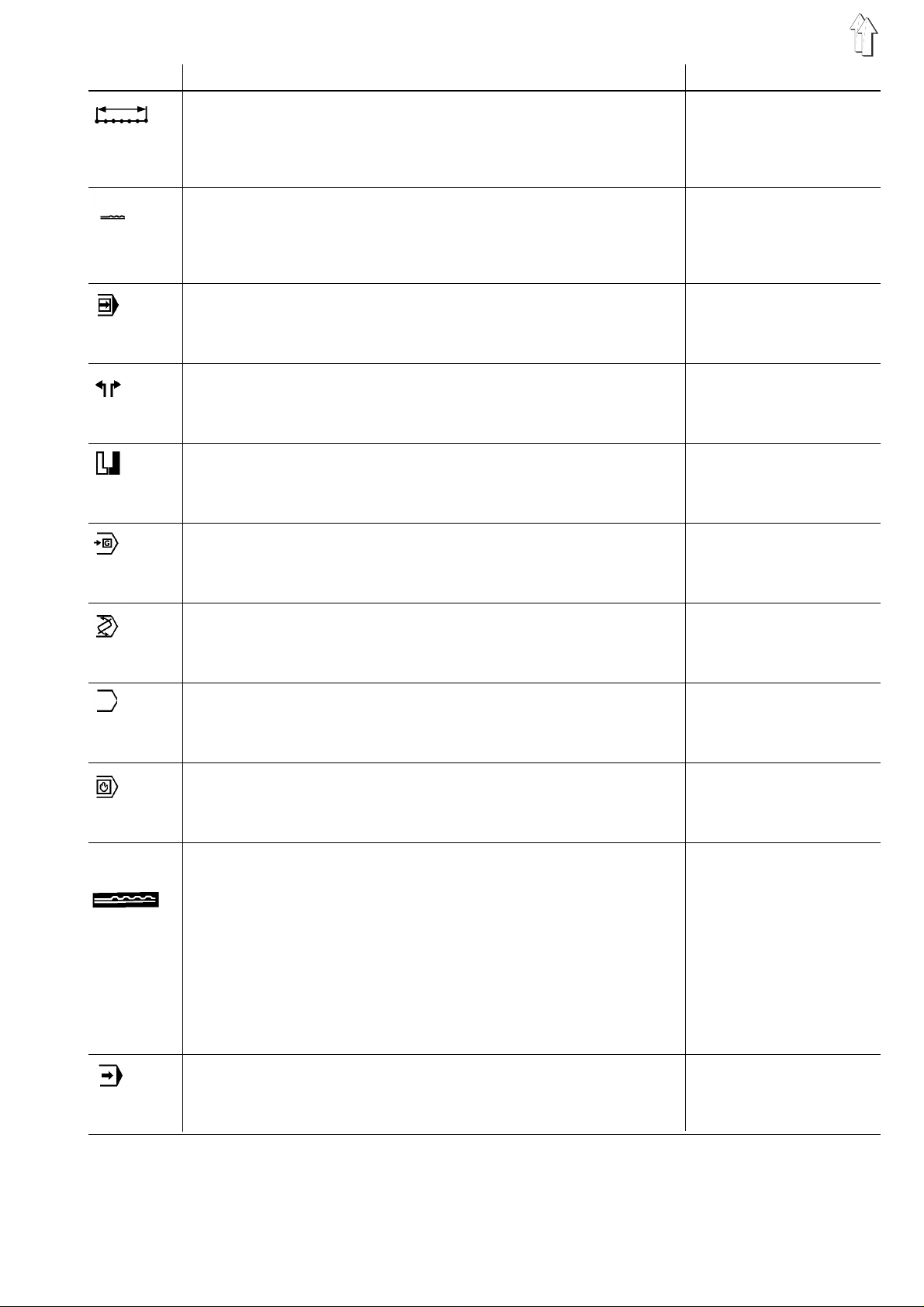
Please note
The symbols r e pre s en ti n g k e y s i n t hi s d oc u me nt at i on ar e gi ven in the
table below.
Symbol Signification
... + ...
(eg Y +
. ,
..
...
(eg P , 0)
Press the keys
P)
Press the key Y and keep depre s s ed ,
additionall y p res s t he k ey P.
Press the keys
Press the key P and release.
Then press the key 0.
at the same time
successive ly
.
.
3
Page 4
2. Operating elements
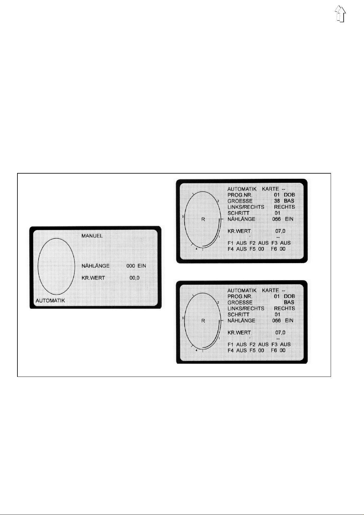
2.1 On-screen displ ays
On-screen displays
Each operation mode (manual operation and automatic operation) is
represente d b y a s p ec i a l on -s c ree n display.
Screen operating elements
The operating elements of the
control are divided up into two key group s.
screen operating elements
The
screen.
They consis t of fi v e k eys l o c at ed un de r ne at h e ac h ot he r.
Keyboard operating elements
keyboard operating elements
The
They consist of 30 k ey s a r ran ge d i n tw o ro ws .
200-3
are located on the left beside the
200-6
and
are located underneath the screen.
multiple program
Manual operation
Automatic operation 200-3 controls
038
Automatic operation 200-6 controls
Manual operation
With the manual operation the operator preselects the gathering value.
The number of s ti t c he s i s c ou nt ed au to ma ti c a l l y du r i ng s ew i ng an d
displayed on the screen.
Automatic operation
With the automatic operation the on-screen display contains all values
needed to set up a complete sewing program.
The operator ca n b r ea k up th e s e am s ection into a max i mu m o f 1 3
steps.
The programmed steps are mar k ed i n t he graphics.
4
Page 5
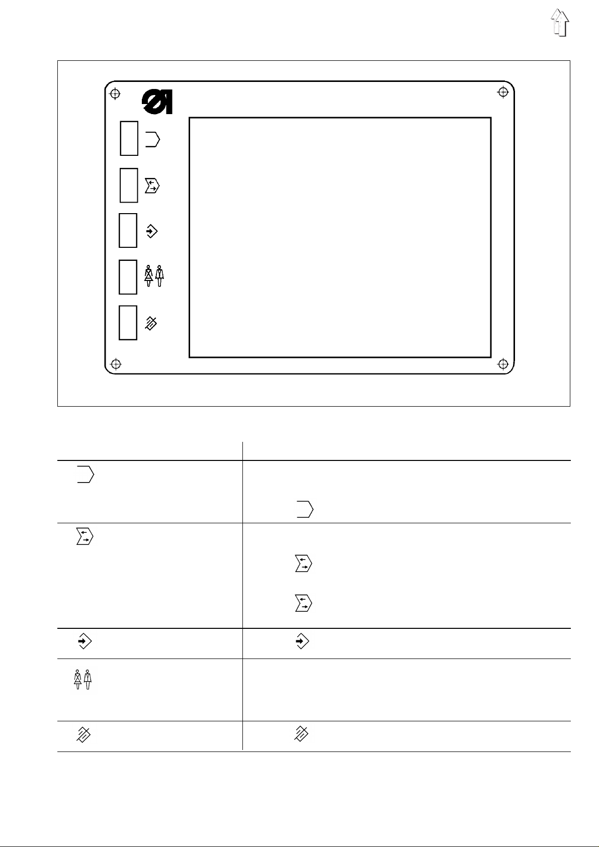
2.2 Screen operating elements
Key Function
Programming mode:
- Selecti ng th e g rap hi c s
- Enabling en d w i th /without thread tr immer (FA)
- Y + : calling up text input
Data transfer to memory card:
- Changing the direction of transfer
- Y + : transf erring data
Program sequence mode:
- Y + : calling up the program sequence mode
- Selecting the program sequence (A-E)
Y
+ : calling up the program sequence mode (press
both red k eys )
Changing the application (DOB/HK):
- First, press the key Y and the
Programming mode:
- Setting the basic size in the 1st step
Y
+ : erasin g the progr am
main switch
at the same time
5
Page 6
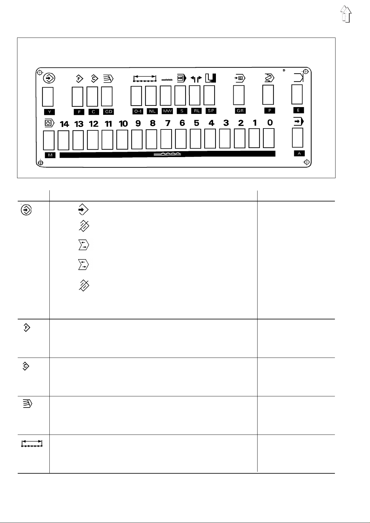
2.3 Keyboard operating elements
Key Function Display
Y
+ : calling up the programming mode
Y
F
C
Y
+ : erasin g the progr am
Y
+ : calling up the program sequence
Y
+ : transf erring the progra ms to th e memor y
card (wit h in serted memory card)
Y
+ : enteri ng text
Y + P
: changing the language of th e on-screen tex t
Enabling the s el e c ti o n o f t he ad di t i on al f un c ti o ns
(F1-F6)
Copying the set of sizes
Enabling to enter the grading
F1...F6
GRADING
6
GD
0-I
Enabling/di s a bl i n g t he s ea m l e ng th me as u rem ent
SEWING LENGTH
Page 7
Key Function Display
NL
MW
S
RL
SP
Enabling to en te r th e s e win g l e ng th
Enabling to enter the gathering value (of the fullness)
Calling up the next step
Selecting th e s t ar t i ng pi e ce ( w i th er a s ed pro gr a m)
Mirroring the first prorammed piece
Enabling to select the size
SEWING LENGTH
GATH. VALUE
STEP
LEFT/RIGHT
SIZE
GR
Enabling the program selection
P
- Entering th e p i ece en d
- Entering th e p rog r am en d
- Programming further steps
E
- Switching on the manual operation
Y + M
-
M
0...14 Programming mode:
Calling up the next starting position using
P : Entering th e p r og ram number
GR : Entering th e s iz e
MW : Entering the gathering value
NL : Entering the nu mb er o f s t i tc h es (s e wi n g l e ng th )
GD : Entering th e g rad i ng
F : Selecti n g t he ad di t i on al f un c ti o n
Data transfer to the memory card:
: calling up the starting position of the ellipse
PROG.NO.
end
END
- -
STARTING POS.:
M
PROG.NO.
SIZE
GATH. VALUE
SEWING LENGTH
GRADING
F1...F6
F5, F6
- Enter the card number
- Switchi ng on th e a ut om atic operation
- Calling up the program start
A
CARD NUMBER
7
Page 8
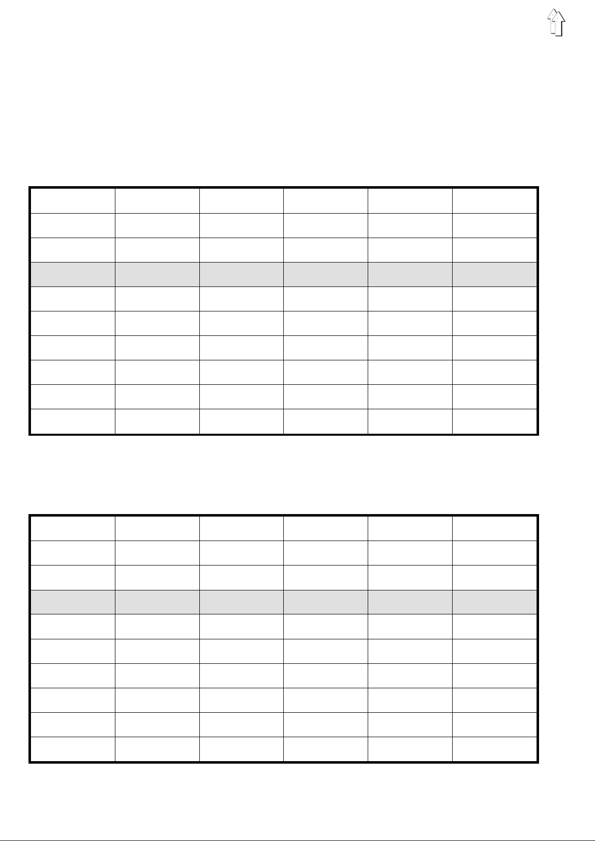
3. Size tables
In the following tables the basic sizes for the various countries are in
bold type and marked with BAS.
3.1 Sizes for 200-3
Ladies’ wear (DOB) 200-3
German French Italian GB USA Japanese
32 34 36 6 6 3
34 36 38 8 8 5
36 38 40 10 10 7
38 BAS 40 BAS 42 BAS 12 BAS 12 BAS 9 BAS
40 42 44 14 14 11
42 44 46 16 16 13
44 46 48 18 18 15
46 48 50 20 20 17
48 50 52 22 22 19
50 52 54 24 24 21
Men’s wear (HAKA) 200-3
German French Italian GB USA Japanese
44 44 36 34 38 2
46 46 38 36 39 3
48 48 40 38 40 4
50 BAS 50 BAS 40 BAS 40 BAS 41 BAS 5 BAS
52 52 44 42 42 6
54 54 46 44 43 7
56 56 48 46 44 8
58 58 50 48 45 9
60 60 52 50 46 10
62 62 54 52 47 11
8
Page 9
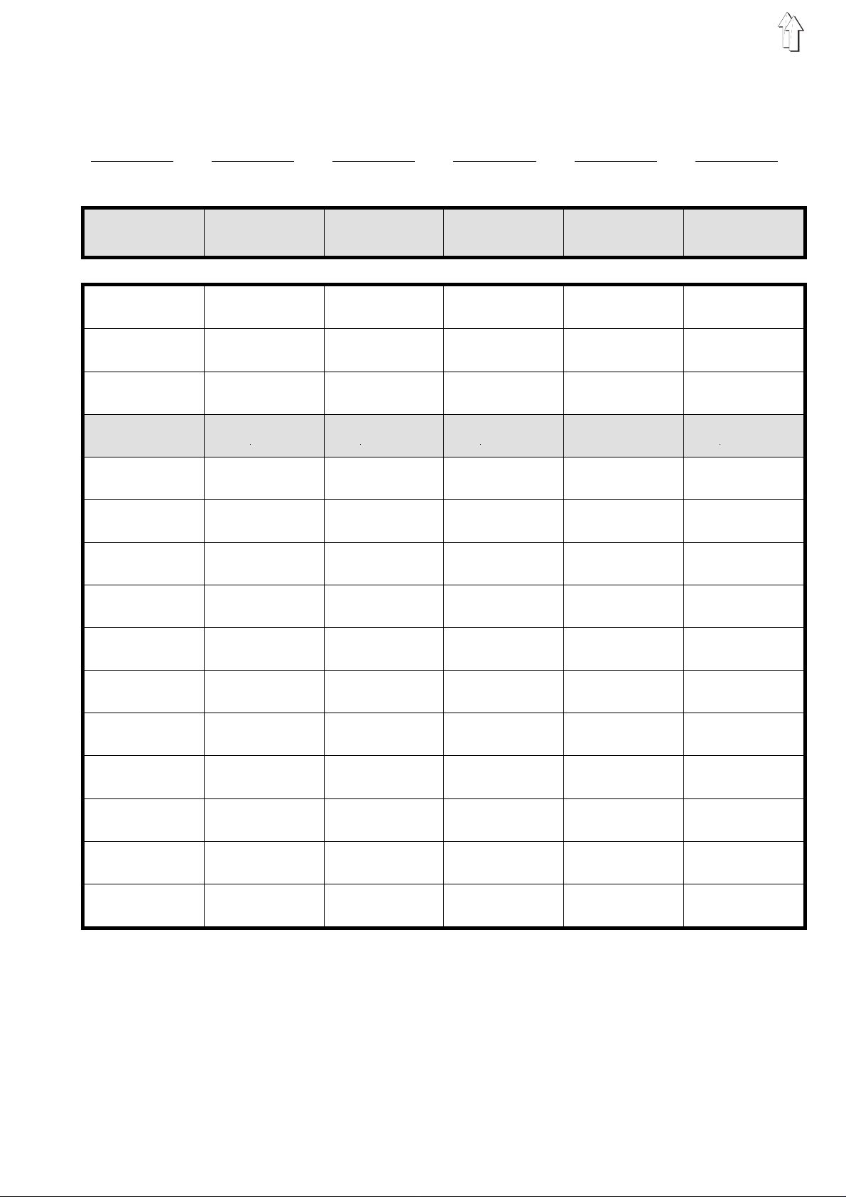
3.2 Sizes for 200-6
DOB (Women’ s outerwear )
Size Gr. 1 Size Gr. 2 Size Gr. 3 Size Gr. 4 Size Gr. 5 Size Gr. 6
German German French Italian GB/ USA Japanese
BAS 38 BAS 122 BAS 40 BAS 42 BAS 12 BAS 9
Ladies Girls Ladies Ladies Ladies Ladies
32 - 16/64 104 34 36 06 03
34 - 17/68 110 36 38 08 05
36 - 18/72 116 38 40 10 07
38 - 19/76 122 40 42 12 09
40 - 20/84 128 42 44 14 11
42 - 21/88 134 44 46 16 13
44 - 22/92 140 46 48 18 15
46 - 23/96 146 48 50 20 17
48 - 24/100 152 50 52 22 19
50 - 25/104 158 52 54 24 21
52 - 26/108 164 54 56 26 23
54 - 27/112 170 56 58 28 25
56 - 28/116 176 58 60 30 27
58 - 29/120 182 60 62 32 29
60 - 30/124 188 62 64 34 31
9
Page 10

3.2 Sizes for 200-6
HK (Men’s wear)
Size Gr. 1 Size Gr. 2 Size Gr. 3 Size Gr. 4 Size Gr. 5 Size Gr. 6
German A,B,CH,D, F, NL French Italian GB/ USA Japanese
BAS 50 BAS 50 BAS 50 BAS 40 BAS 40 BAS 5
men men men men men men
44 86/45/22
46 90/ 47/ 23
48 94/ 49/ 24
50 98/ 51/ 25
52 102/53/26
54 106/55/27
56 110/57/28
58 114/59/29
44 86/ 45/ 22
46 90/ 47/ 23
48 94/ 49/ 24
50 98/ 51/ 25
52 102/53/26
54 106/55/27
56 110/57/28
58 114/59/29
44 86/ 45/ 22
46 90/ 47/ 23
48 94/ 49/ 24
50 98/ 51/ 25
52 102/53/26
54 106/55/27
56 110/57/28
58 114/59/29
34 34 - 35 02
36 36 - 37 03
38 38 - 39 04
40 40 - 41 05
42 42 - 43 06
44 44 - 45 07
46 46 - 47 08
48 48 - 49 09
60 118/61/30
62 122/63/31
64 126/65/32
66 130/67/33
68 134/69/34
70 138/71/35
72 138/73/36
60 118/61/30
62 122/63/31
64 126/65/32
66 130/67/33
68 134/69/34
70 138/71/35
72 138/73/36
60 118/61/30
62 122/63/31
64 126/65/32
66 130/67/33
68 134/69/34
70 138/71/35
72 138/73/36
50 50 - 51 10
52 52 - 53 11
54 54 - 55 12
56 56 - 57 13
58 58- 59 14
60 60 - 61 15
62 62 - 63 16
10
Page 11
4. Base setting of the controls
4.1 200-3 controls
Depending on th e a pp l i c at i on of the control a de fi n ed ba s i c ad j us t me nt
must be made.
It is advisable to check this basic adjustment prior to starting the
machine.
After a reset it is imperative to check the basic adjustment!
200-3 controls
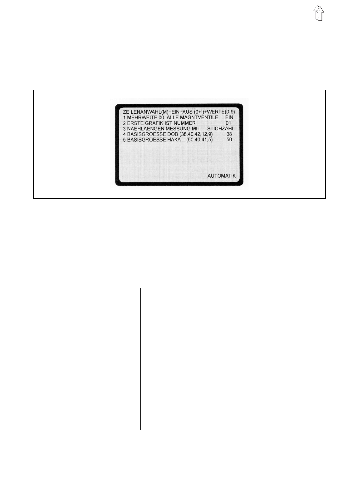
4.1.1 Selection of the size group
(valid for all programs /see size table page 8)
Calling up the basic adjustment:
–
Press key A.
–
Press key Y and keep depressed, also press key 0.
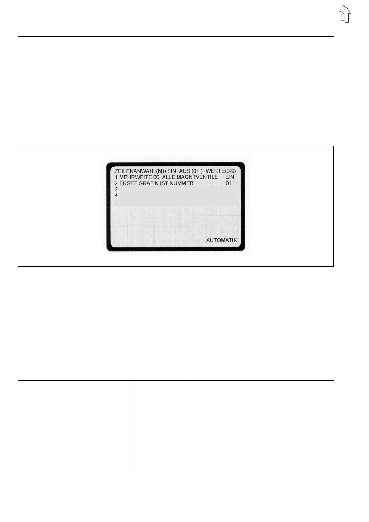
The basic ad jus t me nt of the control a pp ea rs on th e s c re en.
–
Switch ove r to fi e l d 5 usi n g k e y M.
The fields are to be set according to the specifications in the following
table.
Field Adjustment Remarks
1 FULLNESS 00, ALL
SOLENOID VALVES
2 FIRST GRAPHICS IS NO
3 SEWING LENGTH MEASURE MENT WITH
DISTANCE MEASUREMENT
STITCH NO./
ON/OFF
01/08
ON Changeover from
Switch over to field 2 using key M.
eg 01 Select the desired graphics.
(eg graphics 01 fo r pre - ga th er i n g)
Switch over to field 3 using key M.
STITCH NO. Changeover from
MENT to STITCH NO
Press key Y
key F.
Switch over to field 4 using key M.
OFF
to ON using key
DISTANCE MEASURE-
.:
and keep depre s s ed , a l so press
0-I.
4 BASIC SIZE DOB (38;40;42;12;9) eg 38 The basic size for DOB is being set.
The basic sizes for different countries
can be found in the
Switch over to field 5 using key M.
sizes
table (see page 8).
11
Page 12
Field Adjustment Remarks
5 BASIC SIZE HAKA (50;40;41;5) eg 50 The basic size for HAKA is being set.
The basic sizes for different countries can be
found in the
Press key A to quit the ba s ic ad j us t me nt .
sizes
table (see chapter 3.1).
4.2 200-6 controls
Depending on the application of the control a defined basic adjustment
must be made .
It is advisable to check this basic adjustment prior to starting the
machine.
After a reset it is imperative to check the basic adjustment!
Größengr uppe DO B (1-8) 1
Größengr uppe HA KA (1-8) 1
200-6 controls
4.1.2 Selection of the size group
(valid for al l p rog r am s /s e e si z e ta bl e pa ge 9/ 10 )
Calling up the basic adjustment:
–
Press key A.
–
Press key Y and keep depressed, also press key 0.
The basic adjustment of the control appears on the screen.
–
The M key select the next line.
The fields are to be set accordin g t o t he s pe c i fi ca t io ns i n th e
following table.
Field Adjustment Remarks
1 FULLNESS 00, ALL
SOLENOID VALVES
2 FIRST GRAPHICS IS NO
ON/OFF
01/08
ON
Changeover from
Switch ove r to fi e l d 2 usi n g k e y M.
eg 01 Selec t th e d es i r e d g rap hi c s .
(eg graphics 01 for pre-gathering)
The M key causes an ad v en c e t o t he next line.
OFF
to ON using key
0-I.
3 SIZE GROUP DOB (1-8) see the listed
table DOB
12
With the selection of one of the listed tables
automatically the
and the
(See page 9).
size row
basic size
determinant.
will be set
Page 13

Field Adjustment Remarks
4 SIZE GROUP HAKA (1-8) eg 01 The automatic mode is shown after pressing
the A key. The now selected size group is valid
for all progr am s . Th ei r b as e si z e i s shown,
e.g.050 BAS. The size group is stored
after erasing of a program.
In case of a
determination must be made again.
RESET
the base size
4.3 Selecting the base size per program
In principle a s i z e gro up is programmed as b ef or e with the
corresponding base size in the base setting
(see "calling up the base setting").
Additional l y af te r that another si ze s e r i es with the corres p on di n g b as e
size can be allocated to each single program
(see size table DOB/HAKA, sheet 9/10)
Programming of program-depending basis size
Sequence of operations Key Remarks
1. Call-up basis size as per
basis setting
2. Call-up programming-mode
3. Dele te pr o gr a m
4. Call-up Service display
5. Select
DOB
6. Sel c t g rou p o f si z e s
(see size table)
7. Push key for AUTOMATIC
8. Further run-off of program
refer to point 6.
HAKA
or
GR +
eG 050
Y +
Push both red keys; the control indicates
Y +
Y + O
M
1 - 8
A
Display shows
"ready for programming"
Monitor indi c a te s
The size group appears
HAKA/DOB
(see size table)
The figure will be brightly shown.
The selected figure will be shown.
The selected program with the selected size
series and correspond. basis size apears.
BAS
behind size .
"program will be deleted"
If a program as described above having a particular basis size will be deleted, the basis setting as determined in the basis setting will appear.
A deviating basis setting must be put-in newly.
13
Page 14

4.4 Allocation of the function keys
The f-funct i on s c an be al l o c at ed to th e s t ep s .
F-function Adjustment class Remarks
F1 on
F1 on
F2 on
F3 on ***
F4 on
F5 1
2...1 4
F6 1...14
5. Reset
F , 1 , O-I
F , 1 , O-I
F , 2 , O-I
F , 4 , O-I
F , 5 , 1
F , 5 , 2...14
F , 6 , 1
14
...
***Only valid for sewing units delivered before December 1993!
F3 on = F , 3 , O-I = stitch length reduction
550 - 16
550 - 12 - 12
550 - 12 - 12
550 - 12 - 12
550 - 12 - 12
550 - 12 - 12
-----
-----
needle thread te ns i o n i s loosened
facing strip is fed
facing strip is out
not allocated
speed reduction
stitch length reduction
not allocated
not allocated
Reset
A
–
–
Sequence of operations:
–
–
–
–
–
–
is required
when all prog r am s i n t he c on tr o l are to be erased
when an error occ u r s th at c an no t b e re me di e d
Press both red keys and
Turn off main switch, and wa it a pp r ox. 10 seconds.
Turn on main switch , a nd do
Release the two red keys onl y, when the bas i c ad j us t me nt
pattern appears on the screen.
All programs i n th e c o nt r ol a r e e r ase d.
Check the basic adjustment!
keep depressed
not release
.
the two red keys.
14
Page 15

6. Programming instructions:
pre-gathering the sleeve head / setting the sleeve
200-3 controls 200-6 controls
038
The sewing program is set up in the basic size in
is mirrored an d g rad ed automatical l y.
The control measures the sub s ec t i on s when sewing the i n di v idual
steps and incorporates them automatically into the program.
Sequence of operations Keys Remarks
1. Check the basic adjustme nt .
2. Select pr og r am nu mb er.
Enter the program number.
(eg progr.no. 01)
3. Select size.
Enter the siz e.
(eg si ze 38 200-3)
(eg size 038 200-6)
4. Call up the p rog r am min g m od e.
A
Y + 0
P
0 , 1
GR
3 , 8
0 , 3 , 8
Y +
Only for the first machine start or after a
Reset.
To check the basic adjustment:
see chapter 4 / 4.2.
PROG.NO. is hig hl i g ht ed .
possible program numbers:
200-3 contro l s
200-6 contro l s
SIZE is highlighted.
Basic sizes: DOB 38, HK 50
DOB 038, HK 050
Press both red keys.
The control indicates
READY TO BE PROGRAMMED.
01...20
01...15
teach-in mode
, and
5. Erase the f or m er p r og r am .
6. Select the graphics. Press the key until the graphics 01 (ellipse)
Y +
Prior to sett ing up a n ew pr o gra m a l wa y s
press the eras i n g k e ys .
appears.
15
Page 16

Sequence of operations Keys Remarks
7. Select th e s t ar t ing s l ee v e.
8. Lay the seam beginning
of the selected sleeve under the
foot.
9. Select ga thering intensi t y.
Enter the gathering intensity.
10. Sew step 1. During sewing the number of stitches is being
11. Select grading (where
neces sary)
En ter the gradin g.
(eg grading val u e 0 2)
RL
MW
0...14
GD
0 , 2
In the case of a wrong choice press the
erasing ke ys ( see 5.)
Re-select th e s t arting sleeve.
Gathering intensity = Fullness
The gathering intensity is to be determined
from experimental values.
counted and au to ma ti cally stored.
The value indicates how much the sewing
length of th e s t ep c ha ng es with each
grading value.
Example:
the designer specifies a change in seam
length of 5 m m f r om on e si z e to th e n ex t .
With a stit c h l e ng th of 2. 5 mm this
corresponds to 2 stitches. Thus, the grading
02 is entered.
When calling up another size the section is
automatically increased or decreased by the
set grading.
12. Call up th e n ext
Repea t point s 9. to 1 2.
13. Switch off the stitch
last
14. Enter the sleeve end.
step.
S
0-I
E
Per sleeve a maximum step. of 13 steps can be
entered.
ATTENTION!
In the case of more than 13 steps the sleeve
cannot be mir r o red l at er.
Press the two red keys to get back to the
1st program step (
certain program steps
The next step is called up using key S.
SEWING
In the
field the number of stitches
Behind the number of stitches
OFF
appears.
Stitch counting is switched off during the
program ste p so that the operat or c a n
determine the seam end manually.
During sewing the deactivated stitch
counting is i n di ca te d i n th e
LENGTH
During sewing of the last step, E (end)
must be entered (program end).
In the
Underneath the graphics appears
END, CONTINUE.
field by brackets and
END
field appears
to check or to later change
).
OFF
MIRR.,
LENGTH
.
counting dur i ng th e
is in brackets.
SEWING
end
.
last
16
Page 17

Sequence of operations Keys Remarks
MIRR
.: sleeve is b eing mirrored.
(see
END
: only the piece just created
is bei ng stor ed.
(see:
CONTINUE
the
Enter furthe r st eps.
15.
)
only store right/left sleeve
: press key E until (--) appears in
END
field.
)
15. Mirror the sleeve.
16. Copy the set of sizes.
17. The machine is ready to sew. The ellipse with the laid down steps is
Only storing the right/left sleeve
Only store th e r i g ht /l e ft s l ee ve.
SP
C
E
The program for the right/left sleeve is
created by mi rr o ri ng an d t hen stored.
Underneath the gra ph i cs ap pe ar s
COPY, AUTOMATIC
COPY
: copying set of sizes (see
AUTOMATIC:
basic siz e
The created program is copied into each size
of the application (DOB/HAKA).
The control switches over to automatic
operation.
displayed.
When pressing key E again, only the program
created for the right or left sleeve is stored.
END
In the
Mirroring i s no longer possi bl e .
Underneath the gra ph i cs ap pe ar s
COPY, AUTOMATIC
Continue with
see:
field appe ars
.
only incorporating the
END
.
.
16.
16.
)
Only copying the basic size
Only copy the basic size.
Error message Remedy
ER.SEWING LENGTH GRAD
PROG.NOT OK
PROG. HAS NO END
<
A
The grading v alu e m us t al w ays b e s m all e r th an th e se wi n g
length of th e s t ep .
Sew the step or enter the sewing length.
The program contains invalid values.
Check the values and correct the invalid value.
The programmi n g m ode cannot be qui t.
Press E key, then press the A key.
No reaction !
Press both
Erase the pr o gra m a nd then press the A key.
red
By pressing key A the created program
is only copi ed an d s t or e d i n th e b as i c s i z e .
Continue with 17.
keys.
17
Page 18

Programming instructions rei nforcing
18
The sewing program is set up in the basic size in
is automatically mirrored and graded.
The control measures the subsections during sewing of the steps and
automatically incorporates them in the program.
During sewing the tape feeder automatically feeds the reinforcement
tape.
After a programmed number of stitches the tape scissors cut the
reinforcement tape within the seam.
teach-in mode
, and
Page 19

Sequence of operations Keys Remarks
1. Load the re inforcement tape . Loading the t ap e
2. Check the basic adjustme nt .
3. Select pr og r am nu mb er.
Enter the program number.
(eg progr. no. 01)
4. Select size.
Enter the siz e.
(eg 38)
5. Call up the p rog r am min g
mode.
6. Erase the f or m er p r og r am .
7. Select the graphics. Press the key until graphics 08 appears.
A
Y
+ 0
P
0 , 1
GR
3 , 8
Y
+ Press both red keys.
Y
+ Pri or t o s e tt i ng up a new program, al w ay s
Only at the first machine start or after a Reset.
Checking the basic adjustment:
see chapter 4.1/4.2.
PROGR.NO.
possible program numbers:
SIZE
is highlighted.
Basic sizes: D OB 3 8, HK 50
The control displays
PROGRAMMED
press the eras i n g k e ys .
is highlighted.
01...20
READY TO BE
.
8. Select the starting piece.
9. Place the s e am be gi n ni n g o f
the selected pi e c e u nd er
the foot.
10. Select ga th er i n g i n te ns ity.
Enter the gathering intensi t y.
11. Sew step 1. During sewing th e n um be r of stitches is be i ng
12. Select gr a di n g (i f ne c es s a ry ) .
Enter the gradin g
(eg grading 0 2)
RL
MW
0...14
GD
0 , 2
When the wrong piece was selected,
press the eras i n g k e ys ( see 6.)
Re-select the starting piece.
Gathering intensity = Fullness
The gatherin g i n te nsi t y i s to be de te r mined
from experime ntal values.
counted and automatically stored.
ATTENTION !
In the first st ep , t he
must be
The value indicates how much the sewing
length of the step changes with each grading
value.
Example:
the designer specifies a change in seam length
of 5 mm from on e si z e to th e n ex t .
With a stitch length of 2.5 mm this corresponds
to 2 stitches . T hu s, the grading 02 is en te r ed .
When calling up another size the section is
automatical l y i ncr e as e d o r de c r ea s ed by the
set grading.
2 stitches
minimum
.
sewing length
13. Select step 2.
S
In the
STEP
field 02 is displayed.
19
Page 20

Sequence of operations Keys Remarks
14. Switch on the tape feeder.
Activate the tape feeder.
15. Select gathering intensity.
Enter the gathering intensity.
16. Sew step 2.
17. Select grading (if necessary).
Enter the grading (eg grading 02)
18. Select step 3.
19. Select and enter the gathering
in tensit y.
F , 1
0-I
MW
0...14
GD
0 , 2
S
MW
15 stitches
12.
STEP
10.
OFF
is highlighted.
.
field 04 is highlighted.
In field F1
In field F1 ON is highlig ht ed .
The reinforcement tape is fed.
The flip switch A at the feeding attachment
must be at on (centre positi o n).
The gathering intensity is to be
determined from experimental values.
ATTENTION !
In the 2nd step , t he mi n i mu m se wi n g l e ng th
must be
see
When the 3rd s t ep i s s ele c te d, step 4
appears.
Step 3 is created automatic a l l y by t he
control.
In the
see
20. Sew step 4.
21. Select and enter the grading.
22. Program further steps.
23. Cut the reinfo rc em en t t ape.
Activate the tape cutt er.
24. Sew up to the end of the
pi ece.
GD
F , 2
0-I
12.
see
ATTENTION !
Each program must contain a
5 steps
Per piece a ma x imu m of 13 steps can be
entered.
With more than 13 steps the piece
cannot be mir r o red l at er.
In field
In field
The reinforcement tape is cut closely
above the funnel.
ATTENTION!
Enter no mor e s t ep s .
Otherwise, mirroring is no longer possible.
ATTENTION !
The last st ep mu s t contain
15 stitches
The number of stitches is counted and
automatically stored.
.
F2 OFF
F2 ON
is highlig ht ed .
.
is highlighted.
minimum of
a minimum of
25. Actuate the thread trimmer.
20
During the last step of the program the
stitch counting is switched off so that the
operator can manually determine
the seam end.
Page 21
Sequence of operations Keys Remarks
26. Enter the p i ec e en d.
27. Mirror the piece.
28. Copy the set of sizes.
29. The machine is ready to sew. The graphics with the laid down steps is
E
SP
C
The control automatically creates
another step.
END
In the
Underneath the gra ph i cs ap pe ar s
MIRR., END, CONTINUE.
MIRR.
(see
END :
is bei ng stor ed.
Mirroring is not possible .
(see:
CONTINUE:
the
Enter furthe r st eps.
The program for the right/left piece is
created by mi rr o ri ng an d t hen stored.
Underneath the gra ph i cs ap pe ar s
COPY, AUTOMA TIC.
COPY:
AUTOMATIC:
basic siz e
The created program is copied into
each size of th e a pp l i cation (DOB/
HAKA).
displayed.
field appe ars
: sleeve is b eing mirrored.
27.
)
only the piec e j ust created
only store right/left piece
press key Euntil (--) appears in
END
copying the set of sizes (see 28.)
see:
end
.
field.
only incorporating the
)
Only storing the right/left piece
Only store th e r i g ht /l e ft pi e c e.
Only copying the basic size
Only copy the basic size.
Error message Remedy
ER.SEWING LENGTH GRAD <
SEWING LENGTH >14 ENTER
E
A
The grading value must be smaller than the sewing
length. Sew t he s te p o r en te r th e s e win g l e ng th .
In the called u p s t ep th e s e win g l e ng th v alu e m us t
be larger than 14. Correct the sewing length.
When pressing key E again, only t he
program created for the right or left
piece is st ore d.
Mirroring i s no longer possi bl e .
END
In the
Underneath the gra ph i cs ap pe ar s
COPY, AUTOM A TIC .
Continue with
By pressing key A the created program
is only copi ed an d s t or e d i n th e
basic size.
Continue with 29.
field appe ars
28.
END
.
PROG.NOT O K
PROG. HAS NO END
The program contains invalid values.
Check the values and correct the invalid value.
Press key E or both
Then delete p r og r am an d subsequently p ush key A.
red
keys.
21
Page 22

7. Changing an existing program
7.1 Changing the enti re set of si zes
It is necessary to make a change in an existing program.
The change i s to be effec t i ve i n
Sequence of operations Keys Remarks
all
sizes.
1. Call up the program to be
changed. (eg pr o gr. no. 01)
2. Select the basic size.
(eg si ze 38 fo r DOB 20 0-3)
(eg size 03 8 f or DOB 200-6)
3. Call up the programming mode.
4. Call up the step to be changed
5. Make the change. eg enter another gathering value.
6. Call up the last step of the 1st
programmed piece.
7. Mirror the piece.
8. Copy the set of sizes.
P
0 , 1
GR
3 , 8
0 , 3 , 8
Y
+
S
S
SP
C
Basic sizes:
DOB 38; HK 50
DOB 038; HK 0 50
Press both red keys.
The control displays
PROGRAMMED
Press key S until the st ep to be changed
appears.
end appears i n th e
Underneath the graphics appears
MIRR.; END, CONTINUE
If this is not the case, press key E until
END, CONTINUE
The change i s tra ns f er re d to the
mirrored sleeve.
underneath the graphics.
The change i s tra ns f er re d to all
sizes.
READY TO BE
.
END
field.
.
appears.
COPY, AU TO MATI C
MIRR.,
appears
7.2 Changing only one size
It is necessary to make a change in an existing program.
The change i s to be effec t i ve j u s t i n
Sequence of operations Keys Remarks
1. Call up the program to be changed.
(eg progr. no. 01)
2. Call up the size to be changed.
(eg si ze 40 20 0-3)
(eg si ze 040 2 00-6)
3. Call up the programming mode.
4. Call up the step to be changed.
5. Make the change. eg enter another gathering value.
6. Call up the last step of the
P
0 , 1
GR
4 , 0
0 , 4 , 0
Y +
S
S
Press both red keys.
The control displays
GRAMMED
Press key S until the step to be changed appears.
end appears in the 1st programmed piece.
END
field.
Underneath the graphics appears
CONTINUE
If this is not the case, press key E until
END, CONTINUE
one
.
.
size.
READY TO BE PRO-
appears.
MIRR., END,
MIRR.,
22
Page 23

Sequence of operations Keys Remarks
7. Mirror the p i ec e .
8. Switch o n t he au to ma ti c
SP
A
The change is transferred to the mirrored
piece.
the graphics .
The change is made operation.
in the called up
size only.
7.3 Changing only the right or left piece
It is necessary to make a cha ng e i n an ex i sting program.
The change is just to be effective for the
Sequence of operations Keys Remarks
1. Call up the program to be changed.
(eg progr. no. 01)
2. Select the basic size.
(eg si ze 38 for DO B 20 0-3)
(eg size 038 for DOB 200-6)
3. Call up the p rog r am min g m od e.
P
0 , 1
GR
3 , 8
0 , 3 , 8
Y
+
Basic sizes:
(eg si ze 38 for DO B; H K 50 )
(eg size 038 for DOB; HK 050
Press both red keys.
The control indicates
PROGRAMMED
END, AUTOM ATIC
right or left
READY TO BE
.
appears under n ea th
piece.
4. Call up the s t ep to be cha ng ed
of the right or l e ft pi e c e.
5. Make the change. eg enter anot he r ga th er i n g v a lue.
6. Switch o n t he au to ma ti c
operation.
S
A
Press key S until the ste p to be changed of
the right or left piece appears.
end
appears in the
END
field in the l a s t s t ep of th e 1 s t p i ec e .
Again press key S to change over to the
2nd piece.
The change is made in the right or left piece
only.
ATTENTION!
After the changes of point 5. have been made,
mirroring an d c o py in g i n to the set of sizes i s no
longer allowed.
7.4 Selecting and Changing the half size with the 200-6 controls
See size table DOB / HAKA (sheet 9/10)
All size entries must be three digit.
eg size 102 key 102
eg siz e 52 key 052
After the programming of the base size, all half sizes (as listed in the
size table after the base size) are given the same values.
If some points in the half sizes must be changed, this can be done as
described in th e i n s tr u c tions item 7.1 "c h an gi n g a n e x is ti n g p r og am " .
Attention!
Altered half sizes
change in the base size and the pressing of the C key.
In a program alre ad y ge ne r at ed wi t h a l te red ha l f s iz e s
no longer be used. With a change of the BAS size and altered half
sizes, the A key is always to be used to enter the automatic mode.
If necessary, the sizes must be changed individually.
are made to con fo r m t o t he ba s e s i ze again after a
the C key may
23
Page 24

8. Program sequence
Up to 6 indi v idu al p r og r am s c an be l i nk e d i n a
After the program sequence has been activated, the control uses the
programs of the sequence successively.
A total of 5 program sequences (A-E) can be stored.
Application example:
On a garment t he r i gh t a rmh ol e , neck opening, an d t he l ef t a r mh ol e
are to be reinforced successively.
Both armholes are to be reinforced additionally using reinforcement
tape.
Initially, the operator s e ts u p t he th r ee pro gr a ms (P 01 , P 02 , P 03 ) fo r
the individual operations.
P 01: reinforcing the right armhole with tape (without mirroring)
P 02: reinforci n g the neck openi ng wi t ho ut ta pe ( wi t ho ut mi r ro r i ng )
P 03: reinforcing the left armhole with tape (without mirroring)
Then, the th ree pr o gra ms ( P 01 , P 02 , P 03 ) ar e l i nke d up to form a
program sequence.
program sequence
.
8.1 Setting up a program sequence
Sequence of operations Keys Remarks
1. Call up the program sequence
mode. (
2. Select the program sequence (A-E). Press the key until the desired program
3. Select the place in the
program sequence.
4. Enter the p r og r am nu mb er.
200-3 con trols
200-6 con trols
in automatic operation
Y +
)
P
1...20
1...15
The program sequence (A-E) called up last
is highlighted.
sequence (A-E) is highlighted.
Place 1 in t he pr o gra m s e qu en c e i s
highlighted.
After input of the program numb er f or
place 1, sel e c t t he ne x t p l ac e usi n g k e y P.
Enter the respective program number.
In each progr a m s e qu en c e 6 pro gr a ms
can be entered.
As long as t he pr o gra m s e qu en c e i s n ot qu i t,
each program place can be written over (input
1...20
or
1...15
) or erased (input 0).
24
Page 25

Sequence of operations Keys Remarks
5. Call up an ot he r pr o gr a m se quence. See 2.
5 program sequences
(A-E) can be called up successively.
6. Quit the pr og r am sequence mode.
A
The first pro gr a m o f t he pr o gra m s e qu en c e i s
called up.
In the field
sor program is displayed.
After sewing the program the successor
program is ca l l ed up .
The program sequence is aborted when a
program is selected directly.
From program E-PROM dated
up there are tw o ways to quit th e p r og ram
sequence mode:
- by pressing the key
- by selecti ng a p r og ram that is not par t of
the sequence.
8.2 Activating the program sequence
Sequence of operations Keys Remarks
1. Call up the program sequence mode.
in automatic operation
(
)
Y+ The program sequenc e ca l l ed up l as t ( A- E )
is highlighted.
SUCCESSOR PROGR.
July 24, 1993
0-I
the succes-
2. Select the program sequence (A-E). Press the k ey until the desi re d p r og ram
sequence (A-E) is highlighted.
ATTENTION!
When a program place was selected using key
P
, be sure to press key P until the last
program of the sequence is highlighted.
Otherwise, th e p r og ram s to th e r i g ht of th e
highlighted pr o gr a m a re b ei n g e r as e d f rom the
sequence.
3. Activate the program sequence.
A
8.3 Erasing the program sequence
Sequence of operations Keys Remarks
1. Call up the p rog r am seq ue nc e mo de .
in automatic operation
(
2. Select the program sequen c e ( A- E ). Press the key u nt i l th e d es i re d p r og r am
3. Erase the program sequence.
4. Call up an ot he r pr o gr a m se quence. See 2.
)
Y
+
P
0
The program sequence (A-E) called up last
is highlig ht ed .
sequence (A-E) is highlighted.
The first pla c e o f t he pr o gr a m sequence is
highlighted .
00
appears on the fi r st place of the pr o gra m
sequence.
5. Quit the pr og r am sequence mode. A The pro gr a m s e wn l ast appears.
25
Page 26

9. Memory card
The memory ca r d i s used for long-t er m pre s er va ti o n ( a pp r ox. 4 years)
of programs.
Programs can be transferred from this memory card to other machines.
The control transfers the p r og ram s to th e m em or y card.
Memorized programs can again be loaded from the card into the
control.
9.1 T ran sferring pr ograms t o the mem ory card
The programs s et up wi t h t he c on tr o l are tr a ns f er re d t o the memory
card during the automatic operation.
They are sec ur e d a nd , i f ne c ess a r y, can be loaded as o ft en as d es i re d
into the cont rol .
Sequence of operations Keys Remarks
1. Insert the card in the arrow indicated direction. Green
arrow poi nts downwa rds.
2. Enter the card no. (eg card no. 01) 0 , 1 The card number is displayed.
3. Transfer the data.
Y +
4. Remove th e m em or y c a r d. Label the car d an d k e ep i t i n th e
Display: see figure.
In the case of an empty memor y car d
RAM CARD E MP T Y ap pe ars .
ATTENTION!
The directi on of transfer cann ot be c ha ng ed
any more.
During the transfer process a row of
crosses is displayed at the bottom of the
screen. The transfer process is completed
when REMOVE MEMORY CARD appears.
envelope.
Error message Remedy
RAM CARD EMPTY
TRANSFER ERROR CARD
WITHOUT PROGRAMS
26
The message i n dic a te s th at no pr o gr a ms are yet on the me mo ry
card.
When the card is removed too soon, the data on the card are
being erased .
Re-insert the card.
Repeat the memorizing process.
Page 27

9.2 Loading the programs into the control
The programs memorized on the card are being transferred to the
control.
Sequence of operations Keys Remarks
1. Insert the card in the arrow indic ated direc tio n.
Green arrow po int s do wn wa rds .
2. Change the d ir ect i on of
transfer
3. Transfer the data.
Y +
4. Remove the me mo r y c ar d . Keep the card i n i t s envelope.
Error message Remedy
RAM CARD EMPTY
BOX EMPTY
The message indicates that no programs are on the memory
card.
The message indicates that all data in the control are erased.
In the case of an empty memory card
RAM CARD EMPTY appears.
Display: see figure.
The direction o f t he ar ro w c h an ge s .
During the tran s fe r pr o ces s a row of c ros s e s i s
displayed a t t he bo tt om of the screen.
The transfer process is completed,
when REMOVE CARD appears.
TRANSFER ERROR
ALL PROGRAMS IN THE BOX
ARE ERASED
When the car d i s re mo v ed to o s o on , a l l da ta i n t he c on tr o l
are being erased.
Re-insert th e c a rd.
ATTENTION!
Repeat the transfer process
starting wit h 2 . ( C ha ng i ng th e d ir ect i on of tr a nsf er ! ).
27
Page 28

10. Entering text
Display for text input
The text inp ut mo de s er ves to provide th e i n di v idual programs w i th
designations, comments, notes, etc.
It is thus ea s i er for the user to l oc a te c ertain programs.
For the call ed up pr o gr a ms 2 l i ne s of te x t w i th 38 c ha r acters each can
be entered vi a th e k e y s of the control.
The function of the keys is displayed on the screen.
By pressing the Shift-key the key function is changed from letters to
digits and c h ar a cte r s .
Display after a change of the key function
Sequence of operations Keys Remarks
1. Call up the desired program.
2. Call up the text input mode.
Y +
The function of the keys is displayed on the
screen.
3. Enter the text.. The entered t ex t ap pe ar s a bo ve the graphics.
4. Quit the text input mode. A
28
Page 29
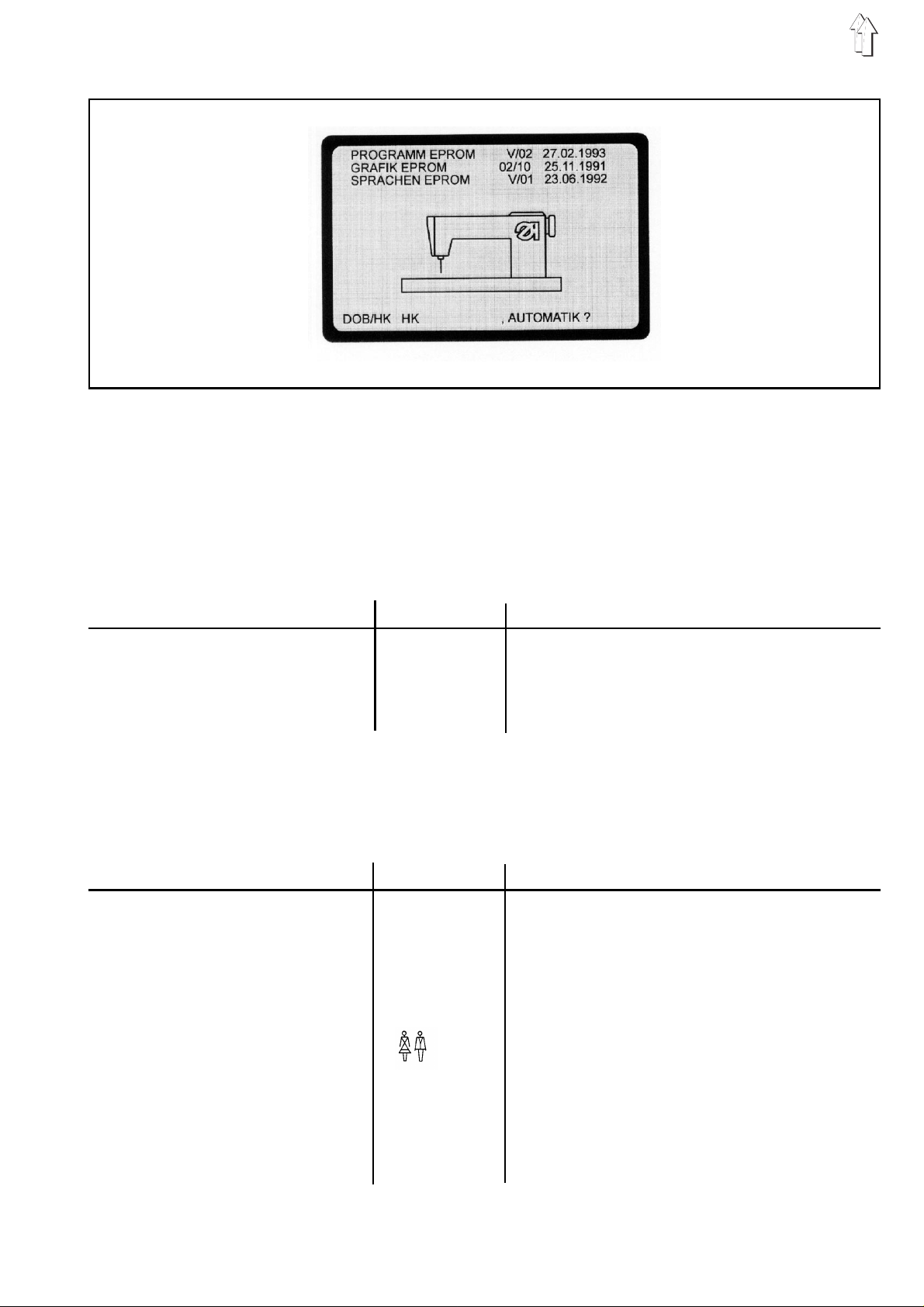
1 1. Calling up the EPROM states
The EPROM states indicate which program versions exist in the
respective control.
These specif i c at i on s are i mp or t an t, as t he pr o grams are constan tl y
being revised. As a result of this, certain functions change from
EPROM to EPROM.
In this programming manual we refer to such changes by specifying
the correspon di n g E P R O M s t at e.
EPROM. Era s ab le P r o gr a mm ab l e R ea d O n l y Me mory
Sequence of operations Keys Remarks
Call up the EP R OM s t at es . Y Keep k ey Y depre s s ed.
Turn off main switch.
Keep key Y depressed.
Turn on main switch .
Keep key Y depressed until the screen starting
pattern with t he E PR OM s ta te s ap pe ar s.
1 1.1 Pr eselect ing the appl ication ( DOB/HK )
In the on-scre en di s p l ay sh own in 11. the application (D O B /H K ) i s
preselected f or a l l un de fi n ed pr o gra ms a s we ll .
Sequence of operations Keys Remarks
1. Call up th e EP ROM states. Y Keep key Y depress ed .
Turn off main switch.
Keep key Y depressed.
Turn off main switch.
Keep key Y depressed until the screen starting
pattern with t he E PR OM s ta te s ap pe ar s.
2. Change the a ppl i c at ion . In the field DO B/ HK e i th er DOB or HK is hig hlighted.
This means that all undefined programs are
intended for the application DOB or HK.
3. Switch o n t he au to ma ti c
operation.
A In the field DOB/HK the
selected application (DOB
or HK) is hig hl i g ht ed .
29
Page 30
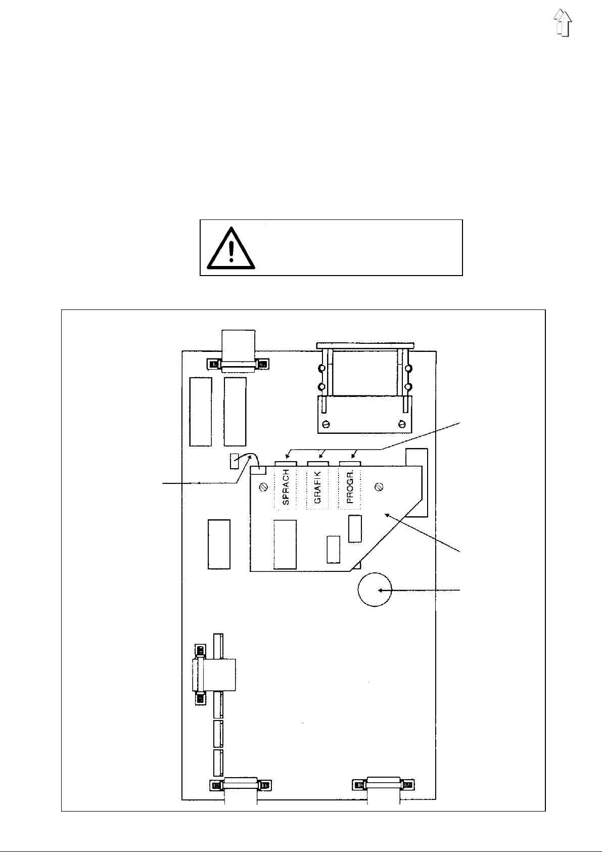
11.2 Replacing the EPROMs (200-6)
–
Turn the main switch off.
–
Pull the 220V mains plug and the 30 pin plug from the controls.
–
Pull the controls from the mounting.
–
Screw off the bottom plate of the controls.
–
Pull off the connecting lead to the memory board.
–
Srew off the memory board and pull carefully from the base.
–
Pull the EPROMs from the holders and insert new EPROMs.
–
Insert the memory board into the base and screw fast.
–
Plug on the co nn ec t i ng l ea d t o t he memory board.
All programs are erased when
the memory board is removed.
Connecting
lead
EPROMS
- Language
- Graphics
- Progam
Memory
board
Battery
30
Page 31

12. Setting the starting position of the ellipse
The ellipse (graphics 01) is divided up into 52 sections (00 to 51).
The starting position applies to all sizes of a program.
The adjustme nt c an on l y be ma de i n t he pr o gra mm i ng mo de wi t h
called up basic size.
Sequence of operations Keys Remarks
1. Call up th e p rog r am mi n gm od e.
Y +
2. Call up the s t art i ng po s iti o n. Y + M Display: eg STARTING POS.: 00
3. Change the s t arting positio n. M Press the key M un ti l t he de s i red s ta r ti n g
4. Showing t he ne w s t ar t i ng po s iti o n. A The control sw itches back to au to ma ti c o pe r at i -
Examples:
STARTING POS .: 13 STARTING PO S.: 07
Press both red keys.
The control displays READY TO BE
PROGRAMMED.
position is displayed in the field
STARTING POS.:.
on.
The graphics ap pe ar s w i th th e c h an ge d s t arting
position.
31
Page 32

13. Changing the language of the on-screen text
The language of the on-screen te x t can only be chan ge d d uri n g
automatic operation.
Two different language E P R O Ms with 8 language s ea c h a re available:
200-3 200-6
EPROM-Set 1: EPROM-Set 2: EP R OM - S et 1: EPROM-Set 2:
9850 550008 E P 01 9850 550008 E P 02 9850 55 00 28 E P 01 9850 55 0028 EP02
German German German German
English English English English
Frensh Frensh Frensh Frensh
Spanish Turkish Spanish Turkish
Italian Romanian Italian Romanian
Portuguese Portuguese
Swedish Swedish
Polish Polish
EPROM-Set 3: EPROM-Set 4: EP R OM - S et 3: EPROM-Set 4:
9850 550008 E P 03 9850 550008 E P 04 9850 55 00 28 E P 03 9850 55 0028 EP04
English German English German
Japanese Bulgarian Japanese Bulgarian
EPROM-Set 5: EPROM-Set 6: EP R OM - S et 5: EPROM-Set 6:
9850 550008 E P 05 9850 550008 E P 06 9850 55 00 28 E P 05 9850 55 0028 EP06
German English German Eng l i s h
Russian Chinese Russian Chinese
Sequence of operations Keys Remarks
1. Call up l a ng ua ge s. Y + P The language s are l i s te d.
The current l a ng ua ge i s hi g hl i g ht ed .
2. Select another language. Y + P Keep key Y depressed and press key P until
the desired language is highlighted.
3. Change the language. A The on-screen text is in the selected language.
32
Page 33

14. Adjusting the gathering values to different materials /
Percental change of the crimp value
From program EPROM dated July 24, 1993 up the gathering values of
an existing program can be adjusted to different materials.
Via the program ad jus t me nt the gathering v al u es a r e i n c rea s ed or
decreased i n a ll pr o gram steps by a cer t ai n pe r cen ta ge.
(max +14% / -14%)
The program adjustment is done during automatic operation.
Application example:
A sewing program exists for a piece in a defined material.
This piece is now to be sewn with another material with other
properties.
During sewi ng of th e p i ec e i t t ur n s out that the gath eri n g v a l ue s of th e
program are too small or too large for the new material.
Via the program ad jus t me nt the gathering v al u es o f t he en ti re pr o gr a m
must thus be i nc r e ase d or decreased by a cer t ai n pe r cen tage.
The operator en te rs th i s pe rc en ta ge .
Then, the control automatically increases or decreases the gathering
values in all program steps by the entered percentage.
Now, the program is adj u sted to the different ma te r i al p rop er t i es .
Sequence of operations Keys Remarks
1. Select ch an ge of gathering
value in % .
2. Enter the pe rc en ta ge . 0...14 The gatherin g values can only be ad j us t ed
3. Select increase or decrease. 0-I The display changes between
4. Switch on the automatic operation. A The %-value (except value 00) is displayed
GD Underneath the GATH.VALUE field % 00
is highlig ht ed .
between max + 1 4% / - 1 4% .
+ (increase ) an d - (decrease).
during sewi ng un de r ne at h t he G ATH.VALUE
field.
ATTENTION!
When re-selecting the called up program
number or anot he r pro gr a m n um be r th e
%-value is reset to 00.
15. Determining the gathering value
The gatherin g value or fullnes s c a n e i th er b e d etermined from
experimental values or by testing.
Sequence of operations Keys Remarks
1. Switch o n t he ma nu al
operation.
2. Enter the est i ma te d gathering
value.
M
0...14 Estimate and enter the gathering value or
fullness for a section.
3. Sew the section. If necessary, sew the section without threads.
4.Check whether notch is on notch. When the notches are not accurately
superposed, change the gathering value.
Repeat the pr oce du r e w i th a n ew gathering
value starti ng with 2. until notch i s on no tc h .
5. Switch o n t he au to ma ti c
operation
A The contro l sw itches over to au to ma ti c -
operation.
33
Page 34
16. Service
ATTENTION!
Any work on th e e l ect r i cal e qu i pm en t o f t he ma chi n e
must only be performed by skilled electricians or
accordingly trained personnel.
16.1 Correcting the on-scre en display ( 200-3 / 2 00-6)
The accurate ad j us t me nt and alignment of th e o n- s cr e en di s p l ay i s
performed v i a t he s cr ee n t es t pa tt er n .
The necessary corrections are carried out using the potentiometers on
the monitor board.
Caution Hi gh - Voltage !
Do not touch live parts.
Only use insulated tools.
Sequence of operations Remarks
1. Insert the memory card
in the arrow- ind icated direct ion.
Green arrow points downwards.
2. Turn on main switch.
To correct the screen display:
3. Turn off main switch.
4. Remove the memory card.
5. Mark the entire visible screen
cutout on the glass pane of
the screen using a pencil.
6. Remove the 220 Volt mains plug
and the 30-pin-plug from the control.
7. Remove th e c o nt r ol from its holder.
Main switch is turned off.
The screen tes t pa ttern appears.
It consists of a grid of squares.
ATTENTION !
With correct adjustment the distance of the square grid to the
lower screen ed ge must be slightly larger tha n t o t he up per edge.
Otherwise, the bottom line of the screen displays is not visible.
To make sure that the visible screen cutout can still be
outlined after the hood has been removed.
8. Unscrew the hood.
9. Insert the memory card
in the arrow- ind icated direct ion.
Green arrow points downwards.
10. Insert the 220 Volt mains
pl ug into the con trol.
11. Perform the correcti on s us i n g
the po tentiomet ers.
34
The screen tes t pa ttern appears.
For correction possibilities: see figure of the potentiometers on
the monitor bo ar d .
The monitor board is installed
upright late r all y b es i d e t he s cr ee n.
Page 35
Potentiometers on the monitor board (200-3 / 200-6):
Regulating the background
brightness
Adjusting the intensity
Setting the display height
16.2 Changing the battery of the memory card
Stretchin g/ c om pressing the
display in vertical direction
Stop runnin g t hr o ug h
display
Rectifying the top text line
Beam current limitation
Shifting th e d i spl a y to th e
right/left
Setting the display width
See instructions on the memory card.
ATTENTION !
Programs memorized on the ca r d a re b ei n g e r as e d
when the battery is changed.
Prior to chan gi n g t he battery load th e p rog r am s i nt o
a control !
35
Page 36

16.3 Changing the fus e (200-3 / 200-6)
–
Turn off main switch.
–
Remove the 22 0 Volt mains p l ug an d 3 0- p i n-p l ug fr o m t he c on trol.
–
Remove the control from its holder.
–
Unscrew the bottom cover plate of the control.
–
Loosen all cable plug connections.
–
Unscrew the hoo d.
–
Change the fuse (5MF, 2A, 250 V).
The fuse is loc a te d o n the power pack underneath the s c ree n
(see figure power pack).
–
After the change of the fuse be sure to re-connect all cable plug
connections.
Power pack:
ng the power pack
Adjusting the supply
voltage
Fuse
36
Ground cable
Page 37

16.4 Replacing the mains connection (200-3 / 200-6)
–
Turn off main switch.
–
Remove the 220 Volt mains plug and 30-pin-plug from the control.
–
Remove the c o nt rol f r om i ts h ol d er.
–
Unscrew the bottom cover pla te of the control.
–
Loosen all c a bl e pl u g connections.
–
Unscrew the hood.
–
The power pack is located underneath the screen.
–
Loosen the ca bl e pl u g c o nn ec t i on s at th e p ow er p ac k.
–
Remove the g round cable.
–
Loosen the f astening screws an d c h an ge th e p ower pack.
–
After installation of a new power pack re-insert the ground cable
and re-conne ct the cable plug c on ne cti o ns .
ATTENTION !
After a change of the power pack the supply voltage
(5V) must be readjusted for the computer!
Adjusting the supply voltage:
Caution High-Tension !
Do not touch li ve pa r ts.
Only use insulated tools.
–
The supply voltage for the computer must be adjusted to
5V +/- 2.5 % .
It is measur ed be tw ee n t he pins 1 and 3.
–
Set the supply voltage using the potentiometer VR1 on the power
pack (see fig ure po we r pa c k ).
16.5 Changing the graphics card (200-3 / 200-6)
–
Turn off main switch.
–
Remove the 220 Volt mains plug and 30-pin-plug from the control.
–
Remove the c o nt rol f r om i ts h ol d er.
–
Unscrew the bottom cover pla te of the control.
–
Loosen all c a bl e pl u g connections.
–
Unscrew the hood.
–
The graphics c a rd i s l o c at ed l at erally beside th e s c re en .
–
Remove the plug from the graphics card.
The safety bracket is unlocked.
–
Remove the graphics card and change.
–
After inst al l a tion of the new grap hi c s ca r d re-connect all c ab l e p l ug
connections.
37
Page 38
16.6 Changing the stora ge batter y (200- 3 / 200-6 )
–
Turn off main switch.
–
Remove the 22 0 Volt mains p l ug an d 3 0- p i n-p l ug fr o m t he c on trol.
–
Remove the control from its holder.
–
Unscrew the bottom cover plate of the control.
The PC board be c om es vi s i b l e.
The storage ba tt er y i s s o ldered to the PC bo ar d
(see figure P C board).
–
Loosen all cable plug connections.
–
To change the storage battery unscrew the PC board.
–
After installation of the new storage battery re-connect all cable
plug connections.
In the case of longer machine standstill, open the bridge a2 so that the
storage battery does not discharge too quickly.
ATTENTION !
When openi ng th e b ri dg e t he programs are b ei n g
erased from th e c o nt rol .
Prior to opening the bridge transfer all programs to
the memory c ard!
Prior to re-starting the machine, re-close the bridge a2.
16.7 Changing the EPROMS (200-3)
–
Turn off main switch.
–
Remove the 22 0 Volt mains p l ug an d 3 0- p i n-p l ug fr o m t he c on trol.
–
Remove the control from its holder.
–
Unscrew the bottom cover plate of the control.
–
Unscrew the safety bridge (see figure of the PC board).
–
Carefully remo v e t he E P ROM S an d i n ser t ne w o ne s.
–
To avoid errors, always change the entire set of EPROMS
(language, graphics, and program EPROM) !
ATTENTION !
When inser ti n g m ak e sur e th at th e n otch on the
EPROM is on the same side with the arrow head on
the PC board.
38
Page 39

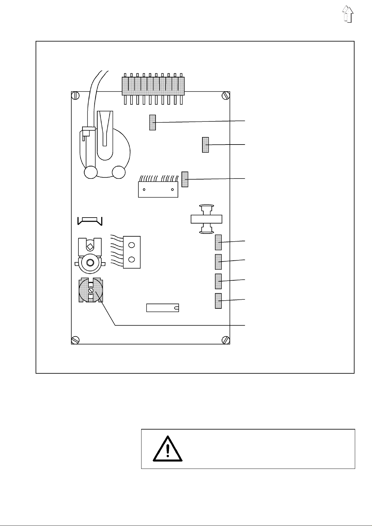
Control board (200-3):
EPROMS
Safety bridg e
Storage battery
39
 Loading...