


Contents Page:
Home
Part 3: Service manual, cla ss 271 - 275
1. General
1.1 Gauges . . . . . . . . . . . . . . . . . . . . . . . . . . . . . . . . . . . . . . . . . . . . . . . . . 4
1.2 Description and adjustment of the integral adjusting disc . . . . . . . . . . . . . . . . . . . . . 5
1.3 Positioning the integral adjusting disc with respect to the arm shaft . . . . . . . . . . . . . . . 6
2. Null point, feed with fitments
2.1 Null-point adjustment (position of stitch-length regulator) . . . . . . . . . . . . . . . . . . . . . 7
2.2 Feed halt when the stitch-length regulator (thrust cam) moves . . . . . . . . . . . . . . . . . . 8
2.3 Lift cam and feed-dog height . . . . . . . . . . . . . . . . . . . . . . . . . . . . . . . . . . . . . 9
2.3.1 Eccentric bush . . . . . . . . . . . . . . . . . . . . . . . . . . . . . . . . . . . . . . . . . . . . . 11
2.4
2.5
2.6
2.7
2.7.1 Synchronisation of underfeed and roller overfeed . . . . . . . . . . . . . . . . . . . . . . . . . 16
2.7.2 Distance between feed roller and needle . . . . . . . . . . . . . . . . . . . . . . . . . . . . . . 17
2.7.3 Feed-roller lift . . . . . . . . . . . . . . . . . . . . . . . . . . . . . . . . . . . . . . . . . . . . . 18
2.7.4 Roller pressure . . . . . . . . . . . . . . . . . . . . . . . . . . . . . . . . . . . . . . . . . . . . . 19
2.7.5 Fabric deflector . . . . . . . . . . . . . . . . . . . . . . . . . . . . . . . . . . . . . . . . . . . . 19
2.7.6 Roller-overfeed belt tension . . . . . . . . . . . . . . . . . . . . . . . . . . . . . . . . . . . . . 20
2.7.7 Replacing the feed roller . . . . . . . . . . . . . . . . . . . . . . . . . . . . . . . . . . . . . . . 21
Class 272/27 4:
Class 272/27 4:
Class 272/27 4:
Class 273/27 4:
. . . . . . . . . . . . . . . . . . . . . . . . . . . . . . . . . . . . . . . . . . . . . . . . . 3
synchronisation of needle feed and underfeed . . . . . . . . . . . . . . . . . 12
distance between needle bar and pressure bar . . . . . . . . . . . . . . . . . 13
aligning the feed dog . . . . . . . . . . . . . . . . . . . . . . . . . . . . . . . . 14
roller overfeed . . . . . . . . . . . . . . . . . . . . . . . . . . . . . . . . . . . 15
3. Foot height and lift
3.1 Pressure-bar height . . . . . . . . . . . . . . . . . . . . . . . . . . . . . . . . . . . . . . . . . . 22
3.2 Mechanical foot lift . . . . . . . . . . . . . . . . . . . . . . . . . . . . . . . . . . . . . . . . . . 23
3.3 Electromagnetic foot lift . . . . . . . . . . . . . . . . . . . . . . . . . . . . . . . . . . . . . . . . 24
3.4 Hinged foot . . . . . . . . . . . . . . . . . . . . . . . . . . . . . . . . . . . . . . . . . . . . . . . 25
3.4.1 Compensating hinged foot . . . . . . . . . . . . . . . . . . . . . . . . . . . . . . . . . . . . . . 26
4. Upper-thread tensioner release
4.1 Thread take-up spring . . . . . . . . . . . . . . . . . . . . . . . . . . . . . . . . . . . . . . . . . 28
5. Bobbin winder
6. Needle-bar height
7. Shuttle adjustments
7.1 Loop lift and distance between shuttle beak and needle . . . . . . . . . . . . . . . . . . . . . . 31
7.2 Shuttle-drive housing . . . . . . . . . . . . . . . . . . . . . . . . . . . . . . . . . . . . . . . . . 32
7.3 Bobbin-housing holder . . . . . . . . . . . . . . . . . . . . . . . . . . . . . . . . . . . . . . . . 33
. . . . . . . . . . . . . . . . . . . . . . . . . . . . . . . . . . . . . . . . . . . . 29
. . . . . . . . . . . . . . . . . . . . . . . . . . . . . . . . . . . . . . . . . . 30
. . . . . . . . . . . . . . . . . . . . . . . . . . . . . . . . . . . . . . . . . 31
. . . . . . . . . . . . . . . . . . . . . . . . . . . . . . . . . . 27

Contents Page:
8. Thread clipper
8.1 Control cam for timing the blade movement . . . . . . . . . . . . . . . . . . . . . . . . . . . . 34
8.2 Positioning the fixed blade . . . . . . . . . . . . . . . . . . . . . . . . . . . . . . . . . . . . . . 35
8.3 Sharpening the fixed blade . . . . . . . . . . . . . . . . . . . . . . . . . . . . . . . . . . . . . 36
8.4 Thread-guide plate, adjusting plate . . . . . . . . . . . . . . . . . . . . . . . . . . . . . . . . . 37
8.5 Hooked blade . . . . . . . . . . . . . . . . . . . . . . . . . . . . . . . . . . . . . . . . . . . . . 38
8.6 Cutting pressure . . . . . . . . . . . . . . . . . . . . . . . . . . . . . . . . . . . . . . . . . . . 40
9. Class 271/272: thread retractor
10. Class 272: edge cutter
10.1 Replacing the sewing equipment . . . . . . . . . . . . . . . . . . . . . . . . . . . . . . . . . . 44
10.2 Adjusting the indicator bracket . . . . . . . . . . . . . . . . . . . . . . . . . . . . . . . . . . . 45
10.3 Sharpening or replacing the blades . . . . . . . . . . . . . . . . . . . . . . . . . . . . . . . . . 46
11. Class 271: cross-cutter
12. Class 275: differential foot overfeed
12.1 Adjusting the overfeed-foot travel . . . . . . . . . . . . . . . . . . . . . . . . . . . . . . . . . . 50
12.1.1 Synchronisation of overfeed foot and feed dog . . . . . . . . . . . . . . . . . . . . . . . . . . 51
12.2 Adjusting the overfeed-foot lift . . . . . . . . . . . . . . . . . . . . . . . . . . . . . . . . . . . 52
12.2.1 Adjusting the overfeed-foot eccentric . . . . . . . . . . . . . . . . . . . . . . . . . . . . . . . . 52
12.2.2 Adjusting the overfeed lift height . . . . . . . . . . . . . . . . . . . . . . . . . . . . . . . . . . 53
12.2.3 Position of the overfeed foot . . . . . . . . . . . . . . . . . . . . . . . . . . . . . . . . . . . . . 54
12.3 Adjustment of the extra-thickness operating lever . . . . . . . . . . . . . . . . . . . . . . . . 55
. . . . . . . . . . . . . . . . . . . . . . . . . . . . . . . . . . . . . . . . . . . . 34
. . . . . . . . . . . . . . . . . . . . . . . . . . . . . . . . . 41
. . . . . . . . . . . . . . . . . . . . . . . . . . . . . . . . . . . . . . . 42
. . . . . . . . . . . . . . . . . . . . . . . . . . . . . . . . . . . . . . 47
. . . . . . . . . . . . . . . . . . . . . . . . . . . . . . 50
13. Replacing the arm-shaft bearing
14. Lubrication
14.1 Oil circulation . . . . . . . . . . . . . . . . . . . . . . . . . . . . . . . . . . . . . . . . . . . . . 58
14.2 Shuttle lubrication . . . . . . . . . . . . . . . . . . . . . . . . . . . . . . . . . . . . . . . . . . 59
15. Control and operating panel
15.1 Control and QUICK operating panel . . . . . . . . . . . . . . . . . . . . . . . . . . . . . . . . 60
15.1.1 Changing settings . . . . . . . . . . . . . . . . . . . . . . . . . . . . . . . . . . . . . . . . . . 60
15.1.2 RESET . . . . . . . . . . . . . . . . . . . . . . . . . . . . . . . . . . . . . . . . . . . . . . . . . 61
15.2 Control and EFKA operating panel . . . . . . . . . . . . . . . . . . . . . . . . . . . . . . . . . 62
15.2.1 Changing settings . . . . . . . . . . . . . . . . . . . . . . . . . . . . . . . . . . . . . . . . . . 62
15.2.2 RESET . . . . . . . . . . . . . . . . . . . . . . . . . . . . . . . . . . . . . . . . . . . . . . . . . 63
16. Maintenance
17. Summary of all sewing-machine settings
. . . . . . . . . . . . . . . . . . . . . . . . . . . . . . . . . . . . . . . . . . . . . . 57
. . . . . . . . . . . . . . . . . . . . . . . . . . . . . . . . . . . . . . . . . . . . . 64
IMPORTANT
The illustrations in this manual are of various classes or sub-classes
of the special sewing machine.
Please remember that your special sewing machine may differ from
the machine illustrated.
. . . . . . . . . . . . . . . . . . . . . . . . . . . . . . . . . 56
. . . . . . . . . . . . . . . . . . . . . . . . . . . . . . . . . . . . 60
. . . . . . . . . . . . . . . . . . . . . . . . . . . . 65
1. General
This service manual describes the adjustment of the special sewing
machine, classes
271 to 275
.
271
272
273
274
275
IMPORTANT
The processe s de s cr i be d i n th i s ma nu al m ay o nl y b e c a rr i ed ou t b y
specialist personnel or persons with appropriate training.
Caution: danger of injury
Before all repair, conversion and maintenance work turn off the main
switch and isolate the machine from the pneumatic supply.
When carrying out adjustment work and function-testing with the
machine runn i ng , c o mp l y wi t h a l l s af et y me as u res a nd ta k e t he utmost
care.
single-needle double-lockstitch machine
with skipp i ng un de r fe ed
single-needle double-lockstitch machine
with skipp i ng un de r fe ed an d n ee dl e fe ed
single-needle double-lockstitch machine
with skipp i ng un de r fe ed an d i n te r mittent roller ov e r fe ed
single-needle double-lockstitch machine
with skipp i ng un de r fe ed , n ee dl e fe ed an d
intermittent roller overfeed.
single-needle double-lockstitch machine
with skipp i ng un de r fe ed an d d i ffer en ti a l fo ot ov e rfe ed
This service manual describes the adjustment of the sewing machine
in a logical o rde r. It must b e b orne in mind that v a r iou s ad j us t me nt s
are mutually dependent. The adjustment process must therefore be
carried out in the order given.
For all adjus t me nt s of s ti t c h-forming components a flawles s n ew
needle must be fitted.
When adjusting cutting devices the tools must be replaced.
IMPORTANT
All colour- m ark e d c o mp on en ts a r e f ac t ory - se t. These settings sh ou l d
not be altered ex c e pt by specialists.
3

1.1 Gauges
1 2 3
4 5 6
With the ad j ust ment gauges listed below the se wi n g m ac h i ne c an be
precisely ad j us t ed an d t es t ed .
item g auge order no. u se
1
2
3
4
5
6
gauge 0216 001069 needle-bar height clas s 27 1/ 27 3
gauge 0272 001240 needle-bar height clas s 27 2/ 27 4
adjusting pi n 9 30 1 0 22 60 8 lock sewing machine in positions A -
gauge 0271 000767 needle-bar height and shuttle-drive housing
with small shuttle ( 0271 000751 / 0271 001991 )
gauge 0271 000766 needle-bar height and shuttle-drive housing
with large s h ut tl e ( 02 71 00 10 21 / 0 27 1 0 02 041 )
gauge Z124 000443 a dj u sti n g e dge cutter clas s 27 2
F
4

1.2 Description and adjustment of the integral adjusting disc
3 4
1
2
3
The sewing ma c hi n e c a n b e l o ck ed i n a l l ad j ustment positio ns w i th
locking pin 3 and the integral adjusting disc 4 on the synchronous-belt
pulley of the arm shaft.
The adjusting disc has 6 notches which are marked on the handwheel
by the letters A, B, C, D, E and F. In conjunc ti o n with marking 2 t he
letters indicate the position of the notches in which the machine can
be locked wi th pi n 3.
Notch A (loop-lift position) is deeper than the other notches.
A
B
E
F
D
C
The following items should be adjusted in the various positions:
A
B
C
D
E
F
adjusting disc with respect to the groove in the arm-shaft crank,
parallelism, belt wheel, loop lift, distance of shuttle beak from
needle
feed-dog standstill when stitch-length regulator moves,
classes 271 + 273
foot-overfeed standstill when upper regulator moves
class 275
(
2nd needle position
control cam for thread clipper
needle-bar height,
feed-dog standstill when stitch-length regulator moves,
classes 272 + 274
lift cam,
1st needle position
).
class 275
(feed-dog TDC)
(feed dog TDC).
.
5

1.3 Positioning the i ntegral adjusti ng disc wit h respec t to the a rm shaf t
1
2
3
4
X
IMPORTANT
Adjustments carried out with the adjusting disc will only be correct if
the disc it s el f ha s be en ad j usted as describ ed be l ow.
If the arm shaft is moved, all subsequent settings must be checked
and adjusted if necessary.
Y
Caution: danger of injury
Turn off the main switch.
The position of the arm shaft may only be adjusted with the sewing
machine switched off.
Regulation and inspection
The groove 4 an d n ot c h A of the adjust in g disc on the
synchronous - b el t pu l l ey m us t c oi n c ide on the
–
Lock the arm shaft with a loc k i ng pi n or a 5 m m Ø p i n i n th e
arm-shaft g roo v e 4 ( th rough hole 3).
–
It must be possible to pass the locking pin through the hole 2 in
position A into the integral adjusting disc.
Adjustment
–
Remove bobbin-winder cover 1.
–
Undo the screws o f s yn c hro no us -b el t pu l l ey 6 fr o m a bov e w i th th e
Allen key 5 t hro ugh the hole.
–
Lock the syn chr o no us -b el t pulley in posi ti o n A with the locking pin.
–
Insert a 5 mm- th i ck pi n i nt o t he r i g h ol e 3 a nd al l o w it to engage in
the arm-shaft groove 4.
–
Tighten the screws on th e s y n chr o no us -belt pulley 6 .
The synchro no us -b el t pulley must not be axially sh i ft ed .
X - Y
line.
6
5 6
2. Null point, feed with fitments
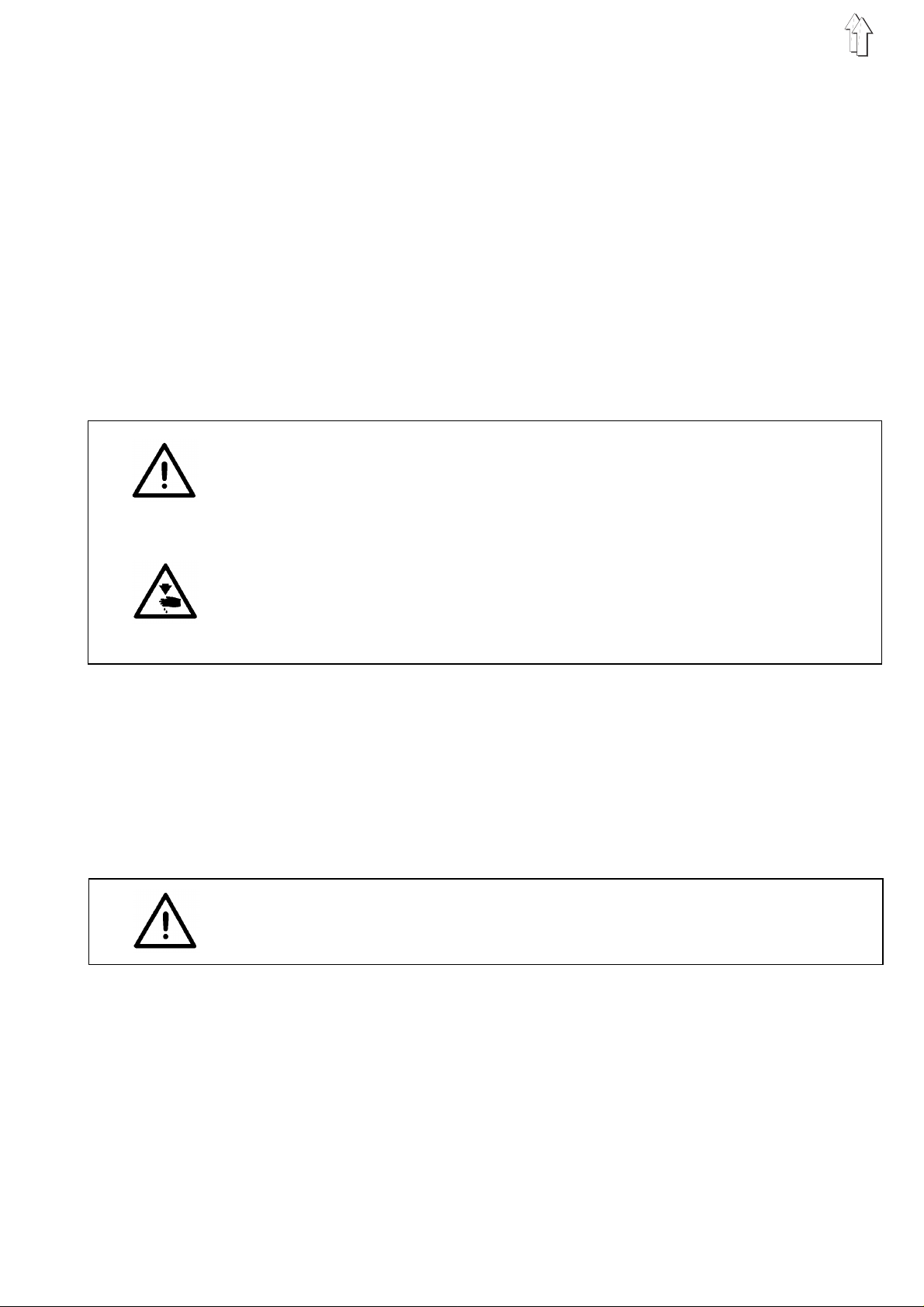
2.1 Null-point adjustment (position of stitch-length regulator)
1
2
3
4
5
Regulation and inspection
With the sti tc h - len gth lever 4 or the ad j us t i ng wh ee l s 5 in their null
positions the fe ed do g a nd ne ed l e m ust no t m ov e wh en th e h an dw he el
is turned.
Caution: danger of injury
Turn off the main swit ch.
The feed null - po si ti o n m us t on l y be ad j usted with the ma chi n e
switched off.
Adjustment
–
Set the stitch-length lever 4 or adjusting wheels 5 to "0".
–
Undo screw 3.
–
Insert screwdriver into hole 1.
–
Rotate guide 2.
The feed must not operate when the handwheel is turned.
To increase the forward feed: turn in the + arrow directio n
To decrease the forward feed: turn in the - arrow direction
–
Retighten s cr e w 3 .
7

2.2 Feed halt when the sti tch-lengt h regulator (thrust ca m) moves
1
2
Regulation and inspection
With the sewing machine locked in position B (
position E (
must be no feed movement when the stitch-length regulator 2 is
moved.
class 272/274
) and the stit c h l e ng th at ma x i mu m, th er e
class 271/27 3/ 27 5
) or
Caution: danger of injury
Turn off the main switch.
The feed standstill may only be adjusted with the sewing machine
switched off.
Adjustment
–
Set the stitch length to maximum.
–
Undo both screw s of th r ust c am 1.
–
Lock sewing ma c hi n e:
class 271/27 3/ 27 5
class 272/274
–
Rotate thrust cam 1.
When the st itc h - l en gt h regulator 2 is mo v ed th e f eed dog must
remain at a halt.
–
Retighten both screws of thrust cam 1.
This must place the thrust cam 1 hard up against the bearing
(axial shaft position).
in position
in position
B
E
.
8

2.3 Hub cam and feed-dog height
1
2
3
4
6
7
5
Regulation and inspection
With the sewing machine locked in position B (
position E (
connecting rod 8 must be in line.
In its highes t po s i ti o n t he fe ed do g s h ou l d p r ot rud e b y 0. 9 o r 1. 1 m m i n
the region of t he needle hole:
Caution: danger of injury
Turn off the main swit ch.
The lift cam and feed-dog height may only be adjusted with the sewing
machine turn ed off.
Lift-cam adjustment
–
Undo both screws of the lift cam 7.
–
Lock the sewing machine:
class 271/273/275:
class 272/274
–
Rotate lift cam 7.
The markings 3 and 6 must be in line.
–
Retighten both screws of lift cam 7.
class 272/274
0.9 mm with a fine-toothed feed dog
1.1 mm with a coarse-toothed feed dog.
: in position E.
) markings 3 an d 6 of the lift cam 7 an d t he
in position
B
class 271/273/275
8
) or
Feed-dog height adjustment
–
Lock the sewing machine:
class 271/273/275
class 272/274
–
Undo screw 1.
–
Rotate eccentric bolt 2.
In its highes t po s i ti o n t he fe ed do g s h ou l d p r ot rud e b y 0. 9 o r
1.1 mm in the re gi o n o f the needle hole :
0.9 mm with a fine-toothed feed dog
1.1 mm with a coarse-toothed feed dog.
The position of the eccentric bolt 2 depends on the adjustment of
eccentric bush 4 in the advance lever 5. See section 2.3.1.
–
Retighten s cr e w 1 .
: in position
: in position E.
B
9

1
Fig.: A
2
1
Fig.: B
2
1
Fig.: C
2
1
2
Fig.: D
10
2.3.1 Eccent ri c b us h
Regulation and inspection
Class 271/273/275
The eccentri c bu s h 1 i s ad j us t ed at the factory so th at at
dog is paral lel t o t he ne ed l e- p lat e s u r fa ce. In th e b as i c p os i t i on th e sl i t
is horizontal
When the feed do g e me r ge s fro m t he needle plate it s ba c k en d
emerges firs t.
When the slit of the eccentric bush is in the
feed dog emerges from the need l e p l at e i n para l l el . Thi s av oi d s
stretching the material. This is particularly important with stretch
material or ma te ri al w hi ch i s ine l as t ic i n t he wa rp a nd we ft di re c ti o ns
but which stretches when sewn in the diagonal direction.
When the slit of the eccentric bush is in the up position, t he feed dog
is at a greate r an gle
This angled emergence improves "smooth sewing" with inelastic
material su ch a s po pl i n an d c e rt a in l i n i ng ma te r i als . If necessary th e
eccentric bush can also be placed in intermediate positions.
Class 272/274
The eccentri c bu s h 1 i s ad j us t ed at the factory so th at at
dog has a sli gh tl y r e arwards slope. In th e b as i c p os i t i on th e sl i t i s at an
angle of 45° to the horizo nt al
(Fig. A)
.
(Fig. C)
down
position
when it emerges from the needle plate.
(Fig. D)
.
TDC
(Fig. B)
TDC
the feed
, the
the feed
IMPORTANT
If the eccentr i c b ush has been altere d, th e f ee d- d og he i gh t m us t be
re-adjusted (see section 2.3).
Caution: danger of injury
Turn off the main swit ch.
The eccentric bush may only be adjusted with the sewing machine
switched off.
Adjustment
–
Undo screw 2.
–
Adjust eccentric bush 1.
–
Retighten s cr e w 2 .
11
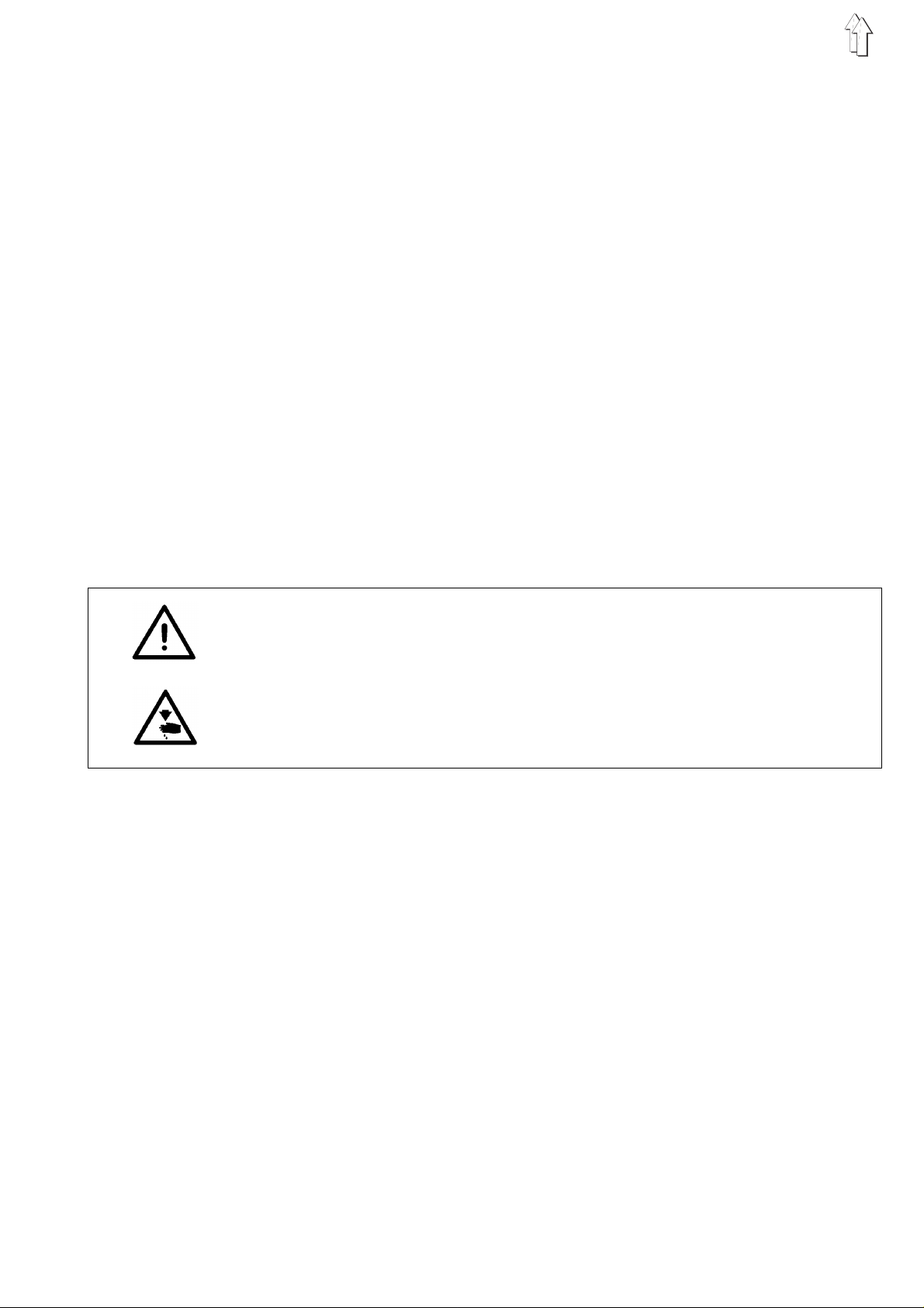
2.4 Class 272/274: synchronisation of needle feed and underfeed
1 2 3 4
Regulation and inspection
The needle fe ed an d underfeed are f actory-set to be e qu al .
–
Set stitch l e ng th to ma x i mu m.
–
Check synchro ni sa ti o n b y tu rni n g t he ha nd wh ee l.
5 6 7 8
Caution: danger of injury
Turn off the main switch.
The needle feed and underfeed may only be adjusted with the sewing
machine switched off.
Adjustment
–
Remove bobbin-winder cover.
–
Check that groove 4 of shaft 1 and slit 2 of block 3 are in line.
If not, turn shaft 1 until they are.
–
Undo locking screw 8.
–
1
6
8
Turn eccentric bolt 6.
Groove 5 and slit 7 must be in the position shown in the illustration.
The synchro ni s a tion of needle feed and underfeed is se t.
–
Retighten locking screw 8.
With feed-critical material, in order to reduce any displacement of the
fabric layers which may occur, the needle feed can be set up to some
15% greater than the underfeed by turning eccentric bolt 6.
Turning it by 180° produces the maximum adjustment.
The distanc e be tw ee n t he needle bar and pre s s ure bar remains at
9 mm during th i s ad j ustment.
If the eccentric bolt is adjusted by less than this, the distance between
the needle bar and pressure bar must be re-adjusted.
12
IMPORTANT
When the nee dl e fe ed i s i nc r e ase d the needle must no t t ouch the
sides of the needle hole in the feed dog.
2.5 Class 272/27 4: dista nce betw een needle bar and pres sure bar
2
1
9 mm
Regulation and inspection
When the stitch regulator is at "0", the distance between the needle
bar and pressu r e b ar sh ou l d b e 9 mm.
Caution: danger of injury
Turn off the main swit ch.
The distance may only be adjusted with the sewing machine switched
off.
Adjustment
–
Set the stitch regulator to " 0 ".
–
Undo locking screw 2.
–
Swivel the ne edle-bar guide.
Use gauge 1 to ad j ust the distance be tw ee n t he needle bar and
pressure bar to 9 m m.
gauge 1 order no.: 02 71 00 07 67
–
Tighten locking screw 2.
13

2.6 Class 272/274 : aligni ng the feed dog
1
2
Regulation and inspection
The needle should enter the centre of the feed-dog needle hole if the
distance be tween the needle b ar a nd pr e s sur e ba r is c orr e c tl y s e t t o
9 mm.
Caution: danger of injury
Turn off the main switch.
The feed dog ma y on l y be ad j us t ed wi t h t he s ew i ng ma c hi n e s w i tc h ed
off.
Adjustment
–
Undo locking screw 2 of the advance lever 1.
–
Align feed do g.
The needle should enter the centre of the feed-dog needle hole.
The distance between the feed dog and the needle plate should be
equally large at each side.
–
Retighten locking screw 2.
14

2.7 Class 273/ 274: r oller overfe ed
1
4
5
2
3
6
Regulation and inspection
The feed roller 3 is automatically lifted when the sewing foot is raised
and for bar-tacking.
This function must be entered in control field 5.
See setting-up instructions, section 12.
The maximum f ee d l e ng th of th e i n te r mi t te nt r ol ler overfeed is 7 m m.
The feed length can be adjusted independently of the underfeed with
adjusting wheel 4.
With the basi c stitch length a t 4 mm th e threaded pin 6 l im i ts t he
maximum rol ler - o ver f ee d f ee d l e ng th to 5 mm.
1 = lever raises the feed roller
2 = button automatically lowers feed roller
the functi on is en te r ed at th e c o nt r ol f i eld
Caution: danger of injury
Turn off the main swit ch.
The feed length may only be adjusted with the sewing machine
switched off.
Adjusting the maximum feed length
–
Remove threaded pin 6.
The maximum f ee d l e ng th i s i ncr e as e d t o 7 mm .
IMPORTANT
Account must be taken of the machine’s basic sewing equipment.
Adjusting the raising and lowering function
–
Set the des ir ed fu nc t i on at th e c o nt r ol f i eld .
(See setting-up instructions, section 12).
15

2.7.1 Synchronisation of underfeed and roller overfeed
4
Caution: danger of injury
Turn off the main switch.
Synchronisation may only be adjusted with the sewing machine
switched off.
34
12
Regulation and inspection
The operation of the underfeed and roller overfeed should be
synchronised.
On no account may the movement of the overfeed roller be completed
before that of the feed dog.
This ensure s th at th e m at er i a l be tw ee n t he sewing foot an d the roller
remains under tension, thus minimising seam-crimping when the
stitches a re tightened.
–
Remove bobbin-winder cover.
–
Lock the sewing machine:
class 273:
class 274
–
The groove 4 o f t he c am 2 a nd th e g r oo v e 3 of th e c o nn ec t i ng rod
1 must coincide.
Adjustment
–
Remove locki ng pin .
–
Undo fastening screws of cam 2.
It should be possible to rotate the cam on the shaft with minimum
effort.
–
Secure cam 2 with a screwdriver.
–
Turn handwheel:
class 273:
class 274:
–
Retighten fastening screws of the cam 2.
–
Check that groove 4 of the cam and groove 3 of the connecting rod
coincide.
If not, the ad j us t me nt must be repeated .
–
Replace bobbin-winder cover.
: in position
in position
to position
to position
B
E.
B
E.
16

2.7.2 Distance between feed roller and needle
1
2
28,5 mm
Regulation and inspection
The distance between the centre of the roller and that of the needle is
28.5 mm.
Where a compensating hinged foot is fitted the distance is 30 mm.
IMPORTANT
When the distance is reset the upper and lower end positions must
also be re-adj u s te d ( se e s e c ti o n 2 .7 .3 ) .
Caution: danger of injury
Turn off the main swit ch.
The distance may only be adjusted with the sewing machine switched
off.
Adjustment
–
Undo screw 1.
–
Turn link 2 on the axle.
The distanc e b et we en th e c e nt r es o f t he r ol le r an d t he ne edle must
be 28.5 or 30 mm.
–
Retighten s cr e w 1 .
17

2.7.3 Feed-roller lift
1
2
3
4
5
Regulation and inspection
In the
sewing foot.
In the
needle plate, the link 1 must encounter elastic resistance about 1 mm
before the hand-lever stop reaches its limit position.
If a
position. T h e s t ee l rol l e r must not make co nt ac t wi t h th e ne ed l e pl a te ,
which it would damage.
upper end position
lower end position
steel roller
is used there must still be a gap in the lower end
the lifted f ee d ro l l er m ust not touch the
, after the roller has been placed on the
Caution: danger of injury
Turn off the main switch.
The lift may only be adjusted with the sewing machine switched off.
Adjusting the upper end position
–
Rotate bolt 2.
The slit of the bolt must be parallel to the cylinder axle.
–
6
7
Limit the stroke of cylinder 3.
Use a 2.5 mm A l len key to adjust the thre ad ed pi n 7 ac c o rdi n gl y.
6 = access to threaded pin 7
2
Adjusting the lower end position
–
Undo locknut 4.
–
Screw threaded pin 5:
in: to raise
out: to lower.
–
Retighten locknut 4.
18

2.7.4 Roller pre ssure
1
2
3
4
Regulation and inspection
The feed-roller pressure must be suitable for the material being sewn.
2.7.5 Fabric deflector
IMPORTANT
If the pressure has been altered the upper end position must be
re-adjusted (see section 2.7.3).
Caution: danger of injury
Turn off the main swit ch.
The roller pressure may onl y be ad j ust ed with the sewi ng ma c hi n e
switched off.
Adjustment
–
Undo screw 2.
–
Move cylinder 1:
in the direction of arrow
in the direction of arrow
–
Retighten s cr e w 2 .
Regulation and inspection
The function of th e f abric deflecto r 3 i s t o p r ev e nt th e m at er i a l fr o m
getting int o t he ga p. T he pre s s ure of the fabric de fl e cto r on th e r oll e r
should be such that the roller can only just rotate freely. If a steel roller
is fitted, the fabric deflector must be removed.
A:
B:
to reduce pressure
to increase pressure.
Caution: danger of injury
Turn off the main swit ch.
The fabric deflector may only be adjusted with the sewing machine
switched off.
Adjustment
–
Undo screw 4.
–
Adjust fabric deflector 3.
–
Retighten s cr e w 4 .
19

2.7.6 Roller-overfeed belt tension
1
23
4 5 6
Regulation and inspection
The tension in the synchronous belts should so be such that the step
lengths are precisely tran smi t te d.
Excessiv e b el t te ns i o n can cause heavy wear and malfun c ti o ns.
Caution: danger of injury
Turn off the main switch.
The upper and lower belt tension may only be adjusted with the
machine turned off.
Adjusting the upper synchronous belt
–
Undo screw 2.
–
Move lever 3.
Adjust the t ension of the syn c hr o no us b el t 1 a s req ui r e d.
–
Retighten screw 2.
Adjusting the lower synchronous belt
–
Undo screw 6.
–
Move lever 5.
Adjust the t ension of the syn c hr o no us b el t 4.
–
Retighten screw 6.
20

2.7.7 Replacing the feed roller
1 2 3
45678
IMPORTANT
If a Vulkollan roller is replaced by a steel roller or vice versa, the lower
end position mu s t b e r e -adjusted (see s ec t i on 2. 7. 3) .
If a steel rol l e r i s fi t te d, th e f abric deflecto r must be removed.
If the 15mm-wide rubber roller is being used, the broad fabric deflector
(order no.: 0273 000620) must be fitted.
Caution: danger of injury
Turn off the main swit ch.
The feed roller must be repla c ed wi t h t he s ew i ng ma c hi n e s w i tc h ed off.
Replacing the roller
–
Remove nut 1.
IMPORTANT: this nut has a left-handed thread.
Lock axle 3 a t t he ot he r en d w i th a s c re w d ri v er.
–
Replace fe ed rol l e r 2.
–
Replace nut 1.
item order no.: description
4 0933 005763 steel roller 9 mm
5 0933 005737 steel roller 15 mm
6 0933 005738 a steel roller 15 mm, 2 mm saw-tooth
7 0933 005737 a rubber rolle r 15 mm
8 0933 005725 Vulkollan roller 9 mm
21

3. Foot height and lift
3.1 Pressure-bar height
The maximum s ew i ng -f o ot l if t i s 12 mm for machines wi th ou t a thread
clipper an d 7 mm fo r machines with a t hre ad clipper.
1
2
2
0,5 mm
3
Regulation and inspection
Class 271/27 3/275
When the sol e o f the foot is in c o nt ac t wi t h t he ne ed l e p l at e t he r e
should be a di s t an c e o f 0 .5 mm between the blo ck 1 a nd th e traction
bracket 3.
Class 272/27 4
When the sol e o f the foot is in c o nt ac t wi t h t he ne ed l e p l at e t he r e
should be a di s t an c e o f 0 .5 mm between the blo ck 1 a nd th e b us h 4.
0,5 mm
5
4
22
Caution: danger of injury
Turn off the main switch.
The height of the pressure bar may only be adjusted with the sewing
machine switched off.
Adjustment
–
Remove cover.
–
Undo screw 2.
–
Adjust the pressure-bar height.
The distance should be 0.5 mm as described above.
–
Align the sewi n g f oo t s o th at th e n ee dle en te r s th e c e nt re o f t he
sewing-foot needle hole and retighten screw 2.
–
Replace cover.

3.2 Mechanical foot lift
1
2
Regulation and inspection
With the sewing foot in contact with the needle plate a small amount of
free movement must be perceptible in the knee lever.
Caution: danger of injury
Turn off the main swit ch.
The knee lever may only be adjusted with the sewing machine
switched off.
3
4
Adjustment
–
Undo nut 4.
–
Adjust the maximum lift with stop screw 3.
–
Retighten n ut 4.
–
Undo nut 2.
–
Adjust screw 1.
With the sewing foot in contact with the needle plate a small
amount of fre e m ovement must be per c e pt i bl e in the knee lever.
–
Retighten n ut 2.
23

3.3 Electromagnetic foot lift
1 2 3 4
Regulation and inspection
The armature of the lifting ma gn et must reach its l e ft - ha nd en d
position wh en it i s o pe rat ed .
After seve ral y e ars ’ inte nsi v e us e th e d i me ns i o ns o f t he da mp i ng di sc
6 may change, as a result of which the lowering of the sewing foot
becomes too slow or the magnet makes knocking noises when it
operates. This can mean that when started up the sewing machine
executes a f ew stitches before the foot has fu l l y r ea c he d t he ma te r i al
(i.e. there i s a danger of fault y st itches at the st art of the seam).
Caution: danger of injury
Turn off the main switch.
The sewing-foot lift may only be adjusted with the sewing machine
switched off.
Adjustment
–
Undo nut 2 and sc re w 1 .
–
Set the required lift with the articulated lever 3.
The armature of the lifting ma gn et 4 must reach it s l ef t- h an d e nd
position.
–
Retighten screw 1 and nut 2.
5 6
24
–
Remove retaini n g w as h er 5 .
–
Remove the li fting magnet fro m i t s ho usi n g.
–
Replace damping disc 6 (0271 001767).
–
Replace lifting magnet.
–
Replace retai ni n g w ash er 5 .
7
IMPORTANT
In case of the classes
min. 0,5 mm
8
change of th e l ift
position, the minimum distance between the hinged foot top 8 and the
fabric bar bush 7
Otherwise, the parts of the lifting system may be damaged.
it is absolutely necessary to ensure
amounts to 0.5 mm
273
and
please note that following a
274
.
that, in lifting

3.4 Hinged foot
1
2
3
Regulation and inspection
With the hing ed foot the height of the pressure b ar sh ou l d b e s u c h t ha t
when the foot is l o we red th e s o le o f t he fo ot ex e c ut es o nl y a sma l l fe ed
movement on the needle plate before the block makes contact with the
pressure bar (s ee pa ge 22 ) .
This ensures that only the sprung sole exerts slight pressure on the
material.
Caution: danger of injury
Turn off the main swit ch.
The hinged foot may only be adjusted with the sewing machine
switched off.
Adjustment
–
Adjust the pressure bar (see section 3.1).
–
Undo the screw on the back of the bolt 1.
–
Adjust bolt 1.
The torsion spring 2 determines the pressure exerted by the sole
of the foot 3.
The resilience of the spring should be adjusted with bolt 1 so that
the fabric layers are sewn together with stitches of equal length,
and without bei n g s h ifted with respect t o e ac h ot he r.
–
Retighten t he s c rew on the back of t he bo l t 1 .
25

3.4.1 Compensating hinged foot
1
2
3
4
5
6
Regulation and inspection
With the compensating hinged foot the pressure exerted by the sole of
the foot is altered by replacing the pressure springs 5.
Two pa irs of springs of different strengths are supplied with each foot.
To alter the backstitch width to the left or right of the needle only the
sole of the fo ot ne ed s to be replaced.
Caution: danger of injury
Turn off the main switch.
Foot pressur e ma y on l y be adjusted wit h t he s ew i ng ma c hi n e s w i tc h ed
off.
Adjustment
–
Remove nut 4 wi th s cr ew.
–
Insert extrac t or t oo l 3 i n th e h ol e 6.
–
Prise off the s ole of the foot.
–
Fit new sole to alter the backstitch w idth. Replace springs.
–
Replace sole of the fo ot.
–
Replace nut 4 w i th sc r ew.
–
Undo screw 1.
–
Align the sewi n g f oo t s o th at th e n ee dle en te r s th e c e nt re o f t he
sewing-foot needle hole.
–
Retighten screw 1.
IMPORTANT
In the raise d p os i t i on th ere must be a smal l ga p (a bo ut 0.5 mm)
between the block 2 of the compensating hinged foot and the
fabric-rod bush.
26

4. Upper-thread tensioner release
1
2
3
Regulation and inspection
Pressing on the axle 3 opens the tensioner by about 1 mm.
Caution: danger of injury
Turn off the main swit ch.
The upper-thread tensioner release may only be adjusted with the
sewing machi n e s w i tc h ed off.
Adjustment
–
Undo screw 1.
–
Move magnet 2.
With the upper-thread tensioner fully closed and with no thread
between the tension discs the axle 3 should have play of about
0.3 mm.
–
Retighten s cr e w 1 .
27

4.1 Thread take-up spring
3
1
2
4
5
Regulation and inspection
The thread ta k e-u p s p r i ng 1 should keep the u pp er t hre ad under
tension at least until th e tip of the needle has penetrated the material.
Caution: danger of injury
Turn off the main switch.
The thread ta k e-u p s p r i ng ma y on ly be ad j us t ed wi t h t he s ewing
machine switched off.
Adjusting the spring travel
–
Undo screw 4.
–
Rotate bush 3.
The spring 1 m us t pr e - te nsi o n t he upper thread a t least until the ti p
of the needle enters the material.
–
Retighten screw 4.
Adjusting the spring tension
–
Undo screw 5.
–
Adjust the te ns i o n v a l ue by ro ta ti n g t he tension bolt 2.
The tension of the thread-tension spring must be between 20 and
50 cN (1 cN = 1 g ) de pe nd i ng on th e m at er i a l an d t hre ad.
–
Retighten screw 5.
28

5. Bobbin winder
3
1
2
A
Regulation and inspection
The bobbin wi nd er s h ou l d a ut om at i c al ly t ur n off wh en th e b obbin is
fully wound t o a po int 0. 5 m m u nd er t he ri m.
B
Caution: danger of injury
Turn off the main swit ch.
The bobbin winder may only be adjusted with the sewing machine
switched off.
Adjustment
1. Minor adjustments to the wind-on quantity
–
Bend bobbi n-w i nd er s e nsor 3.
2. Major adjustments to the wind-on quantity
–
Remove bobbin-winder cover.
–
Undo screw 2.
–
Rotate trip cam 1:
in the direction of arrow A: to reduce th e wind-on quanti t y
in the direction of arrow B: to increas e th e w i nd - on qu an ti t y.
–
Retighten s cr e w 2 .
–
Replace bo bb i n-w i nd er c o ver.
29

6. Needle-bar height
1
2
3
4
Regulation and inspection
Classes 271/ 273/275
Adjustment and inspection a r e c a rr i ed ou t w i th ga ug es 3 an d 4 .
Caution: danger of injury
Turn off the main switch.
The needle-bar height may only be adjusted with the sewing machine
switched off.
Adjustment
–
Remove needle plate and sewing foot.
–
Undo screw 1.
–
Place gauge 4 on th e needle-plate sur f ac e .
order no.: 0271 000767 for small shuttle (0271 000751/0271 001991)
order no.: 0271 000766 for large shuttle (0271 001021/ 0271 002041)
–
Fit gauge 3 as far as it will go into the needle bar in place of a
needle.
order no.: 02 16 00 10 69 for
order no.: 02 72 00 12 40 for
and
272/274
have differing needle-bar heights.
class 271/273/275
class 272/274
30
–
Lock sewing ma c hi n e i n po si ti o n E.
The cross-head 2 is at its lowest position.
–
Push the needle ba r do wn wa rds .
The foot of t he ga ug e 3 mu s t m ak e c on ta c t w i th ga ug e 4 .
–
Retighten screw 1.
IMPORTANT
The needle-attachment screw must point to the right.
–
Replace needle plate and sewing foot.

7. Shuttle adjustments
7.1 Loop lift and distance between shuttle beak and needle
0,1 mm
2
3
1
4
Regulation and inspection
The loop lift is the travel of the needle bar from BDC to the point at
which the shu tt l e b ea k i s at th e c e nt r e o f t he ne ed l e.
The loop lift is 1.8 mm.
With the sewing machine locked in position A the shuttle beak 1
should be at the centre of the ne ed l e.
The distanc e b et we en th e s h ut tl e be ak 1 an d the needle shou l d b e
0.1 mm.
Caution: danger of injury
Turn off the main swit ch.
The loop lift and the distance between the shuttle beak and the needle
may only be ad j us t ed wi t h t he s ew i ng ma c hi n e s w i tc h ed off.
Adjustment
–
Remove sewing foot, needle plate and feed dog.
Fit new needl e.
–
Set the stitch regulator to "0".
–
Lock sewing machine in position A.
–
Undo fasten i ng s cr ew s of th e s h ut tl e 4.
The screws c an be r ea ched through hole 3.
–
Set the shuttle beak 1 to the centre of the needle.
The distanc e b et we en th e s h ut tl e be ak 1 an d the furrow of th e
needle must be 0.1 mm.
In this posi ti o n t he r e is a di s t an c e o f 0 .4 mm be tween the shutt le 4
and the adjusting ring 2.
If the dista nce of 0.4 mm is not ac h i eved, the shuttle - dri v e ho us i n g
should be adjusted accordingly (see section 7.2).
–
Retighten f as t en i ng s c rew s of th e s h ut tl e 4.
–
Replace sewing foot, needle plate and feed dog.
31

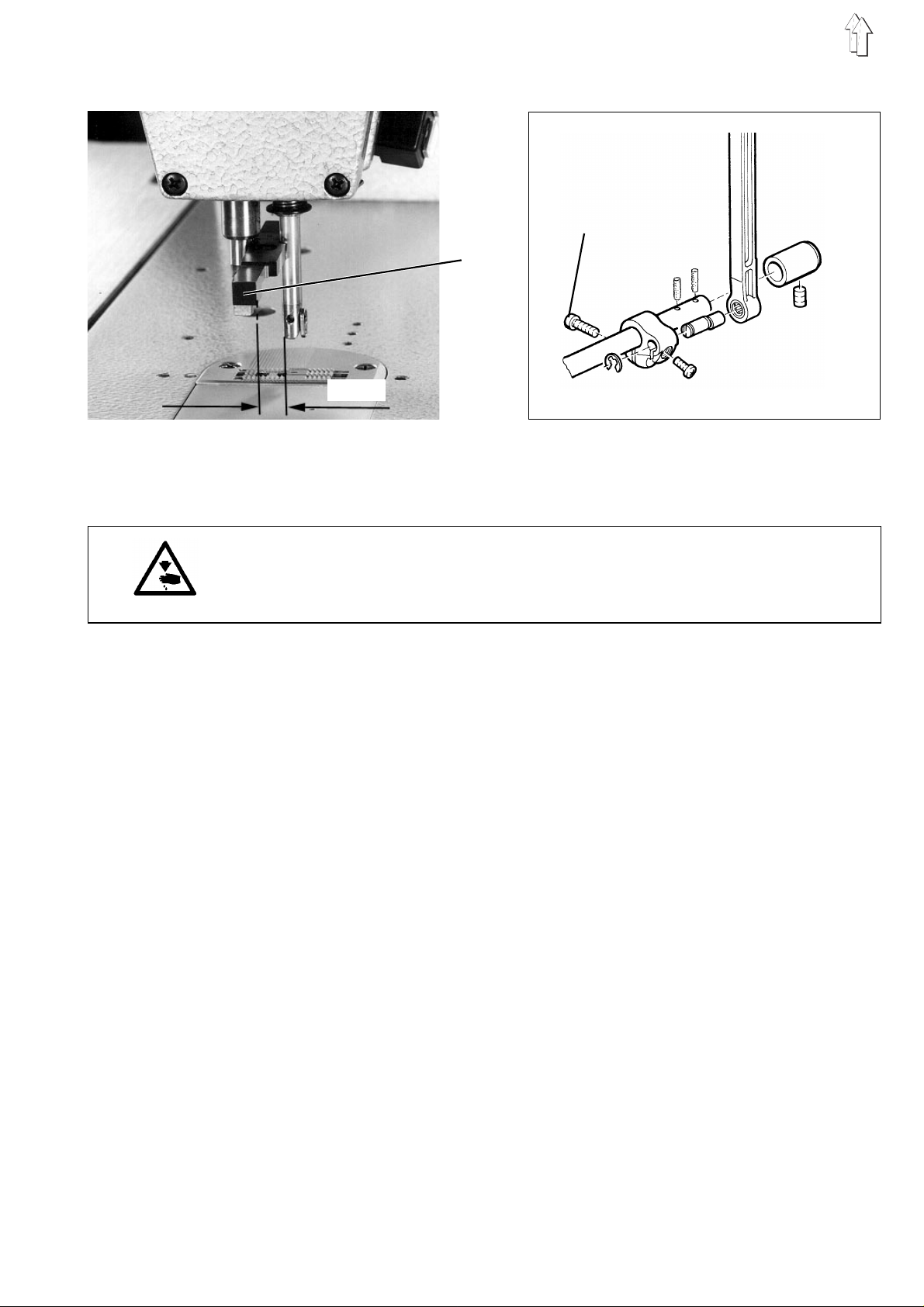
7.2 Shuttle-drive housing
1
2
3
3,3 / 3,7 mm
4
5
Caution: danger of injury
Turn off the main switch.
The shuttle-drive housing may only be adjusted with the sewing
machine switched off.
Regulation and inspection
The shuttle - dri v e ho us in g 4 is factory-al i g ne d.
It may only be altered in exceptional circumstances.
With the shuttle-drive housing correctly aligned there must be a
distance of 0.4 mm between the shuttle and the adjusting ring
(see section 7.1).
The distanc e be tw ee n t he needle-plat e su r fa c e a nd th e
thread-drawing plate 5 is:
with the sm all s h ut tl e = 3.7 mm (0271 0 00 75 1 / 02 71 00 19 91 )
with the la rge s hu tt l e = 3.3 mm (0271 0 01 02 1 / 02 71 00 20 41 )
Adjustment
–
Loosen lock i ng sc r ew 1.
Under the locking screw there is a stop screw.
–
Adjust the stop screw.
The distanc e be tw ee n t he needle-plat e su r fa c e a nd th e
thread-drawing plate 5 is:
with the sm all s h ut tl e = 3. 7 m m
with the large shuttle = 3.3 mm
The distance is checked with gauge 2.
with the small shuttle = order no.: 0271 000767
with the large shuttle = order no.: 0271 000766
–
Retighten locking screw 1.
–
Undo 2 screws 3 of th e s h ut tl e - dri v e ho us in g.
–
Move the shuttle-drive housing 4.
Between the shuttle and the adjusting ring there must be a
distance of 0.4 mm (see section 7.1).
–
Retighten screws 3 of the shuttle-drive housing.
–
Check the distance of the shuttle beak from the needle and adjust
if necessary (see section 7.1).
32

7.3 Bobbin-housing holder
1
2
3
4
Regulation and inspection
The bobbin-h ou s ing holder is facto r y- al igned.
When the holder has been replaced the new holder may need to be
re-aligned.
Caution: danger of injury
Turn off the main swit ch.
The bobbin-h ou s ing holder may only be ad j us t ed wi t h t he s ew i ng
machine swi tc h ed off.
IMPORTANT
Alignment ma y on l y be c arr i e d o ut i n t he c ros s -h atched area (see
sketch).
The extreme h ard ne s s i n t he r eg ion of the retaini n g t ab 1 m ea ns t ha t
there is a dan ge r of bre ak a ge th er e .
Adjustment
–
Align the bo bbin-housing ho l de r 4.
The distance between retaining tab 1 of the bobbin-housing holder
4 and the lowe r pa r t o f t he bobbin-housing 2 s h ou l d b e 0 .6
+0.1
mm.
33

8. Thread clipper
The control c a m 4 de termines the mo vem en t o f t he th r ea d cl i p pe r s an d
the timing of th e b l ad e m ove me nt . T h e t i min g t hu s coi nc id es wi t h th e
movement of th e s t i tch-forming comp on en ts .
The thread c l ipp er i s switched on ele c tro ma gn etically.
8.1 Control cam for timing the blade movem ent
1
2
6
3
4
4
5
5
6
Regulation and inspection
When the thread clipper is not in operation there must be a distance of
0.2 to 0.3 mm between the external diameter of the control cam 4 and
the ball-r ace 6.
With the machine locked in position D ball-race 6 must engage in the
indentation 5 of the control cam 4 when manually pressed downwards.
Caution: danger of injury
Turn off the main switch.
The control cam may only be adjusted with the sewing machine
switched off.
34
Adjustment
–
Undo fastening screws 7 of the magnet 1.
–
Move magnet 1.
The distanc e be tw ee n c o nt r ol ca m 4 and the ball- rac e 6 m us t be
0.2 - 0.3 mm.
The roller 3 must be in contact with the ram 2.
–
Retighten fastening screws 7 of the magnet 1.
–
Lock sewing ma c hi n e i n po si ti o n D.
–
Undo fastening screws of the control cam 4.
–
Turn the control ca m o n t he l ow er sh aft.
The ball-race 6 must engage in the indentation 5 of the control cam
4 when manuall y p res se d d ow nwards.
The axial p osi t i on s ho ul d be s uc h th at th e c o nt r ol c a m 4 an d r o l l er
7
6 are opposi te ea c h o th er.
–
Retighten fastening screws of the control cam 4.

8.2 Positioning the fixed blade
1
1 2
2
3
3
1
Regulation and inspection
The fixed blade 3 must lie in the direction of the arrow on the screw 1
(see sketch) .
Sharpened bl ad es m us t be al i g ne d a s de sc r i be d in section 7.3.
Caution: danger of injury
Turn off the main swit ch.
The fixed blade may only be adjusted with th e sewing machine
switched off.
Adjustment
–
Unscrew cutting-pressure screws 2.
–
Undo screw 1 from below.
–
Push blade 3 i n t he di r e c tion of the arrow a ga i nst screw 1.
–
Partiall y ti g ht en screw 1 from ab ov e .
–
Adjust the cutting pressure (see section 8.6).
–
Fully tighten screw 1 from be l ow.
35

8.3 Sharpening the fixed blade
1
2
3
6
15°
4
5
Regulation and inspection
The cutting angle of the fixed blade 6 is 15° (see sketch).
It is essen ti a l fo r s ha r pe ni n g t o b e c a rr i ed ou t w i th a f i ne - gra i ne d
whetstone.
Caution: danger of injury
Turn off the main switch.
After sharpening the blade must be replaced with the sewing machine
switched off.
IMPORTANT
Blades which have lost more than 0.5 mm of their original length
through shar p en i ng mu s t b e re pl a c ed .
Adjustment
–
Undo screws 2 a nd 3.
The pre-ten si on of th e fixed blade 6 i s r e du c ed .
–
Remove the blade 6.
–
Sharpen the blade.
The cutting an gl e of th e f i x ed bl a de i s 15 °.
–
Replace the blade.
–
Align the bl ad e s o th at th e d i s ta nc e be tw een the cutting e dg e 5
and the edge 4 of the opening in the needle plate is 38.5 mm.
IMPORTANT
When replacing a blade after sharpening it must not be
allowed to make contact with the screw 1.
–
Fully tighten screw 1.
–
Re-adjust th e a t- re s t p os i t i on of th e h oo k ed bl a de ( see section 8.5)
and the cutt i ng pre s s ure ( s ee sec t i on 8. 6) .
36

8.4 Thread-guide plate, adjusting plate
Regulation and inspection
Thread-guide pl a te 2 i s u s ed wi t h t he s ma l l shu ttle, the adjus ti n g p l at e
5 with the la rge s hu tt l e.
The thread-guide plate 2 or adjusting plate 5 must point in the
direction of the arrow on the screw 3 (see sketch).
In this position the radial distance between the thread-guide plate 2 or
adjusting pl a te 5 a nd the thread-drawi n g p l at e 4 of th e s h ut tl e mu s t b e
0.5 mm.
There must be a ra di a l di s t an c e o f 0 .3 mm be tween the thread- g ui d e
plate 2 or adjusting plate 5 and the hooked blade 1.
1 4 5 3
1
2
3
2
3
Caution: danger of injury
Turn off the main swit ch.
The thread-guide plate or adjusting plate may only be removed with
the sewing machine switched off.
IMPORTANT
When the thread-guide plate (adjusting plate) has been fitted the
distances t o t he th r ea d-drawing plate 4 a nd ho ok e d b l ad e 1 mu s t b e
checked.
Adjustment
–
Partly undo screw 3.
–
Remove threa d- g ui d e p l at e 2 or a dj u st in g plate 5 for alig nment.
–
Align thre ad - gu ide plate 2 or adj usting plate 5.
–
Replace the thread-guide plate 2 or adjusting plate 5 and secure
with screw 3.
37

8.5 Hooked blade
12
3 4
Regulation and inspection
The hooked bl a de 2 m us t l i e a ga i nst the two screw s 1 i n th e d i rec t i on
of the arrow.
With the ho oked blade in the a t- re s t p os i t i on i ts t i p 6 an d t he c ut ti n g
edge 7 of the f i x ed bl a de 5 m us t be at th e s a me l ev e l .
During the blade movement the tip 6 of the hooked blade must be
exactly be ne at h t he ti p of the triangle 3 in the thread-guide pl a te 4.
Caution: danger of injury
Turn off the main switch.
The hooked bl a de ma y on l y be ad j ust ed with the sewi ng ma c hi n e
switched off.
Adjustment
–
Manually sw i v el hooked blade 2 u pw ar d s .
–
Undo fastening screws 1 of the hooked blade.
–
Push the hook ed bl a de 2 i n th e d i r ection of the arrow against the
attachment s cr ew s 1.
–
Retighten fastening screws 1.
567
38
–
Undo screw 8.
–
Adjust the at-rest po sition of the hooked blade 2.
With the ho oked blade in its a t-r e s t p os ition its tip 6 an d t he c ut ti n g
edge 7 of the f i x ed bl a de 5 m us t be at th e s a me l ev e l .
–
Retighten screw 8.
–
Operate the ho ok e d b l ad e 2 ma nu al l y.
Check that th e t i p 6 of th e h oo ked bl a de c oin c i de s wi t h t he ti p of
the triangle 3.
–
For adjustment undo screws 1 and align the hooked blade 2.
Adjustment note
With the ho oked blade 2 prope rl y ad j us t ed i ts tip 6 moves along the
line 9 duri ng th e c u tt i ng pro c es s .
The dotted line 9 runs approximately between the centre of the needle
and the shut tl e be ak.

5 1
5 7
2 6 3 4
6
0,1 mm
8
9
2
6
3
39

8.6 Cutting pressure
1
3
4
2
5
Regulation and inspection
The thread must be reliably severed with pressure as low as possible.
Low cutting pressure minimises wear.
Two of the thickest threads used must be severed simultaneously.
Caution: danger of injury
Turn off the main switch.
The cutting pr e ss ur e ma y on ly be ad j us t ed wi t h t he s ewing machine
switched off.
Adjustment
–
Loosen the cutting-pressure screws 1.
–
Swivel the hooked blade 4 under the fixed blade 2.
The cutting ed ge 5 o f the hooked blad e m us t be un de r th e c u tt i ng
edge 3 of the fixed blade 2.
–
Set the fixed blade 2 against the hooked blade 4 by screwing in the
cutting-pressure screws 1.
–
Alternately lay the thread to be severed to the right and left.
Adjust the a pp r op r iate cutting-pre s s ure s c rew.
–
If the spring no l on ge r ret ur n s th e c u tt i ng me c ha nis m to i ts s t arting
position, the cutting pressure is too great.
Sharpen (see section 7.3) o r replace fixed bl ad e 2 .
40

9. Class 271/272: thread retractor
9 1
7
8
2
3456
If at the start of a seam the upper thread-end is supposed to be pulled
through to the underside of the material, it must not be caught between
the sewing foot and the material. The thread retractor ensures that the
upper thread-end hangs loosely from the eye of the needle.
The movement of the thread retracto rs takes place after the threads
have been sev er e d a nd be fo r e t he s ew i ng fe et ha v e be en ra is ed . T he
function can be s et at th e c o nt r ol .
The thread retractor can be switched on and off with the rocker switch
9.
Regulation and inspection
At the end of the fo rward retraction movement the lever 4 should be in
contact with the Vulkollan disc 3.
The retraction movement should be completed without hindrance.
Caution: danger of injury
Turn off the main swit ch.
The thread retra c to r ma y on ly be ad j ust ed wi t h t he s ew i ng ma chi n e
switched off.
Adjustment
–
Undo screws 7 and 8.
–
Adjust magn et 1.
At the end of the fo rward retraction movement the lever 4 should
be in contact wit h t he Vulkol l an di s c 3 .
–
Retighten s cr e ws 7 an d 8 .
–
Undo screws 2.
–
Adjust the retracto r wi re 6.
The retraction movement should be completed without hindrance.
–
Retighten screws 2.
IMPORTANT
If the thread ret r ac t or i s b ei n g u s ed to ge th er w i th th e c o mp en s at i ng
hinged foot, transmission lever 4 must be replaced by transmission
lever 5 (order no.: Z120 001841).
41

10. Class 272: edge cutter
1
5
2
6
3
4
On sewing ma c hi n es with this acce s s ory t he edge of the mat eri a l c an
be cut during the sewing process.
In sub-classes
driven. It is switched on and off by a manual lever or button.
Programmi ng th e o n-a nd-off function is de s c ri be d i n th e s e tt i ng - up
instructions, section 13.
The
272 - 740142
Regulation and inspection
The edge cutter must cut reliably with the pressure as low as possible.
Caution: danger of injury
Turn off the main switch.
The edge cutter may only be adjusted with the sewing machine
switched off.
272 - 640141
sub-class is fitted with a separate electrical drive.
and
272 - 640142
it is mechanically
42
78 9
1. Adjusting the position of the blades in the direction of sewing
–
Undo screw 11.
–
Adjust blad e h ol d er 1 0.
The point at which the blade begins to cut can be set in front of
and behind the needle.
–
Retighten screw 11.
2. Adjusting the cutting position
–
Swivel the upper blade 5 down manually with the Allen key 7
(cylinder 9 e x te nd ed ). S e c ure th e p os it i on wi t h g au ge 8.
gauge 8 order no.: Z 1 24 00 04 43
On sewing machines with a manual lever the manual lever is used
to adjust the position of the upper blade.
–
Move the uppe r bl a de 5 t o
With sub-class
separate drive motor (see arrow).
-740142
this is done wi t h t he k nur l ed sc rew on the
with the handwh ee l .
BDC

10
14
15
11
56
2
4
12
13
–
Undo screw 1.
–
Adjust block 3.
The upper blade 5 should be parallel to the lower blade 6.
IMPORTANT
When the block 3 is turned it should be constantly pressed
upwards and brought to rest against the ledge of the blade bar 15.
–
Retighten s cr e w 1 .
3. Adjusting the blade-height position
–
Remove cover.
–
Swivel the upper blade 5 down manually with the Allen key 7
(cylinder 9 extended). Secure the position with gauge 8.
On sewing mach ine s wi t h a ma nu al l e v er t he ma nu al l e ver is u s ed
to adjust the position of th e u pp er b l ad e.
–
Move the upper blade 5 to
With sub-class
separate drive motor.
–
Undo screw 14.
–
Adjust the h ei g ht of blade bar 15.
When the blade is at
same level as the lower blade.
–
Retighten s cr e w 1 4.
–
Check the b lad e position at
At
blade.
the tip of the blade should still be in contact with the lower
TDC
-740142
this is done with the knurled screw on the
BDC
with the handwheel.
BDC
the edge of th e b l ad e s h ou l d b e a t t he
.
TDC
56
4. Adjusting the cutting pressure
–
Undo thread ed pi n 4.
–
Adjust screw 2.
Move the uppe r bl a de ag ai n s t t he l ow er b l ad e.
The edge cutte r s ho ul d cut reliably wi th th e m i ni m um po s s ibl e
pressure.
–
Retighten t hr e ad ed pi n 4.
–
Use the Allen key to carry out a manual cutting test.
Re-adjust the p os i t ion an d c u tt i ng pre s sur e i f n ece s sar y.
43

10.1 Replacing the sewing equipment
4
12 3
5
8
6
9
7
Regulation and inspection
The fitments should be selected in the light of the desired sewing result.
The feed dog, slider and foot should be replaced or adjusted as required.
Caution: danger of injury
Turn off the main switch.
Fitments may only be replaced with the sewing machine switched off.
Replacing the sewing equipment (without replacing the needle
plate)
–
Remove the foot an d s li d er.
–
Remove 2 screws 7.
The centring sleeve 9 ensur e s th at th e p os i t i on of th e n ee dl e pl a te
is correct.
The screw 8 must
–
Remove needle plate 6.
–
Replace the sewing equipment.
–
Replace needle plate 6.
–
Retighten 2 screws 7.
–
Carry out a manual cutting test and if necessary re-adjust the
blade as described in section 9.
–
Replace the fo ot an d s li d er.
be undone.
not
44
Replacing the sewing equipment (with replacement of the needle
plate)
–
Remove the foot an d s li d er.
–
Remove screw 7 and screw 8 with centring sleeve 9.
–
Remove needle plate 6.
–
Undo screw 1.
–
Replace the sewing equipment.

–
Adjust the guide 4.
The guide must be adapted to the width of the needle plate (cutting
width).
–
Fit new needle plate 6.
–
Replace screw 7 and screw 8 with centring sleeve 9.
–
Align needle plate.
The feed dog sh ou l d r u n i n th e centre of the need l e- p l at e s li t s .
–
Retighten s cr e ws 8 an d 7 .
–
Move the guide 4 against the lower blade.
–
Retighten s cr e w 1 .
–
Align the up per blade to the l o we r bl a de . S e e s e c ti o n 9 .
Carry out a manual cutting test and if necessary re-adjust the
blades.
–
Replace the foot and slider.
10.2 Adjusting the indicator bracket
3
12
Regulation and inspection
The tip of the in di c a to r br a ck et 1 i n dic a te s wh ere th e b l ad e starts to
cut.
Caution: danger of injury
Turn off the main swit ch.
The indicator bracket may only be adjusted with the sewing machine
switched off.
Adjusting the indicator bracket
–
Undo screws 3 and 4.
–
Adjust the i n di c a to r br a c k et 1.
The height adjustment should be such that the material passes
freely beneath the bracket (use the thickest material).
The front edges of the bracket and the blade 2 must be in line with
each other.
–
Retighten s cr e ws 3 an d 4 .
45

10.3 Sharpening or replacing the blades
Regulation and inspection
The blade sh ou l d c u t re l i ab l y with the minimum p os s ible pressure.
1
4
5
23
Caution: danger of injury
Turn off the main switch.
Replace the blade with the sewing machine switched off.
Replacing the upper blade
–
Undo screws 4 a nd 5.
–
Remove upper blade 2 or 3.
–
Sharpen the up per blade.
IMPORTANT
Only the su rfa c e m ar ked with the arr ow ma y be s ha rpe ne d.
–
Replace the up pe r bl a de .
–
2
6
Retighten screws 4 and 5.
–
Carry out a manual cutting test and if necessary re-adjust the
upper blade as described in section 9.
–
Check the blade overlap at
If sharpening the upper blade has made it too short (the tip no
longer makes contact with the lower blade) a new blade must be
fitted.
Replacing the lower blade
–
Remove the slider, foot and needle plate.
–
Undo 2 screws 1.
–
Remove lower bl a de 6.
–
Sharpen the l ower blade.
IMPORTANT
Only the su rfa c e m ar ked with the arr ow ma y be s ha rpe ne d.
–
Replace lowe r bl a de 6.
The cutting edge must make contact with the upper blade.
–
Retighten 2 screws 1.
–
Replace the slider, foot and needle plate.
TDC
.
46

1 1. Class 271: cross-cutter
On sewing machines with this attachment an incision transverse to the
direction of sewing can be made in the material at every 6th stitch.
Regulation and inspection
The cross-cutter should cut reliably with the minimum possible
pressure.
1
2
3
4
5
6
7
Caution: danger of injury
Turn off the main swit ch.
The cross-cutter may only be adjusted with the sewing machine
switched off.
On completi on of th e a dj u s tm en ts t he c ov e r mu s t b e r e pl a c ed .
Adjusting the cutting depth
–
Undo screws 6.
–
Adjust the thrust piece 7 and counter-blade 2.
The tip of the thrust piece 7 and the tip of the counter-blade 2
should be leve l wit h t he to p o f t he ne ed l e p l at e.
–
Retighten screws 6.
–
Undo stud bo l t 4 an d s c re w 3.
–
1
Adjust bear i n g b l ock 5 .
The front of the c o un te r- bl a de 2 sh ou l d m ove to wa r ds t he op er a to r
and make contact with the needle plate.
When the cutting movement is carried out the tip of the movable
blade 1 shoul d m ov e pa s t t he pr e s sur e fo ot an d the needle plat e a t
a minimum dis t an c e.
After the ad jus t me nt has been carri e d o ut th e b ac k e dg e o f t he
bearing bloc k 5 must once more be parallel to the back edge of th e
base plate.
2
This adjustment transverse to the feed direction maximises the
cutting dep th . To reduce the cutting de pt h t he bearing block 5 mus t
be moved to th e ri g ht .
–
Retighten s t ud bo l t 4 an d s c re w 3 .
47

1
2
0,5 mm
3
4
5
Adjusting the blade lift
–
Move the manu al le v er t o t he l ef t.
The cross-cutter is switched on.
3
–
Turn the handwheel.
The roller 3 s ho ul d be at th e h i gh es t po i nt of th e c a m d i s c 2.
In this posi t i on th er e s ho uld be a distance of ab ou t 1 mm be tween
the locknut 9 a nd the cover plate 1 0.
–
Unscrew the toggle link socket 6.
–
Undo locknut 7.
–
Adjust the distance by lengthening or shortening the connecting
rod 8. The tog gl e l i nk s o c k et mu s t be rotated accordingl y.
IMPORTANT
The connect i ng rod 8 must be firmly s cr ew ed i nt o the toggle lin k
socket as far as it will go.
–
2
Retighten locknut 7.
–
Replace toggle link socket 6.
10
6
ca. 1 mm
7
8
9
11 12
–
Turn the handwheel.
The roller should be completely clear of the cam.
The blade is at its highest position.
–
Undo screw 4.
–
Adjust stop 5.
Between the s to p 5 an d t he blade lever 1 t he r e s h ou l d b e a
distance of 0. 5 mm.
–
Retighten screw 4.
Adjusting the timing of the blade movement
Depending on the thickness of the material the timing of the cutting
movement of the movable blade must be such that the blade does not
touch the material until the moment when the feed process has been
completed.
–
Undo screws 11.
–
Turn worm 12.
–
Retighten screws 11.
48

1
2
3
4
Adjusting the cutting pressure
–
Undo screw 4.
–
Adjust bear i n g b us h 5.
The driver pin 1 of the blade lever should make intimate contact
with the counter-blade.
–
Retighten s cr e w 4 .
–
Undo locknut 2.
–
Adjust the cutting pressure by turning the screw 3.
The blade should cut reliably with the minimum possible pressure.
IMPORTANT
Heavy cutting pressure causes excessive blade wear.
–
Retighten l o c knu t 2 .
Replacing the cam disc
The cross-cutter can be fitted with various cam discs to permit varying
distances between the incisions.
order no.: incision
6
7
0219 006305 after every 4th s ti t c h
0219 006301 after every 6th s ti t c h
0219 006307 after every 12th s t i tc h
5
8
10
–
Move the manual lever to the right.
The cross-cutter is switched off.
–
Undo threaded pins 7 and 8 of the cam disc 6.
–
Remove cam disc 6 upwards.
9
–
Fit new cam di s c on to th e s h af t 9 as f ar a s th e sh ou l de r.
–
Tighten threaded pins 7 and 8.
The threaded pin 8 must press on the surface 10 of the shaft.
This ensures that the timing of the blade movement will be correct.
49

12. Class 275: differential foot overfeed
12.1 Adjusting the overfeed-foot travel
1
2 3 4
Sewing machines of
processed.
Regulation and inspection
If the sewi ng ma c hi n e i s i n po s i ti o n B and a stitch l e ng th of 4 mm is
set, the overfeed foot must not move when the overfeed guide is
swivelled.
If the sewi ng ma c hi n e i s i n po s i ti o n B the advance l ev e r 1 s h ou l d b e
vertical.
Caution: danger of injury
Turn off the main switch.
The feed may only be adjusted with the sewing machine switched off.
Adjusting the feed
1. Adjusting the thrust cam
–
Set stitch length to 4 mm.
–
Remove bobbin-winder cover.
–
Lock sewing ma c hi n e i n po si ti o n B.
–
Undo 2 screws of thrust cam 4.
–
Rotate the thrust cam on the arm shaft.
–
Retighten 2 screws of thrust cam 4.
class 275
enable an extr a l ay e r of ma terial to be
50
2. Adjusting the advance lever
–
Set the stitch length to 4 mm.
–
Remove bobbin-winder cover.
–
Lock sewing ma c hi n e i n po si ti o n B.
–
Undo 2 screws 3 of th e l o c ki ng hu b 2.
–
Move the advan c e l e v er 1 to the vertical .
–
Retighten 2 scr e ws 3 of th e lo c k ing hu b 2 .

12.1.1 Synchronisation of overfeed foot and feed dog
1 2
3
4
Regulation and inspection
Set the stitch length to 4 mm for the feed dog
Turn the sewing machine on wi t h t he ha nd wh ee l .
During the ov erfeed-foot work ing phase the ove r fe ed fo ot an d f ee d
dog must be synchronised.
Caution: danger of injury
Turn off the main swit ch.
Synchronis at i on ma y on l y be ad j usted with the sew i ng ma c hi n e
switched off.
Adjustment
–
Set the stitch length to 4 m m f or t he fe ed do g
foot.
–
Remove bobbin-winder cover.
–
Undo screw 3 of the clamping lever 4.
–
Rotate guide 1 (insert pin in hole 2).
Rotation in the + direction increases the overfeed.
Rotation in the - direction decreases the overfeed.
the overfeed fo ot.
and
the overfeed
and
–
Once the ove r fe ed an d u nd er f ee d a re s y n c hro ni s e d, r et i gh te n
screw 3 of the c l am pi n g l e ver 4 .
51

12.2 Adjusting the overfeed-foot lift
12.2.1 Adjusting the overfeed-foot eccentric
1 2
Regulation and inspection
In position E the lift cam 1 s ho ul d be al i g ne d g r oo ve- t o- g roo v e w i th th e
connecting r od .
Caution: danger of injury
Turn off the main switch.
The lift may only be adjusted with the sewing machine switched off.
Adjustment
–
Remove bobbin-winder cover.
–
Lock sewing ma c hi n e i n po si ti o n E.
–
Undo 2 screws of the lift cam 1.
–
Turn lift cam 1.
The groove sh ou l d b e i n l i ne wi t h t he gr o ov e of th e l o c ki ng hu b 2 .
–
Retighten 2 screws of the lift cam 1.
52

12.2.2 Adjusting the overfeed lift height
1
6
2
3
4
7
5
Regulation and inspection
The overfeed fo ot ha s a m ax im um lift of 2 mm.
In position E the distance between the foot-attachment block 5 and the
bearing bloc k 4 of the rocker le ver 2 i s 71 mm .
Caution: danger of injury
Turn off the main swit ch.
The lift may on l y be adjusted wit h t he s ew i ng ma c hi n e s w i tc h ed off.
Adjustment
–
Remove cover.
–
Lock sewing machine in position E.
8
2 mm
9
–
Undo screw 3.
–
Move bearin g b l oc k 4 .
The distance between the foot-attachment block 5 and the bearing
block 4 should be 71 mm.
Note:
The foot-atta c hm en t b l oc k m ust be in close co nt ac t wi t h t he
pressure bar.
–
Retighten s cr e w 3 .
–
Undo screw 6 of the locking hu b 7.
–
Rotate lifting shaft 1.
The overfeed fo ot 8 s h ou l d h ave a maximum lif t of 2 m m t o t he
needle plat e 9 .
–
Retighten s cr e w 6 .
53

12.2.3 Position of the overfeed foot
1
2
3
Regulation and inspection
The overfeed foot is adjusted at the factory so that light and
medium-weight material is laid on the feed dog in parallel.
The lay (inc l ination) can be altered to suit t he ma te r ial .
Caution: danger of injury
Turn off the main switch.
The inclina t io n of the overfeed fo ot ma y on l y be ad j usted with the
sewing machine switched off.
Adjustment
–
Undo threaded pins 2.
–
Insert the trunnion 3 further into the advance shaft 1 or partly
extract it.
This adjust s th e i n c l i na ti o n o f t he ov e rfeed foot.
–
Retighten threaded pins 2.
IMPORTANT
After the in c l i na ti o n o f t he ov e rfeed has been adj us t ed th e l i f t m us t be
checked and corrected if necessary.
See section 12.2.2.
54

12.3 Adjusting the extra-thickness operating lever
1
2 3 4
56
7
Regulation and inspection
If the extra-thickness indicator lever 3 has been set to 8 mm by turning
the knurled k n ob 2, th e p i n 6 s ho ul d be i n t he ho l e o f t he up pe r gu i de 7
on sheet 5.
Caution: danger of injury
Turn off the main swit ch.
Adjust the operating lever with the sewing machine switched off.
Adjustment
–
Set the adjustable extra-thickness stop 1 to 8 mm.
–
Undo locki ng s c rew 4 of the operati n g l e v er.
Press the extra-thickness i n di c a to r l ev e r against the adj us t ab l e
extra-thickness stop.
–
Rotate the knurled knob 2 until there is a distance of 1 to 2 mm to
the knurled k n ob of th e a dj u s ta bl e ex t ra- t hi c kn es s s t op .
–
Press the u pp er g ui d e 7 ag ai n s t s t op 5 w i th th e pin 6.
–
Tighten locking screw 4 of the operating lever.
–
Set the ext ra- t hi ck n es s i n dic a to r l ever 3 to 4 mm by turn i ng th e
knurled knob and check synchronisation with the feed dog (the
basic stitch-length must also be set to 4 mm).
–
If an adjustment is necessary, proceed as in section 12.1.1.
55

13. Replacing the arm-shaft bearing
1
2 3
4 5 6
Regulation and inspection
The right-ha nd ar m - sha f t be ari n g m us t be r ep l ac e d if the arm shaft i s
running stiffly.
Caution: danger of injury
Turn off the main switch.
Replace th e a rm- s h af t b ea r ing wi t h the sewing mac hi n e s w i tc h ed off.
IMPORTANT
Do not use an ex t rac t or t oo l
When the rig ht - ha nd ar m -s ha ft be ar i n g i s r e mo v ed an d r e placed no
axial pressure must be exerted on the arm shaft. Axial pressure in the
direction of the cover will damage the thread lever.
Replacing the arm-shaft bearing
–
Remove the pos iti o n s e nso r, handwheel , b el t pro te c to r an d c o v er.
–
Remove the V-belt and 2 retaining springs 1.
–
Remove retaining ring 6.
–
Undo screws 2 a nd 4.
–
Push the syn c hro no us b el t off th e u pper synchrono us- b el t pu l l ey to
the left.
–
Prise off the drive unit with 2 screwdrivers or similar.
The drive unit consists of: synchronous-belt pulley, V-belt pulley
and ball-race.
–
Remove V-belt pulley 3.
–
Remove the synchronous-belt pulley and replace it completely
(order no.: 02 71 00 03 22 ), o r rem ov e th e b all -r a c e 5 wi t h a n
extraction device and press on a new ball-race (order no.:
0211 000362).
–
Replace V-belt pulley.
–
Replace driv e u nit .
–
Replace the parts which have been removed.
56
IMPORTANT
The sewing machine must be re-adjusted af ter the arm-shaft bearing
has been replaced.

14. Lubrication
1
Regulation and inspection
The oil level must not fall below the "minimum" mark.
Caution: danger of injury
Turn off the main swit ch.
Work on the oil-circulation system may only be carried out with the
sewing machi n e s w i tc h ed off.
Oil can cause skin rashes.
Avoid protracted contact with the skin.
In the event o f contact, thorou gh l y wa s h t he affec t ed ar e a.
IMPORTANT
The handling and disposal of mineral oils is subject to legal
regulations.
Used oil must be delivered to an authorised acceptance point.
Protect the e nv i ro nm ent.
Take care that no oil is spilled.
Adjustment
–
Top up the oil reservoir 1 to the "maximum" mark.
- For shuttle lubrication see section 13.2 -
The oil reservo i r sho ul d be to pp ed up on ly wi t h
lubricating oil or an equivalent oil with the following specification:
ESSO SP-NK 10
viscosity at 40° C: 10 mm
flashpoint: 150° C
ESSO SP-NK 10
outlets under the following parts nos.:
2-litre container: 9047 000013
5-litre container: 9047 000014
can be obtaine d from
2
/s
DÜRKOPP-ADLER AG
sales
57

14.1 Oil circulati on
1
2
3
4
5
6
The oil pas ses f r om th e o i l res e r voi r 5 to th e s u mp 1, fr o m w he r e t he
lubrications points in the arm and sewing-head regions are supplied
with oil.
The oil thrown off by the crank mechanism passes along the wick 2 to
the central di s t ri bu to r pi p e 4 fo r th e lubrication poi n ts l o c at ed un de r
the base plate. Excess oil drips into the oil-collection tray 6 and is
returned to the sump 1 by the pump 3.
This provi de s effec t i ve l u br i ca ti o n with minimum o i l con s um pt i on .
Caution: danger of injury
Turn off the main switch.
Work on the oil-circulation system may only be carried out with the
sewing machine switched off.
IMPORTANT
After work is completed it is essential to ensure that the ho ses are
correctly reconnected to the pump.
S = suction
D = pressure
58

14.2 Shuttle lubrication
1
2
Caution: danger of injury
If shuttle lubrication is checked with the sewing machine switched on,
the utmost care must be taken.
Turn off the main swit ch.
Shuttle lubrication may only be adjusted with the sewing machine
switched off.
Regulation and inspection
The oil quanti ty re qu i red fo r shu tt l e l u bri c a tio n v a ri es w i th th e se wi n g
yarns and mat eri a l to be pr o c ess e d.
A piece of paper - ideally blotting paper - held beneath the shuttle
should be lightly sprayed with oil when a seam about 1 m long is sewn
at full speed using the intended threads and material.
Adjustment
–
Adjust screw 1:
anti-clockwise = more oil
clockwise = less oil
2 = shuttle-lubrication oil reservoir
59

15. Control and operating panel
15.1 Control and QUICK operating panel
In this service manual only the most important aspects of the control
system are described.
A detailed descript i on (parameter list an d d es c ri p ti o n) c a n b e found in
the motor ma nu fa ct u rer’s detail ed op er a ti n g m an ua l .
15.1.1 Changing settings
To ens ure th at the settings are no t i n ad v er t en tl y a ltered they can onl y
be changed by gaining access to the technician level.
Access to the technician level
–
-
G
-
G
G
F
+
-
Turn off the main swit ch.
–
Simultaneously press the "G" and "-" keys and hold them down.
–
Turn on the main switch and release both keys.
" " app ear s in the displa y.
*
–
Hold down the "G" key and press "-".
"
INPUT
The technic ian-level sett i ng s can now be changed.
The drive is i n op era t iv e .
Changing settings
–
Press the "G" key.
The group is s e l ec t ed .
–
Press the "F" key.
The setting is selected.
–
Press the "+" key.
The selected value is increased.
–
Press the "-" key.
The selected value is decreased.
" appears in th e d i spl a y.
60
–
-
G
Hold down the "G" key and press the "-" key.
"
*MANUAL
The drive is again operative.
" appears in the display.

15.1.2 RESET
RESET
–
–
G
+
F
+
-
–
–
–
IMPORTANT
The "
The "
necessary.
restores all settings to their factory-set values.
Turn off the main switch.
Push the pe da l fully forwards (s t ep 12 ) .
Simultaneously press and hold down the "G", "F", "+" and "-" keys
on the control f i el d .
Turn on the main switch.
"
RESET +/-
Press the "+" key.
All settings are restored to their factory-set values.
" setting - position-sensor reference point - is not reset.
700
" and "
702
" appears in th e d i spl a y.
" settings must be checked and corrected if
703
61

15.2 Control and EFKA operating panel
In this service manual only the most important aspects of the control
system are described.
A detailed descript i on (parameter list an d d es c ri p ti o n) c a n b e found in
the motor ma nu fa ct u rer’s detail ed op er a ti n g m an ua l .
15.2.1 Changing settings
P
1
E
0
E
To ens ure th at the settings are no t i n ad v er t en tl y a ltered they can onl y
be changed on gaining access to the technician level.
1. Selecting adjustment mode
–
Turn off the main swit ch.
–
Press and hold down the "P" key.
–
Turn on the main swit c h.
"
C-0000
–
Release the "
The first di gi t of the code number f l ash es .
2. Changing to technician level
0
9
7
9
...
–
Enter code nu mb er "
–
Press the "E" key.
The control unit switches to technician level.
The first parameter ("
The technic ian-level para me te rs c an no w b e c h an ge d.
If an incorr e ct c o de nu mber is entered t he te x t
"C-0000 InFo F1" appears
3. Selecting the desired parameters
–
Press the number keys "
The paramete r no . is s e l ec t ed .
–
Press the "E" key.
The selected parameter number (e.g. "
line. The brief designation of the parameter and its value (e.g.
"
SSc 020"
" appears in th e d i spl a y.
key.
P"
" with the number keys "
1907
") appears in the display.
F-100
. The entry mu st be repe at ed.
".
0..9
) appear in the second line.
F-100"
".
0..9
) appears in the first
62
If an incorr e ct parameter numb er i s e nt ered the text
"F-XXX InFo F1"
appears. The entry must be repeated.

4. Changing the displayed parameter value
–
+
-
E
P
P
P
Press the "+" key.
The parameter value is increased or switched on.
–
Press the "-" key.
The parameter va l ue i s de c rea s ed or switched off.
5. Saving a changed parameter value
–
Press the "E" key.
The changed parameter value is saved.
The next tech ni c ia n- l e v el parameter appe ars i n th e d i spl a y.
Repeatedly pre s s ing th e "
technician -l ev e l pa rameters
or
–
Press the "P" key.
The changed parameter is saved.
Select a new p ar a me te r as described unde r po i nt 3.
6. Leaving programming mode
–
Press the "P" key twice.
Programming is terminated.
IMPORTANT
The changed parameter values are not saved until a seam is begun by
depressing th e p ed al .
If the sewing machine is switched off immediately after programming
without sewing, then
of the change d p ara meter values is sa v ed .
none
key successively displays all
E"
15.2.2 RESET
P
5 9 1
E
+
E
RESET
–
–
–
3
E
–
–
–
–
IMPORTANT
Certain parameters such as "
(needle posi t i on ) an d "
restored by a
The speciall y -s e t p ar a me te r val u es ( a mo ng th em mo to r -s pe ed
settings) must be checked and corrected if necessary.
restores all settings to their factory-set values.
Turn off the main switch.
Press and hol d do wn th e "P " k e y.
Turn on the main switch.
"
C-0000"
Enter the co de nu mb er "
"E" key.
"
F-400"
Press the "E" key
"
F-400"
Press the "+" key
"
F-400"
Press the "E" key
The same text ap pe ar s i n th e display as whe n the sewing mac hi n e
is switched on.
The parameters are restored to their factory settings.
appears in the display.
" with the number keys and press the
5913
appears in the display. The "4" digit flas h es .
.
and "
and "
RESET
rst 093"
rst 094"
appear in the display.
.
appear in the display.
.
" (reference position), "
F-170
" (direction of motor rotation) are not
F-161
.
F-171
"
63

16. Maintenance
Caution: danger of injury
Turn off the main switch.
Maintenance may only be carri e d o ut wi t h the sewing mac hi n e
switched off.
The maintena nc e wo r k to be carried out da i l y or w eekly by the sew i ng
machine’s operating personnel (cleaning and lubrication) is described
in part 1: Operating manual. It is given in the following table for the
sake of completeness.
Work to be carried out operating hours
upper part
clean up dust and lint in the area beneath the needle pl ate. . . . . . . . . . . X
remove dust and lint from between the feed-dog elements . . . . . . . . . . . X
(remove the ne ed l e p l at e)
clean up dust and lint in the area beneath the bobbin brake spring . . . . X
check oil level in reservoir . . . . . . . . . . . . . . . . . . . . . . . . . . . . . . . . . . . . . . X
check oil level in shuttle-lubrication reservoir . . . . . . . . . . . . . . . . . . . . . . X
check shuttle lubrication . . . . . . . . . . . . . . . . . . . . . . . . . . . . . . . . . . . . . . . . X
inspect synchronous belt . . . . . . . . . . . . . . . . . . . . . . . . . . . . . . . . . . . . . . . X
8 40 16 0 500
sewing drive
remove dust and lint from motor-fan grille . . . . . . . . . . . . . . . . . . . . . . . . . X
inspect condition and tension of V-belt. . . . . . . . . . . . . . . . . . . . . . . . . . . . X
Pneumatic system
check water level in the pressure regulator . . . . . . . . . . . . . . . . . . . . . . . . X
clean filter insert in maintenance unit . . . . . . . . . . . . . . . . . . . . . . . . . . . . . X
check system impermeability. . . . . . . . . . . . . . . . . . . . . . . . . . . . . . . . . . . . X
IMPORTANT
The oil should be changed after the first 500 operating hours.
Thereafter it should be changed every 2 years regardless of the
number of operating hours.
64

17. Summary of all sewing-machine settings
IMPORTANT
Adjustments to the sewing machine must be carried out in the order
given.
no.: su bject s ection correct adj ustment correction
adjusting disc
1 position on the arm
shaft
feed
2 null point 2.1 The adjusting wheels must make no
3 th r us t c am 2.2 No advan c e m ov e me nt at maximum stit ch
4 l i ft c am 2.3 Marki ng s on lift cam and c o nn ecting rod in
5 feed-dog height 2.3 At its highest position the feed dog
6 ec c e nt ri c bu s h 2.3.1 Position of fe ed do g with respect to
7 Synchronisation of
needle and un de rfeed.
8 Distance of needle bar
and pressure b ar
9 A l i gn fe ed do g 2.6 needle i n c en tr e of ne ed l e h ol e . Align feed dog.
1.3 In position A it must be possible to insert a
pin in the cr an k gro ov e .
movement during the feed process.
length when the stitch-length regulator is
moved.
line.
protrudes fro m t he needle plate b y :
0.9 mm for the
1.1 mm for the
needle plat e (d ep en ds o n t he material).
2.4 Needle feed and underfeed set to be
equal.
2.5 At stitch length "0": 9 mm. Swivel needle-bar
fine-toothed feed dog
coarse-toothed feed dog
Rotate synchronousbelt pulley.
Rotate guide.
Rotate thrust cam .
Rotate lift cam .
Rotate eccentric bolt.
Rotate eccentri c
bush.
Turn eccentric bolt on
underfeed.
guide.
class 273/274: roller overfeed
10 feed length 2.7 Maximum feed length: 7 mm. Remove threaded pin.
11 raising and lowering
function
12 synchronisation 2.7.1 Groove of cam and connecting rod in line. Rotate cam.
13 di s t an c e f rom
feedroller to needle
14 l ift 2.7.3 Upper en d position:
15 r oll e r pressure 2.7.4 de pe nd i ng on th e m at er ial Move cylinder.
16 fabric deflector 2.7.5 So tight against the roller that the roller
2.7.2 distance between centre of roller and
See section 12 of th e s e tt i ng - up
instructions.
centre of need l e: 28 .5 mm or 30 mm.
the feed roller must not touch the sewing
foot.
Lower end posit i on :
after being fitted the link must encounter
elastic res i s ta nce at about the 1-m m p oi n t.
can only just rotate freely.
Adjust parameters.
Rotate roller
overfeed.
Adjust thre ad ed pi n .
Adjust thre ad ed pi n .
Move fabric de fl e cto r.
65

no.: su bject s ection correct adj ust men t cor rectio n
foot height and foot lift
17 pressure bar 3.1
class 271/27 3:
Move pressure bar.
distance of 0.5 mm between block and
traction br a ck et i f t he s ol e of th e foot is in
contact wit h the needle plat e.
class 272/274:
distance of 0.5 mm between block and
bush if the sole of the foot is in contact
with the needle plate.
18 hi ng ed fo ot 3.4 slig ht pr e ss ur e on th e m at er i a l A d j us t to r si on s pri n g.
upper-thread tensioner
19 upper-thread tensioner
release
20 thr e ad ta k e-u p s p r i ng 4.1 spring tra v el:
4. play of 0.3 mm with upper-thread
tensioner closed
Move magnet .
Rotate bush.
keep upper thread under tension until the
tip of the ne ed l e h as e nt er e d t he ma te r ial .
Adjust tension bolt.
spring tens io n: about 20 to 50 cN
needle-bar height
21 nee dl e - ba r he i gh t 6. Set with gauge. Move needle b ar.
shuttle adjustments
22 sh ut tl e -dr i v e ho usi n g 7.2 di s ta nc e be tw ee n s h ut tl e an d a dj u s ti n g
ring: 0.4 mm
distance between needle-plate surface
and thread-drawing plate:
small shuttle
large shuttle
: 3.7 mm
: 3.3 mm
23 loop lift 7.1 In position A shuttle beak a t c e nt r e o f
Adjust hous i n g
laterally.
Adjust stop screw in
base plate.
Adjust shuttle.
needle and distance from shuttle beak to
furrow: 0.1 m m
24 bobbin-housing holder 7.3 distance of retaining tab and housing:
0.6
+ 0.1
mm
bend retaining tab
thread clipper
25 co nt r ol c a m 8.1 In non -op er a te d s t at e 0 . 2 to 0. 3 m m
Move magnet .
between control cam and ball-race.
In position D: the ball-r a ce m us t en gage in
Turn control cam.
the control-cam indentation.
26 fi x ed bl a de 8.2 blade must make cont act with the screw Move bl a de .
27 thr e ad -guide plate or
adjusting plate
8.4 Must make contact with the screw.
0.5 mm betwee n thread-guide pl a te an d
thread-drawin g p l at e, 0. 3 m m b et we en
Align thre ad - gu ide
plate or adj us t i ng
plate.
thread-gui de pl a te an d h oo k ed bl a de .
28 hoo k ed bl a de 8.5 Must make contact with the screw.
In at-rest position:
Move or align hooked
blade.
tip of hook ed blade and cutting ed ge of
the fixed bl ad e a t sa me l ev e l .
During the blade movement:
tip of the hooked blade and triangle
coincide i n th e t hread-guide pla te .
29 cu tt i ng pressure 8.6 Cut reli a bly a t m i ni m um pr e s sur e . Adjust c ut ti n g-
pressure screws.
66

no.: su bject s ection co rrect adju stm ent correction
class 271/272: thread retractor
30 thread retractor 9. Lever should make contact with the disc.
Retraction movement should take place
without hindrance
class 272: edge cutter
31 position of the blade in
direction of s e win g
32 position 10. Upper blade parallel to lower blade. Adjust block.
33 bl a de - he i gh t p os ition 10. Edge at same l eve l as l o we r bl a de . Adjust blad e b ar.
34 pr e ss ur e 10. Move upp er b l ad e a ga i ns t l ow er b l ad e. Adjust thre ad ed pi n .
35 indicator bracket 10.1 Tip of the bracket at start of cut. Move bracket.
class 271: cross-cutter:
36 c ut ti n g d ep th 11. Front of counter-bla de on ne ed l e p l at e.
37 bl a de li ft 11 . Reliably c ut ma te ri al. Adjust connec t i ng
38 blade-movement timing 11. Cutting movement when the feed process
39 cutting pressure 11. Cut reliably at minimum pressure. Adjust cutting-
10. Adjus t s t art of cut. Move blade hol d er.
Back edge parallel to base plate.
is complete.
Adjust magnet.
Adjust wire.
Adjust bearing block.
rod.
Turn worm.
pressure screw.
class 275: Differential foot-overfeed
40 advance adjustment 12.1 In position B no movement when overfeed
guide is swivelled.
41 position of advance
lever
42 S y nch r on i sat i on
overfeed foot - fe ed
dog.
43 lift adjustment 12.2.1 Lift cam and thrust cam groove-to-groove. Rotate lift cam.
44 lift 12.2.2 In position E 71 mm between
45 ma x i mu m l ift
2 mm
46 position of overfeed
foot
47 op er a tin g l e v er f or
extra thickn es s
12.1 In positi o n B the advance l ev e r must be
vertical.
12.1.1 Synchronisation be tw ee n o v erf ee d foot
and feed dog.
foot-attachm ent block and be ari n g b l oc k.
12.2.2 Position of lifting s ha ft . Rotate lifti ng sha ft .
12.2.3 parallel to needle p lat e Move t r un nio n i n
12.3 Pin should be in contact with stop with
extra thickness set to 8 mm.
Rotate thrust cam .
Rotate advanc e le v er.
Rotate guide.
Move bearing block.
advance shaf t.
Rotate upper gu i de .
67
 Loading...