


Contents Page:
Home
Preface and General Safety Notes
Part 1: Operat ing Instruc tions Cl. 271 to 274
1. Product Description
1.1 Sho rt Description an d Pro per U se . . . . . . . . . . . . . . . . . . . . . 5
1.2 Technic al Data . . . . . . . . . . . . . . . . . . . . . . . . . . . . . . . . 6
1.3 Opt iona l Equipment . . . . . . . . . . . . . . . . . . . . . . . . . . . . . 7
2. Machine Elements and their Functions
2.1 Elements on the Machine H ead . . . . . . . . . . . . . . . . . . . . . . . 8
2.2 Elements on the Frame . . . . . . . . . . . . . . . . . . . . . . . . . . . 12
3. Operating
3.1 Needles, Threads and Thread Tension . . . . . . . . . . . . . . . . . . . 14
3.2 Spo olin g the Bobbin Thread . . . . . . . . . . . . . . . . . . . . . . . . . 14
3.3 Replacing the Bobbin and Setting the Looper Thread Tension . . . . . . 15
3.4 T hreadin g the Nee dle Th read . . . . . . . . . . . . . . . . . . . . . . . . 16
3.5 Reg ulating the Needl e Thr ead Tension . . . . . . . . . . . . . . . . . . . 17
3.6 Thread Regu lator . . . . . . . . . . . . . . . . . . . . . . . . . . . . . . . 17
4. Maintenance
4.1 Cleaning and Che cking . . . . . . . . . . . . . . . . . . . . . . . . . . . 18
4.2 Lub ricat ion . . . . . . . . . . . . . . . . . . . . . . . . . . . . . . . . . . 20

Following Patents and Registered Utility Models apply:
Status March 1994
DE - 41 15 520 DE - 87 05 550
DE - 41 05 563 JP - 1 933 346
JP - HEI - 4 - 32044 DE - 41 38 402
DE - 40 04 892 JP - HEI - 4 - 312432

1. Product Description
1.1 Short Description and Proper Use
The 271 to 274 a re flat single nee dl e-double saddl e stitch
sewing machines with thread trimming devices for
straight seams to stitch type 301.
Properly employed the machine may only be used for
sewing materials of textile fibre and garm ent leather.
271 with skipping bottom feed.
The machine has an automatic central oil wick lubrication
with oil reservoir as well as a seperate automatic hook
lubrication, also with oil reservoir. The oil levels are
visible through inspection glasses.
Through equippi ng with thread regulators the same
sub-classes, wi th appropriate choice of sewing device
and needle, can be used for sewing thick as well as thin
material.
The operation of the tension activation, the thread
trimming, the automatic bartack and the pressure foot lift
occur electro-magnetically. No compressed air is requi red
with the exception of classes 273, 274 and 272-740142.
For further te chnical characteri stics and equipment for
each sub-class see under 1. 2 Technical Data.
272 as 271, bu t with additio nal needle tran sport.
273 as 271, but with additiona l i ntermittent rol l er top feed.
The transport distance of the roller top feed is a max.
7mm. With an ad j us tment wheel at the front of the
machine arm it can be given a setting differing from the
bottom feed.
It has stable rpm up to a maximum number of stitches of
5500 stitches/min. This means constant stitch lengths as
well as smooth and unshifted seams even with quick rpm
changes.
Automatic lifting of the carrier roller by change over to
transport to the rear(bartack).
274 as 273, bu t with additio nal needle tran sport.
5
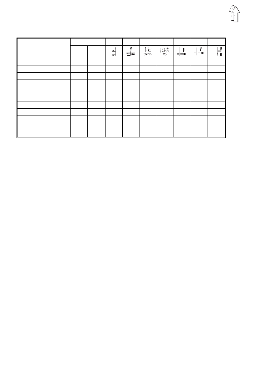
1.2 Technische Data
Sub-classes
max.
from
factory
mm
271-140041 5500 4800 4mm x
271-140042 5500 4800 4mm x x x
271-240042 5500 4800 4mm x x x x
272-140041 5000 4800 4mm x
272-140042 5000 4800 4mm x x x
272-160062* 5000 4000 6mm x x x
272-640141 5000 4800 4mm x x
272-640142 5000 4800 4mm x x x x
272-740142 5000 4800 4mm x x x x
273-140042 5500 4800 4mm x x x
274-140042 5000 4800 4mm x x x
* Extra-large shuttle = 70% greater capacity of the underthread spool than with the
standard hook
To 1: Max. sti tch length for each sub-class
To 2: Thread trimming for needle and bobbin thread
To 3: Electro-magnetic automatic bartack. I t is switched via the pedal and executes
the followi ng functions: l o wering the pres sure foot, seam beginning and seam
end bartack, needle and bobbin thread trimming, raising the pressure foot.
To 4: Keys on the arm head:
- Needle high - low
- Bartack on - Bartack funct ion switched off at the contr o l panel
- Bartack suppressed - Bartac k function swit ched on at the control panel
- Bartack within the seam
To 5: Edge cutter right, next to the needle. Switched on and off with the hHand lever
or, as optional equipment, electro-pneumatically via key. Depending on the
sewing unit (E -no.), the cutt i ng interval is 3.5 ; 5.0 ; 8.0 or 10mm . Special
sewing devic es are required for graduated cutting. The knife stroke is 5.5mm .
To 6: Edge cutter, but with seperate electric drive. Two cutting rpms can be switched
in.
To 7: Edge cutter, which cuts into the material edge crosswise during sewing, e.g. for
tension-free turning over of round neck openings, collars, arm holes, etc. The
cut occurs after every 6 stitches. On request after 4 stitches. The cut depth has
a max. of 15mm. It is adjust able up to abou t 1mm to the seam.
Stitches/min 1 2 3 4 5 6 7
Needle system: 134, 797 or Sy 1955-01
clearance under the pressu re foot
When raised: 8.0mm by 271 and 273
9.5mm by 272 and 274
When sewing: 8.0mm
Operating press ure: 6 bar
Air consumption: 0.02 Nl per wor k c yc l e by 273 and 274
0.1 Nl per work cycle by 272-740142
6

Noise Level Lc: Work station specific emmission value to DIN
45635-48-A-1-KL2 by stitch length 3.2mm
271-140041 and 140042 with stitches 4800/min. = 80
dB(A)
272-140041 and 140042 with stitches 4800/min. =
82dB(A)
272-140041 and 140042 with stitches 4500/min. =
80dB(A)
1.3 Optional Equipment
App. 301 Covering hood for the machine head
Z 120 1801 Electro-magn et i c thread wiper for 271 and 272
Z 120 1851 Electro-magn et i c thread wiper for 273 and 274
Z 133 371 Reflected li ght barrier for automatic sewing stop at
Z 116 6741 Electro-pneum atic device for al ternating sewi ng with
Z 124 401 Electro-pneumatic operation for on/off switching of
Z 145 1 Graduated ed ge cutting (finger version for lightest
Z 145-101 Graduated edge cutting (2 knife version for m edium
722 2041 Container for cutting wa st e for connecti on to the
999 260029 for 3-phase current 380-400V+N, 50Hz
999 260030 for 3-phase current 220-230V, 60Hz
999 260031 for 3-phase current 415-440V, 50Hz
933 5736 Toothed steel r ol l er, 9mm wide for 273 and 274 roller
273 1041 u. 27 4 1141 Height setting for the pressure foot with har d to
570 1833 Filter regulator for the compressed air connection
271 661 Parts set, knee lever for pressure foot lift by
271 1671 Parts set, hand lever for seam bartacking for
sub-classes -140000 and -160000
the material end with follow-up functions. For motors
with external control panel V730 or DB5.
two differently set stitch lengths and two differently
set needle thread tensions. Normal seam and seam
with thread drawing (bast i ng stitches). Pa rtial
strengthened tension (Seam thickening) and
ornamental seams.
the edge cutters via key for 272-640142.
materials). In conjunction with the sewing unit 272/E
111 for widths of cut of 4.5 and 7mm.
heavy material). In conjunction with sewing unit
272/E 112 for widths of cut of 3.5 and 6,5mm.
in-house va cuum system. If t his is not available then
the appropri ate centrifugal blower is to be used.
transport
transport material, e.g. velvet.
machines with automatic bartacker.
machines with automatic bartacker.
7

2. Machine Elements and their Functions
2.1 Elements on the Machine Head
Element Function
1Screw – Regulating of the pressure fo ot pressure. The
2Hand lever – Turning the edge cutter 10 on and off. The position
3Spooling devi ce – See under Sect i on 3.2 Spooling of t he Bobbin
4Control panel – See the motor manufacturer’s instructions.
5Oil reservoir – The oil l evel should not be al l owed to drop bel ow
6Adjustment wheel – Setting the stitch length for reverse sewing (with
7Adjustment wheel – Setting the stitch length for forwardsewing (with
8Rest – For tilting the m achine head to the back (not on
9Needle thre ad tension – Turn in direction + = h i gher needle thre ad tension
10Edge cutte r – Function see following page.
11Needle – System 134, 797 or Sy 1955-01
Setting of the screw is to be f ixed.
of the hand lever is variablly adjustable.
Thread.
"MIN". When necessary fill with ESSO SP-NK10 oil
to "MAX".
sub-classes -....41 via hand lever).
sub-classes -....41 via hand lever).
classes 273 and 274).
Turn in direction - = looser needle thread tension
- Risk of Injury! -
Before replacing the needle it is essential to turn the main
switch off.
12Locking button – Lock the pressure foot in the raised position
13Hand lever – Setting the carrier roller up. It is swung out of the
14Adjustment wheel – Transport length for the top feed roller
15Roller to p feed – Function se e following page
work area. Sewing only with bottom feed
8

E
l
e
m
e
n
t
272-640142
12 3
15
13
101112 9 8 7 5 4
14
6
274-140042
9

Element Function
16Separate drive
for edge cutter
17LED – The blink i ng of the diode shows that the edge cutter
18Switch for
edge cutting
19LED – Indicator for main switc h " On" (only 272-74 0142)
20Key – Beginning or end bartack on - Bartack off at the
21Key – Single stitches
22Key – With sewing machine at rest: Needle up-down.
23Key – Switching the edge cutter on and off. By sub-class
24Key – Raise and lower the top feed roller manually.
25Knee lever
(only sub-classes -....41)
26Hook lubrication – The oil reservoir for the hook lubrication should not
– Two cutting rpms switchable (only 272-740142)
- Risk of Injury! -
Caution in the area of the edge cutter.
is operationally ready. To switch on and off the
following variants are available:
* Manual via key
* Via the sewing pedal through the run signal of the
sewing drive
* Automatic "On" or "Off" after a selected number of
stitches
* Automatic "Off" after thread trimming (See
Installation Instructions Section 13.)
– I = Normal rpm
D = Drive "Off". Knif e outside the sew i ng area
II = Increased rpm for greater stitch lengths and thick
materials
control panel
Beginning or end bartack off - Bartack on at the
control panel
With sewing operation: Bartack ( reverse sewing) at
desired position in the seam
272-640000 t he pneumatic oper ation Z124-401
(optional equipment) must have been installed.
Otherwise the key has no function.
Automatic lowering afte r a number of stitches see
Installation Instructions Section 12.
– Before tilting the machine head to the back turn the
main switch off and remove the knee lever. To slip it
out conduct movements 1 and 2 and to hang it back
in movements 3 and 4.
drop below the " Min" mark.
By normal oper ation the oil level should be ch ecked
weekly. Through the fill opening fill Esso SP-NK 10
oil up to the "Max" mark.
The oil flow for the hook lubrication can be regulated
at screw 5.
10

272-740142
16 1918
17
20
21
23
22
20
21
22
24
OIL SP-NK 10
5
26
11

2.2. Elements on the Frame
Elements Function
1Main Switch – Turn the sewing drive on and off.
The sewing machine head is operational.
Attention!
For threading, replacement of sewing tools (such as
needle, pressure foot, needle plate, material feed etc.),
cleaning, w hen leaving the work place as well as during
maintenance work it is essential to turn the main switch
off.
See also General Safety Notes.
2Pedal –
Maintenance unit
6Air filter and
7Water seperator
4Pressure regulator – For setting the air pressure at 6 bar pull up and
9Oil Mister – The oil mister provides the solenoid valves and
Rest position. No function.
A
Raise pressure foot during mac hi ne rest
B
Sewing to a m aximum number of stitches by
C
appropriate s t ep down.
Seam bartacki ng* - Thread cutting - Raise
D
pressure foo t*
*Not with sub-classes -....41
– Before the water level reaches the air filter 6 screw
in screw 8 and relaese the water under pressure.
adjust the knob 4.
Turn to the right = Pressure increase
Turn to the left = Pressure decrease
cylinders with lubricating oil .
With the regul ating screw 11 set at app rox. 1 drop of
oil for 15 work cycles.
To fill the mister 9 turn off the compressed air. Do
this by pulling up the knob 4 and turning to the left.
Screw out screw 10 and fill Esso SP - NK 10 oil up to
the grooved marking of the oil reservoir.
12

1
2
A
C
11
4
5
A
B
D
10
6
7
8
9
13

3. Operation
3.1 Needles, Threads and Thread T ension
Needles of the systems 134, 797 or Sy 1955-01 are to be
used.
When inserti ng the needle care is to be take n that it is
pushed in until contact is made and that the furrow of the
needle is turned to the right, e.g. to the hook tip.
The following t able shows for each needle thickne ss the
recommended t hread thickness, thread tension and t
thread regulator setting.
Needle
Thickness
70
80
90
100
110
120
1) Transport leng th 2. 5 m m a nd nu mb er of st it ch es 50 00 /m in f. su b- cl . -1 40 04 1, -1 40 04 2, -6 40 04 1, -6 40 14 2
and-740142
1) Transport leng th 4 m m a nd nu mb er of st it ch es 40 00 /m in f. su b- cl . -1 60 06 2
Thread
Poly-Poly
Nm 95/2
Poly-CO
Nm 80/2
Poly-Poly
Nm 80/2
Poly-Poly
Nm 65/2
CO Ne 50/2
Poly-CO
Nm 50/2
Poly-Poly
Nm 30/3
Poly-CO
Nm 25/2
Needle
Thread
Tension1)
60-100 20-30 25-35 4 2.5
60-100 20-30 25-35 3.5 2
60-100 20-30 25-35 3.5 2
70-100
60-100
100-150 25-35 30-45 3 2
200-300 30-40 40-70 2.5 1.5
Looper Thread
Tension. 1)
Cl.271/273 Cl.272/274
Thread Regulator 1)
Sm. Hook Extra-large Hook
20-30 25-40 3 2
3.2 Spooling of the Bobbin Thread
Spooling occurs automatically with pressed on bobbin
winder flap 1 during sewing.
See the following illustration for threading the bobbin
thread from t he thread stand to the bobbin winder.
Remove the thread rests to be found on the bobbin hub
before spooling.
Pre-wind the bobbin thread to the right around the bobbin
hub.
Cut off the thread end in the cutting clamp 2.
The filled bobbin is removed in the same way.
14
1
2

3.3 Replacing the Bobbin and Setting the Looper Thread T e nsion
- Risk of Injury -
Turn the main switch off!
Removing the Bobbin
Lift up lid 3 and remove the upper part of the bobbin case
with the bobbin.
3
Inserting the Bobbin
The insertion of a new, filled bobbin can be seen in the
following illustration.
The thread is pulled in the slit a under the leaf spring b up
to the hole c. When the thread is pulled off the bobbin
must turn in the direction of the arrow.
Important Note!
In order that the bobbin brake spring 5 can move freely
the area behind it is to be cleaned
intervals
needle, and blow out.
Setting the Looper Thread Tension
With a recommended looper thread tension of e.g. 30g,
15g should be ac hi eved through the brake spring 5 and
15g through t he tension spring 7.
As the base position of the tension spring 7 the following
applies:
Allow the bobbin case to slowly lower through its own
weight. See sketch.
The brake spring 5 blocks the run-on of the bobbin during
thread trimming.
Set its braking effect sensitively.
of sewing dust. Raise the spring, e.g. with a
5
4
at regular work
6
67
15

To set the two tension values proceed as follows:
– Turn the regulating screw 6 so far back that the
tension of the leaf spring 7 is completely released.
– Set the brake spring 5 accordingly by turning the
screw 4.
– Insert the bobbin into the upper part of the bobbin
case and thread the looper t hread as per th e
illustration.
– Insert the bobbin case with bobbin into the hook.
– With a so-called air stitch pull the looper thread to
the top of the stitch hole wit h t he aid of the needle
thread.
– Pull off the looper thread at an angle of 45°. About
half of the tension value should be felt.
Then tighten the regulating screw 6 to the
recommended tension.
3.4 Threading the Needle Thread
- Risk of Injury -
Turn the main switch off!
The thread pa t h of the needle thread is shown in the
following illustrations.
For a, as far as possible, tensio n-free unwinding of the
threads fr om the thread stand thread through only one
thread hole of the unwindin g arm.
The other thread holes are clos ed with the plugs f ound in
the accessories package.
16
3
4

3.5 Regulating the Needle Thread T ension
Pre-tensioning for Thread Trimming
For the sure functioning of the thread trimming with
opened main tension 4 a small res i dual tension of the
needle thread is required.
This residual tension is achieved by pre-tensioning 3. At
the same time it influences the length of the cut needle
thread end. (Starting thread for the next seam.)
Short starting thread = tighten the knurled nut 3.
As base position applies:
Front of the knurled nut and bolt flush.
Greater adjustments of the pre-tensioning makes a
readjustmen t of the main te nsion necessary.
Main tension
Pre-tensionin g 3 and main tension 4 should give th e
recommended needle thread tension of e.g. 80g.
Set the main tension 4 accordingly.
3.6 Thread Regulator
With the thread regulator 6 the needle thread quantity
required for s t i tch building can be regulated. The set t i ng
is dependent on stitch length, material thickness and
thread characteristics.
Note:
Only a precisely set thread regulator assures an optimal
sewing resu l t.
The needle thread loop should glide over the hook
without excess and with little tension.
Loosen screw 9 and set the regu l ator accordingly.
The vertical wire 7 serves as a setting aid in conjunction
with the scale 8.
6
45
987
17

4. Maintenance
Note
With a correct regulator setting the thread controller
spring 5 will be pulled approx. 0.5 mm down out of its
upper end position when the thread loop passes the
maximum hook gi rth, that is, wh en the greatest am ount of
thread is required. See illustration.
The dimension 0.5 mm is a guideline. It can be greater or
smaller dep ending on the thread controller spring tension.
- Risk of Injury -
During cleaning and lubrication of the machine it is
essential to turn the main switch off.
The maintenance work must be conducted at the l at est
after the number of operating hours shown in brackets ( ).
Other maintenance intervals may result when working
special materials.
4.1 Cleaning and Checking
A machine kept clean protects against malfunctions!
– Remove sewing dust from under the needle plate.
– Remove the sewing dust collecting between the
– Clean the area below th e bobbin brake spr i ng 3 of
– Clean t he sewing dust f rom the motor ventilation
– If the machine is equipped with the compressed air
18
(8 hours)
This is best done wi t h a compressed air pistol.
transporter web. (8 hours)
Remove the needle plate for this.
sewing dust. (8 hours)
Slightly raise the spring 3 e.g. with a needle leicht
and blow out.
sieve. (8 hours)
maintenance unit 5 check the oil and water levels.

Before the water level rises to the filter insert 6 it is
essential that, with the maintenance unit under
pressure, the water be blown out of the water
seperator 7 after screwing in screw 8.
Water level in the water seperator 7 (40 hours)
Clean the ai r filter insert 6 (500 Std).
Check the oil flow of the oil mister 11 (180 hours)
See under Sect i on 2.2
3
11
4
10
5
6
7
8
9
19

4.2 Lubrication
For the lubrication of this machine it is essential that
Esso SP-NK 10 or an absolutely equivalent quality
lubricating oil be used.
The maintenance of the parts t o be provided with oil is
limited to the following:
– The oil level in the oil reservoir 1 may not drop below
the "MIN" mark. (40 hours)
With the machine upright fill oil to the "MAX" mark.
With the exception of the hook lubrication all bearing
positions on the machine are supplied via a central
oil wick lubrication from th e oil reservoir 1.
– The oil level in the oil reservoir 2 for the hook
lubrication should also not be allowed to drop below
the "MIN" mark. (40 hours)
With the machine head tilted back fill oil to the "MAX"
mark.
– When necessary fill the oil reservoir 9 of the
maintenance unit to the groove marking with oil. (40
hours)
For this completely shut off the compressed air by
turning the knob 4 to the left and then screwing out
screw 10.
20
Oil SP-NK 10
Oil SP-NK 10
1
2
 Loading...