

AC
AC SERVO MOTOR
伺
服
馬
達
DUERKOPP ADLER-251 專 用 操 作 說 明
書
INSTRUCTION MANUAL FOR DUERKOPP ADLER-251 MACHINE ONLY
HVP-20-4-25 FOR DA- 251
MINI-MOTOR
HSVP20U06 - 0 2006. 08
C-60
中 文 版
ENGLISH
Model : HVP - 20 Series
Conten
ts
1. Safety Precaution
(1). Work environment
(2). Safety in installation
(3). Safety in operating
(4). Safety in maintenance and repairs
(5). Regulation in maintenance and repairs
(6). Danger and caution signs
(7). Warranty information
………………………………………………………………………………………
………………………………………………………………………………………
……………………………………………………………………………………
………………………………………………………………………
…………………………………………………………………
………………………………………………………………………………
………………………………………………………………………………
2. Installation and Adjustment
(1). Control box installation
(2). Operation box installation
(3). Speed control unit adjustment
(4). Installation of the synchronizer
(5). Assembly of hand wheel
(6). Installati on of hand wheel
(7). Needle position adjustment
………………………………………………………………………………
………………………………………………………………………………
………………………………………………………………………
………………………………………………………………………
……………………………………………………………………………
………………………………………………………………………………
……………………………………………………………………………
3. Power Connection and Grounding
(1). Single phase and three phase connection
Φ
(2). How to connect 1
(3). The load balance when use 1Φ / 220 V motor used on 3 Φ / 220 V power source
(4). How to change solenoid supply voltage (DC 24 V or 30 V)
/ 220 V power from 3 Φ / 380 V power source
…………………………………………………………
……………………………
……………………………………
…………
Page
1
1
2
2
2
2
2
3
3
3
4
4
4
5
6
6
7
7
4. Part Name of the Control Box
(1). Use the following numbers cross reference with the contr ol box pictur e
(2). Exterior of the control box
…………………………………………………………………………
5. Key Function on Operation Panel / Box
(1). W hen use with F-10 mini panel / operation box
(2). When use with C-60 operation box
…………………………………………………………………
…………………………………………………
6. Parameter Adjustment
(1). How to enter【Normal Mode】
【
(2). How to enter
(3). How to set the【Parameter Value】with F-10 operati on panel
(4). How to set the
(5). Value setting for A、B、C、D key in the【Parameter Value
Parameter Mode】level
【
Parameter Value】with C-60 operation panel
…………………………………………………………………………
……………………………………………………………
……………………………………
……………………………………
】……………………………………
……………………
8
9
10
11
14
14
14
15
15

Page
P4
7. How to Use Re set Funct io n
8. Basic Troubleshooting
(1). Error code and measurement
(2). HVP-20 parts list
…………………………………………………………………………………………
9. HVP-20-4-25 Pin Assignment
………………………………………………………………
……………………………………………………………………
……………………………………………………………
Appendix :
(1). Level 1 parameter list
(2). Level 2 parameter list
…………………………………………………………………………………
…………………………………………………………………………………
Bottom page : 7-Segm ent Display Character s Compare Chart
16
17
19
20
P1
1
1. Safety Precaution
3 Φ 220 V
Green/
Yellow
Keep
away
When install and operat e HVP-20 MINI Servo Motor, precaution must be taken as the following.
This product is designed for the industrial sewing machines and must not be used for other purposes.
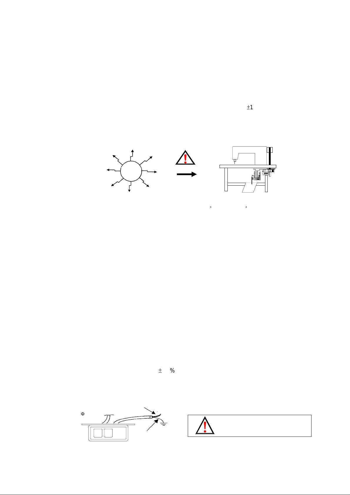
(1). Work environment :
(a). Power voltage:
Only use Power Voltage indicated on the name plate of the HVP-20 in
(b). Electromagnetic pulse interference:
To avoid the abnormal running, please keep the product away fr om t he high electromagnetic
machine or electro pulse generator.
Interference
(c). Temperature:
±
10 % ranges.
1. Please don’t operate in room temperature is above 45
°
C or under 5°C
2. Avoid operating in direct sun light or outdoors area.
3. Avoid operating near the heater.
4. Avoid operating in the area which humi dity is 30% less and 95% more, also keeps away from
dew area.
(d). Atmosphere:
1. Avoid operating in dusty area, and keeps away from corrosive material.
2. Avoid operating in evaporative or combustible gas area.
(2). S afety in ins tallat ion :
(a). Motor and control box: Follow the instruc tion in this manual for proper installation.
(b). Accessories: Turn off the power and unplug the cord before mounting any ac c essories.
(c). Power cord:
1. Avoid power cord being applied by heav y objec ts or excessive force, or over bend.
2. Power cord must not set to be near the V-belt and the pulley, keep 3 cm space or above.
3. Check the outlet voltage before plugging the cord, make sure it matc h the voltage shown on
the name plate of the HVP-20 in
±
10 % ranges.
(d). Grounding:
1. To avoid the static int erference and current leakage, all grounding must be done.
OFF ON
Power wire
Grounding
Ground Wire (Green/Yellow)
must be groundi ng.
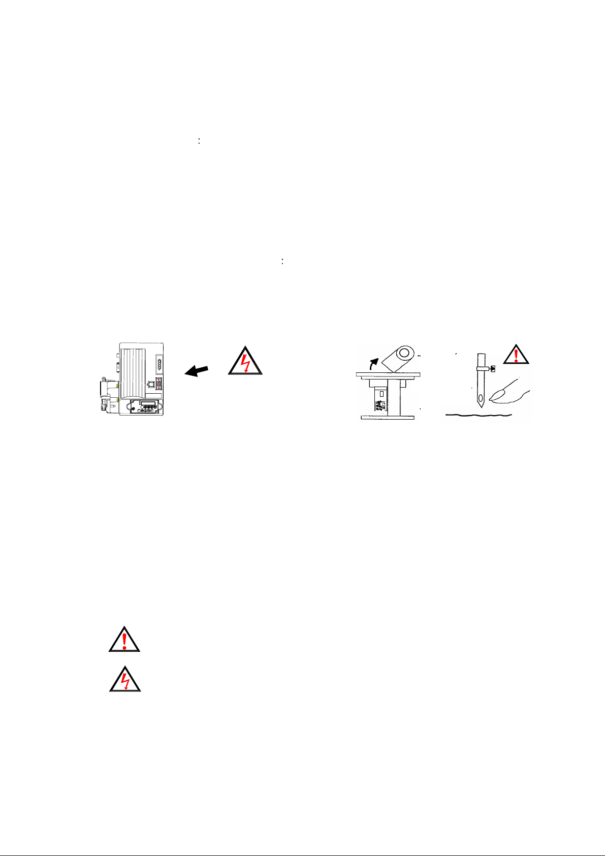
2
2. Use the correct connector and extension wire when connect ing ground wire to Earth and
secure it tightly.
(3). Safety in operating:
(a). When turn on the machine in the first time, use low speed to operate and check the
correct rotation direction.
(b). During machine operation, don’t touch any moving parts.
(c). All moving parts must use the protective device to avoid the body contact and objects
insertion.
(4). Safety in maintenance and repairs
Power must be turned off first, when:
(a).Uninstall the motor or the control box, or plug and unplug any connector.
(b).Turn off the power and wait 5 minutes before opening box cover.
High Voltage Inside
:
Head
Needle
(c).Raising the machine arms or changing needle, or threading needle.
(Shown as above)
(d).Repairing or doing any mechanical adjustment.
(e).Machines rest.
(5). Regulation in maintenance and repairs :
(a).Maintenance and repairs must be done by trained personnel.
(b).Don’t cover up motor’s ventilation, it can cause motor over heated.
(c).Don’t use any objects or force to hit the product.
(d).All spare parts for repair must be approved or supplied by the manufacturer.
(6). Danger and Caution Signs :
Risks that may cause personal injury or risk to the machine are marked with
this symbol in the instruction manual.
This symbol indicates electrical risks and warnings.
(7). Warranty information :
Manufacturer provides a limited warranty in respect of the products covered for a
period of 18 months for any defects arising in the normal course.
3
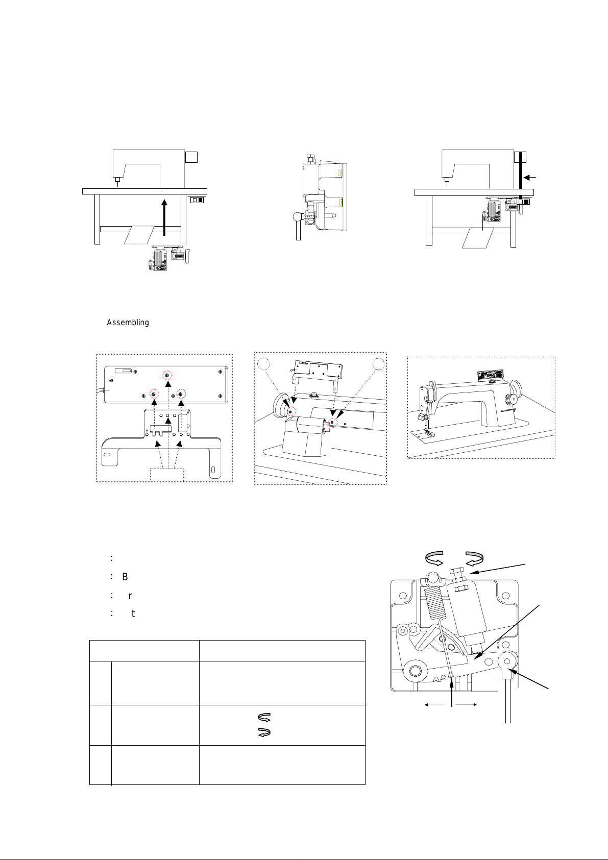
2. Installation and Adjustmen t
B A
B A
C D
(1).Control box installation :
a). Install the motor and control box under the table b). Install the pedal with speed control unit c).Finished diagram
Control box
and motor
(2).Operation box installation :
Pitman rod
Speed control
unit
V-belt
a). Assembling the operation box on
the bracket and secure screws.
Operation box
Bracket
Screw
(3). Speed control unit adjustment :
Comp onents of speed contro l unit : see figur e
A: Spring for toeing forward force adjustment
B
:
B olt f or heeling backward force adjustment
C
:
Treadle / Pedal arm
D
:
Pitman rod
b). Unscrew screw A, B an d m oun ting the
bracket on th e mac hine head.
c). Remember to secure the screw A, B
and plug the operation box connector
to control box.
D
BAC
F
E
H
G
SP
increase decrease
Term of adjustment
Toeing forward
1
force adjustment
Heeling backward
2
force adjustment
Adjustment result
Spring A moved to right = for ce increased
Spring A moved to left = force decreased
Bolt B turned = force decreased
Bolt B turned = force increased
decrease
increase
Treadle stroke
3
adjustment
Rod D secured at right = stroke is longer
Rod D secured at left = stroke is shorter
4
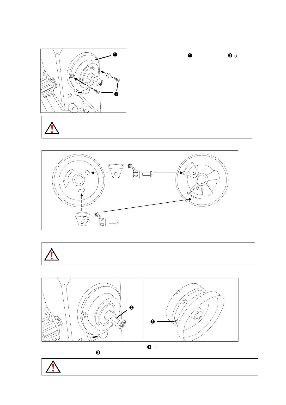
(4). Installation of the synchronizer :
(a). Fix the synchronizer with the screws on
the machine arm
WARNING:
You must use the copper screws to secure the synchronizer. If not so, it will cause the needle positioning
abnorm al an d also caus e the 2 m agn et s in th e han d wh eel to be demagn et iz ed .
(5). Assembly of hand wheel :
(a). Install the N and S magnets inside the hand wheel.
WARNING:
The positioning does not work properly if the N and S magnets are not installed correctly!!
The N pole magnet has a red dot on the magnet.
(6). Installation of hand wheel :
(a). Fix the hand wheel so on the arm shaft that the screw of the hand wheel (The first screw in turning direction)
is sitting on the flat area
WARNING:
Make sure that the hand wheel is not touching the synchronizer.
of the arm shaft and securely tighten the related screws.
5
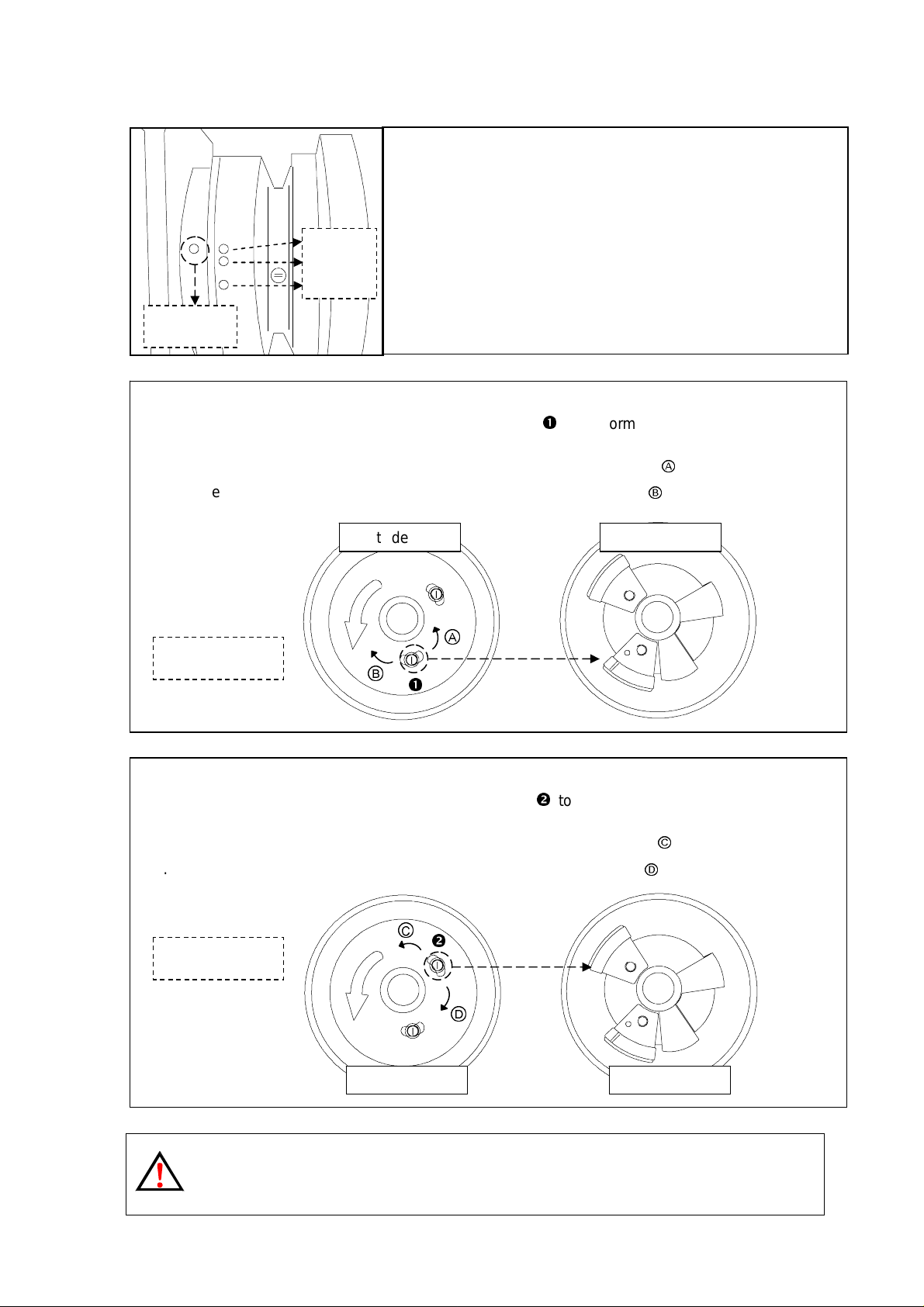
(7). Needle position adjustment :
Red
Out
side view
Inside view
Out
side
view
Inside view
(a). After install the synchronizer and head wheel, t oe
down the pedal and let the mac hine r unning few
stitches, t hen c hec k the needle position.
White
Green
(b). If motor stop at up position, the top white dot on hand
wheel should be aligned with the index dot on the
sewing machine.
Index dot
(c). Up positi on ( or positi on aft er trimming) adjustment :
Stop the needle in its highest position, loosen scre w
to perform adjustment
within the slot of the screw.
1. The needle stop timing is advanced if you adjust the screw in dir ection
2. The needle stop timing is del ay ed if you adjust the screw in directi on
Ⓐ
Up position
Ⓑ
Ⓑ
Ⓐ
.
.
(d). Down position adjustment :
Stop the needle in its lowest position, loosen screw
to perform adjustment
within the slot of the screw.
Ⓒ
Ⓓ
.
.
1. The needle stop timing is advanced if you adjust the screw in dir ection
2. The needle stop timing is del ay ed if you adjust the screw in directi on
Ⓒ
Down position
Ⓓ
Note :
If you have an y qu es t i on ab out needle position adj us tm en t , pl ease cons ult wit h the sewing m ach in e dis tr i bu tor or
sewing m ach in e m ec h anic ian.
6
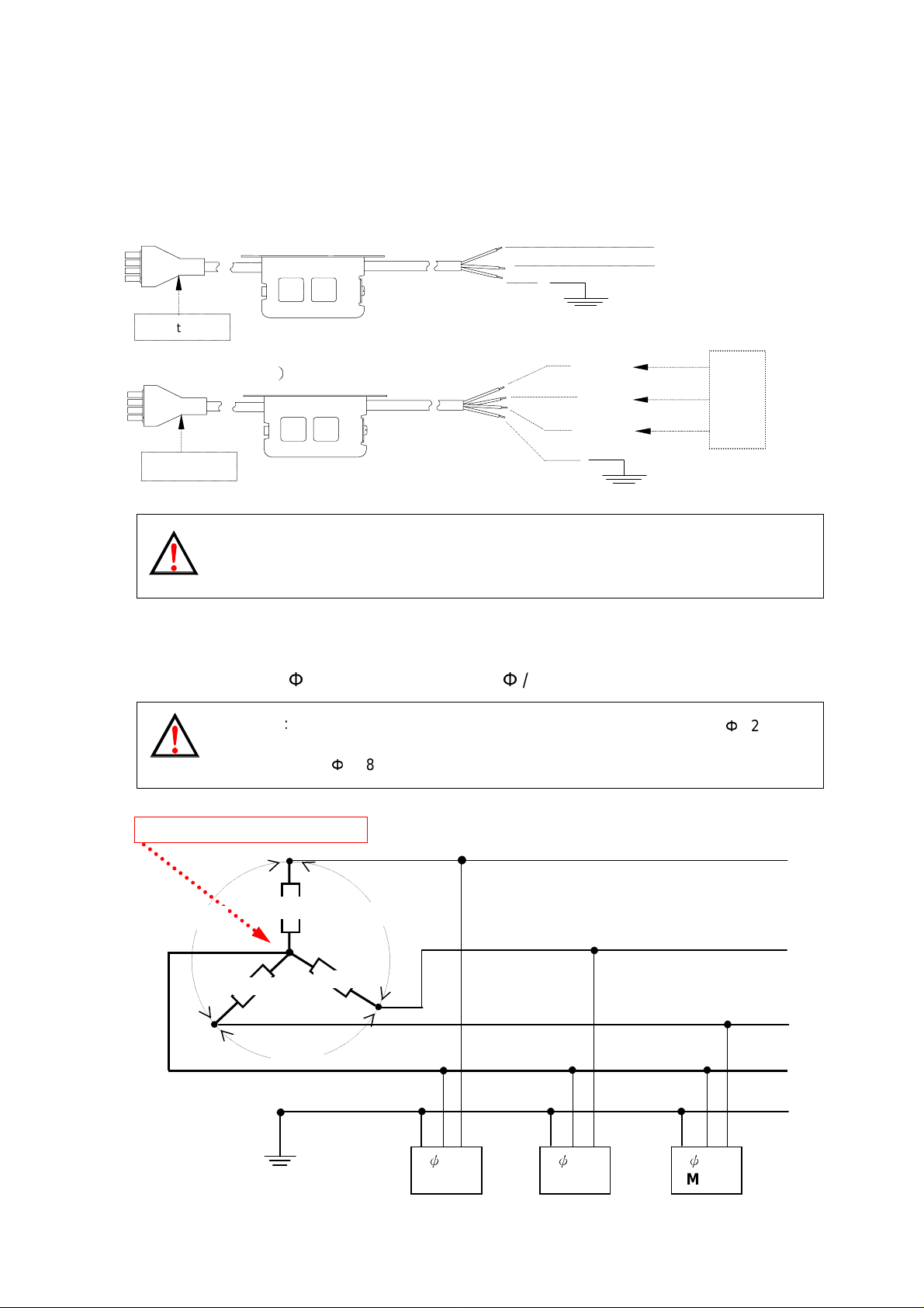
3. Power Connection and Grounding
L1
L1
L1
L2 L2 L2
(1). Single phase and three phase connection :
Green/yell ow wire is the ground wire.
Single Phase ( AC220V)
To control box
Three Phase ( AC380V)
To control box
Caution : Green / Y ellow wire must be grounded.
OFF ON
OFF ON
Brown
Blue
Green
Brown
Black
Blue
/ Yellow ( groundi ng w ir e )
R
S
T
Green / Yellow ( gr oun di ng w ire )
(2). How to connect a 1Φ / 220 V power from a 3 Φ / 380 V power source :
Caution
:
If the power source does not have the neutral point, then this 1Φ / 220 V
servo motor is not sui table f or this connec tion. Please ask supplier to offer
our 3Φ / 380 V servo motor.
Caution: Must have a Neutr al point
380V
220V
380V
220V
220V
Neutral
380V
Grounding system G G G
1
ψ
220V
Motor
1
ψ
220V
Motor
1
Motor
ψ
R
S
T
N
PE
220V
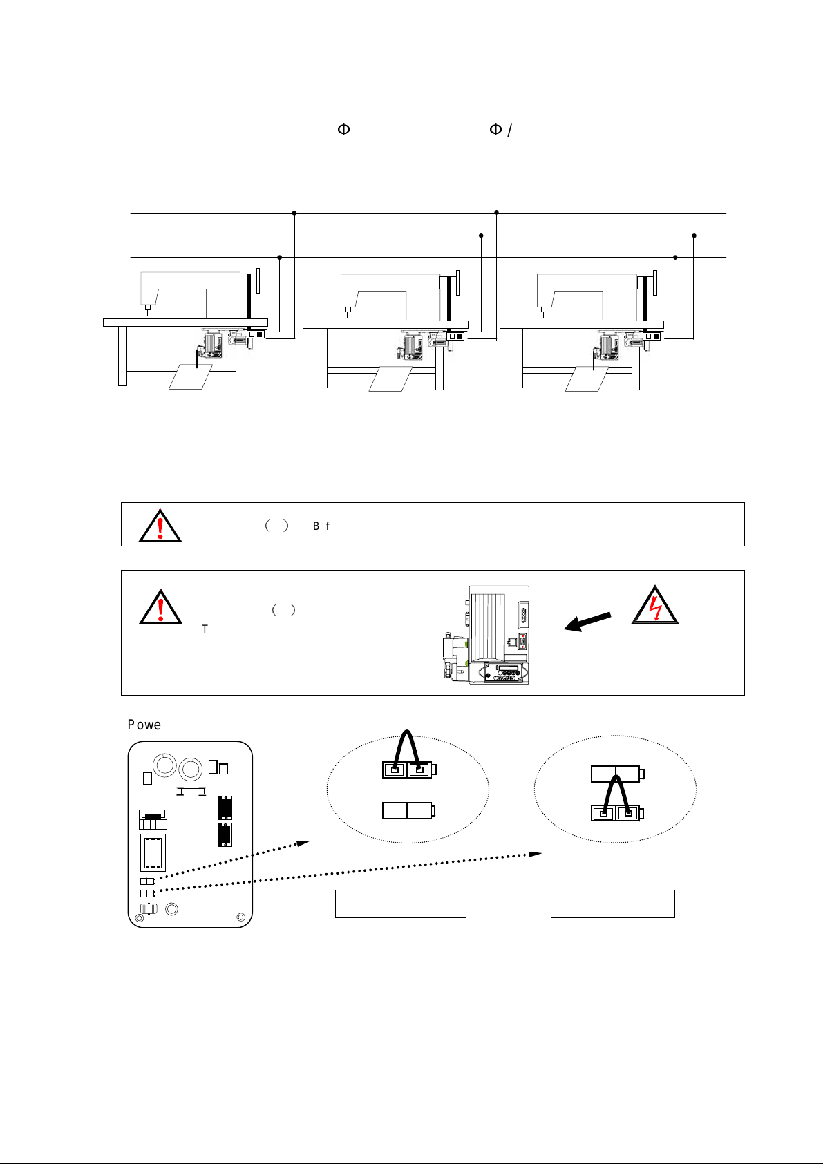
7
(3). The load balance when using 1Φ / 220V motors in 3Φ / 220V power system :
S
T
High voltage
inside
HSV-PS
122
0XX
JP 1
30 V JP 2
JP 1
30 V
JP 2
Please install the power connections as the following diagrams for the load balance.
R
(4) How to change solenoid supply voltage : (DC: 24 V OR 30 V)
When changing the solenoid voltage to 24V or 30V, use the JP1 and JP2 on the power board to do
the jumper switch.
Caution (1): Before making the switch, check the machine head solenoid specification.
Caution (2):
Turn off the pow er and w ait for 5 min.
before opening the cover, then make the
change.
Power board layout :
24 V
24 V
30V jumper setting 24V jumper setting
Factory settin g

8
4. Part Name of the Control Box
2 3 4 5 6 7 8 9 10 11 12 13 14 15 16 17
(1). Use the following numbers cross reference with the control box picture :
1
: Mounting bracket for under table motor.
1
: Motor power socket
: Standing operation panel socket
: Motor encoder socket
: Safety switch socket
: Speed control unit
: Operation panel / box socket
: Motor encoder cable
: Motor power cable
: Motor body
: Belt guard
: External lamp socket
: Main power socket
: 7P synchronizer socket
: Presser foot signal output socket
: Sewing machine signal output socket
: Sewing machine signal output terminal panel
Be careful for all the connector shape and plugging direction. All connectors must be plugged and secured well.

9
(2). Exterior of the control box :
11 10 4 5 6 7 8 1 2 3 12 13 14 3 6 16 17 15
Control box front side
9
Control box right side Control box left side
2

10
5. Key Functions on Operation Panel / Box
End back tacking
: means half heeling
2 3 4 5 6
8
10 11 12
2 3 7 6 5 4 8 9 10 11 12
(1). When use with F – 10 mini panel / operation box :
1
NO.
1
Function keys for the
lock-stitch machine
Enter the parameter area Enter the parameter area Also act as parameter increm ent key
Needle up Needle up Invalid
Free sewing / Bar tacking
/ Constant stitch sewing
Start back tacking
ON / OFF
ON / OFF
7
9
Number of stitches of C section
Number of stitches of D section
Needle up / down
when m otor stop
Slow start
ON / OFF
Number of stitches of A section
(ranged in 0 ~ 15 stitch)
Number of stitches of B section
(ranged in 0 ~ 15 stitch)
(ranged in 0 ~ 15 stitch)
(ranged in 0 ~ 15 stitch)
Motor rotation i con /
Number of stitches display
Function keys for the
interlock stitch machine
Invalid
Invalid Parameter increment key
Invalid Parameter decrement key
Needle up / down
When motor stop
Slow start
ON / OFF
Cancel half heeli ng bac k
back invalid
Cancel trimm er
: means trimmer
function invalid
Cancel wiper
: means wiper
function invalid
Start constant stitch s ewi n g
: mean start constant
stitch function valid.
Motor rotation i con /
Special function display
Function keys under parameter mod e
Enter parameter value ar ea / param eter
value saving key
Invalid
Invalid
Parameter / value selec tion key
Parameter / value selec tion key
Parameter / value selec tion key
Parameter / value selec tion key
Parameter display
NOTE : When #8~#11 define as special function key, the parameter [134. KLK]
must set at ON.

11
(2). When use with C-60 operation box :
ACBD
Function KEY Operation of Sewing Machine
Start / End
back tacking
selection
EF
G
SP
H
Double start back tacking (A,B sect i ons)
Single start back tacking (A,B sections)
Half start back tacking (B secti on )
Double end back tacking (C,D sections)
Single end back tacking (C,D sections)
Constant stitch
sewing
Free sewing
Half end back tacking (C section)
1). As t he treadle is t oed dow n, consta nt-stitch s ew ing E、F、G or H
performed section by section.
2).Once the treadle returns to neutral intermediately in any one
section, the machine will stop immediately. When the treadle
toeing down again, the balanced stitches of E
on.
3).If the parameter
and automatically start trimming cycle and end back tacking at
the end of the l ast section E or H.
4).When using P1~PF f unction, P1~P4 default setting is 15
stitches, other unused sections must set 0 stitch.
1).As the treadl e is toed down, machine will start sewing . Once the
treadl e ret urn s to n eutr al , mac hi n e will st op immediately.
2).As the treadle heeled back, the trimming cycle will be finished
automatically.
【
010. ACD】is set ON, the machine will not stop
、F、
G or H goes

12
Bar tacking
A B C D
1
0
1
0
E
F
G H
1 5 1 5
E F
G H
A B C D
4 4 4
4
E F
G H
A B C D
As the treadl e is t oed down, all the seams of b ar tacking, A、B、C
D sections will be completed wit h E times, and the trimming cycle
will be finish ed aut oma tically
:
When the bar tack sewi n g start, it will not stop until the
Note
trimming cycle f inished, except for the treadle h eeli ng back to
A
E
cancel the action.
、B、C、
、F、G、
D -- stitch setting range i n 0 ~ F (Note)
H -- stitch setting range i n 0 ~ 99
、
Stitch setting
selection
Needle up / Forward
stitch correction
One-shot sewing
( AUTO )
----
----
----
∴
Press key to select : Top A、B、C、D
Middle E
Bottom G
A=B=C=D=4 stitches
E = F = 10 stitch e s
G = H = 15 sti t c hes
、
F
、
H
1). In free sewing:
One touch of this key act as stitch correction. (half stitch forward)
:
2).In constant-stitch sewing
a. I f sewing stops intermediat ely in one secti on, on e touch of this
key will raise t he needle to up position.
b. If sewing stops at the end of section, one touch of this key will
correct one stitch forward.
( In Bar-tack sewing, it act as needle up )
1). In free sewing and bar-tack sewing:
One touch of this key makes beep sound but no function; also LED
does not light up.
:
2). In Constant-stitch sewi ng
a. One shot to the pedal, automatic performed number of stitches
、F、G、
of E
b. Toeing d own th e pedal again to f ini sh the rest sectio ns until it
finis h patt ern.
H sections.
Trimming cyc le
selection
Enable or disable the trimming cycle.

13
Slow start
Needle up / down
when m otor stop
Presser foot up / down
after trimming cycl e
Presser foot up / down
when motor stop
1).When function is turned ON, slow start activat ed at first
run of motor start. After trimming, it will activ ate again on
next
motor start.
2). Speed of the slow start can be set by parameter [007. S].
3). Number of stitches can be set by parameter [008.SLS].
Needle stop setting
LED ON= Stop at UP positi on
LED OFF=Stop at DOWN position
Presser Foot action after trimming
LED ON= Automatic lift the presser foot after trimming
LED OFF=Presser foot not active after trimming..
Presser foot action when motor stop
LED ON=Motor stop, presser f oot goes up automatically.
LED OFF=Presser Foot not active when motor stop.
Value / Parameter
increment key
Value / Parameter
decrement key
Enter parameter area /
Parameter increment
Enter parameter value /
Saving
A、B、C、D section value increment key, range in 0~ F.(Note)
E、F、G、H section value increment key, range in 0~99.
A、B、C、D section value decrement key, range in 0~ F.(Note)
E、F、G、H section value decrement key, range in 0~99.
Press and hold this key f or 2 second to ent er parameter area.
Also act as parameter increm ent key
Press this key in parameter ar ea to ent er param eter value area.
Also act as the parameter v alue saving key.
Note
:
Stitches setting of A、B、C、D sections correspond to the alphabet.
A=10、B=11、C=12、D=13、E=14、F=15 stitches

14
6. Paramet er Adjustment
.
.
B C D
C-60 : see note.
(1). How to enter【Normal Mode】:
Just turn ON the power to enter
Display for lockst itch
Machine
【
Normal Mode】
Disp lay for interlock Machine / or
when parameter 134 KLK =ON
SP
(2). How to enter 【Parameter Mode】level:
Parameter Mode Operation First display Range for Parameter
POWER ON
POWER ON
Level 1
Level 2
Parameter
Mode A
Parameter
Mode B
RESET
At【Normal Mode
press key.
ACBD
EF
G
】
H
Parameter
Parameter #1 ~ 122
Return to factory setting
#
1 ~ 46
Note ※ When use C-60 operation box, the key for each mode is same as above.
(3). How to set the【Parameter Value】with F-10 operation panel :
Confirm the parameter you want to adjust. (See the parameter list) and follow the below steps t o adjust the
parameter value.
Step 1
:
Enter one of the【 Parameter Mode A or B 】.
Step 2: Press or key to select the target parameter number.
Step 3: Press key t o enter the parameter value.
Step 4
:
Press key t o adjust the value. A
Step 5: Press k ey to save the value and return to
【
Normal Mode】automatically.

15
(4). How to set the【Parameter Value】with C-60 operation box :
TERMS
A B C D
S
S
.
.
a. Enter on e of th e
【
Parameter Mode A to B
ABCD
】
b. Use or key to select the
target parameter number.
【
c. Use key to access
ABCD
value ar ea
】
GH
SP
FE
GH
SP
FE
d. Use the key under the
、B、C、
A
e. press key to s a ve th e val ue.
D area t o s et the value.
ABCD
GH
SP
FE
a. Hold for 2 sec.
c. Acce ss
e. Save
b. Select
Caution:
1. When motor running, the param eter area is locked and prohibited for access. The
parameter only can be adjusted when m otor stop.
2. Wrong setting of the parameter mi ght cause the abnormal operating and dam age the
sewing machine. You must fully understand the f unc tion usage and the setting effects
to make adjustment. Don’t try to adjust the parameter gropingly
(5). Value setting for A、B、C、D key in the【Parameter Value】:
IN TERMS OF SPEED 1000 spm 100 spm 10 spm 1 spm
IN TERMS OF ANGLE --------
IN TERMS OF TRIMMING 1000 ms 100 ms
SCALE
KEY
100 ° 10 ° 1 °
10 ms 10 ms
IN TERMS OF FUNCTION FUNCTION SWAP FUNCTION SWAP
※
1. Other than the function selection, each press of the key will start change the value from 0 to 9 。
2. IF use with F-10, When
See the chapter 5 (Page.10) for detail
【
134. KLK
】
set
。
『
ON
』
, it acts as special function
『
ON / OFF
』
key.
d. Adjust
Note
:
After value change, press key to save the value, otherwise the new value will be lost
when tu r ning powe r off.

16
7.How to Use Reset Function
OFF ON
OFF ON
OFF ON
a. Turn off the power first.
F-10
1. Before【Reset】, please confirm the current machine code and any special setting for
the parameter. Once reset and all the setting will retur n to t he factory default.
【
2. After
Reset】, If the machine code is not match with the m ac hine head. It could
damage the machi ne head or cause mac hine not working properly.
b. Press and hold key for F-10 or key for C-60 and turn on the
power. The LCD will show
【
FASET
】
and blink twice.
C-60
ACBD
EF
G
SP
H
ACBD
EF
G
SP
H
c. Blinkin g m eans the data been【Reset】and
LCD will return to【Normal mode
】
area.
ACBD
EF
G
SP
H

17
8. Basic Troub leshooting
(1). Error Code and Measurement:
Error Code
ER0. 1
ER0. 2
ER0. 4
ER0. 5
Cause of The Problem Status and Measurement
1. Power m odu le detect ed error.
2. Abnormal over curren t or voltage occurred..
E²PROM (IC3) r/w malfunction.
1. W hen pow er on , det ec ted high voltage
2. Conn ect t h e wr on g voltage or su pp l y pow er is too h igh.
3. F1 fuse open
1. When p ower on, detected low voltage
2. Connect the wrong voltage or supply power is too low..
Motor wil l be shut down.
Pleas e ch ec k the power module.
Pleas e ch ec k the power board over cur r ent circui try.
Motor wil l be shut down.
Replace the IC3 memory unit.
Motor an d m ach in e w ill be sh utt ing down.
Please check the AC power. (Too high)
Please ch ec k the power board.
Please check the F1 fuse.
Motor an d m ach in e w ill be sh utt ing down..
Please check the AC power. (Too low)
Please check the power board.
ER0. 7
ER0. 8
1. Bad connection at the motor connector.
2. Synchronizer (sensor) signal error.
3. Machine locked or object stuck in the motor pulley.
4. Sewing material is too thick.
Opera tion box linked to CPU interface had communication error
Motor an d m ach in e w ill be sh utt ing down.
Please check the motor or motor connection.
Please check the synchronizer (sensor) and its signal.
Please check the machine head to see if objects stu c k in the motor pulley, or rotate not smoothly.
Motor an d m ach in e w ill be sh utt ing down.
Please check the operation box.

18
Error Code
Cause of The Problem
Status and Measurement
ER0. 9
ER0. 11
ER0. 12
ER0. 14
ER0. 15
ER0. 16
ER0. 51
1. Machine solenoid shorted.
2. Main board power transistor is faulty.
If parameter 【121.ANU】 is set ON, but auto needle up is
malfunc ti on wh en the p ow er tur ned on.
Power on, n o s ync hronizer sig n al or not connected.
Using PSU signal without sewing material when【106. PSN】= OFF
Using PSD signal without sewing material when【106. PSN】= OFF
1. Safety switch is either faulty or ba d connection.
2. Parameter
1. Mot or overloads f or more than 20 s ec onds du ring one sew in g.
2. Mot or ’s c oil is def ec tive.
3. Machine head is too crude to rotate smoothly.
【
075. SFM】settin g n ot m atch the machi ne head mod el.
Motor sti ll c an ru n, bu t all output si gn als an d op eration b ox pattern s ewing funct i on w il l be in val id..
Ω
Please check the machine so lenoids ; or the solenoid resistance v alue is 2
Please check all the power transistors, which related to solenoid.
Motor and mac h in e will b e shu tti ng down .
Please check the synchronizer up position signal.
Please check the control box.
Please check the machine head to see if objects stu c k in the motor pulley, or rotate not smoothly.
Automa tic starts the clutch mode.
Please check the synchronizer. (also check the connection and model)
Motor stops.
Please check the
Motor stops.
Please check the
Motor stops.
Please check the safety switch.
Please check the parameter
Motor stops.
Please check to see if the machine head is too heavy to sew.
Please check to see if the sewing material is too thick to sew.
Pleas e ch ec k th e m otor coils t o see if it is defecti ve.
Please check the machine head to see if it is too crude to rotate smoothly.
「
PSU」sensor circuitry and its sign al .
「
PSD」sensor circuitry and its sign al .
【
075. SFM】setting, make sure it match machine head safety switch
less.
Digital Alphabet English Alphabet Cause of The Problem Status and Measurement
POWER OFF
EM STOP
1. AC power shut down or bad co nnection.
2. Power board OI 1 sensor circuitry faulty.
An emer g ency stop sig n al act i vated when P aram et e r
【
149. IND】= ES.
Motor stops
Please check the AC power and connection.
Please ch ec k the power board OI 1 circ u itry.
Motor emergent stop.
Res t art the p ower to return normal ope ration.

CE
1. Motor Parts :
(2).
HVP
-
20 Parts List :
1-1
1-2
2. Control Box Parts :
2-1
2-2
2-3
1-4
2-4
2-6
2-5
1-5
2-7
2-17
2-9
2-11
2-10
1-6
SP
2-16
E F
G H
DBAC
2-5
2-14
2-12
2-8
2-18
Order Code Parts Name Descripti on
1 2VP3432209A XL Motor with bracket
1-1 315BGV150 Belt Cover Top For V-Belt Type
1-2 2VP2PY4041D Pulley (65 mm)
2VP2PY4061D Pulley (75 mm)
2VP2PY4081D Pulley (85 mm)
1-3 315BGV140 Belt Cover Base For V-Belt Type
VP-50AB0079800 170 02 8
∮
hole)
(14
∮
hole)
(14
∮
hole)
(14
2-13
NO. Order Code Parts Name Description
2-5 2VP20106003 Speed Control Unit 9800 370003
2-6 2VPPPW0210 Power Cable For HVP-20
2-7 2VPMPB207 Control Box Casing For HVP-20
2-8 32QRCH080 6P Connector For HVP-20
2-9 32ZVPB700 Connector Panel For HVP-20-4-25
2-10 315MPB600 Connector Panel (A) For HVP-20-4-25
1-4 313BGE030 Cover Bracket For V-Belt Type 2-11 2VP20103209 Power Board
1-5 2VPFRR432X8 Motor body
1-6 2VPBTV030 Motor bracket
500W
For under tabl e
2 2VP2040025201 Control Box 9800 370002
2-12 2VP20402001 Main Board For HVP-20-4-25
2-13 315MPB580 Front Cover For HVP-20
2-14 2VPOPBF01001
F-10 Operation
panel
2-1 313MPB190 Rear Cover For HVP-20 2-15 322PWG340 F-10 EXT. cable 1 m.
2-2 2VPPCB380 EMI Board For HVP-20
2-3 2VP20104202 Cement Resistor 220Ω 30W
2-16 2VPOPBPT0P
2-17 2VPOPBC06008 C-60 Operation box 9800 360 10 3
Operation bo x
bracket
2-15
For 1
∮
200-240V
15A
9800 360 10 2
D type
2-4 32QRCH270 2P Connector 5559-02P
2-18 2VP11800025 Sync hronizer 800-2H / 9800 367 10 2

20
9. HVP-20-4-25 Pin Assignment
FOOT SWITCH
+12V
1
START
2
VC3
KNEE SW.
4
0V5
6
TRIMMER
External
variable
resister
3
2
1
6
5
4
FOOT SWITCH
ENCODER
ENCODER
1
+5V
5
1
2UP
DOWN
3
A PHASE
4
B PHASE
5
R
6
S
7
8T
9
0V
+12V
1
2INL
INB
3
0V4
SYNCHRONIZER
DOWN
1
NO SYNC.
2
30V
40V
+5V
5
6UP
7 ---
1
OF
2
+24V
1
OA
2
OB
4
53INE
OC
6
+24V
7
+24V
8
+24V
9
EARTH
10
11
12
0V
13
+24V
14
OD
SAFETY SW.
+12V
SAFETY SW.
PSD
0V
FOOT LIFTER
A.F.L. SOL.
+24V(SWITCHING)
SEWING MACHINE
TRIMMER SOL.
WIPER SOL.
---
---
REV. SW.
REV. SOL.
+24V
+24V
+24V
EARTH
---
0V
+24V(SWITCHING)
TENSION
+12V
MT
MW
MR
ML
3
42
SAFETY SW.
MP
1
SYNCHRONIZER
1
FOOT LIFTER
SEWING MACHINE
3
527
46
1
7
6
5
4
3
2
1
OPERATION BOX
2
14
13
12
11
10
9
8
OPERATION BOX
+12V
1
5
21CKU
3
T1out
4
R1in
5
---
U SW.
6
---
7
---
8
90V

HVP -20 Parameters List V2-1.0K E1 for DA-251 (MAC. 35)
Parameters
Key
Code
1 H Maxim um sewi n g sp eed 50 - 9999 spm 4000 Maxim u m speed ad j u stments
P
O
2 SLM Slow start operation mode T/A
W
E
R
3 CNR Counter ratio selection 1 - 100 1
..
O
4 N Start b ack-tacki n g speed 50 - 8000 spm 1900 Start b ack-tacki n g sp eed ad j u stments
N
5 V End back-tacking sp eed 50 - 8000 spm 1900 End back-tackin g sp eed ad j u stments
6 B Bar -Tacking Sp eed 50 - 8000 spm 1800 Repeat bar-tacking sp eed ad j u stments
7 S Slow start speed 50 - 2000 spm 400 Slow start speed adju stments
8 SLS Stitch numbers fo r sl o w star t 0 - 99 stitches 2 Slow start stitch es setti n g
9 A Automatic con stant-stitch sewing sp eed 50 - 8000 spm 4000
11 RVM Back-tacking mode selecti o n
12 SMS Mode selection fo r Star t b ack-tacki n g
13
14
Mode selection at the end o f Star t b ack-tacki n gTYS
Start back-tacking fu n cti o n sel ecti o nSBT
15 SBA Setting stitches A of Star t b ack-tacki n g 3
16 SBB Setting stitches B o f Star t b ack-tacki n g 3
17 SBN Setting turn s o f Star t B ack-tacki n g 0 - 4 times 2
18 BT1 Stitch balance fo r Star t B ack-tacki n g 4 BT1= 0:Invalid , 1-8:Increase stitch es o f r ever se seam,9-F:Increase stitch es o f fo r war d seam .
19 BT2 Stitch balance fo r Star t B ack-tacki n g 3 BT2= 0:Invalid , 1-8:Increase stitch es o f fo r war d seam,9-F:Increase stitch es o f r ever se seam .
Mode selection for En d b ack-tacki n gSME20
21
End back-tacking sel ecti o n ON/OFF
EBT
22 EBC Setting stitches C o f En d b ack-tacki n g 3
23 EBD Setting stitches D o f En d b ack-tacki n g 3
24 EBN Setting turn s o f En d b ack-tacki n g 0 - 4 times 2 Setting the seam times of End b ack-tacki n g ,
25 BT3 Stitch balance fo r En d B ack-tacki n g 3 3 BT3= 0:Invalid , 1-8:Increase stitch es o f r ever se seam,9-F:Increase stitch es o f fo r war d seam .
26 BT4 Stitch balance fo r En d B ack-tacki n g 4 3 BT4= 0:Invalid , 1-8:Increase stitch es o f fo r war d seam,9-F:Increase stitch es o f r ever se seam .
27
Setting time interr u p ti o n at each secti o n en d o f
Back-Tacking.
Parameters Function Range Pre.setting Description
The slow start operation mode is selected. This is valid when the panel [SL] key is ON in the normal mode.
:
Slow start operation will begin when the power is turned ON or when the first toe down after thread trimming,
T
T
or the first exter n al r u n si g n al (S0, S1) i s tu r n ed ON .
A
:
Slow start operation will begin when the pedal is toed down or when the external run signal (S0,S1) is turned ON.
Setting the multip l e to th e val u e o f
Connection :【042. CUD】,【159. O4】,【097. TK3
Valid only at the auto pattern sewing or one shot signal
【
042. CUD
】
】
(SH)
active
Only at the last seam of pattern sewi n g
ONON/OFFAutomati c sewi n g En d b ack-tacki n g10 ACD
ON
:
Valid.
:
Invalid.
OFF
J = JUKI mode , B = BROTHER mode.
J/B J
J
:
Active when motor stop or running
:
Active only when motor running
B
Start back-tacking mode sel ecti o n
A
:
A/M/SU/SD
A
One shot sewing
:
Pedal control and motor can stop at middle way.
M
:
One shot sewing but motor stops at needle up by [027.CT] timer at end of each seam.
SU
:
One shot sewing but motor stops at needle down by [027.CT] timer at end of each seam.
SD
Mode selection at the end o f Star t b ack-tacki n g
CON
:
CON/STP/TRM
CON
At the end of Start back-tacki n g , machin e co n ti n u es sewi n g i f pedal pressed o r START si g n al o n (stan d i n g o p er ati o n )
:
At the end of Start Back-Tacking, machine stops and must re-start by pedal command.
STP
:
Making the trimmi n g cycl e o n ce th e Star t B ack-Tacking fi n i sh ed . ( Mini B ar tacki ng )
TRM
Valid only when the operation panel disconnected.
ON/OFF
0 - 15 stitches
ON
ON
:
Perform
:
Not perform
OFF
Start back-tacking sti tch es setti n g ,
Setting the seam times of Start back-tackin g ,
【
014. SBT】= ON valid
【
014. SBT】= ON valid
0 - F
End back-tacking mode sel ecti o n .
:
One shot sewing.
A
A/SU/SD
A
:
One shot sewing but machine stops up position by 【027. CT】 timer at th e en d o f each seam.
SU
:
One shot sewing but machine stops down position by 【027. CT】 timer at th e en d o f each seam.
SD
Valid only when the operation panel disconnected.
ON
ON
:
Perform
:
Not perform
OFF
0 - 15 stitches
End back-tacking sti tch es setti n g ,
【
021. EBT】 = ON valid
【
021.EBT】 = ON valid
0 - F
【
500 - 990 msCT
012. SMS】,【020. SME】, 【031. SMB】= SU,SD setting valid.
【
Conner stop timer, valid only at
012. SMS】,【020. SME】,【031. SMB】setting SU/SD .
PAGE - 1

HVP -20 Parameters List V2-1.0K E1 for DA-251 (MAC. 35)
Parameters
Key
Code
P
O
28
W
E
R
..
O
29 SB9 0-99 stitches p l u s o n Star t/ En d b ack-tacki n g 0 - 99 sti tch es 0 Addi ti o n al setti n g sti tch es ar e ad d ed to th e Star t an d En d b ac k-tacki n g sti tch es.
N
30
15 stitches plus o n Star t/ En d b ack-tacki n g
SB5
(with C60)
Mode selection for foot lifting .
AFM
(with F-10)
Added 1 stitch to th e C seg ment of En d b ack-
BCC
tacking
SMB
Mode selection for B ar -tacki n g
Bar-tacking sel ecti o nBAR32
33 B R C Settin g sti tch es o f B ar -tacki n g 0 - 99 stitches 4
34 B R N Settin g tu r n s o f B ar -tacki n g 0 - 15 times 4
35 BT5 Stitch balance fo r B ar -tacki n g 5 4 BT5= 0 : Invalid , 1-8 : Increase stitch es o f r ever se seam; 9-F : Increase stitch es o f fo r wa r d seam.
36 BT6 Stitch balance fo r B ar -tacki n g 6 3 BT6= 0 : Invalid , 1-8 : Increase stitch es o f fo r war d seam; 9-F : Increase stitch es o f reverse seam .
Constant-stitch sewi n g sel ecti o nPM38 OFFON/OFF
Setting stitches fo r secti o n 1
39 PS 0 - 250 stitches
stitch sewing
Setting stitches fo r secti o n 5
stitch sewing
Parameters Function Range Pre.setting Description
Additional 15 stitches are added to the Start and End back-tacking stitches function selection.
ON/OFF
OFF
ON
OFF
:
:
Valid.
Invalid.
0. Depends on the pedal.
1. At moto r sto p .
00/1/2/3
2. At trim ming after .
3. At trim ming after & at motor sto p .
Added 1 stitch to the C segment of End back-tacking function selection.
ONON/OFF
ON
OFF
:
:
Valid
Invalid
Bar-tacking mode selection.
A
:
A/M/SU/SD31
A
One shot sewing.
:
Pedal control and motor can stop at middle way.
M
:
One shot sewing but motor stops at needle up by 【027. CT】 timer at en d o f each seam.
SU
:
One shot sewing but motor stops at needle down by【027. CT】 timer at en d o f each seam.
SD
Valid only when the operation panel disconnected.
OFFON/OFF
ON
:
Perform
:
Not perform.
OFF
One setting for al l seams ,
Setting the seam times of Bar-tackin g ,
【
032. BAR】 = ON valid.
【
032. BAR】= ON valid.
0 - F
Constant-stitch sewing mode selection.
A/M
MMode selection for Constant-stitch sewingSMP37
:
One shot sewing.
A
:
Pedal control and motor can stop at middle way.
M
Valid only when the operation panel disconnected.
ON
:
Perform.
:
Not perform.
~
4 of Constant-
~
D of Constant-
OFF
15
Stitches setting o f seam P1-P4.
0
Stitches setting o f seam P5-PD.
【
038. PM】 =ON valid.
【
038. PM】 = ON valid.
PAGE - 2

HVP -20 Parameters List V2-1.0K E1 for DA-251 (MAC. 35)
Parameters
Key
Code
40 WON Wiper function selecti o n ON / OF F
P
O
W
41 TM Tri mmer function selection ON/OFF
E
R
..
O
N
42 CUD
Count mode selection
(For Bobbin Thread or Sewing Piece)
43 UD Setting the count 1 - 9999 99
44 PN Display the current count 0 - 9999 0
45 SP Sewing sp eed 0 - 8000 0 Showi n g th e cu r r en t sewi n g speed.
46 DIR Direction of motor rotation CW/CCW CCW
Parameters Function Range Pre.setting Description
Wiper function selection.
ON
ON
:
Enable.
:
Disable.
OFF
Trimmer function selection.
ON
ON
:
Enable.
:
Disable.
OFF
Counter function mode selection.
NOP
:
The counter is invalid.
:
Count up by stitches. When count over , counter will be auto- reset.
U
:
Count down by stitches. When count over , counter will be auto- reset.
D
US
:
Count up by stitches. When count over, motor stops and the counter must be reset by the external switch S4
【
152.INI】=CRS or the A key on the front panel..
:
NOP/U/D/US/DS/
UT/DT/UT S/DT S
NOP
Count down by stitches. When count over, motor stops and the counter must be reset by the external switch S4
DS
【
152.INI】=CRS or the A key on the front panel..
UT
:
Count up by trimming. When count over , counter will be auto- reset.
:
Count down by trimming. When count over , counter will be auto- reset.
DT
UTS
:
Count up by trimming. When count over,
motor stops and the counter must be reset by the external switch S4
:
Count down by trimming. When count over,
DTS
motor stops and the counter must be reset by the external switch S4
Count setting . (Note: The real number = the value of
【
042.CUD】= U,D,US,UD valid only.)
when
Display the current count of
Motor rotation d i r ecti o n ad j u stments. ( Vi ewed fr o m the motor sh aft si d e )
Connection :
【
119, DD
CCW :counterclockwise.
:
clockwise.
CW
PAGE - 3
【
152.INI】=CRS or the A key on the front panel.
【
152.INI】=CRS or the A key on the front panel.
【
003.CNR】X【043.UD】,
【
043.UD
】
】

HVP -20 Parameters List V2-1.0K E1 for DA-251 (MAC. 35)
Note : When
【
134.KLK
】
= ON for interlock-stitch machine, this function can be controlled by A key on the control box
Parameters
Key
Code
47 MAC Machine Code 0 - 101 35 Machine code swi t ch o ver
48 N12
+
49 SPD Machine's pull ey d i mensio n . 1 - 250 mm 75
50 MPD Motor's pulley dimensio n . 1 - 250 mm 75
P
O
51 PL Pulley's ratio setting mode sel ecti o n ON/OFF OFF
W
E
R
52 BT Br aki n g ti me of motor 50 - 500 ms 200 Braking time of motor
..
O
N
53 POL Slow star t at th e fi r st cycl e o f p o wer ON ON/OFF
Positioning Mode selection
(
ON=UP ONLY, OFF=UP/DOWN
54 BK Motor braked at normal stop ON/OFF OFF
55 SRM Motor start running with a reverse angle ON/OFF
56 SRA
57
58 TR8
Setting the angles of
TRU Motor sto p s wi th a r ever se an g l e after tr i mming ON/OFF
Setting the angles of
59 M Middl e sp eed L speed - 8000 spm 800 Setting the midd l e sp eed .
60 L Low sp eed 50 - 500 spm 200 Low speed adjustments
61 T T h r ead tr i mming speed 50 - 500 spm 200 Thread tr i mming speed ad j u stments
62
63
compound feed machine.
FTP
Mode for foot lifti n g str o ke ch an g e at sp eci al
HPM
64 FO Full-On time setting for foot lifting solenoid 0 - 990 ms 250
65 FC Duty cycl e ti me setting fo r fo o t l i fti n g so l en o i d
66 FD Running-Delay time setting 0 - 990 ms 0 If foot lifter i s i n stal l ed , set 100 ms min. to en su r e th e p r esser fo o t will come down first.
FPM67
68 FP Working time limit for foot lifter so l en o i d . (0 - 9990) x 0. 01s 3000
69 HD Sensitivity adjustment for h al f-h eel i n g pedal 0 - 990 100
Parameters Function Range Pre.setting Description
Positioning Mode selection.
)
ON/OFF
OFF
:
One position UP only.
ON
:
Two positions Up / DOWN.
OFF
Setting machine pu l l ey si z e wh en
Setting motor pu l l ey si z e wh en
【
051. PL】 = ON valid.
【
051. PL】 = ON valid.
Selecting the mode of setting pulley ratio.
ON
:
Manually setting the p u l l ey si z es b y 【049, SPD】,【050, MPD】 .
:
Automati cal l y setti n g th e p u l l ey si z es b y th e C PU .
OFF
Slow start at the fir st cycl e o f p o wer ON fu n cti o n sel ecti o n .
ON
ON
:
Enable and speed is set by 【007. S 】.
:
Disable.
OFF
Motor stops with br ake fu n cti o n .
ON
:
Enable.
:
Disable.
OFF
Valid only when needle stops at up position.
ON
:
Enable.
When the needle stops at up position, the first stitching will be done with a reverse angle which is set by the
【
055. SRM
【
057. TRU
OFF
】
1 - 360 degrees 60
OFF
】
1 - 360 degrees 40
:
Disable.
OFF
Exception: I f
【
Valid only when
ON
:
Enable.
:
Disable.
OFF
Valid only when
147. INA】= BCR, an external switch may be used as a selection of ON / OFF to this function.
【
055. SRM】= ON.
【
057.TRU 】= ON .
For machines have HP function only.
ALT/MON
MON
【
ALT 】mode : Presser foot lifting stroke changed by each time of the HP switch pushed on.
【
MON 】mod e : Presser foot l i fti n g str o ke must be r emained b y th e H P swi tch kep t on.
M : Magnetic type.
A : Air type .
MM/AType selection for foot lifting solenoid
10 - 90
Note : When set at A type,
Only valid when
Only valid when
%
35
Note : Wrongly adjustment will cause the solenoid unable to lift or over-heating.
【
【
【
064. FO 】and【065. FC 】setting will be invalid. It will be full on.
063. FTP】set at『 M 』mode. For solenoid pulling torque adjustment.
063. FTP】set at「M」mode. For solenoid's switching power adjustment.
Selection of solenoid protection.
ONON/OFFProtection for foot lifter solenoid.
ON: The foot lifting solenoid activated time will be controlled by
【
OFF : The foot lifting solenoid will be always active unless heeling back the pedal.
Setting the li fti n g so l en o i d acti vated ti me.
【
Valid only when the
067. FPM】 = ON.
Use this setting as fo o t l i fter d el ay ti me at half h eel i n g th e p ed al . I f fo o t l i fter i s i n stal l ed , set 100 ms min.
1.If timing set to short, it will cause foot lifter started once before trimming at full heeling the pedal.
2.If timing set to long, it will cause foot lifter started too slow or laggard at half heeling the pedal.
ON : No foot lifting at half-heeling. (but full-heeling can operate foot lifter )
OFFON/OFFCancel foot lifting at half-heeling pedalHHC70
OFF : Operate foot lifting at half-heeling.
068. FP】.
【
056.SRA】.
PAGE - 4

HVP -20 Parameters List V2-1.0K E1 for DA-251 (MAC. 35)
Parameters
Key
Code
71 FL
72 FHC
+
73 NTC
P
O
W
E
R
..
O
75 SFM Safety switch protecti o n mode NC/NO NO
N
Cancel foot lifting at full- heeling pedal
Converter for foot lifter signal output74 FRV ON/OFF
76 TC L Th r ead tr i mmer cancel ON/OFF
77 ILC Cancel of interlock tim ing after full heeling pedal ON/OFF OFF
78 TRM Motor running mode at trimming sequence
79 LTM
80 LLM
Mode selection for trimm ing sequence.
( For TM output signal )
Mode selection for ten si o n -r el ease seq u en ce.
For ML output signal
81 TS Delayed angles pri o r to tr i mmer engaged 0 - 360 deg r ees 0
82 T1 Delayed ti ming p r i o r to tr i mmer engaged 0 - 990 ms 0
83 T2 T r i mming time 0 - 990 ms 20
84 T E Setting angles of trimming 0 - 360 degrees 0
85 LS Delayed angles pri o r to ten si o n r el ease en g ag ed 0 - 360 deg r ees 0
86 L1 Delayed ti ming p r i o r to ten si o n r el ease en g ag ed 0 - 990 ms 0
87 L2 T i ming o f ten si o n r el ease 0 - 1500 ms 30
88 LE Setting angles of tensi o n r el ease 0 - 360 degrees 0
Parameters Function Range Pre.setting Description
ON/OFF OFF
LK/RK/KA/KB/KC
T1/T2/T3/T4/TK/TS/T7 TS
L1/L2/L3/L4/LK/LS/L7
ON : No foot lifting at heeling pedal.
OFF : Has foot lifting at heeling pedal.
ON : No function at heeling pedal. ( foot lifter and need up function are also invalid)
OFFCancel trimming at full-heeling pedal ON/OFF
OFF : Trimmer is functioned at heeling pedal.
When the pedal is returned to neutral position, trimm ing works automatically.
OFFON/OFFTrimming works at neutral pedal
O N : Enable. Only valid when
:
Disable.
OFF
【
072.FHC】= OFF
Foot lifter output signal converted.
OFF
ON : The foot lifter goes up during sewing.
OFF: Function invalid.
Trimming device protection for Cover-Stitch machine.
:
Normal close. When signal at open , motor immediately stops and rotation symbol will stop.
NC
:
Normal open. When signal at close , motor immediately stops and rotation symbol will stop.
NO
With TCL trigger signal input, the next trimm ing will be cancelled as full heeling the pedal.
OFF
ON
:
Valid.
:
Invalid.
OFF
Canceling the interlock timer for quick restarting. For machine without trimmer device only.
ON
:
Valid.
:
Invalid.
OFF
Motor running mode at trimm ing sequence selection.
LK
:
For general Lock-Stitch machines .Trimming from needle down to up.
:
For Chai n -Sti tch machin e easy p u l l o u t cycle. Needle sto p s wi th a r ever se an g l e set b y 【116.DRU】.
RK
LK
:
For general Cover-Stitch machines with under trimmer only.
KA
:
For special Cover-Stitch machines with upper trimmer .
KB
:
Valid only when 【079. LTM】=TK and 【081. TS】>0, otherwise function same as LK mode.
KC
Reference the timing ch ar t.
T1
:
At down positi o n d el ayed 【081. TS】 angles on, at up position delayed 【083. T2】 time o ff.
:
At down positi o n d el ayed【081. TS】 angles on, extended【084. TE】 angles off.
T2
:
At down positi o n d el ayed 【081. TS】 angles on, extended 【083. T2】time o ff.
T3
:
At down positi o n d el ayed 【082. T1】 time on, extended【083. T2】 time o ff.
T4
:
At up positio n d el ayed【082. T1】 time on, extended【083. T2】 time o ff.
TK
:
At down position always on, at up position delayed【082. T1】 time on, extended【083. T2】 time.
TS
T7
:
At down positi o n d el ayed【081. TS】angles on, at up position off, and delayed 【082. T1】time on,
【
extended
083. T2】time o ff.
Reference the timing ch ar t.
L1
:
At down position delayed【085. LS】 angles on, at up position delayed 【087. L2】time o ff.
:
At down position delayed【085. LS】angles on, extended【088. LE】angles off.
L2
:
At down position delayed 【085. LS】 angles on, extended 【087. L2】time o ff.
L3
LS
:
At down position delayed 【086. L1】 time on, extended 【087. L2】 time o ff.
L4
:
At up position delayed【086. L1】 time on, extended【087. L2】 time o ff.
LK
:
At down positi o n al ways o n , at u p p o si t i o n d el ayed【086. L1】 time on, extended 【087. L2】 time o ff.
LS
L7
:
At down position delayed 【085. LS】 angles on, at up position off, and delayed 【086. L1】 time on,
【
extended
Valid for
Valid for
Valid for
Valid for
Valid for
Valid for
Valid for
Valid for
087. L2】 time o ff.
【
079. LTM】= T1/T2/T3/T7 .
【
079. LTM】= T4/TK/TS/T7.
【
079. LTM】= T1/T3/T4/TK/TS/T7.
【
079. LTM】 = T2 .
【
080. LLM】 = L1/L2/L3/L7 .
【
080. LLM】= L4/LK/LS/L7.
【
080. LLM】 = L1/L3/L4/LK/LS/L7.
【
080. LLM】= L2 .
PAGE - 5

HVP -20 Parameters List V2-1.0K E1 for DA-251 (MAC. 35)
Parameters
Key
Code
89 D1
Delayed timing p r i o r to upper trim mer engaged
at down-stop
90 D2 Setting timing of upper trimming at down-stop 0 - 2500 ms 90
91 D3 Timing recall of upper trimming at down-stop 0 - 990 ms 120
+
92 W1 Del ayed ti ming prior to wi p er en g ag ed 0 - 980 ms 0 Time setting between needle up to wi p er acti ve.
P
93 W2 Setting timing of wiping 0 - 9990 ms 40 Wiper ON timer setting.
O
94 WF Delayed timing p r i o r to foot lifter en g ag ed 0 - 990 ms 50 Tim er setti n g b etween wi p er OF F to presses foot ON.
W
E
R
..
O
N
96
WEDA cutter delay stitch count 10 WEDA cutter delay stitch count setting.
WN3
Setting stitches of Condense-Stitch sewing 8 Valid only when the [095. CSF] = ON.
Tape cutter on timer
97 TK3
Setting stitches prior to stop beyong CondenseStitch
98 SLU
Stitch length sel ecti o n fo r b acktack
99 SEN Edge sen so r fu n cti o n sel ecti o n
100 SRS Edge sensor si g n al ch eck 1 0 - 99 stitches 1
101 CMS Edg e sen so r si g n al ch eck 2 0 - 99 stitches 3
102 SE Setting stitches from edge sensi n g to sto p 1 - 999 stitches 6
103 SET Trimmi n g mode at sen so r y sto p ON/OFF OFF
104 PSU Stitches for emergen cy u p -sto p 1 - 99 stitches 6
105 PSD Stitches for emergen cy d o wn -sto p 1 - 99 stitches 6
106 PSN Re-start functi o n at emergen cy sto p
107 S7U
108 S7D
Manual Back-Tackin g en g ag ed at
needle-up position
Manual Back-Tackin g en g ag ed at
needle-down position
109 ROF Mode for d e-en g ag i n g B ack-Tacking ON/OFF OFF
110 TB Mode for Back-Tacking at tr i mming cycle
111 COR Co r r ecti o n Mode of Touch-B ack Swi tch 1/ 2 2
Parameters Function Range Pre.setting Description
0 - 990 ms 30
Only valid when【078. TRM】set at『 KB 』mode.
Signal output from the wiper MW.
See the KB timing ch ar t.
【
Condense-Stitch function by
ON
:
OFF95 CSF Condense-Stitch function selection ON/OFF
Enable. Note :【021. EBT 】=ON,【022. EBC】=8,【023.EBD】=3 and 【024.EBN】=2 and 【027. CT】=100
must b e ad j u sted .
OFF
:
Disable.
027. CT 】timer for needle up & motor stop.
0 - 99 stitches
0 - 2500 ms Tape cutter on ti mer settin g x10 = 100 ms.
0 - 250 stitches
10
【
042.CUD】= US,DS the value is bobbin counter alarm preaction valu e.
When
0 - 250 stitches 0 Val i d only when th e [095. C SF ] = ON .
:
Normal stitch length.
ON/OFF OFF
ON
:
Long stitch length.
OFF
Edge sensor function selection..
ON/OFF
OFF
ON
:
Enable.
:
Disable.
OFF
Only valid when
Only valid when
【
099. SEN】set at ON. To avoid photo interference.
【
099. SEN】set at ON. To avoid photo interference.
Setting Stitches to stop., when edge signal detected. Only valid when
When edge signal detected out. Motor will do the trimming cycle automatically.
ON : After the stitch es o f
OFF : After the sti tch es o f
When
【
PSU】signal detected, running the stitches then stop at UP position.
The speed o f setti n g sti tch es i s set b y
【
PSD】signal detected, running the stitches then stop at DOWN position.
When
The speed o f setti n g sti tch es i s set b y
【
102. SE】finished, trimming works.
【
102. SE】finished, trimming doesn't work.
【
【
When the pedal on and the edge signal detected, the motor can start running.
ON/OFF
ON
ON
OFF
:
Enable.
:
Disable.
When motor running, manually push the Touch Back switch , reverse solenoid engaged on at needle up.
ON
:
ON/OFF OFF
OFF
Valid.
:
Invalid.
When motor running, manually push the Touch Back switch , reverse solenoid engaged on at needle down.
ON
:
ON/OFF
ON
OFF
Valid.
:
Invalid.
During sewi n g , r ever se o u tp u t w ill be OFF at needle UP or DOWN position .
ON
:At『
needle UP 』position.
:At『
OFF
needle DOWN 』position.
The tri mming and r ever se so l en o i d acti vated o n th e same time.
ON
:
ON/OFF
OFF
OFF
Valid.
:
Invalid.
Correction mode selection for Touch-Back Switch. Note :
1: Doing correction with one touch the Touch-Back switch .
2: Doing correction with double touch the Touch-Back switch.
009. A 】.
009. A 】.
【
099. SEN】set at ON
【
010. ACD】= OFF and【011. RVM】= B
PAGE - 6

HVP -20 Parameters List V2-1.0K E1 for DA-251 (MAC. 35)
Parameters
Key
Code
Wiper function related to full-heeling pedal112 WMD
+
113 DEG Needle DOWN position stop angle 5 - 180 degrees 12 Adjust the needle down stop position.
114 UEG Needle UP position stop angle 5 - 180 degrees 12 Adjust the needle up stop position.
P
O
115 PMD Power on display condition ON/OFF
W
E
R
116 DRU Reverse angl es th r ough Needle down and up 1 - 360 degrees 180
..
O
117 ER Error co d e d i sp l ay
N
118 NOS Converti n g to a cl u tch motor sel ecti o n ON/OFF OFF
120 FHM
121 ANU Needle go es u p as p o wer tu r n ed ON ON/OFF OFF
122 HL Upper limit of maximum sp eed 50 - 9999 spm 4500 The m o to r 's maximum speed setting .
Mode selection for full-heeling after power on
or trimming
Parameters Function Range Pre.setting Description
W : Regular wiper function (active 1 time when full heeling back after sewing)
W/O/A W
O : Wiper works at each full heeling back (unlimited )
A : Wiper works only the pedal is kept full heeling back . Wiper turn off when the pedal return to neutral.
Note : Wiper on time controlled by the
Power on display condition selection.
OFF
:
When power switch turned on, the panel displays previous condition. (Keep previous condition).
ON
:
When power switch turned on, the panel displays normal mode.
OFF
Valid only when
【
078. TRM】=『RK』mode
Motor reverses from needle down, and stops at the needle upper dead point.
10
SETS
- Error code history display , total 10 events can be memorized.
:
Without the synchronizer , motor is running as a clutch motor and stops at random position.
ON
:
With synchron i z er .
OFF
OFF119 DD Direct drive or b el t d r i ve ON/OFF
ON
:
Direct dri ve.
:
Belt drive.
OFF
F U : Regular operation -- full heeling for trimming and foot lifting.
N U : Full heeling for up needle.
FU/NU/NO/NUF/EFF FU
N O : No foot lifting function.
NUF : Full heeling for foot lifting and up needle.
EFF : Full heeling for foot lifting and running at low speed.
O N : Automatic needle UP at power on.
OFF : Function invalid.
【
093. W2】.
PAGE - 7

七段顯示器字體與實際數值對照表
7-Segment Display Characters Compare Table
數值字體部份
實際數值
(Actual)
: Arabic Numerals
0 1 2 3 4 5 6 7 8 9
:
顯示字體
(Display)
英文字體部份
實際字母
(Actual)
顯示字體
(Display)
實際字母
(Actual)
: English Alphabet
A B C D E F G H I J
K
L
M N O P Q R S T
顯示字體
(Display)
實際字母
(Actual)
顯示字體
(Display)
U V W X Y Z
 Loading...