

Page 1
X-Move Laser General Introduction
Unpacking: Thank you for purchasing the X-Move Laser™ by Ameri-
can DJ®. Every X-Move Laser™ has been thoroughly tested and has
been shipped in perfect operating condition. Carefully check the shipping carton for damage that may have occurred during shipping. If the
carton appears to be damaged, carefully inspect your xture for any
damage and be sure all equipment necessary to operate the unit has
arrived intact. In the event damage has been found or parts are missing, please contact our toll free customer support number for further
instructions. Please do not return this unit to your dealer without con-
tacting customer support rst.
Introduction: The X-Move Laser™ is a six channel DMX intelligent,
moving head, mini laser fixture. The X-Move Laser™ can operate as
a stand alone fixture, in a Master/Slave configuration, or under DMX
control. The X-Move Laser™ is a sound active fixture, but it can also be
controlled via DMX. For best results use fog or special effects smoke to
enhance the beams projections.
Customer Support: American DJ® provides a toll free customer sup-
port line, to provide set up help and to answer any question should
you encounter problems during your set up or initial operation. You
may also visit us on the web at www.americandj.com for any comments or suggestions. For service related issue please contact Ameri-
can DJ®. Service Hours are Monday through Friday 9:00 a.m. to 5:00
p.m. Pacic Standard Time.
Voice: (800) 322-6337
Fax: (323) 582-2941
E-mail: support@americandj.com
To purchase parts online visit http://parts.americandj.com
5/08
User Instructions
Los Angeles CA. 90040
American DJ®
6122 S. Eastern Ave.
www.americandj.com
Warning! To prevent or reduce the risk of electrical shock or re, do
not expose this unit to rain or moisture.
Caution! There are no user serviceable parts inside this unit. Do not
attempt any repairs yourself, doing so will void your manufactures
warranty. In the unlikely event your unit may require service please
contact American DJ customer support.
PLEASE recycle the shipping carton whenever possible.
©American DJ® - www.americandj.com - X-Move Laser Instruction Manual Page 2
Page 2
X-Move Laser General Instructions X-Move Laser Safety Precautions
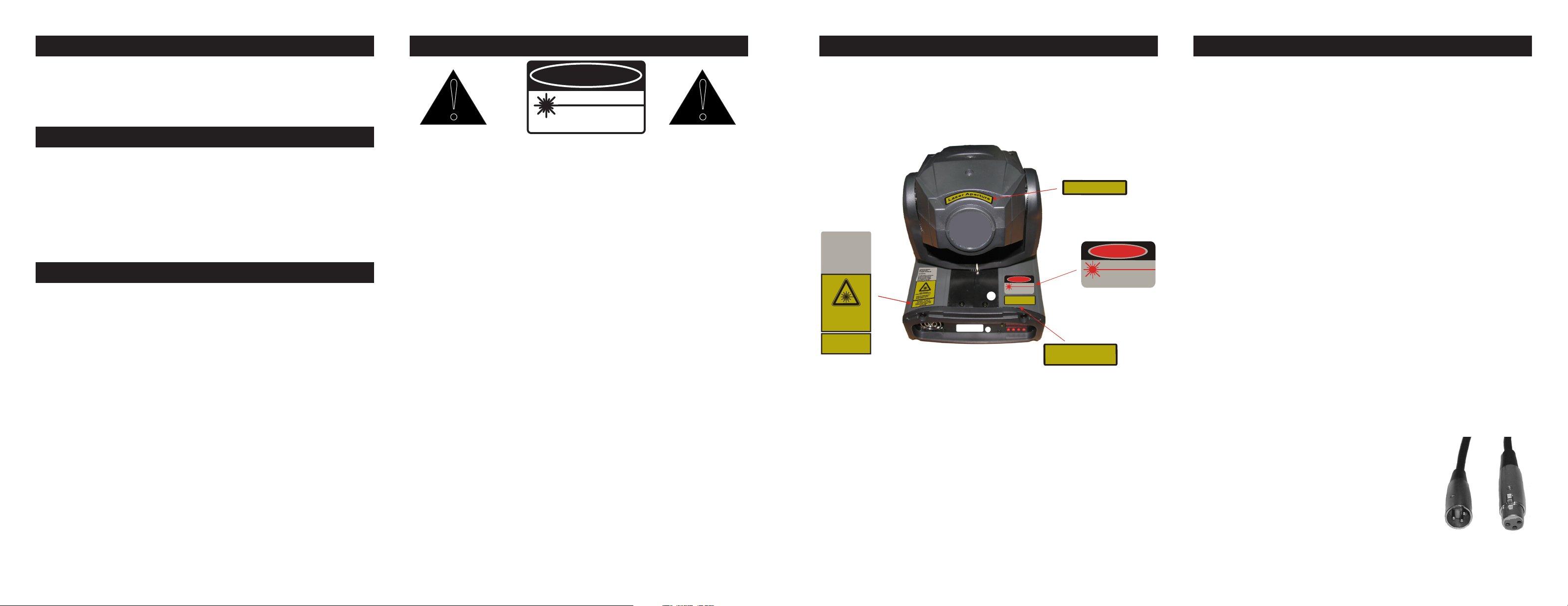
DANGER
VISIBLE LASER RADIATION
-AVOID DIRECT EYE EXPOSURE
LASER DIODE
WAVELENGTH : 635~650 nm
Max Output : <4.9mW
Class IIIa Laser Product
!
!
DA N G E R
VI SI BL E L AS ER RA DIAT IO N
-AV OID D IR E CT EYE EX PO SU R E
WAV EL EN GT H : 532n m/GR E EN
: 650 nm/RE D
Max . Output : <4. 9mW
CL AS S III a LAS E R P RO DUC T
CO MPL IE S WI TH C FR 1040. 10 AND 10 40. 11
L
a
s
e
r
A
p
e
t
u
r
e
r
C AUTION - CL ASS 3R
LASER RADIATION WHEN OPEN
AVOID DIREC T EYE EX POSURE
Americ an D J Supply, Inc.
4295 Charte r Street
Los Ange les. C A 9005 8 USA
Man ufac tured :
Co mplie swith FDA p erform anc e
stand ards fo rl ase rp roduc ts
with the exc eptio n of devia tion pursua nt to la ser Notic e
No.5 0,da ted J uly 26, 2001
LASER RADI ATION
AVOID DI REC TEYE EXPO SURE
CLA SS3 R LASER PRO DUCT
4.9 mW m ax C W Diode
IEC /EN 608 25-1 ,ed 1.2
CA UTION - C LASS 3 R
LASER R ADIATION WHEN
OPEN AVOID DIRE CT EYE
EXPO SURE
CAUTION -C LASS 3R
LASERR ADIATION WHENO PEN
AVOID DIRECT EYEEX POSURE
DA NG ER
VISIB LEL ASER RAD IATION
-AVOID DIRE CTE YE EXPO SURE
WAVELE NGTH :532nm /GREE N
:650nm /RED
Max.O utput:<4 .9mW
CLASS IIIa LASER PR ODUCT
COMPL IESW ITHC FR104 0.10AN D1040.1 1
QC
PAS S
QC
PAS S
X-Move Laser Laser Warninig Labels X-Move Laser Set Up
Please carefully read and understand the instructions in this manual
thoroughly before attempting to operate this unit. These instructions
contain important safety information regarding the use and maintenance of this unit. Please keep this manual with the unit, for future
reference.
X-Move Laser Features
• 4.9mW Green Laser Diode
• 6 Channel DMX Control
• 3 Operating Modes - Sound Active, Show Mode, & DMX Control
• Fan Cooled
• Digital Display for Address and Function Setting
• Multiple Patterns
• UC3 Controller (Not Included)
• 4 Preprogrammed Shows
X-Move Laser Warranty Registration
The X-Move Laser carries a 90 day limited warranty. Please fill out the
enclosed warranty card to validate your purchase. All returned service
items whether under warranty or not, must be freight pre-paid and
accompany a return authorization (R.A.) number. If the unit is under
warranty you must provide a copy of your proof of purchase invoice.
Please contact American DJ® customer support for a R.A. number.
Power Supply: Before plugging your unit in, be sure the source volt-
age in your area matches the required voltage for your American DJ®
X-Move Laser.™ The American DJ® X-Move Laser™ is available in a
120v and 220v version. Because line voltage may vary from venue to
venue, you should be sure your unit voltage matches the wall outlet
voltage before attempting to operate you xture. Also be sure to only
Safety Issues: This unit may “pop” the breaker if the maximum allotted
load of 2 amps is reached.
• To reduce the risk of electrical shock or re, do not expose this unit
rain or moisture.
• Do not spill water or other liquids into or on to your unit.
• Do not attempt to remove or break off the ground prong from the
electrical cord. This prong is used to reduce the risk of electrical
shock and re in case of an internal short. Do not attempt to oper-
ate this unit if the power cord has been frayed or broken.
• Disconnect from main power before making any type of connection.
• Do not remove the cover under any conditions. There are no user
serviceable parts inside.
• Always be sure to mount this unit in an area that will allow proper
ventilation. Allow about 6” (15cm) between this device and a wall.
• Do not attempt to operate this unit, if it becomes damaged.
• This unit is intended for indoor use only, use of this product out doors voids all warranties.
• During long periods of non-use, disconnect the unit’s main power.
• Always mount this unit in safe and stable matter.
• Power cords should be routed so they are not likely to be walked
on, pinched by items placed upon or against them.
• Cleaning -The fixture should be cleaned only as recommended by
the manufacturer. See page 18 for cleaning details.
• Heat -The appliance should be situated away from heat sources
such as radiators, heat registers, stoves, or other appliances
(including amplifiers) that produce heat.
• The fixture should be serviced by qualified service personnel when:
A. The power-supply cord or the plug has been damaged.
B. Objects have fallen, or liquid has been spilled into the unit.
C. The unit has been exposed to rain or water.
D. The unit does not appear to operate normally or exhibits a
marked change in performance.
©American DJ® - www.americandj.com - X-Move Laser Instruction Manual Page 4©American DJ® - www.americandj.com - X-Move Laser Instruction Manual Page 3
©American DJ® - www.americandj.com - X-Move Laser Instruction Manual Page 5
use the included I.E.C. power cable supplied with the unit, this cable
matches the voltage and current requirements of the unit.
DMX-512: DMX is short for Digital Multiplex. This is a universal pro-
tocol used by most lighting and controller manufactures as a form of
communication between intelligent fixtures and controllers. A DMX
controller sends DMX data instructions from the controller to the fixture. DMX data is sent as serial data that travels from fixture to fixture
via the DATA “IN” and DATA “OUT” XLR terminals located on all DMX
fixtures (most controllers only have a DATA “OUT” terminal).
DMX Linking: DMX is a language allowing all makes and models of
different manufactures to be linked together and operate from a single controller, as long as all xtures and the controller are DMX compliant. To ensure proper DMX data transmission, when using several
DMX fixtures try to use the shortest cable path possible. The order
in which fixtures are connected in a DMX line does not influence the
DMX addressing. For example; a fixture assigned a DMX address of 1
may be placed anywhere in a DMX line, at the beginning, at the end,
or anywhere in the middle. Therefore, the first fixture controlled by the
controller could be the last fixture in the chain. When a fixture is assigned a DMX address of 1, the DMX controller knows to send DATA
assigned to address 1 to that unit, no matter where it is located in the
DMX chain.
Data Cable (DMX Cable) Requirements (For
DMX and Master/Slave Operation): The X-Move
Laser™ can be controlled via DMX-512 protocol.
The X-Move Laser™ is be a six channel DMX unit.
The DMX address is set electronically using the
controls on the rear panel of the unit. Your unit and
your DMX controller require a approved DMX-512
110 Ohm Data cable for data input and data output
(Figure 1). We recommend Accu-Cable DMX cables. If you are making
©American DJ® - www.americandj.com - X-Move Laser Instruction Manual Page 6
Figure 1
Page 3

X-Move Laser Set Up X-Move Laser Set Up
DMX512 IN
3-PIN XLR
REMOTE
CONTROL
INPUT
POWER
INPUT OUTPUT
SOUND
REMOTE
CONTROL
INPUT
POWER
INPUT OUTPUT
SOUND
REMOTE
CONTROL
INPUT
POWER
INPUT OUTPUT
DMX512
DMX+,DMX-,COMMON
1
2
3
Terminatio n reduce s signal errors a nd
avo ids signal trans mis sion probl ems
and interference . It is always advisable
to connect a DMX terminal, (Resistance
120 Ohm 1/4 W) between PIN 2 (DMX-)
and PIN 3 (DMX +) of the last fixture.
1
2
3
1
2
3
DMX +
DMX -
COMMON
DMX512 OUT
3-PIN XLR
POWER
SOUND
REMOTE
CONTROL
INPUT
POWER
INPUT OUTPUT
1
2
3
Terminatio n reduce s signal errors a nd
avo ids signal trans mis sion probl ems
and interference . It is always advisable
to connect a DMX terminal, (Resistance
120 Ohm 1/4 W) between PIN 2 (DMX-)
and PIN 3 (DMX +) of the last fixture.
X-Move Laser™ System Menu X-Move Laser™ System Menu Chart
your own cables, be sure to use standard 110-120 Ohm shielded cable
(This cable may be purchased at almost all professional sound and
lighting stores). Your cables should be made with a male and female
XLR connector on either end of the cable. Also remember that DMX
cable must be daisy chained and cannot be split.
Notice: Be sure to follow gures two and three when making your own
cables. Do not use the ground lug on the XLR connector. Do not connect the cable’s shield conductor to the ground lug or allow the shield
conductor to come in contact with the XLR’s outer casing. Grounding
the shield could cause a short circuit and erratic behavior.
Special Note: Line Termination.
used, you may need to use a terminator on the last unit to avoid erratic
behavior. A terminator is a 110-120 ohm 1/4 watt resistor which is connected between pins 2 and 3 of a male XLR connector (DATA + and
DATA -). This unit is inserted in the female XLR connector of the last
unit in your daisy chain to terminate the line. Using a cable terminator
(ADJ part number Z-DMX/T) will decrease the possibilities of erratic
behavior.
XLR Male Socket
1 Ground
Figure 3
2 Cold
3 Hot
2 Cold
XLR Female Socket
Figure 2
XLR Pin Conguration
1 Ground
3 Hot
When longer runs of cable are
Pin 1 = Ground
Pin 2 = Data Compliment (negative)
Pin 3 = Data True (positive)
Figure 4
5-Pin XLR DMX Connectors.
Some manufactures use 5-pin DMX-
512 data cables for DATA transmission in place of 3-pin. 5-pin DMX
xtures may be implemented in a 3-pin DMX line. When inserting stan-
dard 5-pin data cables in to a 3-pin line a cable adaptor must be used,
these adaptors are readily available at most electric stores. The chart
below details a proper cable conversion.
3-Pin XLR to 5-Pin XLR Conversion
Conductor 5-Pin XLR Male (In)3-Pin XLR Female (Out)
Ground/Shield
Data Compliment (- signal)
Data True (+ signal)
Pin 1
Pin 2
Pin 3
Not Used
Not Used
©American DJ® - www.americandj.com - X-Move Laser Instruction Manual Page 8©American DJ® - www.americandj.com - X-Move Laser Instruction Manual Page 7 ©American DJ® - www.americandj.com - X-Move Laser Instruction Manual Page 9 ©American DJ® - www.americandj.com - X-Move Laser Instruction Manual Page 10
Pin 1
Pin 2
Pin 3
Pin 4 - Do Not Use
Pin 5 - Do Not Use
System Menu: When making adjustments you can press
ENTER to conrm your setup or you can wait 8 seconds for
automatic setup. To exit without making any adjustments
press the MENU button.
ADDR - DMX Address Setting.
1. Tap the either the MENU, UP, or DOWN buttons until “ADDR”
is displayed, press ENTER.
2. The current address will now be displayed and ashing.
Press the UP or DOWN buttons to nd your desired address.
Press ENTER to set your desired DMX address.
SHND - This will let you choose one of the four prepro-
grammed shows. See show descriptions below.
1. Tap the either the MENU button until “SHND” is displayed,
press ENTER. Either “SH 1”, “SH 2”, “SH 3” or “SH 4” will be displayed.
2. Tap the UP or DOWN buttons to nd you desired show and
then press ENTER to conm and exit.
SHOWS:
Show 1 - For xtures placed on the oor, the tilt movement
angle is 210°
Show 2 - For fixtures fixed to the ceiling or truss, the tilt movement angle is 90°.
Show 3 - For fixtures placed on a table. The beam is projected
at the audience’s direction; i.e. in front of the stage. Pan move-
ment angle (left to right to left) is 160°. Tilt movement angle is
90°.
Show 4 - For fixtures fixed to the ceiling. The beam is projected
at the audience’s direction; i.e. in front of the stage. Pan move-
ment angle (left to right to left) is 160°. Tilt movement angle is
90°.
Page 4

X-Move Laser™ System Menu X-Move Laser™ System Menu X-Move Laser™ System Menu
2. To activate the Pan inversion tap the UP or DOWN buttons
SLND - This will let you set unit as a master or slave in a
master/slave conguration.
1. Tap the MENU button until “SLND” is displayed, press
ENTER. Either “SL 1” or “SL 2” will be displayed.
2. Tap the UP or DOWN buttons until your desired setting is
displayed, press ENTER to conm.
NOTE: In a Master/Slave conguration you can make one
xture the Master and then set the next xture to “SL 2”, the
xtures will now have contrast movement to each other.
SOUN - Sound Active mode.
1. Tap the MENU button until “SOUN” is displayed, press
ENTER.
2. The display will show either “ON” or “OFF”. Press the UP or
DOWN buttons to select “ON” to activate sound active mode, or
“OFF” to deactivate sound active mode.
3. Press ENTER to conrm.
until “I” is displayed, press ENTER to conm. To deactivate Pan
inversion, select “NO” and press Enter.
I TLT - Tilt Inversion
1. Tap the MENU button until “I TLT” is displayed, press ENTER.
Either “NO” or “I” will be displayed.
2. To activate the Tilt inversion tap the UP or DOWN buttons
until “I” is displayed, press ENTER to conm. To deactivate Tilt
inversion, select “NO” and press Enter.
LED - With this function you can have the LED display
turn off after 10 seconds.
1. Tap the MENU button until “LED” is displayed, press ENTER.
2. The display will show either “ON” or “OFF”. Press the UP or
DOWN buttons to select “ON” to keep the LED display on at
all times, or “OFF” to switch to have the LED display switch off
after 10 seconds.
3. Press ENTER to conrm.
FHRS - With this function you can display the running time
of the xture.
1. Tap the MENU button until “FHRS” is displayed, press
ENTER.
2. The display shows the running time of the unit. Press MENU
to exit.
VER - With this function you can display the version soft-
ware of the unit.
1. Tap the MENU button until “VER” is displayed, press ENTER.
2. The display will now display the version of software. Press
MENU to exit.
RSET - Use this function to reset the unit.
1. Tap the MENU button until “RSET” is displayed, press ENTER.
2. The xture will now reset
BLND - Blackout or Stand by mode.
1. Tap the MENU button until “BLND” is displayed, press
ENTER. Either Yes or No will be displayed.
2. To activate Blackout tap the UP or DOWN buttons until “Yes”
is displayed, press ENTER to conm. The xture will now be in
Blackout mode. To deactivate Blackout mode, select “No” and
press Enter.
I PAN - Pan Inversion
1. Tap the MENU button until “I PAN” is displayed, press ENTER.
Either “NO” or “I” will be displayed.
DISP - This function will reverse the display 180º.
1. Tap the MENU button until “DISP” is displayed, press ENTER.
2. Press ENTER to “ip” the display. Press ENTER to “ip” it
again. Press ENTER when you have made your desired setup.
TEST - This function will run a self test program. The test
program will test pan/tilt movement and colors.
1. Tap the MENU button until “TEST” is displayed, press ENTER.
2. The xture will now run a self test.
X-Move Laser™ Operation
Operating Modes: The X-Move Laser™ can operate in three
different modes. In each mode you can run the fixture as a
stand alone fixute or in a master/slave confiugration. This next
section will detail the differences in the operating modes.
• Sound Active mode -
The fixture will react to sound, chasing through the built-in programs.
• Show mode -
The fixture will run one of four shows that you choose.
• DMX control mode -
This function will allow you to control each individual fixtures traits
with a standard DMX-512 controller such as the Elation® Show
Designer.
Master-Slave Operation This function will allow you to link up to 16
units together and operate without a controller. The units will be sound
activated. In Master-Slave operation one unit will act as the controlling
unit and the others will react to the controlling units programs. Any unit
can act as a Master or as a Slave.
1. Using approved DMX data cables, daisy chain your units togeth-
er via the XLR connector on the rear of the units. Remember the
Male XLR connector is the input and the Female XLR connector
is the output. The rst unit in the chain (master) will use the female
XLR connector only - The last unit in the chain will use the male
XLR connector only. For longer cable runs we suggest a termina-
tor at the last fixture.
2. On the Master unit find your desired show and set that show by
pressiing the ENTER button.
3. On the slave units tap the MENU button until “SLND” is dis-
played, and Press ENTER. Choose either “SL 1” or “SL 2” and
press ENTER. Please see page 11 for more info.
4. The slave units will now follow the Master unit.
Universal DMX Control: This function allows you to use a Elation®
universal DMX-512 controller to control the chases and patterns,
dimmer and strobe. A DMX controller allows you to create unique
programs tailored to your individual needs.
1. The X-Move Laser™ is a six DMX channel DMX fixture. See
™
©American DJ® - www.americandj.com - X-Move Laser Instruction Manual Page 14©American DJ® - www.americandj.com - X-Move Laser Instruction Manual Page 13©American DJ® - www.americandj.com - X-Move Laser Instruction Manual Page 12©American DJ® - www.americandj.com - X-Move Laser Instruction Manual Page 11
Page 5

X-Move Laser™ Operation
Stand B y
Blac kou t on
Function
disc ontinu ous
line effect
Show m ode
1-4
Mode
LED off
LED o n
Select Pattern
LED b linking
X-Move Laser™ DMX Traits
X-Move Laser™ DMX Traits
X-Move Laser™ Fuse Replacement
pages 16-17 for detailed description of the DMX values and traits.
2. To control your fixture in DMX mode, follow the set-up procedures
on pages 5-7 as well as the set-up specifications that are includ ed with your DMX controller.
3. Use the controller’s faders to control the various DMX fixture traits.
4. This will allow you to create your own programs.
5. Follow the instruction on page 8 to set the DMX address.
6. For longer cable runs (more than a 100 feet) use a terminator on
the last fixture.
7. For help operating in DMX mode consult the manual included
with your DMX controller.
Sound Active Mode: This mode allows either single unit or several
units linked together, to run to the beat of the music.
1. Tap the MENU button until “SOUN” is displayed, and press
ENTER.
2. Tap the UP or DOWN buttonS until you nd your desired show,
and press ENTER.
3. The optional UC3 Controller (not included) may be used to con trol different functions including blackout.
Show Mode: This mode allows either a single unit or several units
linked together, to run one of four shows that you choose.
1. Tap the MENU button until “SHND” is displayed, and press
ENTER.
2. Tap the UP or DOWN buttons until you nd your desired show,
and press ENTER.
X-Move Laser™ UC3 Control
The optional UC3 Controller (not included) may be used to con-
trol different functions including blackout.
©American DJ® - www.americandj.com - X-Move Laser Instruction Manual Page 15 ©American DJ® - www.americandj.com - X-Move Laser Instruction Manual Page 16
Channel Value Function
1 0 - 255 PAN
2 0 - 255 TILT
3 LASER PATTERNS
0 - 12 PATTERN 1
13 - 24 PATTERN 2
25 - 36 PATTERN 3
37 - 48 PATTERN 4
49 - 60 PATTERN 5
61 - 72 PATTERN 6
73 - 85 PATTERN 7
86 - 97 PATTERN 8
98 - 109 PATTERN 9
110 - 121 PATTERN 10
122 - 133 PATTERN 11
134 - 145 PATTERN 12
146 - 157 PATTERN 13
158 - 170 PATTERN 14
171 - 182 PATTERN 15
183 - 194 PATTERN 16
195 - 206 PATTERN 17
207 - 218 PATTERN 18
219 - 230 PATTERN 19
231 - 242 PATTERN 20
243 - 255 PATTERN 21
4 LASER MOVEMENT
0 - 15 LASER OFF
16 - 239 LASER PATTER MOVEMENT
FAST - SLOW
240 - 255 LASER ON/NO MOVEMENT
5 MOVING HEAD MOVEMENT
0 - 7 NO FUNCTION
8 - 28 MOVEMENT 1
29 - 49 MOVEMENT 2
50 - 70 MOVEMENT 3
Channel Value Function
5 MOVING HEAD MOVEMENT
71 - 91 MOVEMENT 4
92 - 112 MOVEMENT 5
113 - 133 MOVEMENT 6
134 - 154 MOVEMENT 7
155 - 175 MOVEMENT 8
176 - 196 MOVEMENT 9
197 - 217 MOVEMENT 10
218 - 238 MOVEMENT 11
239 - 255 MOVEMENT 12
6 0 - 255 MOVEMENT SPEED FAST - SLOW
©American DJ® - www.americandj.com - X-Move Laser Instruction Manual Page 17
Locate and remove the unit’s power cord. Once the cord has been
removed located the fuse holder located inside the power socket.
Insert a flat-head screw driver into the power socket and gently pry
out the fuse holder. Remove the bad fuse and replace with a new one.
The fuse holder has a built-in socket for a spare fuse be sure not to
confuse the spare fuse with active fuse.
X-Move Laser Cleaning
Fixture Cleaning: Due to fog residue, smoke, and dust cleaning
the internal and external lenses should be carried out periodically to
optimize light output.
1. Use normal glass cleaner and a soft cloth to wipe down the out-
side casing.
2. Clean the external optics with glass cleaner and a soft cloth every
20 days.
3. Always be sure to dry all parts completely before plugging the
unit back in.
Cleaning frequency depends on the environment in which the fixture
operates (I.e. smoke, fog residue, dust, dew). In heavy use we recommend cleaning on a monthly basis. Periodic cleaning will ensure longevity, and crisp beam output.
X-Move Laser™ Trouble Shooting
Trouble Shooting: Listed below are a few common problems that
you may encounter, with solutions.
No light output from the unit;
1. Be sure you have connected your unit into a standard 120v wall
outlet.
2. Be sure the external fuse has not blown. The fuse is located on
the rear panel of the unit.
3. Be sure the fuse holder is completely and properly seated.
Unit does not respond to sound;
1. Low frequencies (bass) should cause the unit to react to sound.
Tapping on the microphone, quiet or high pitched sounds may
not activate the unit.
©American DJ® - www.americandj.com - X-Move Laser Instruction Manual Page 18
Page 6

MANUFACTURER’S LIMITED WARRANTY
A. American DJ, Inc. hereby warrants, to the original purchaser, American DJ and American
Audio products to be free of manufacturing defects in material and workmanship for a prescribed
period from the date of purchase (see specic warranty period on reverse). This warranty shall be
valid only if the product is purchased within the United States of America, including possessions
and territories. It is the owner’s responsibility to establish the date and place of purchase by acceptable evidence, at the time service is sought.
B. For warranty service you must obtain a Return Authorization number (RA#) before
sending back the product. Contact American DJ, Inc. Service Department at 800-322-6337. Send
the product only to the American DJ, Inc. factory. All shipping charges must be pre-paid. If the
requested repairs or service (including parts replacement) are within the terms of this warranty,
American DJ, Inc. will pay return shipping charges only to a designated point within the United
States. If the entire instrument is sent, it must be shipped in it’s original package. No accessories
should be shipped with the product. If any accessories are shipped with the product, American DJ,
Inc. shall have no liability whatsoever for loss of or damage to any such accessories, nor for the
safe return thereof.
C. This warranty is void if the serial number has been altered or removed; if the product is
modied in any manner which American DJ, Inc. concludes, after inspection, affects the reliability
of the product; if the product has been repaired or serviced by anyone other than the American DJ,
Inc. factory unless prior written authorization was issued to purchaser by American DJ, Inc.; if the
product is damaged because not properly maintained as set forth in the instruction manual.
D. This is not a service contract, and this warranty does not include maintenance, cleaning
or periodic check-up. During the period specied above, American DJ, Inc. will replace defective parts at its expense with new or refurbished parts, and will absorb all expenses for warranty
service and repair labor by reason of defects in material or workmanship. The sole responsibility
of American DJ, Inc. under this warranty shall be limited to the repair of the product, or replacement thereof, including parts, at the sole discretion of American DJ. All products covered by this
warranty were manufactured after January 1, 1990, and bear identifying marks to that effect.
E. American DJ, Inc. reserves the right to make changes in design and/or improvements
upon its products without any obligation to include these changes in any products theretofore
manufactured. No warranty, whether expressed or implied, is given or made with respect to any
accessory supplied with products described above. Except to the extent prohibited by applicable
law, all implied warranties made by American DJ, Inc. in connection with this product, including
warranties of merchantability or tness, are limited in duration to the warranty period set forth
above. And no warranties, whether expressed or implied, including warranties of merchantability
or tness, shall apply to this product after said period has expired. The consumer’s and/or Dealer’s
sole remedy shall be such repair or replacement as is expressly provided above; and under no
circumstances shall American DJ, Inc. be liable for any loss or damage, direct or consequential,
arising out of the use of, or inability to use, this product.
This warranty is the only written warranty applicable to American DJ and American Audio
Products and supersedes all prior warranties and written descriptions of warranty terms and
conditions heretofore published.
MANUFACTURER’S LIMITED WARRANTY PERIODS:
• All American Audio Products = 1-year (365 day) Limited Warranty (except V-Plus Series Ampliers)
• All American Audio V-Plus Series Ampliers = 3-year (1095 day) Limited Warranty
• American DJ Lighting and American DJ Branded Products = 1-year (365 day) Limited Warranty
(Such as: Special Effect Lighting, Intelligent Lighting, UV lighting, Strobes, Fog Machines, Bubble
Machines, Mirror Balls, Par Cans, Trussing, Lighting Stands etc. excluding Laser Products, lamps,
and Star Tec Series)
• American DJ Laser Products and Star Tec Products = 90-Day Limited Warranty
• American DJ L.E.D. Products = 3-year (1095 day) Limited Warranty (excluding motors which
have a 1-year (365 day Limited Warranty)
©American DJ® - www.americandj.com - X-Move Laser Instruction Manual Page 19
X-Move Laser Specifications X-Move Laser Warranty
Model: X-Move Laser
Voltage*: 120v~60Hz / 230v~50Hz
Lasers: 4.9mW Green Diode
Dimensions: 8”(L) x 7.5”(W) x 11.25”(H)
203.2mm x 190.5mm x 285.75mm
Colors: Green
Weight: 10 Lbs. / 4.5 kgs.
Fuse: 1 Amp (120v & 230v)
Duty Cycle: None
DMX: 6 DMX Channels
Sound Active: Yes
Working Position: Any Safe, Secure Position
Warranty: 90 Days
*Voltage is preset at the factory and can not be changed by the user.
Please Note: Specications and improvements in the design
of this unit and this manual are subject to change without any
prior written notice.
American DJ®
American DJ World Headquarters:
6122 S. Eastern Ave. Los Angeles, CA 90040 USA
Tel: 323-582-2650 / Fax: 323-725-6100
Web: www.americandj.com / E-mail: info@americandj.com
 Loading...