

Page 1
CONTOUR
User Instructions
Page 2
©2018 ADJ Products, LLC all rights reserved. Information, specications, diagrams, images, and
with the included instructions, may cause harmful interference to radio communications. However, there is
instructions herein are subject to change without notice. ADJ Products, LLC logo and identifying
product names and numbers herein are trademarks of ADJ Products, LLC. Copyright protection
claimed includes all forms and matters of copyrightable materials and information now allowed by
statutory or judicial law or hereinafter granted. Product names used in this document may be
trademarks or registered trademarks of their respective companies and are hereby acknowledged.
All non-ADJ Products, LLC brands and product names are trademarks or registered trademarks of
their respective companies.
ADJ Products, LLC and all aliated companies hereby disclaim any and all liabilities for property,
equipment, building, and electrical damages, injuries to any persons, and direct or indirect economic
loss associated with the use or reliance of any information contained within this document, and/or as
a result of the improper, unsafe, unsucient and negligent assembly, installation, rigging, and operation of this product.
FCC STATEMENT
This device complies with Part 15 of the FCC Rules. Operation is subject to the following two conditions:
(1) this device may not cause harmful interference, and (2) this device must accept any interference
received, including interference that may cause undesired operation.
FCC RADIO FREQUENCY INTERFERENCE WARNINGS & INSTRUCTIONS
This product has been tested and found to comply with the limits as per Part 15 of the FCC Rules. These
limits are designed to provide reasonable protection against harmful interference in a residential installation. This device uses and can radiate radio frequency energy and, if not installed and used in accordance
no guarantee that interference will not occur in a particular installation. If this device does cause harmful
interference to radio or television reception, which can be determined by turning the device off and on, the
user is encouraged to try to correct the interference by one or more of the following methods:
· Reorient or relocate the device.
· Increase the separation between the device and the receiver.
· Connect the device to an electrical outlet on a circuit different from which the radio receiver is
connected.
· Consult the dealer or an experienced radio/TV technician for help.
DOCUMENT VERSION
Please check www.adj.com for the latest revision/update of this guide.
Date
01/04/19
Document
Version
1 1.2
Software
Version
>
DMX
Channel
Mode
3/7/9 Initial Release
Notes
Europe Energy Saving Notice
Energy Saving Matters (EuP 2009/125/EC)
Saving electric energy is a key to help protecting the enviroment. Please turn o all electrical products when
they are not in use. To avoid power consumption in idle mode, disconnect all electrical equipment from power
when not in use. Thank you!
Page 3
Contour Table of Contents
Introduction
Features I Warranty I Installation
Safety Guidelines
DMX Setup
DMX Addressing
Overview
System Menu
Operating Instructions
Master-Slave Conguration
ADJ UC Laser IR/Airstream IR Control
DMX Channel Modes
3
4
5
6
8
9
10
11
13
14
15
Dimensional Drawings
Fuse Replacement I Trouble Shooting I Cleaning
Limited Warranty (USA Only)
Specications
16
17
18
19
ADJ Products, LLC - www.adj.com - Contour User Manual Page 2
Page 4

Contour Introduction
Unpacking: Thank you for purchasing the Contour by ADJ Products, LLC. Every Contour has been
thoroughly tested and has been shipped in perfect operating condition. Carefully check the shipping
carton for damage that may have occurred during shipping. If the carton appears to be damaged,
carefully inspect your xture for any damage and be sure all accessories necessary to operate the unit
has arrived intact. In the case damage has been found or parts are missing, please contact our toll free
customer support number for further instructions. Do not return this unit to your dealer without rst
contacting customer support.
Introduction: The ADJ Contour is a DMX intelligent LED moonflower fixture. The Contour can operate
as a stand alone fixture or in a Master/Slave set up. The Contour has three operating modes; show
mode, sound active mode, & DMX controlled. This fixture is suitable for theaters, studios, retail stores,
and other similar locations. For best results use fog or special effects smoke to enhance the beams
projections.
These instructions contain important safety information regarding the use and maintenance of this
system. Please keep this manual with the system, for future reference.
Customer Support: Contact ADJ Service for any product related service and support needs. Also visit
forums.adj.com with questions, comments or suggestions.
Parts: To purchase parts online visit http://parts.adj.com
ADJ SERVICE USA - Monday - Friday 8:00am to 4:30pm PST
Voice: 323-582-2650 | Fax: 323-832-2941 | support@adj.com
ADJ SERVICE EUROPE - Monday - Friday 08:30 to 17:00 CET
Voice: +31 45 546 85 60 | Fax: +31 45 546 85 96 | support@adj.eu
WARNING!
To prevent or reduce the risk of electrical shock or re, do not expose this unit to rain or moisture.
CAUTION!
There are no user serviceable parts inside this unit. Do not attempt any repairs yourself, doing so will
void your manufactures warranty. In the unlikely event your unit may require service please contact
ADJ Products, LLC.
PLEASE recycle the shipping carton when ever possible.
ADJ Products, LLC - www.adj.com - Contour User Manual Page 3
Page 5
Contour Features
• Three Operating Modes
• Electronic Dimming 0-100%
• DMX-512 Protocol | 3pin DMX In/Out Connections
• Three DMX Modes: 3 / 7 / 9
• ADJ UC Laser IR and Airstream IR compatible (Transmitter Not Included)
• Multiple Unit Power Linking
Included:
• 1 x Power Cord
• 1 x ADJ UC Laser IR Remote Control
Contour Warranty Registration
The Contour carries a 2 year (730 Days) limited warranty. Please fill out the enclosed warranty card to
validate your purchase. All returned service items whether under warranty or not, must be freight prepaid and accompany a return authorization (R.A.) number. The R.A. number must be clearly written
on the outside of the return package. A brief description of the problem as well as the R.A. number
must also be written down on a piece of paper included in the shipping carton. If the unit is under
warranty, you must provide a copy of your proof of purchase invoice. You may obtain a R.A. number
by contacting our customer support team on our customer support number. All packages returned to
the service department not displaying a R.A. number on the outside of the package will be returned to
the shipper.
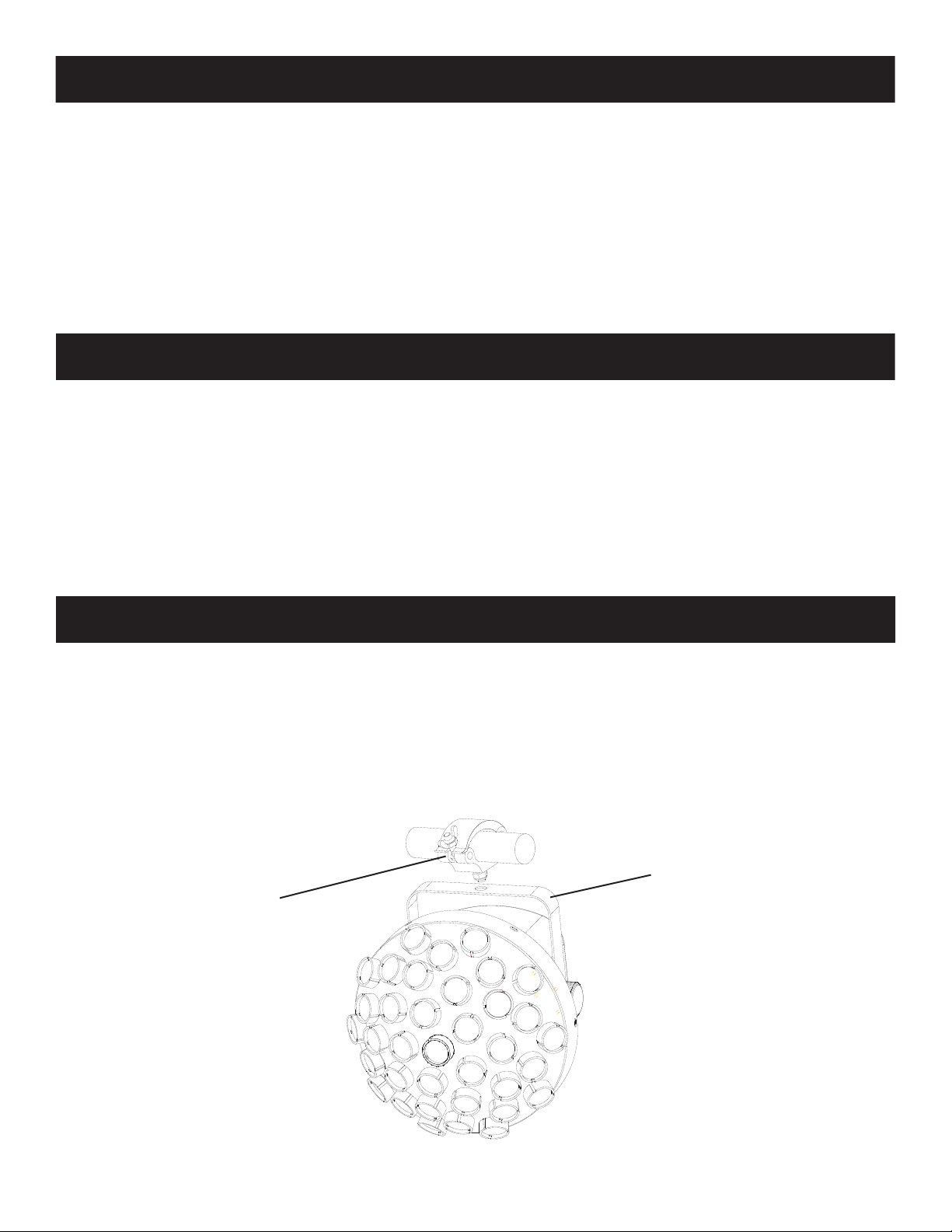
Contour Installation
Fixtures should be mounted using a mounting clamp (not provided), axing it to the mounting
bracket that is provided with the unit. Always ensure that the xture is rmly xed to avoid vibration
and slipping while operating. Always ensure that the structure to which you are attaching the unit is
secure and is able to support a weight of 10 times the unit’s weight. Also, always use a safety cable
that can hold 12 times the weight of the unit when installing the xture. The equipment must be
installed by a professional, and it must be installed in a place where it is out of the reach of people’s
grasp.
Hanging Bracket
Mounting Clamp
ADJ Products, LLC - www.adj.com - Contour User Manual Page 4
Page 6

Contour Safety Guidelines
For Your Own Personal Safety, Please Read and Understand This Manual Completely Before
You Attempt To Install Or Operate This Unit!
• To reduce the risk of electrical shock or re, do not expose this unit rain or moisture
• Do not spill water or other liquids into or on to your unit.
• Be sure that the local power outlet match that of the required voltage for your unit.
• Do not attempt to operate this unit if the power cord has been frayed or broken.
• Do not attempt to remove or break o the ground prong from the electrical cord. This prong is used
to reduce the risk of electrical shock and re in case of an internal short.
• Disconnect from main power before making any type of connection.
• Do not remove the cover under any conditions. There are no user serviceable parts inside.
• Never operate this unit when it’s cover is removed.
• Always be sure to mount this unit in an area that will allow proper ventilation. Allow about 6”
(15cm) between this device and a wall.
• Do not attempt to operate this unit, if it becomes damaged.
• This unit is intended for indoor use only, use of this product outdoors voids all warranties.
• Always mount this unit in safe and stable matter.
• Power-supply cords should be routed so that they are not likely to be walked on or pinched by
items placed upon or against them, paying particular attention to cords at plugs, convenience
receptacles, and the point where they exit from the appliance.
• Cleaning -The fixture should be cleaned only as recommended by the manufacturer. See page 17
for cleaning details.
• Heat -This fixture should be situated away from heat sources such as radiators, heat registers,
stoves, or other appliances (including amplifiers) that produce heat.
• The fixture should be serviced by qualified service personnel when:
A. Objects have fallen, or liquid has been spilled into the appliance.
B. The appliance has been exposed to rain or water.
C. The appliance does not appear to operate normally or exhibits a marked change in performance.
ADJ Products, LLC - www.adj.com - Contour User Manual Page 5
Page 7

Contour DMX Set Up
REMOTE
CONTROL
INPUT
POWER
INPUT OUTPUT
SOUND
REMOTE
CONTROL
INPUT
POWER
INPUT OUTPUT
SOUND
REMOTE
CONTROL
INPUT
POWER
INPUT OUTPUT
DMX512
DMX+,DMX-,COMMON
1
2
3
Termination reduces signal errors and
avoids signal transmission problems
and interference. It is always advisable
to connect a DMX terminal, (Resistance
120 Ohm 1/4 W) between PIN 2 (DMX-)
and PIN 3 (DMX +) of the last fixture.
DMX-512: DMX is short for Digital Multiplex. This is a universal protocol used as a form of communication
between intelligent fixtures and controllers. A DMX controller sends DMX data instructions from the
controller to the fixture. DMX data is sent as serial data that travels from fixture to fixture via the DATA
“IN” and DATA “OUT” XLR terminals located on all DMX fixtures (most controllers only have a DATA
“OUT” terminal).
DMX Linking: DMX is a language allowing all makes and models of dierent manufactures to be
linked together and operate from a single controller, as long as all xtures and the controller are DMX
compliant. To ensure proper DMX data transmission, when using several DMX fixtures try to use
the shortest cable path possible. The order in which fixtures are connected in a DMX line does not
influence the DMX addressing. For example; a fixture assigned a DMX address of 1 may be placed
anywhere in a DMX line, at the beginning, at the end, or anywhere in the middle. When a fixture is
assigned a DMX address of 1, the DMX controller knows to send DATA assigned to address 1 to that
unit, no matter where it is located in the DMX chain.
Data Cable (DMX Cable) Requirements (For DMX Operation): The Contour can
be controlled via DMX-512 protocol and has 3 DMX channel modes. The DMX
address is set on the rear panel. The Contour requires a standard 3-pin XLR connector
for data input and data output (Figure 1), which are included on the included DMX
cables. If you are making your own cables, be sure to use standard 110-120 Ohm
shielded cable (This cable may be purchased at almost all pro lighting stores). Your
cables should be made with a male and female XLR connector on either end of
the cable. Also remember that DMX cable must be daisy chained and cannot be
split.
Figure 1
Notice: Be sure to follow gures 2 and 3 below when making your own cables. Do not use the ground
lug on the XLR connector. Do not connect the cable’s shield conductor to the ground lug or allow the
shield conductor to come in contact with the XLR’s outer casing. Grounding the shield could cause a
short circuit and erratic behavior.
XLR Male Socket
1 Ground
Figure 3
DMX512 OT
3-PIN XLR
2 Cold
3 Hot
1
3
2
COMMON
DMX +
DMX -
XLR Female Socket
2 Cold
1 Ground
3 Hot
1
3
2
DMX512 IN
3-PIN XLR
Figure 2
XLR Pin Conguration
Pin 1 = Ground
Pin 2 = Data Compliment (negative)
Pin 3 = Data True (positive)
ADJ Products, LLC - www.adj.com - Contour User Manual Page 6
Page 8

Contour DMX Set Up
POWER
SOUND
REMOTE
CONTROL
INPUT
POWER
INPUT OUTPUT
and PIN 3 (DMX +) of the last fixture.
Special Note: Line Termination.
When longer runs of cable are used, you may need to use a
terminator on the last unit to avoid erratic behavior. A terminator is a 110-120 ohm 1/4 watt resistor
which is connected between pins 2 and 3 of a male XLR connector (DATA + and DATA -). This unit is
inserted in the female XLR connector of the last unit in your daisy chain to terminate the line. Using a
cable terminator (ADJ part number Z-DMX/T) will decrease the possibilities of erratic behavior.
Termination reduces signal errors and
1
3
avoids signal transmission problems
and interference. It is always advisable
2
to connect a DMX terminal, (Resistance
120 Ohm 1/4 W) between PIN 2 (DMX-)
Figure 4
5-Pin XLR DMX Connectors.
Some manufactures use 5pin DMX-512 data cables for DATA
transmission in place of 3pin. 5pin DMX xtures may be implemented in a 3-pin DMX line. When
inserting standard 5pin data cable in to a 3pin line a cable adaptor must be used, these adaptors are
readily available at most electric stores. The chart below details a proper cable conversion.
3-Pin XLR to 5-Pin XLR Conversion
Conductor 5pin XLR Male (In)3pin XLR Female (Out)
Ground/Shield
Pin 1
Pin 1
Data Compliment (- signal)
Data True (+ signal)
Not Used
Not Used
Pin 2
Pin 3
Pin 2
Pin 3
Do Not Use
Do Not Use
ADJ Products, LLC - www.adj.com - Contour User Manual Page 7
Page 9

Contour DMX Addressing
All xtures should be given a DMX starting address when using a DMX controller, so the correct xture
responds to the correct control signal. This digital starting address is the channel number from which
the xture starts to “listen” to the digital control signal sent out from the DMX controller. The assignment
of this starting DMX address is achieved by setting the correct DMX address on the digital control
display on the xture.
You can set the same starting address for all xtures or a group of xtures, or set dierent addresses
for each individual xture. Setting all xtures to the same DMX address will cause all xtures to react
in the same way, in other words, changing the settings of one channel will aect all the xtures
simultaneously.
If you set each xture to a dierent DMX address, each unit will start to “listen” to the channel number
you have set, based on the quantity of DMX channels of each xture. That means changing the settings
of one channel will only aect the selected xture.
In the case of the Contour, when in 3 Channel you should set the starting DMX address of the rst unit
to 1, the second unit to 4 (3 + 1), the third unit to 7 (4 + 3), and so on. (See chart below for more details.)
Channelmode
3 channels 1 4 7 10
7 channels 1 8 15 22
9 channels 1 10 19 28
Unit1
Address
Unit2
Address
Unit3
Address
Unit4
Address
ADJ Products, LLC - www.adj.com - Contour User Manual Page 8
Page 10

Contour Overview
LCD DISPLAY
CONTROL PANEL
(MENU/UP/DOWN/ENTER)
DMX IN
DMX OUT
SAFETY CABLE
RIGGING POINT
POWER OUT POWER IN &
FUSE SOCKET
ADJ Products, LLC - www.adj.com - Contour User Manual Page 9
Page 11

Contour System Menu
Main Menu Submenu Function
System
Menu
Addr
Chnd
Shnd
SLnd
LoSt
SP_A
SP_n
(001-512)
3CH
7CH
9CH
Set DMX Address
3 DMX Channel Mode
7 DMX Channel Mode
9 DMX Channel Mode
Sh 1- Sh 15
MASt
Shows 1-15
Master Setting
SL 1
Soun
Slave Setting
Sound Active Mode
When DMX Signal Is Lost
Auto
Auto Run Mode
When DMX Signal Is Lost
hoLd
bLAC
A.001-A.100
n.000 -n.100
DMX Setting Held
When DMX Signal Is Lost
Blackout
When DMX Signal Is Lost
Auto Show Run Speed
Slow-Fast
Motor Speed Low-Fast
SEnS
S000-S099
Sound Sensitivity
Adjustment
Manual Test for Color
MAnu
Co_1-Co_7
On
Macro
Backlight ON
LEd
oFF
On
Backlight OFF
Display Reverse ON
diSP
oFF
Display Reverse OFF
FhrS
vEr
dEFA
XXXH
U X.X
Total Running Hours
Current Software Version
Factory Default
Press ENTER To Restore
Factory Settings
ADJ Products, LLC - www.adj.com - Contour User Manual Page 10
Page 12

Contour Operating Instructions
System Menu & Display Lock: When making adjustments press ENTER to conrm your setup
then press and hold the MENU button for at least 3 seconds. To exit without making any
adjustments press the MENU button. The display will lock after 30 seconds, press the MENU
button for 3 seconds to unlock.
DMX ADDRESS SETTING - Select your desired DMX address.
1. Press the MENU button until “Addr” is displayed, and press ENTER.
2. The current address will now be displayed and ashing. Press the UP or DOWN buttons to nd
your desired address. Press ENTER to set your desired DMX address.
DMX CHANNEL MODE - Select your desired DMX channel mode.
1. Press the MENU button until “Chnd” is displayed, and press ENTER. The current DMX channel
mode will now be displayed.
2. Press the UP or DOWN buttons to nd your desired DMX channel mode and press ENTER to
conm and exit.
SHOW MODE - Show modes 1-15 (Factory programs). Show mode can run with or without
sound active mode active.
1. Press the MENU button until “Shnd” is displayed, and press ENTER.
2. “Sh X” will now be displayed, “X” representing a number between 0-4. Shows 1-4 are factory pro-
grams, while show “0” is random mode. Use the UP or DOWN buttons to nd your desired show.
3. When you have found your desired show press ENTER, then press and hold the MENU button for
at least 3 seconds to activate. After you have set your desired show, it can be changed at any time
using the UP or DOWN buttons.
MASTER-SLAVE SETUP - Set up master/slave conguration.
1. Press the MENU button until “SLnd” is displayed, and press ENTER. Either “MASt” or “SL 1” will
be displayed.
2. Press the UP or DOWN buttons until your desired setting is displayed, press ENTER to conm.
ADJ Products, LLC - www.adj.com - Contour User Manual Page 11
Page 13

Contour Operating Instructions
DMX LOST SIGNAL - This is a precaution mode. In the case that the DMX signal is lost, interrupted,
or power is lost. The operating mode selected in this set up is the running mode the xture will
automatically go into when the DMX signal is lost. You can also set this as the operating mode
you would like the unit to return to when power is applied.
1. Press the MENU button until “LoSt” is displayed, and press ENTER. Either “Soun”, “bLAC”, or
“Auto”, or “hoLd” will be displayed beneath.
• Soun - If the DMX signal is lost the xture will go into sound active mode.
• Auto - If the DMX signal is lost or power is applied, the unit will automatically run a built-in program.
• hoLd - If the DMX signal is lost or power is applied, the unit will automatically hold the last DMX setting.
• bLAC (Blackout) - If the DMX signal is lost or interrupted, the unit will automatically go into stand by
mode.
3. Press ENTER to conrm your desired set up.
SHOW MODE RUNNING SPEED - Adjust the running speed of an active show.
1. Press the MENU button until “SP_A” is displayed, and press ENTER. “A.XXX” will now be displayed. “XXX” represents the current running speed setting.
2. A number between 000-100 will be displayed. Press the UP or DOWN buttons to adjust the show
running speed. 000 being the slowest speed, and 100 being the fastest speed.
3. When you have found your desired setting press ENTER to conrm.
MOTOR RUNNING SPEED - Adjust the running speed of the motor.
1. Press the MENU button until “SP_n” is displayed, and press ENTER. “n.XXX” will now be displayed. “XXX” represents the current motor speed setting.
2. A number between 000-100 will be displayed. Press the UP or DOWN buttons to adjust the motor
running speed. 000 being the slowest speed, and 100 being the fastest speed.
3. When you have found your desired setting press ENTER to conrm.
SOUND SENSITIVITY - Adjust the sound sensitivity.
1. Press the MENU button until “SEnS” is displayed, and press ENTER.
2. A number between 000-099 will be displayed. Press the UP or DOWN buttons to adjust the sound
sensitivity. 0 being the least sensitive, and 099 being the most sensitive.
3. When you have found your desired setting press ENTER to conrm.
ADJ Products, LLC - www.adj.com - Contour User Manual Page 12
Page 14

Contour Operating Instructions
MANUAL TEST - Manually test the color macros.
1. Press the MENU button until “MAnu” is displayed, and press ENTER.
1. “CO_X” will be displayed. “X” represents the current displayed color number.
3. Press ENTER to conrm. To make you LED display reappear again press any button.
BACKLIGHT - Display will stay on at all times or can shut o after 10 seconds.
1. Press the MENU button until “LEd” is displayed, and press ENTER.
2. The display will show either “On” or “oFF”. Press the UP or DOWN buttons to select “On” to keep
the LED display on at all times, or “oFF” to switch to have the LED display switch o after 10 seconds.
3. Press ENTER to conrm. To reactivate the backlight press any button.
DISPLAY INVERSION - Allows you to “ip” the display 180º.
1. Press the MENU button until “dISP” is displayed, and press ENTER.
2. Press ENTER to “ip” the display. Press ENTER to “ip” it again.
TOTAL RUNNING TIME - Display the total running time (hours) of the unit.
1. Press the MENU button until “FhrS” is displayed, and press ENTER.
2. The running time of the xture will now be displayed. Press MENU to exit.
SOFTWARE VERSION - Display the current software version.
1. Press the MENU button until “vEr” is displayed, and press ENTER.
2. The current software version will now be displayed. Press MENU to exit.
DEFAULT MODE - Revert to default settings.
1. Press the MENU button until “dEFA” is displayed, and press ENTER.
Contour Master-Slave Configuration
Master-Slave Operation This function will allow you to link up to 16 units together and operate without
a controller. In a Master-Slave set up, one unit will act as the controlling unit and the others will react
to the controlling units programs. Any unit can act as a Master or as a Slave.
1. Using approved DMX data cables, daisy chain your units together via the XLR connector on the
rear of the units. Remember the Male XLR connector is the input and the Female XLR connector
is the output. The rst unit in the chain (master) will use the female XLR connector only - The last
unit in the chain will use the male XLR connector only. For longer cable runs we suggest a terminator
at the last fixture.
2. On the master unit press the MENU button until “SLnd” is displayed, and press ENTER. Use
the UP and DOWN buttons to scroll to the “MASt” setting and press ENTER.
3. After setting the master unit, find your desired operating mode.
4. On the slave unit(s) press the MENU button until “SLND” is displayed, and press ENTER. Use
the UP and DOWN buttons to scroll to the “SL 1” setting and press ENTER.
5. The slave unit(s) will now follow the master unit.
ADJ Products, LLC - www.adj.com - Contour User Manual Page 13
Page 15

Contour ADJ UC Laser IR/ Airstream IR Control
The ADJ UC Laser IR infrared remote gives you control of various functions. To control the Contour
you must aim the remote at the front of the fixture and be no more than 30 feet away.
The ADJ Airstream IR remote transmitter (not included) plugs into the headphone jack of your iOS
phone or tablet. To control your IR fixture you must raise the volume to the maximum on your iOS
phone or tablet and aim the transmitter at the fixture sensor and be no more than 15 feet away. After
you have purchased the Airstream IR transmitters, the app is a free download from the app store for
your iOS phone or tablet. The app comes with 3 pages of control depending on the fixture you are
using. Please see below for IR functions including the corresponding app page.
STAND BY
PATTERN- PATTERN PATTERN+
SPEED- SPEED SPEED+
BGR
B+RG+BR+G
R+G+B
SOUND
STROBERANDOM
AUTO SLOWAUTO FAST
Pattern - Pattern
Speed - Speed
R G B
R+G G+B B+R
R+G+B Random Strobe
BUTTONS
Stand By
Pattern +
Speed +
Works with App page 3
STAND BY BUTTON
Press this button to blackout the fixture. Press the button again to return to the initial state.
PATTERN -, & + BUTTONS
Press these buttons to scroll through the 15 shows.
SPEED, SPEED -, & + BUTTONS
Use these buttons to increase and decrease the running speed of an active show. Press the “Speed”
button to automatically set the running speed to 50% speed.
RGB, R+G, G+B, B+R, R+G+B BUTTONS
Press these buttons to activate these colors or color mixtures.
RANDOM BUTTON
This button is invalid for this fixture.
STROBE BUTTON
This button is invalid for this fixture.
SOUND BUTTON
Activate sound activity.
AUTO FAST & SLOW BUTTONS
These buttons activate Auto Show mode as well as set either a fast running speed or slow running
speed. The “Speed -” & “Speed +” buttons additional speed control.
ADJ Products, LLC - www.adj.com - Contour User Manual Page 14
Page 16

Contour DMX Modes
3CH 7CH 9CH
1 1
2 2
3 3
4
5
1
4
6
VALUES
000 - 255
000 - 255
000 - 255
000 - 031
032 - 063
064 - 095
096 - 127
128 - 159
160 - 191
192 - 223
224 - 255
000 - 255
000 - 127
128 - 255
FUNCTIONS
RED
0 - 100%
GREEN
0 - 100%
BLUE
0 - 100%
STROBING/SHUTTER
LED O
LED On
Strobing Slow - Fast
LED On
Pulse Strobing Slow - Fast
LED On
Random Strobing Slow - Fast
LED On
MASTER DIMMER
0 - 100%
MOTOR CONTROL
Motor Position
Motor Rotation Slow - Fast
COLOR SELECTION
000 - 009
5
7
010 - 084
085 - 255
000 - 015
016 - 031
032 - 047
048 - 063
064 - 079
080 - 095
096 - 111
2
6
8
112 - 127
128 - 143
144 - 159
160 - 175
176 - 191
192 - 207
208 - 223
224 - 239
240 - 255
No Function
Color Mixing
Color Fading Slow - Fast
SHOW MODE
No Function
Show 1
Show 2
Show 3
Show 4
Show 5
Show 6
Show 7
Show 8
Show 9
Show 10
Show 11
Show 12
Show 13
Show 14
Show 15
SHOW SPEED/SOUND ACTIVE
3
7
9
000 - 250
251- 255
Show Speed Slow-Fast
Sound Active
ADJ Products, LLC - www.adj.com - Contour User Manual Page 15
Page 17

Contour Dimensional Drawing
9.85” / 250.6mm
9.75” / 247.5mm
10.85” / 275.9mm
7.63” / 194mm
ADJ Products, LLC - www.adj.com - Contour User Manual Page 16
Page 18

Contour Multiple Unit Power Linking
With this feature you can connect the xtures to one another using the power cable input and
output sockets.
NOTE: USE CAUTION WHEN POWER LINKING OTHER FIXTURES AS THE POWER
CONSUMPTION OF OTHER MODEL FIXTURES MAY EXCEED THE MAX POWER OUTPUT ON
THIS FIXTURE! CHECK SILK SCREEN FOR MAX AMPS.
Contour Trouble Shooting
Listed below are a few common problems the user may encounter, with solutions.
Unit not responding to DMX:
1. Check that the DMX cables are connected properly and are wired correctly (pin 3 is “hot”; on
some other DMX devices pin 2 may be ‘hot’). Also, check that all cables are connected to the
right connectors; it does matter which way the inputs and outputs are connected.
Contour Cleaning
Due to fog residue, smoke, and dust cleaning the internal and external optical lenses must be carried
out periodically to optimize light output.
1. Use normal glass cleaner and a soft cloth to wipe down the outside casing.
2. Clean the external optics with glass cleaner and a soft cloth every 20 days.
3. Always be sure to dry all parts completely before plugging the unit back in.
Cleaning frequency depends on the environment in which the fixture operates (i.e. smoke, fog
residue, dust, dew).
ADJ Products, LLC - www.adj.com - Contour User Manual Page 17
Page 19

Contour Warranty
MANUFACTURER’S LIMITED WARRANTY
A. ADJ Products, LLC hereby warrants, to the original purchaser, ADJ Products, LLC products
to be free of manufacturing defects in material and workmanship for a prescribed period from
the date of purchase (see specific warranty period on reverse). This warranty shall be valid only if the
product is purchased within the United States of America, including possessions and
territories. It is the owner’s responsibility to establish the date and place of purchase by acceptable
evidence, at the time service is sought.
B. For warranty service you must obtain a Return Authorization number (RA#)
before sending back the product–please contact ADJ Products, LLC Service Department
at 800-322-6337. Send the product only to the ADJ Products, LLC factory. All
shipping charges must be pre-paid. If the requested repairs or service (including
parts replacement) are within the terms of this warranty, ADJ Products, LLC will pay return
shipping charges only to a designated point within the United States. If the entire instrument is
sent, it must be shipped in it’s original package. No accessories should be shipped with the product. If
any accessories are shipped with the product, ADJ Products, LLC shall have no liability whatsoever for
loss of or damage to any such accessories, nor for the safe return thereof.
C. This warranty is void if the serial number has been altered or removed; if the product is modified in any
manner which ADJ Products, LLC concludes, after inspection, affects the reliability of the product; if the
product has been repaired or serviced by anyone other than the ADJ Products, LLC factory unless prior
written authorization was issued to purchaser by ADJ Products, LLC; if the product is damaged because
not properly maintained as set forth in the instruction manual.
D. This is not a service contract, and this warranty does not include maintnance, cleaning or periodic check
up. During the period specified above, ADJ Products, LLC will replace defective parts at its expense
with new or refurbished parts, and will absorb all expenses for warranty service and repair labor by
reason of defects in material or workmanship. The sole responsibility of ADJ Products, LLC under this
warranty shall be limited to the repair of the product, or replacement thereof, including parts, at the sole
discretion of ADJ Products, LLC. All products covered by this warranty were manufactured after August
15, 2012, and bear indentifying marks to that effect.
E. ADJ Products, LLC reserves the right to make changes in design and/or improvements upon its products
without any obligation to include these changes in any products theretofore manufactured.
No warranty, whether expressed or implied, is given or made with respect to any accessory supplied with
products described above. Except to the extent prohibited by applicable law, all implied warranties made
by ADJ Products, LLC in connection with this product, including warranties of merchantability or fitness,
are limited in duration to the warranty period set forth above. And no warranties, whether expressed or
implied, including warranties of merchantability or fitness, shall apply to this product after said period
has expired. The consumer’s and/or Dealer’s sole remedy shall be such repair or replacement as is
expressly provided above; and under no circumstances shall ADJ Products, LLC be liable for any loss or
damage, direct or consequential, arising out of the use of, or inability to use, this product.
This warranty is the only written warranty applicable to ADJ Products, LLC Products and
supersedes all prior warranties and written descriptions of warranty terms and conditions heretofore
published.
MANUFACTURER’S LIMITED WARRANTY PERIODS:
Non L.E.D. Lighting Products = 1-year (365 days) Limited Warranty (Such as: Special Effect Lighting,
Intelligent Lighting, UV lighting, Strobes, Fog Machines, Bubble Machines, Mirror Balls, Par Cans, Trussing,
Lighting Stands etc. excluding LED and lamps)
Laser Products = 1 Year (365 Days) Limited Warranty (excludes laser diodes which have 6 month limited warranty)
L.E.D. Products = 2-year (730 days) Limited Warranty (excluding batteries which have a 180 day limited warranty)
Note: 2 Year Warranty only applies to purchases within the United States.
StarTec Series = 1 Year Limited Warranty (excluding batteries which have a 180 day limited warranty).
ADJ DMX Controllers = 2 Year (730 Days) Limited Warranty
ADJ Products, LLC - www.adj.com - Contour User Manual Page 18
Page 20

Contour Specifications
Voltage: 100V ~ 240V/50~60Hz
LEDs: 27 x 1.5W 3-in-1 RGB LED’s
Working Position: Any safe working position
Power Draw: 46W
Fuse: 2A
Weight: 4.8 lbs./ 2.2 Kgs.
Dimensions: 9.75” (L) x 9.85” (W) x 10.85” (H)
247.5 x 250.6 x 275.9mm
Colors: RGB Color Mixing
DMX Modes: 3 / 7 / 9
Warranty: 2 Year (730 days)
Please Note: Specications and improvements in the design of this unit
and this manual are subject to change without any prior written notice.
ADJ Products, LLC - www.adj.com - Contour User Manual Page 19
 Loading...