

Page 1
Spiral Scan™ Introduction
General Instructions: Thank you for purchasing the American
DJ® Spiral Scan.™ To optimize the performance of this product, please
read these operating instructions carefully to familiarize yourself with
the basic operations of this unit. Be sure you understand these instructions completely before attempting to operate this unit. The unit is not
sound activated and does not include any built-in programs. To operate
this unit you must use some type of universal DMX controller such as
the American DJ® DMX Operator™ of American DJ® Show Designer.™
You may also consider the Auto-Mate™ by American DJ®, this is a mini
DMX controller that comes with eight built in programs specically for
the Spiral Scan™ (please note that all programs in the Auto-Mate™ are
preset and may not be changed).
Customer Support: American DJ® provides a toll free customer
support line, to provide set up and installation help and to answer any
question should you encounter problems during your set up or initial
operation. You may also visit us on the web at www.americandj.com
for any comments or suggestions. Toll free customer service hours are
Monday through Friday 9:00 a.m. to 5:00 p.m. Pacic Standard Time.
Voice: (800) 322-6337
Fax: (323) 582-2610
E-mail: [email protected]
User Instructions
American DJ
4295 Charter Street
Los Angeles Ca. 90058
www.americandj.com
Warning! To prevent or reduce the risk of electrical shock or re, do
not expose this unit to rain or moisture.
Caution! There are no user serviceable parts inside this unit. Do not
attempt any type of repair yourself without the manufactures consent,
doing so will void your warranty. In the unlikely event your unit may
require service please contact American DJ® customer support.
Spiral Scan™ Discharge Lamp War ning
This xture is tted with a discharge lamp which is highly susceptible
to damage if improperly handled. Never touch the lamp with your bare
ngers as the oil from your hands will shorten the lamp life. Never
install, mount, or place this xture in areas prone to heavy vibration.
Also, never move the xture until the lamp has had ample time to cool.
Remember, lamps are not covered under warranty conditions. Never
remove the lamp socket assembly when the xture is on.
©American DJ Supply® - www.americandj.com - Spiral Scan™ Instruction Manual Page 2
Page 2

Spiral Scan™ Unpacking
Spiral Scan™ Safety Precautions
Every Spiral Scan™ has been thoroughly tested and has been shipped
in perfect operating condition. Carefully check the shipping carton for
damage that may have occurred during shipping. If the carton appears
to be damaged, carefully inspect your xture for any damage and be
sure all equipment necessary to operate the unit has arrived intact. In
case damage has been found or parts are missing, please contact our
toll free customer support number for further instructions, please do not
return the unit to your dealer.
Spiral Scan™ Features
• Seven Vibrant Colors Plus White.
• Long Life (9000 hours) SC-150 Discharge Lamp.
• Variable Speed Shutter.
• Micro-Stepping Motors for Smooth Color and Gobo Transitions.
• Uses Five DMX Channels.
• Seven Rotating Gobos - Variable Gobo Rotation.
• DMX-512 Protocol Compatible
• Full Focusing.
• Split Color Capable.
• Fan Cooled.
• Seven Gobos Plus Spot.
• Changeable Gobos (Replaceable, 26mm outer diameter 22mm viewing image)
Spiral Scan™ Product Registration
The Spiral Scan™ carries a one year (365 days) limited warranty. We
recommend you fill out the enclosed warranty card to validate your
purchase. All returned service items whether under warranty or not,
must be freight pre-paid and accompany a return authorization (R.A.)
number. If the unit is under warranty, you must provide a copy of your
proof of purchase invoice. Please contact American DJ® customer
support for a R.A. number.
©American DJ Supply® www.americandj.com Spiral Scan™ Instruction Manual Page 3
• Do not spill water or other liquids into or on to your unit.
• Be sure that the local power outlet match that of the required voltage
for your unit.
• Do not attempt to operate this unit if the power cord has been frayed
or broken.
• Do not attempt to remove or break off the ground prong from
the electrical cord. This prong is used to reduce the risk of electrical
shock and re in case of an internal short.
• Disconnect from main power before making any type of connection.
• Do not remove the top cover under any conditions. There are no
user serviceable parts inside.
• Never plug this unit in to a dimmer pack
• Always be sure to mount this unit in an area that will allow proper
ventilation. Allow about 6” (15cm) between this device and a wall.
• Do not attempt to operate this unit, if it becomes damaged.
• Never operate this unit when it’s cover is removed.
• To reduce the risk of electrical shock or re, do not expose this unit
rain or moisture
• This unit is intended for indoor use only, use of this product outdoors
voids all warranties.
• During long periods of non-use, disconnect the unit’s main power.
• Always mount this unit in safe and stable matter.
• Power Cord Protection - Power-supply cords should be routed
so that they are not likely to be walked on or pinched by items
placed upon or against them, paying particular attention to cords at
plugs, convenience receptacles, and the point where they exit from
the appliance.
• Cleaning -The xture should be cleaned only as recommended by
the manufacturer. See page 7 for cleaning details.
• Heat -The appliance should be situated away from heat sources
such as radiators, heat registers, stoves, or other appliances (includ ing ampliers) that produce heat.
• The xture should be serviced by qualied service personnel when:
A. The power-supply cord or the plug has been damaged.
B. Objects have fallen, or liquid has been spilled into the appliance.
C. The appliance has been exposed to rain or water.
D. The appliance does not appear to operate normally or exhibits a
marked change in performance.
©American DJ Supply® www.americandj.com Spiral Scan™ Instruction Manual Page 4
Page 3
POWER
SOUND
REMOTE
CONTROL
INPUT
POWER
INPUT OUTPUT
1
2
3
Termination re duces signal errors and
avo ids signal transmis sion prob lems
and interference. It is always advisable
to connect a DMX terminal, (Resistance
120 Ohm 1/4 W) between PIN 2 (DMX-)
and PIN 3 (DMX +) of the last fixture .
DMX512 IN
3-PIN XLR
REMOTE
CONTROL
INPUT
POWER
INPUT OUTPUT
SOUND
REMOTE
CONTROL
INPUT
POWER
INPUT OUTPUT
SOUND
REMOTE
CONTROL
INPUT
POWER
INPUT OUTPUT
DMX512
DMX+,DMX-,COMMON
1
2
3
Termination re duces signal errors and
avo ids signal transmis sion prob lems
and interference. It is always advisable
to connect a DMX terminal, (Resistance
120 Ohm 1/4 W) between PIN 2 (DMX-)
and PIN 3 (DMX +) of the last fixture .
1
2
3
1
2
3
DMX +
DMX -
COMMON
DMX512 OUT
3-PIN XLR
Spiral Scan™ Set Up
Spiral Scan™ Set Up
Power Supply: Before plugging your unit in, be sure the source volt-
age in your area matches the required voltage for your American DJ®
Spiral Scan.™ The American DJ® Spiral Scan™ is available in a 120v
and 220v version. Because line voltage may vary from venue to venue,
you should be sure your unit voltages matches the wall outlet voltage
before attempting to operate you xture.
Data Cable (DMX Cable) Requirements
(For DMX and Master/Slave Operation):
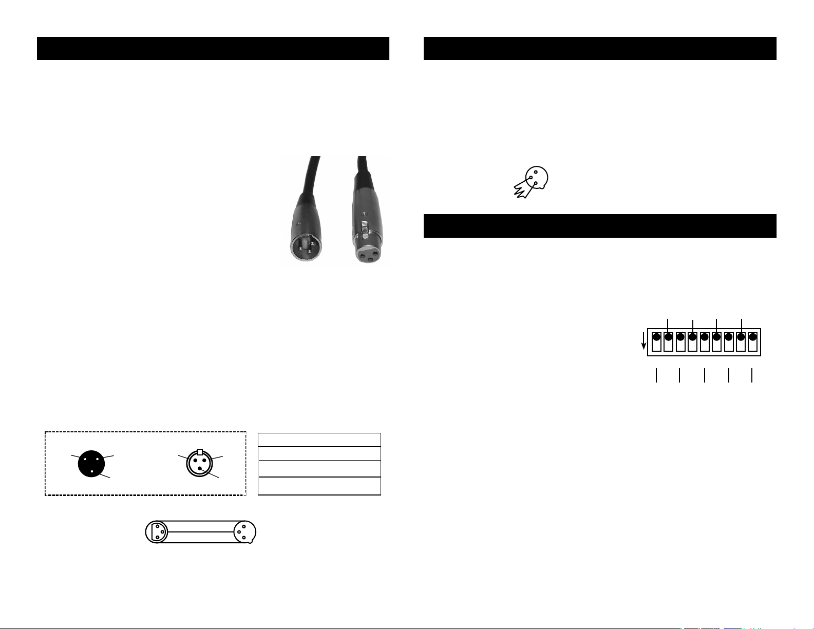
The Spiral Scan can be controlled via DMX-512
protocol. The American DJ® Spiral Scan™ is a
three channel DMX unit. The DMX address is set
on the front panel of the Spiral Scan. Your unit
and your DMX controller require a standard 3-pin
XLR connector for data input and data output
(Figure 1). If you are making your own cables, be
Figure 1
sure to use standard two conductor shielded cable (This cable may
be purchased at almost all pro sound and lighting stores). Your cables
should be made with a male and female XLR connector on either end
of the cable. Also remember that DMX cable must be daisy chained and
can not be split.
Notice: Be sure to follow gure three when making your own cables.
Do not use the ground lug on the XLR connector. Do not connect the
cable’s shield conductor to the ground lug or allow the shield conductor
to come in contact with the XLR’s outer casing. Grounding the shield
could cause a short circuit and erratic behavior.
XLR Male Socket
1 Ground
2 Cold
3 Hot
XLR Female Socket
2 Cold
1 Ground
3 Hot
XLR Pin Conguration
Pin 1 = Shield
Pin 2 = Data Compliment (negative)
Pin 3 = Data True (positive)
Special Note: Line Termination.
When longer runs of cable are
used, you may need to use a terminator on the last unit to avoid erratic
behavior. A terminator is a 90-120 ohm 1/4 watt resistor which is connected between pins 2 and 3 of a male XLR connector (DATA + and
DATA -). This unit is inserted in the female XLR connector of the last unit
in your daisy chain to terminate the line. Using a cable terminator (ADJ
part number ZDMX/T) will decrease the possibilities of erratic behavior.
Figure 4
Spiral Scan™ DMX Addressing
DMX is short for Digital Multiplex. This is a universal binary language
used as a form of communication between intelligent fixtures. Each dip
switch represents a binary value.
Dip Switch 1 address equals 1
Dip Switch 2 address equals 2
Dip Switch 3 address equals 4
Dip Switch 4 address equals 8
Dip Switch 5 address equals 16
Dip Switch 6 address equals 32
ON
DMX CHANNEL
2 8 32 128
1 2 3 54 7 986
Dip Switch 7 address equals 64
Dip Switch 8 address equals 128
Dip Switch 9 address equals 256
1 4 16 64 256
Each dip switch has a preset value, a desired DMX address is set by
combining the dip switches that will create your desired value. For
example: To achieve a DMX address of 21, combine dip switches 1, 3,
and 5. Sense dip switch 1 has a value of 1, dip switch 3 has a value
of 4, and dip switch 5 has a value of 16, the combination of the create
a DMX value of 21.
©American DJ Supply® - www.americandj.com - Spiral Scan™ Instruction Manual Page 5 ©American DJ Supply® - www.americandj.com - Spiral Scan™ Instruction Manual Page 6
Figure 2
Figure 3
Set DMX address 21: Set DMX address 201:
Dipswitches # 1 = 1 Dipswitches # 1 = 1
3 = 4 4 = 8
5 = 16 7 = 64
= 21 8 = 128
= 201
Page 4
DMXIN DMXOUT
POWER
FUSE
GMA 5AMP
ON
1 2 3 4
ON
1 2 3 4 5 6 7 8 9
OPTIONS
START ADDRESS
DMXIN DMXOUT
POWER
FUSE
GMA 5AMP
ON
1 2 3 4
ON
1 2 3 4 5 6 7 8 9
OPTIONS
START ADDRESS
DMXIN DMXOUT
POWER
FUSE
GMA 5AMP
ON
1 2 3 4
ON
1 2 3 4 5 6 7 8 9
OPTIONS
START ADDRESS
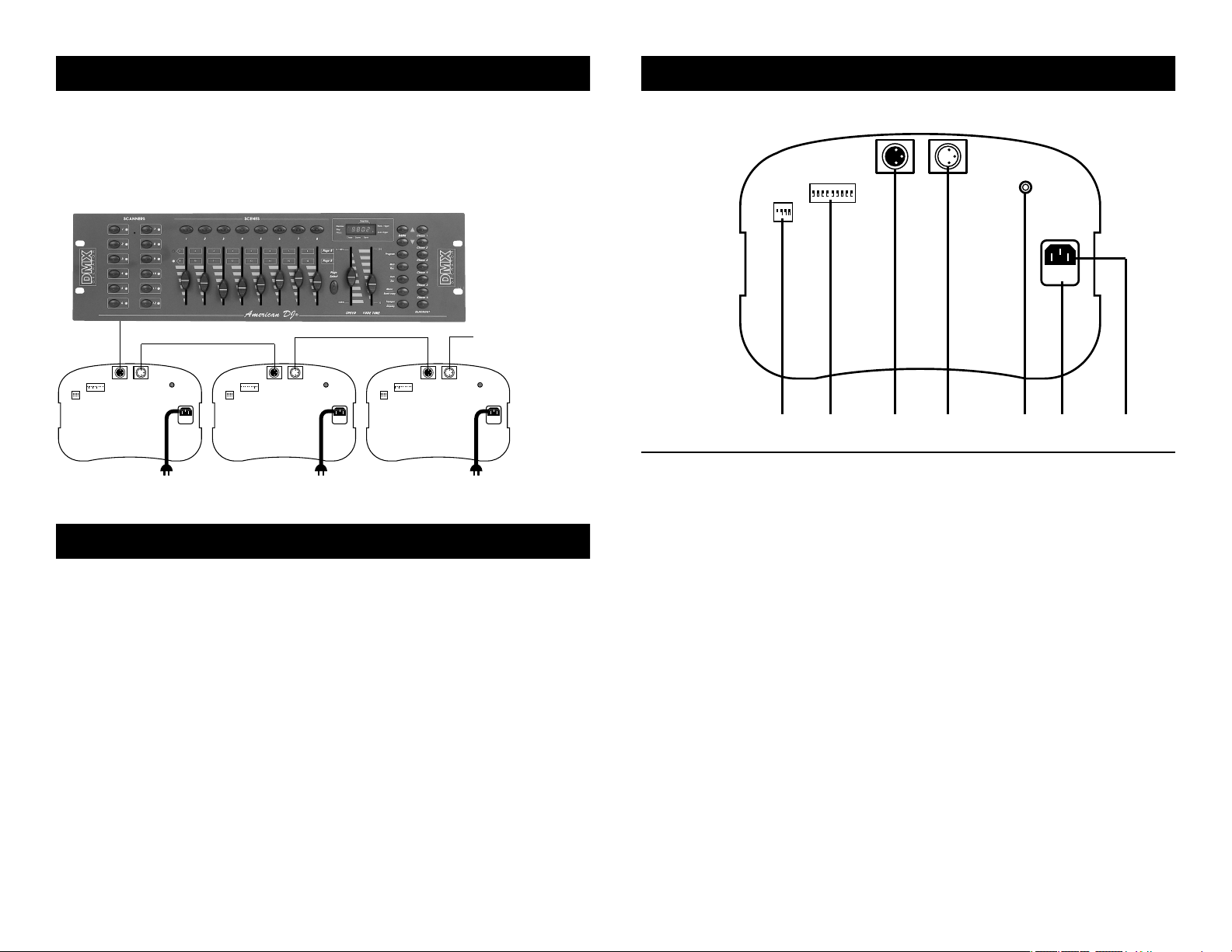
Spiral Scan™ Linking
DMX IN DMX OUT
POWER
FUSE
GMA 5AMP
ON
1 2 3 4
ON
1 2 3 4 5 6 7 8 9
OPTIONS
START ADDRESS
Linking: Your xture comes with a built-in controller. This controller
may be used to control up to 16 units when daisy-chained together in
a master-slave conguration. Any unit can function as either a “Master
Unit” or a “Slave Unit.” Link the units together using standard DMX
cable.
Spiral Scan™ Controls and Functions
Top Panel
Controller “OUT” to xture “IN”
To next xture or terminate
For a more dramatic effect, link several Spiral Scans together.
Spiral Scan™ Cleaning
Due to fog residue, smoke, and dust, cleaning the internal and external
optical lenses must be carried out periodically to optimize light output.
1. Use normal glass cleaner and a soft cloth to wipe down the outside
casing.
2. Use a brush to wipe down the fan grill.
3. Clean the external optics with glass cleaner and a soft cloth every
20 days. Situation may very. If used heavily in clubs with lots of
fog, cleaning may be required more often.
4. Clean the internal optics with glass cleaner and a soft cloth every
30-60 days.
5. Always be sure to dry all parts completely before plugging the
unit in.
Cleaning frequency depends on the environment in which the fixture
operates (i.e. smoke, fog residue, dust, dew).
©American DJ Supply® - www.americandj.com - Spiral Scan™ Instruction Manual Page 7 ©American DJ Supply® - www.americandj.com - Spiral Scan™ Instruction Manual Page 8
1 65432 7
1. Option switches - These switches will activate one of four options:
Switch 1: Focus - When activated this switch will center the
mirror with a white spot. This will allow you to focus
the beam properly.
Switch 2: Self Test - When activate this function will activate a
built in self test program.
Switch 3: Inverted Pan - When activated this switch will invert
the PAN value. Left will become right and vice versa.
Switch 4: Inverted Tilt - When activated this switch will invert the
TILT value. Up will become down and vice versa.
2. Dip Switches - These switches are used to set the DMX address.
Each switch corresponds to a specic value based on binary code.
See page 6 for a detailed explanation of DMX binary code.
3. XLR Input Jack - This jack is used to accept an incoming DMX
signal.
4. XLR Output Jack - This jack is used to send the incoming DMX
signal to another DMX xture.
5. Power Indicator - This LED will glow when main power is applied.
Page 5
6. Power Input- This male I.E.C. jack is used to feed main power to the
xture. Use the Supplied I.E.C. cord to supply main power to your
xture. Be sure the main power matches that of the required power
of your xture.
7. Fuse Holder - This houses the safety fuse. Be sure to always replace
with the exact same type, unless otherwise instructed by authorized
American DJ service technician.
Bottom Panel
Spiral Scan™ Operation Spiral Scan™ Controls and Functions
DMX Operation:
This unit must be controlled with a DMX controller. This unit is not
sound active and does not include any built in programs. For best result
we recommend the American DJ® Show Designer or the American DJ®
DMX Operator to control the Spiral Scan™.
1. Operating through a DMX controller gives the user freedom to
create custom programs tailored to personal needs. This function
also allows you to use your fixtures as spots.
2. This operation will allow you to control each individual
fixtures traits with a standard DMX 512 controller such as
the American DJ
® Show Designer
™
or the American DJ® DMX
Operator.™
3. The Spiral Scan™ uses four DMX channels to operate;
Channel 1 controls the Pan.
Channel 2 controls the Tilt.
Channel 3 controls the Color.
Channel 4 controls the Gobos.
Channel 5 controls the Gobo Rotation Speed.
4. To run your fixture in DMX mode, plug in the fixture via the
XLR connections to any standard DMX controller. Follow the
set-up specifications that come with the controller.
5. Use your controller to control the various fixture traits (Pan, Tilt,
Color, Gobo, and Gobo Rotation Speed). A complete break down
of the DMX traits can be found on page 14 of this manual.
Auto-Mate™/DMX Solo™ Operation:
The Auto-Mate™ and DMX Solo™ by American DJ
®, are mini DMX
controllers that come with built-in programs exclusively for the Spiral
8 109
Scan.™ The Auto-Mate includes eight programs and the DMX Solo™
includes 16 built-in programs. Please note that all programs in the Auto-
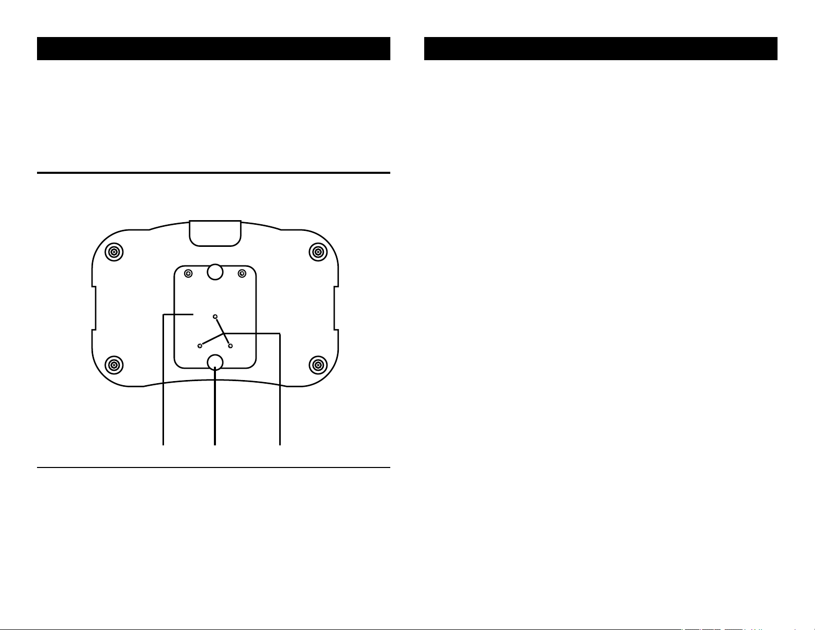
8. Lamp Socket Assembly Plate - This plate accesses the lamp socket
assembly.
9. Thumb Screw - These two thumb screw hold the assembly plate into
place.
10. Lamp Optimization Screws - These three screws are spring loaded
and are used to optimize the lamp. Use these three screws to
center the lamp in the reector.
©American DJ Supply® - www.americandj.com - Spiral Scan™ Instruction Manual Page 9 ©American DJ Supply® - www.americandj.com - Spiral Scan™ Instruction Manual Page 10
Mate™ are preset, but may be changed with the American DJ™ Show
Designer.™ You may wish to use this optional controller as an inexpensive alternative to a full featured DMX controller. This option will also
allow the xture to be sound active. All set-up and installations procedures are the same as a standard DMX operation. For more information
on either of these two optional controllers, please contact our toll free
customer support number or see us on the web.
Page 6
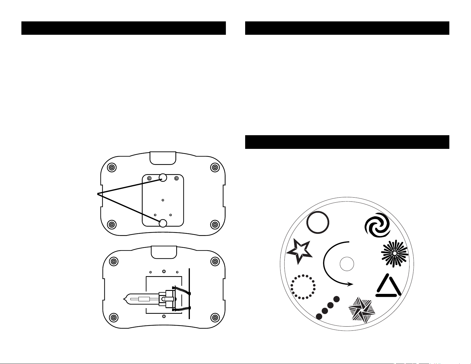
Spiral Scan™ Lamp Replacement
1
Spiral Scan™ Focusing
Lamp Replacement: Caution! Never open the unit when in use.
Always disconnect the main power and allow the unit ample time to
cool before attempting to replace the lamp. Remember always replace
with the same type lamp and fuse.
1. Be sure to follow the proper procedures when handling discharge
lamps.
2. Lamp replacement has been made simple by incorporating the
use of a removable cover and thumb screws.
3. Remove the two thumb screws on bottom of the unit that hold the
socket assembly in place.
4. Carefully pull out the socket assembly.
5. Remove and replace the bulb.
6. Reassemble.
Retaining thumb screws
Focusing:
1. To focus a Spiral Scan,™ disconnect main power and flip the option
dip switch one to the on position. Then reconnect main power.
2. After the unit resets the lamp will strike. The mirror will center and
a preselected gobo will projected.
3. Loosen the thumb screw on the front of the unit that hold the lens
in place.
4. Adjust the focus by manually moving the lens up and down.
5. Tighten the thumb screw after you achieve your desired focus.
6. Disconnect main power and return the number one option dip
switch to the off position.
7. Reconnect main power.
Spiral Scan™ Gobos
This chart details the gobo pattern as well as the gobo wheel placement. When used with a DMX controller gobo one may be used as
a spot or color changer. Gobos two through eight will rotate, rotation
will be controlled by DMX channel ve. Gobos two through eight may
also be replaced with custom gobos. Please contact customer service
for custom gobos.
Lamp Socket Assembly
©American DJ Supply® - www.americandj.com - Spiral Scan™ Instruction Manual Page 11
©American DJ Supply® - www.americandj.com - Spiral Scan™ Instruction Manual Page 12
Page 7
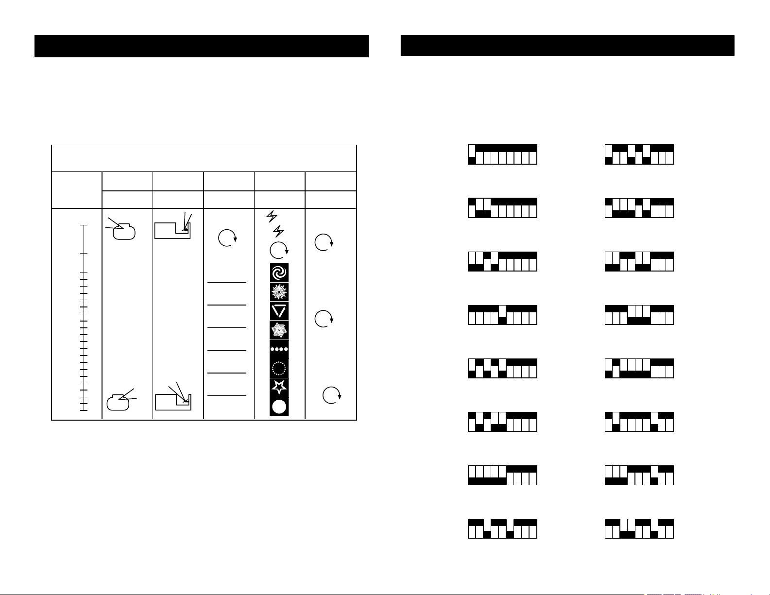
The Spiral Scan™ is a ve DMX channel intelligent scanner. This chart
CHANNEL
1 2 3 4
COLOR GOBO
DMX512
LEVEL RANGE
0 - 255
~
PAN TILT
MAGENTA
ORANGE
YELLOW
GREEN
BLUE
RED
BLACKOUT
5
ROTATION
99
95
89
85
79
75
69
65
59
55
49
45
39
35
29
25
19
15
9
5
0
255
200
X 3
X 7
X 7
details the DMX traits of the Spiral Scan.™ Use your controller’s fader
levels to scroll through the different values. Each fader value dictates
the xtures operation.
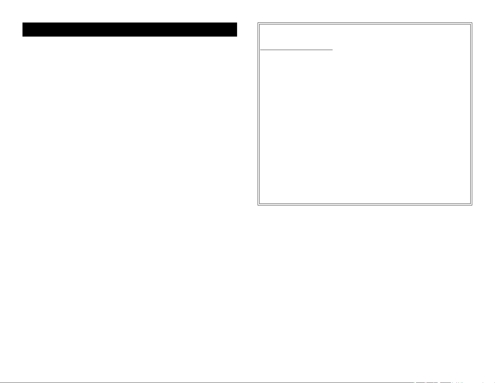
Spiral Scan™ DMX Dip Switch Chart Spiral Scan™ Traits
This chart list the DMX dip switch setting for the first 16 units. This
chart is set as a guide only. Please follow standard binary DMX
protocol as described on page 6 for proper dip switch settings beyond
the sixteenth unit or for units not starting at DMX channel one. For
the American DJ® DMX Operator™ setting please refer to the DMX
Operator™ manual.
Head 1 - Address 1
Head 9 - Address 41
ON
1 98765432
Head 2 - Address 6
ON
1 98765432
Head 3 - Address 11
ON
1 98765432
Head 4 - Address 16
ON
1 98765432
Head 5 - Address 21
ON
1 98765432
Head 6 - Address 26
ON
1 98765432
Head 7 - Address 31
ON
1 98765432
ON
1 98765432
Head 10 - Address 46
ON
1 98765432
Head 11 - Address 51
ON
1 98765432
Head 12 - Address 56
ON
1 98765432
Head 13 - Address 61
ON
1 98765432
Head 14 - Address 66
ON
1 98765432
Head 15 - Address 71
ON
1 98765432
Head 8 - Address 36 Head 16 - Address 76
ON
1 98765432
©American DJ Supply® - www.americandj.com - Spiral Scan™ Instruction Manual Page 14©American DJ Supply® - www.americandj.com - Spiral Scan™ Instruction Manual Page 13
ON
1 98765432
Page 8
Spiral Scan™ Warranty
1-YEAR LIMITED WARRANTY
A. American DJ® hereby warrants, to the original purchaser, American DJ® products to be
free of manufacturing defects in material and workmanship for a period of 1 Year (365 days)
from the date of purchase. This warranty shall be valid only if the product is purchased within
the United States of America, including possessions and territories. It is the owner’s responsibility to establish the date and place of purchase by acceptable evidence, at the time service is sought.
B. For warranty service, send the product only to the American DJ® factory. All shipping
charges must be pre-paid. If the requested repairs or service (including parts replacement)
are within the terms of this warranty, American DJ® will pay return shipping charges only to a
designated point within the United States. If the entire instrument is sent, it must be shipped
in its original package. No accessories should be shipped with the product. If any accessories
are shipped with the product, American DJ® shall have no liability whatsoever for loss of or
damage to any such accessories, nor for the safe return thereof.
C. This warranty is void if the serial number has been altered or removed; if the product
is modied in any manner which American DJ® concludes, after inspection, affects the reliability of the product; if the product has been repaired or serviced by anyone other than the
American DJ® factory unless prior written authorization was issued to purchaser by American DJ®; if the product is damaged because not properly maintained as set forth in the
instruction manual.
D. This is not a service contract, and this warranty does not include maintenance, cleaning
or periodic check-up. During the period specied above, American DJ® will replace defective
parts at its expense, and will absorb all expenses for warranty service and repair labor by
reason of defects in material or workmanship. The sole responsibility of American DJ® under
this warranty shall be limited to the repair of the product, or replacement thereof, including
parts, at the sole discretion of American DJ®. All products covered by this warranty were
manufactured after January 1, 1990, and bear identifying marks to that effect.
E. American DJ® reserves the right to make changes in design and/or improvements upon
its products without any obligation to include these changes in any products theretofore
manufactured.
MODEL: SPIRAL SCAN™
SPECIFICATIONS:
VOLTAGE*: 120v~60Hz / 220v~50Hz
LAMP: SC-150 120v/150w
DIMENSIONS: 23” H X 10.5” W X 11” D (with
yoke extended)
WEIGHT: 31 LBS / 12.5 KGS.
FUSE: 5 AMP GMA
WORKING POSITION: ANY SAFE POSITION
COOLING: FAN COOLED
DUTY CYCLE: 30 MIN. ON, 10 MIN. OFF
GOBOS: 7 PLUS SPOT - CHANGEABLE
(26mm outer diameter -
22mm viewing image)
COLORS: 7 PLUS WHITE - SPLIT
COLOR CAPABLE
DMX CHANNELS: 5
Sound Active: No
* Operating voltage is preset at the factory.
Please Note: Specications and improvements in the design of
this unit and this manual are subject to change without any prior
written notice.
F. No warranty, whether expressed or implied, is given or made with respect to any accessory supplied with products described above. Except to the extent prohibited by applicable
law, all implied warranties made by American DJ® in connection with this product, including
warranties of merchantability or tness, are limited in duration to the warranty period set forth
above. And no warranties, whether expressed or implied, including warranties of merchantability or tness, shall apply to this product after said period has expired. The consumer’s and
or Dealer’s sole remedy shall be such repair or replacement as is expressly provided above;
and under no circumstances shall American DJ® be liable for any loss or damage, direct or
consequential, arising out of the use of, or inability to use, this product.
G. This warranty is the only written warranty applicable to American DJ® Products and
supersedes all prior warranties and written descriptions of warranty terms and conditions
heretofore published.
H. Lamps are not covered under this or any other warranty, either written or implied.
©American DJ Supply® - www.americandj.com - Spiral Scan™ Instruction Manual Page 15
©American DJ World Headquarters:
4295 Charter Street Los Angeles, CA 90058 USA
Tel: 323-582-2650 Fax: 323-582-2610
Web: www.americandj.com E-mail: [email protected]
 Loading...