

Page 1
SP-1500 DM X MK II Strobe
10/2011
Operation Manual
A.D.J. Supply Europe B.V.
6468 EW Kerkrade
www.americandj.eu
A.D.J. Supply Europe B.V. – www.americandj.eu – SP-1500 DMX MKII Strobe Manual Page 1
Junostraat 2
The Netherlands
Page 2

Table of contents
INTRODUCTION .......................................................................................................................................................................3
FEATURES ................................................................................................................................................................................4
INSTALLATION .........................................................................................................................................................................4
DMX ADRESSING .....................................................................................................................................................................5
MASTER/SLAVE MODE ............................................................................................................................................................6
LAMP REPLACEMENT ..............................................................................................................................................................7
FIXTURE CLEANING .................................................................................................................................................................7
FUSE REPLACEMENT ...............................................................................................................................................................8
TROUBLE SHOOTING ...............................................................................................................................................................8
TECHNICAL SPECIFICATIONS ...................................................................................................................................................8
A.D.J. Supply Europe B.V. – www.americandj.eu – SP-1500 DMX MKII Strobe Manual Page 2
Page 3
INTRODUCTION
Aggressor Tri LED™ Introduction
Thank you for purchasing the American DJ SP-1500 DMX MKII Strobe. To optimize the performance of this
product, please read these operating instructions carefully to f amiliarize yourself with the basic operations
of this unit.
Customer Support:
American DJ® provides a toll free customer support line, to provide set up help and to answer any question
should you encounter problems during your set up or initial operation. You may also visit us on the web at
www.americandj.eu for any comments or suggestions.
E-mail: service@americandj.eu
To purchase parts onlin e visit www.adjparts.eu
Warning!
To prevent or reduce the risk of electrical shock or fire, do not expose this unit to rain or
moisture.
Caution! There are no user serviceable parts inside this unit. Do not attempt any repairs yourself, doing so
will void your manufactures warranty. In the unlikely event your unit may require service please contact
your American DJ reseller.
• Do not obstruct the air vents.
• Do not touch the unit while it’s hot.
Do not discard the shipping carton in the trash. Please recycle whenever possible.
Aggressor Tri LED™ Features
FEATURES
• Includes hanging bracket
• Sound-Active
• DMX-512, Master/Slave
• Electronic Dimmer 0-100%
• Built-in microphone
• Compatible with UC3-Series controllers
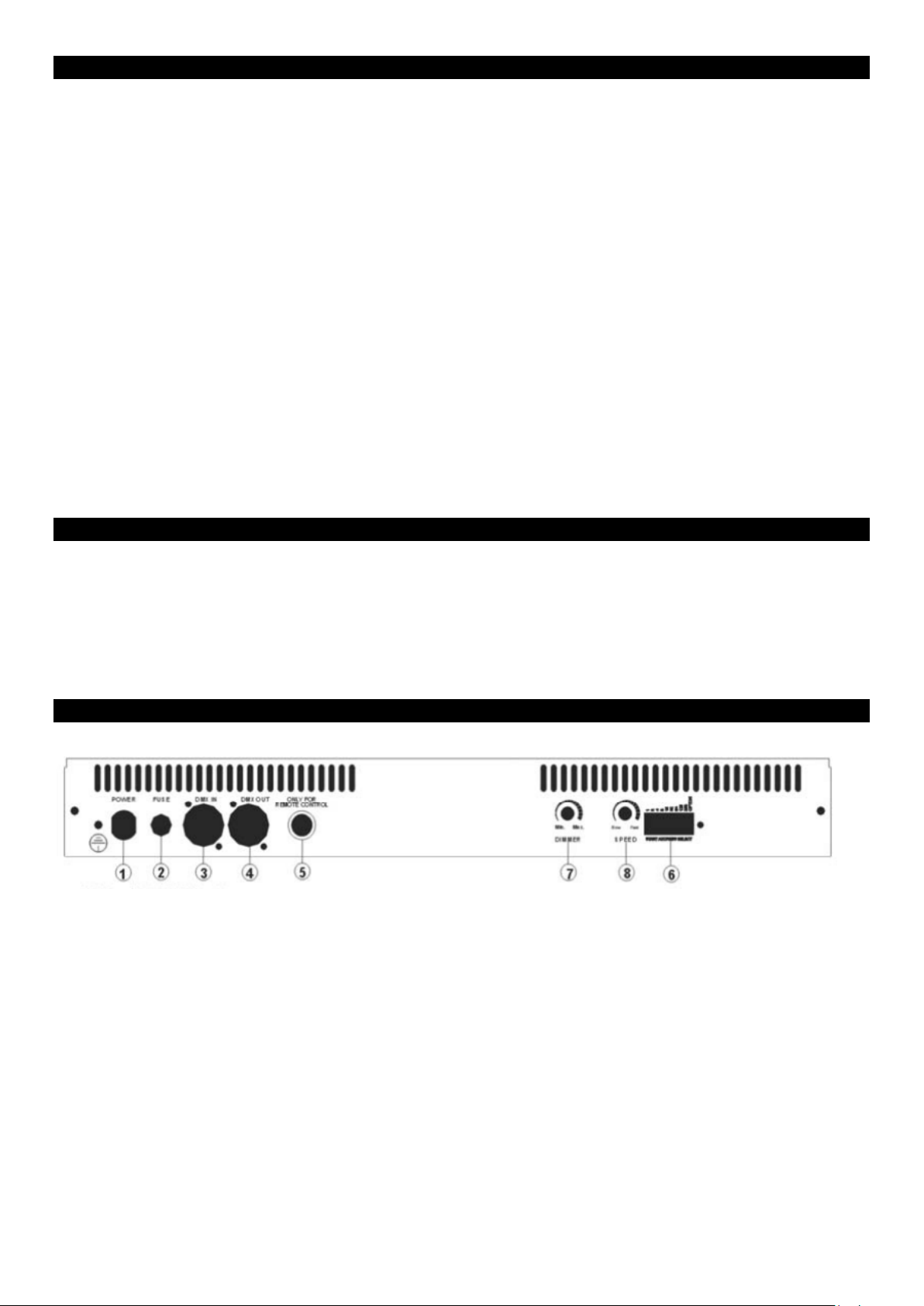
INSTALLATION
1. POWER INPUT: AC 230V 50Hz
2. FUSE: 20A/15A
3. DMX IN: XLR 3 Pole male socket.
4. DMX OUT: XLR 3 Pole female socket.
5. UC3 Remote input: connect the UC3 to the ¼” microphone Jack to control
the unit for Speed, Blackout and Brightness.
6. DMX DIP SWITCH: Dip switch 1-9 are used to set the DMX address of the unit.
7. DIMMER: This knob is used to adjust the brightness of the units.
8. SPEED: This knob is used to adjust the strobing speed.
The unit should be mounted via its screw holes on the bracket. Always ensure that the unit is firmly fixed to
avoid vibration and slipping while operating. Use a safety chain to secure the strobe. The equipment must
be fixed by professionals. And it must be fixed at a place where is out of reach of people.
A.D.J. Supply Europe B.V. – www.americandj.eu – SP-1500 DMX MKII Strobe Manual Page 3
Page 4

Power Supp l y: Before plugging your unit in, be sure the source voltage in your area matches the required
voltage for your American DJ
Strobe is only available in a 230v version. Because line voltage may vary from venue to venue, you should
be sure your unit voltage matches the wall outlet voltage before attempting to operate you fixture. Also be
sure to only use the included I.E.C. power cable supplied with the unit, this cable matches the voltage and
current requirements of the unit.
® SP-1500 DMX MK II STROBE. The American DJ® SP-1500 DMX MK II
DMX-512: DMX is short for Digital Multiplex. This is a universal protocol used by most lighting and
controller manufactures as a form of communication between intelligent fixtures and controllers. A DMX
controller sends DMX data instr uctions from the controller to the fixture. DMX data is sent as serial data
that travels from fixture to fixture via the DATA “IN” and DATA “OUT” XLR terminals located on all DMX
fixtures (most controllers only have a DATA “OUT” terminal).
DMX Linking: DMX is a language allowing all makes and models of different manufactures to be linked
together and operate from a single controller, as long as all fixtures and the controller are DMX compliant.
To ensure proper DMX data transmission, when using several DMX fixtures try to use the shortest cable
path possible. The order in which fixtures are connected in a DMX line does not influence the DMX
addressing. For example; a fixture assigned a DMX address of 1 may be placed anywhere in a DMX line, at
the beginning, at the end, or anywhere in the middle. Therefore, the first fixture controlled by the controller
could be the last fixture in the chain. When a fixture is assigned a DMX address of 1, the DMX controller
knows to send DATA assigned to address 1 to that unit, no matter where it is located in the DMX chain.
Data Cable (DMX Cable) Requirements (For DMX and Master/Slave Operation):
The SP-1500 DMX MK II can be controlled via DMX-512 protocol. The SP-1500
DMX MK II is controlled by 2 DMX channels : 1 channel for strobe speed and 1
channel for intensity. The DMX address is set electronically using the dipswitches
on the back of the unit. Your unit and your DMX controller require a standard 3-pin
XLR connector for data input and data output (Figure 1). If you are making your
own cables, be sure
may be purchased at almost all professional sound and lighting stores). Your
cables should be made with a male and female XLR connector on either end of
the cable. Also remember that DMX cable must be daisy chained and cannot be
split.
to use standard two conductors shielded cable (This cable
Figure 1
Notice: Be sure to follow figures two and three when making your own cables. Do not use the ground lug
on the XLR connector. Do not connect the cable’s shield conductor to the ground lug or allow the shield
conductor to come in contact with the XLR’s outer casing. Grounding the shield could cause a short circuit
and erratic behavior.
Figure 2
Figure 3
A.D.J. Supply Europe B.V. – www.americandj.eu – SP-1500 DMX MKII Strobe Manual Page 4
Page 5

Special Note: Line Termi nation. When longer runs of cable are used, you may need to use a terminator
3-Pin XLR to 5-Pin XLR Conversion
#1 #2 #3 #4 #5 #6 #7 #8 #9
2 4 8
on the last unit to avoid erratic behavior. A terminator is a 90-120 ohm 1/4 watt resistor which is connected
between pins 2 and 3 of a male XLR connector (DATA + and DATA -). This unit is inserted in the female
XLR connector of the last unit in your daisy chain to terminate the line. Using a cable terminator (ADJ part
number 1613000030) will decrease the possibilities of erratic behavior.
Termination reduces signal errors and avoids signal transmission problems and
interference. It is always advisable to connect a DMX terminal, (Resistance of
120 Ohm 1/4 W) between PIN 2 (DMX-)and PIN 3 (DMX +) of the last fixture.
5-Pin XLR DMX Connectors.
Some manufactures use 5-pin XLR connectors for DATA transmission in
place of 3-pin. 5-pin XLR fixtures may be implemented in a 3-pin XLR DMX line. When inserting standard
5-pin XLR connectors in to a 3-pin line a cable adaptor must be used, these adaptors are readily available
at most electric stores. The chart below details a proper cable conversion.
Conductor
Ground/Shield
Data Compliment
Data True (+
DMX ADRESSING
Not Used
Not Used
(- signal)
signal)
3-Pin
XLR Female
Pin 1
Pin 2
Pin 3
(Out)
5-Pin
XLR
Pin
4 - Do Not Use
Pin
5 - Do Not Use
Male (In)
Pin 1
Pin 2
Pin 3
DMX IN 120 Ohm 1/4W
If you use a universal DMX controller to control the units, you have to set dip switches from 1
to 9 of the channel so that all the units will receive its DMX signal. Please refer to the
following diagram to know how to address your DMX512 system in the binary code.
Dip
Value 1
16 32 64 128 256 Option
#10
A.D.J. Supply Europe B.V. – www.americandj.eu – SP-1500 DMX MKII Strobe Manual Page 5
Page 6

DMX512 Traits
DMXValue
240~255
224~239
208~223
192~207
176~191
160~175
144~159
128~143
112~127
96~111
80~95
64~79
48~63
32~47
16~31
0~15
Channel 1
Strobe Speed
Speed 15
Speed 14
Speed 13
Speed 12
Speed 11
Speed 10
Speed 9
Speed 8
Speed 7
Speed 6
Speed 5
Speed 4
Speed 3
Speed 2
Speed 1
STOP
Channel 2
Dimmer
Dimmer 15
Dimmer 14
Dimmer 13
Dimmer 12
Dimmer 11
Dimmer 10
Dimmer 9
Dimmer 8
Dimmer 7
Dimmer 6
Dimmer 5
Dimmer 4
Dimmer 3
Dimmer 2
Dimmer 1
BLACKOUT
MASTER/SLAVE MODE
By linking the units in master/slave connection, the first unit will control the other
units to give an automatic light show. You will know which unit is the master
because its DMX input jack will have nothing plugged into it. The other units
(slaves) will have DMX cables plugged into the DMX input jacks (daisy chain).
You can set the units in below two ways:
1. Synchronized show: set the first (Master) unit’s dipswitches 1 and 10 to ON,
now you can adjust the dimmer and strobe speed, and all the other (slave) units will
follow the Master unit.
2. 4-units Lightshow: set the dipswitch as the diagram,
the first (master) unit will run the built-in
programmer and control the other (slave) units separately like a 4 channel chaser.
Chase pattern in the 4-units lightshow mode:
Pattern 1
Pattern 2
Pattern 3
Pattern 4
Pattern 5
Pattern 6
Units 1,2,3,4 all Full on
Chase unit 1->2->3->4 ― 4->3->2->1
Chase unit 1->2->3->4-4->3->2->1
Chase Units1&2->3&4 ― 2&3->1&4
Chase 1-1&2-1&2&3-ALL-1&2&3-1&2-1-stop ― 4-4&3-4&3&2-ALL-4&3&2-4&3-4-stop
Chase 1->2->1->2->3->4->3->4―4->1->4->1->3->2->3->2
A.D.J. Supply Europe B.V. – www.americandj.eu – SP-1500 DMX MKII Strobe Manual Page 6
Page 7

LAMP REPLACEMENT
2. Open the glass base-cover.
3. Loose the screws of the lamp wire from terminator.
4. Take out the old lamp and place the new one into the
fixture.
5. Connect the lamp wire to the terminator.
6. Reverse the procedures from step 2 to step 1.
FIXTURE CLEANING
Due to fog residue, smoke, and dust cleaning the internal and external optical lenses must be carried out
periodically to optimize light output.
1. Use normal glass cleaner and a soft cloth to wipe down the outside casing.
2. Use a brush to wipe down the fan grill.
3. Clean the external optics with glass cleaner and a soft cloth every 20 days.
5. Always be sure to dry all parts completely before plugging the unit back in.
Cleaning frequency depends on the environment in which the fixture operates (I.e. smoke, fog residue,
dust). In heavy club use we recommend cleaning on a monthly basis. Periodic cleaning will ensure
longevity and crisp output.
A.D.J. Supply Europe B.V. – www.americandj.eu – SP-1500 DMX MKII Strobe Manual Page 7
Page 8

FUSE REPLACEMENT
First unplug the power. The fuse holder is located at the rear of the unit next to the power cord. Using a flathead screw driver unscrew the fuse holder. Remove the bad fuse and replace with a new one.
TROUBLE SHOOTING
Listed below are a few common problems that you may encounter, with solutions.
No light output from t he unit:
1) Be sure you have connected your unit into a standard 230v wall outlet.
2) Be sure the fuse has not blown. The fuse is located on the rear panel.
Unit does not respond to sound:
1) Low frequencies (bass) should cause the unit to react to sound. Tapping on the microphone, quiet or
high pitched sounds may not activate the unit.
TECHNICAL SPECIFICATIONS
Lamp XENON 1500W
Power AC 230V 50Hz
Fuse Circuit breaker 20A
Dimensions
Weight 3.2 kg
452 x 147.5 x 116 mm
A.D.J. Supply Europe B.V.
Junostraat 2
6468 EW Kerkrade
The Netherlands
www.americandj.eu
A.D.J. Supply Europe B.V. – www.americandj.eu – SP-1500 DMX MKII Strobe Manual Page 8
 Loading...