

Page 1
HYDRO BEAM X1
User Instructions
Page 2

©2019 ADJ Products, LLC all rights reserved. Information, specications, diagrams, images, and
with the included instructions, may cause harmful interference to radio communications. However, there is
instructions herein are subject to change without notice. ADJ Products, LLC logo and identifying
product names and numbers herein are trademarks of ADJ Products, LLC. Copyright protection
claimed includes all forms and matters of copyrightable materials and information now allowed by
statutory or judicial law or hereinafter granted. Product names used in this document may be
trademarks or registered trademarks of their respective companies and are hereby acknowledged.
All non-ADJ Products, LLC brands and product names are trademarks or registered trademarks of
their respective companies.
ADJ Products, LLC and all aliated companies hereby disclaim any and all liabilities for property,
equipment, building, and electrical damages, injuries to any persons, and direct or indirect economic
loss associated with the use or reliance of any information contained within this document, and/or as
a result of the improper, unsafe, unsucient and negligent assembly, installation, rigging, and operation
of this product.
FCC STATEMENT
This device complies with Part 15 of the FCC Rules. Operation is subject to the following two conditions:
(1) this device may not cause harmful interference, and (2) this device must accept any interference
received, including interference that may cause undesired operation.
FCC RADIO FREQUENCY INTERFERENCE WARNINGS & INSTRUCTIONS
This product has been tested and found to comply with the limits as per Part 15 of the FCC Rules. These
limits are designed to provide reasonable protection against harmful interference in a residential installation. This device uses and can radiate radio frequency energy and, if not installed and used in accordance
no guarantee that interference will not occur in a particular installation. If this device does cause harmful
interference to radio or television reception, which can be determined by turning the device off and on, the
user is encouraged to try to correct the interference by one or more of the following methods:
· Reorient or relocate the device.
· Increase the separation between the device and the receiver.
· Connect the device to an electrical outlet on a circuit different from which the radio receiver is
connected.
· Consult the dealer or an experienced radio/TV technician for help.
DOCUMENT VERSION
Due to additional product features and/or enhancements, an updated version of this document
may be available online.
Please check www.adj.com for the latest revision/update of this manual before beginning
installation and/or programming.
Date
08/21/19
Document
Version
1 1.0
Software
Version >
DMX Channel
Mode
11 / 14 Initial Version
Notes
Europe Energy Saving Notice
Energy Saving Matters (EuP 2009/125/EC)
Saving electric energy is a key to help protecting the enviroment. Please turn o all electrical products when
they are not in use. To avoid power consumption in idle mode, disconnect all electrical equipment from power
when not in use. Thank you!
Page 3

Hydro Beam X1 Table of Contents
Introduction
Features I Warranty Registration
IP65 Notice
Safety Guidelines
Overview
Discharge Lamp Warning
Lamp Installation
Torque Settings & IP Tester
Screw Locations
Fixture Installation
Connections
3
4
5
6
10
11
13
15
16
17
20
DMX Set Up
DMX Addressing
DMX Channel Modes
Gobos
System Menu
WiFly Control
Error Codes
Dimensional Drawings
Power Linking I Cleaning
Limited Warranty (USA Only)
Technical Specications
21
23
24
25
26
33
35
36
37
38
39
ADJ Products, LLC - www.adj.com - Hydro Beam X1 User Manual Page 2
Page 4

Hydro Beam X1 Introduction
Unpacking: Thank you for purchasing the Hydro Beam X1 by ADJ Products, LLC. Every Hydro Beam
X1 has been thoroughly tested and has been shipped in perfect operating condition. Carefully check
the shipping carton for damage that may have occurred during shipping. If the carton appears to be damaged, carefully inspect your xture for any damage and be sure all accessories necessary to operate
the unit has arrived intact. In the case damage has been found or parts are missing, please contact our
toll free customer support number for further instructions. Do not return this unit to your dealer without
rst contacting customer support.
Introduction: The ADJ Hydro Beam X1 is a DMX intelligent, IP rated, high powered, moving head fixture.
To optimize the performance of this product, please read these operating instructions carefully to
familiarize yourself with the basic operations of this unit. This product is intended to be used by
professionally trained personnel only and is not suitable for private use.
These instructions contain important safety information regarding the use and maintenance of this
unit. Please keep this manual with the unit, for future reference.
Customer Support: Contact ADJ Service for any product related service and support needs. Also visit
forums.adj.com with questions, comments or suggestions.
Parts: To purchase parts online visit:
http://parts.adj.com (US)
http://www.adjparts.eu (EU)
ADJ SERVICE USA - Monday - Friday 8:00am to 4:30pm PST
Voice: 800-322-6337 | Fax: 323-832-2941 | support@adj.com
ADJ SERVICE EUROPE - Monday - Friday 08:30 to 17:00 CET
Voice: +31 45 546 85 60 | Fax: +31 45 546 85 96 | support@adj.eu
ADJ PRODUCTS LLC USA
6122 S. Eastern Ave. Los Angeles, CA. 90040
323-582-2650 | Fax 323-532-2941 | www.adj.com | info@adj.com
ADJ SUPPLY Europe B.V
Junostraat 2 6468 EW Kerkrade, The Netherlands
+31 (0)45 546 85 00 | Fax +31 45 546 85 99
www.adj.eu | info@adj.eu
ADJ PRODUCTS GROUP Mexico
AV Santa Ana 30 Parque Industrial Lerma, Lerma, Mexico 52000
+52 (728) 282-7070
Caution! There are no user serviceable parts inside this unit. Do not attempt any repairs yourself,
doing so will void your manufactures warranty. In the unlikely event your unit may require service
please contact ADJ Products, LLC.
PLEASE recycle the shipping carton when ever possible.
ADJ Products, LLC - www.adj.com - Hydro Beam X1 User Manual Page 3
Page 5

Hydro Beam X1 Features
• IP65 Outdoor Rated
• Electronic Dimming 0-100%
• DMX-512 protocol
• 5-Pin DMX Connection
• Multiple DMX Modes
• IP65 Twist Lock Power In & Out
• Colors: 14 + Open (Including CTB & UV)
• Gobos: 15 Gobos + Open
• Prism: Rotating 16-Facet Circular
• Frost Effect
• Multiple Unit Power Linking (See page 37)
Included:
1 x IP65 Twist Lock Power Cable
2 x Omega Brackets
Hydro Beam X1 Warranty Registration
The Hydro Beam X1 carries a 2 year limited warranty. Please fill out the enclosed warranty card to
validate your purchase. All returned service items whether under warranty or not, must be freight prepaid and accompany a return authorization (R.A.) number. The R.A. number must be clearly written on
the outside of the return package. A brief description of the problem as well as the R.A. number must
also be written down on a piece of paper included in the shipping carton. If the unit is under warranty, you must provide a copy of your proof of purchase invoice. You may obtain a R.A. number by
contacting our customer support team on our customer support number. All packages returned to the
service department not displaying a R.A. number on the outside of the package will be returned to the
shipper.
ADJ Products, LLC - www.adj.com - Hydro Beam X1 User Manual Page 4
Page 6

Hydro Beam X1 IP Notice
IP65 RATED
An IP rated lighting xture is one, which is commonly installed in outdoor environments
and has been designed with an enclosure that eectively protects the ingress (entry)
of external foreign objects such as dust and water. The International Protection (IP)
rating system is commonly expressed as "IP" (Ingress Protection) followed by two
numbers (i.e. IP65) where the numbers dene the degree of protection. The rst digit
(Foreign Bodies Protection) indicates the extent of protection against particles entering
the xture and the second digit (Water Protection) indicates the extent of protection
against water entering the xture. An IP65 rated lighting xture is one, which has been
designed and tested to protect against the ingress of dust (6) and high-pressure water
jets from any direction (5).
MARINE/COASTAL ENVIRONMENT INSTALLATIONS
NOT suitable for marine and/or coastal environment installations. Installing
this xture in a marine and/or coastal environment may cause corrosion and/
or excessive wear to the interior and/or exterior components of the xture.
Damages and/or performance issues resulting from installation in a marine
and/or coastal environment will void the manufactures warranty and will NOT be subject
to any warranty claims and/or repairs.
ADJ Products, LLC - www.adj.com - Hydro Beam X1 User Manual Page 5
Page 7

Hydro Beam X1 Safety Guidelines
FOR YOUR OWN PERSONAL SAFETY, PLEASE READ AND UNDERSTAND THIS MANUAL COMPLETELY
BEFORE YOU ATTEMPT TO INSTALL OR OPERATE THIS UNIT!
• THERE ARE NO USER SERVICEABLE PARTS INSIDE THIS UNIT. DO NOT ATTEMPT ANY REPAIRS
YOURSELF; DOING SO WILL VOID YOUR MANUFACTURES WARRANTY. DAMAGES RESULTING FROM
MODIFICATIONS TO THIS FIXTURE AND/OR THE DISREGARD OF SAFETY INSTRUCTIONS AND
GUIDELINES IN THIS MANUAL VOID THE MANUFACTURES WARRANTY AND ARE NOT SUBJECT TO
ANY WARRANTY CLAIMS AND/OR REPAIRS.
• DO NOT PLUG THE FIXTURE INTO A DIMMER PACK!
NEVER OPEN THIS FIXTURE WHILE IN USE!
UNPLUG POWER BEFORE SERVICING FIXTURE!
NEVER TOUCH THE FIXTURE DURING OPERATION AS IT MAY BE HOT!
KEEP FLAMMABLE MATERIALS AWAY FROM FIXTURE!
• ENSURE ALL CONNECTIONS AND END CAPS ARE PROPERLY SEALED WITH A DIELECTRIC GREASE
(AVAILABLE AT MOST ELECTRICAL SUPPLIERS) TO PREVENT WATER CORROSION AND/OR
ELECTRICAL SHORT CIRCUIT.
• IF THE FIXTURE IS EXPOSED TO ENVIRONMENTAL TEMPERATURE CHANGES SUCH AS RELOCATION
FROM AN OUTDOOR COLD TO AN INDOOR WARM ENVIRONMENT, DO NOT POWER THE FIXTURE
ON IMMEDIATELY. INTERNAL CONDENSATION AS A RESULT OF ENVIROMENTAL TEMPERATURE
CHANGE CAN CAUSE INTERNAL FIXTURE DAMAGE. LEAVE THE FIXTURE POWERED OFF UNTIL IT HAS
REACHED ROOM TEMPERATURE BEFORE POWERING ON.
• NEVER LOOK DIRECTLY INTO THE LIGHT SOURCE! RETINA INJURY RISK - MAY INDUCE BLINDNESS!
SENSITIVE PERSONS MAY SUFFER AN EPILEPTIC SHOCK!
• Be sure that the local power outlet is compatible with the required voltage for your unit.
• Do not attempt to operate this unit if the power cord has been frayed or broken.
• Do not attempt to remove or break o the ground prong from the electrical cord. This prong is used to
reduce the risk of electrical shock and re in case of an internal short.
• Disconnect from main power before making any type of connection.
• Do not remove the cover under any conditions. There are no user serviceable parts inside.
• Never operate this unit when it’s cover is removed.
• Always be sure to mount this unit in an area that will allow proper ventilation. Allow about 6” (15cm) between this
device and a wall.
• Do not attempt to operate this unit, if it becomes damaged.
• Always mount this unit in safe and stable matter.
• Power-supply cords should be routed so that they are not likely to be walked on or pinched by items placed
upon or against them, paying particular attention to cords at plugs, convenience receptacles, and the point
where they exit from the appliance.
• Cleaning -The fixture should be cleaned only as recommended by the manufacturer. See page 35 for cleaning
details.
• Heat -This fixture should be situated away from heat sources such as radiators, heat registers, stoves, or other
appliances (including amplifiers) that produce heat.
• The fixture should be serviced by qualified service personnel when the appliance does not appear to operate
normally or exhibits a marked change in performance.
ADJ Products, LLC - www.adj.com - Hydro Beam X1 User Manual Page 6
Page 8

Hydro Beam X1 Safety Guidelines
SENSITIVE PERSONS MAY SUFFER AN EPILEPTIC SHOCK!
SAFETY G U I DELI NES
To guarantee a smooth operation, it is important to follow all instructions and guidelines in
this manual. ADJ Products, LLC is not responsible for injury and/or damages resulting
from the misuse of this fixture due to the disregard of the information printed in this
manual. Only qualified and/or certified personnel should perform installation of this fixture
and only the original rigging parts included with this fixture should be used for installation.
Any modifications to the fixture and/or the included mounting hardware will void the
original manufactures warranty and increase the risk of damage and/or personal injury.
PROTECTION CLASS 1 - FIXTURE MUST BE PROPERLY GROUNDED
THERE ARE NO USER SERVICEABLE PARTS INSIDE THIS UNIT.
DO NOT ATTEMPT ANY REPAIRS YOURSELF; DOING SO WILL VOID
YOUR MANUFACTURES WARRANTY. DAMAGES RESULTING FROM
MODIFICATIONS TO THIS FIXTURE AND/OR THE DISREGARD OF
SAFETY INSTRUCTIONS AND GUIDELINES IN THIS MANUAL VOID
THE MANUFACTURES WARRANTY AND ARE NOT SUBJECT TO ANY
WARRANTY CLAIMS AND/OR REPAIRS.
DO NOT PLUG FIXTURE INTO A DIMMER PACK!
NEVER OPEN THIS FIXTURE WHILE IN USE!
UNPLUG POWER BEFORE SERVICING FIXTURE!
NEVER TOUCH FIXTURE DURING OPERATION AS IT MAY BE HOT!
KEEP FLAMMABLE MATERIALS AWAY FROM FIXTURE!
ENSURE ALL CONNECTIONS AND END CAPS ARE PROPERLY
SEALED WITH A DIELECTRIC GREASE (AVAILABLE AT MOST
ELECTRICAL SUPPLIERS) TO PREVENT WATER CORROSION AND/OR
ELECTRICAL SHORT CIRCUIT.
IF THE FIXTURE IS EXPOSED TO ENVIRONMENTAL TEMPERATURE
CHANGES SUCH AS RELOCATION FROM AN OUTDOOR COLD TO AN
INDOOR WARM ENVIRONMENT, DO NOT POWER THE FIXTURE ON
IMMEDIATELY. INTERNAL CONDENSATION AS A RESULT OF
ENVIRONMENTAL TEMPERATURE CHANGE CAN CAUSE INTERNAL
FIXTURE DAMAGE. LEAVE THE FIXTURE POWERED OFF UNTIL IT
HAS REACHED ROOM TEMPERATURE BEFORE POWERING ON.
NEVER LOOK DIRECTLY INTO THE LIGHT SOURCE!
RETINA INJURY RISK - MAY INDUCE BLINDNESS!
ADJ Products, LLC - www.adj.com - Hydro Beam X1 User Manual Page 7
Page 9

Hydro Beam X1 Safety Guidelines
S A FETY GUI D ELI N E S
RISK GROUP 3 - RISK OF EXPOSURE TO ULTRAVIOLET UV
RADIATION! FIXTURE EMITS HIGH INTENSITY WAVELENGTH
OF ULTRAVIOLET UV LIGHT FROM THE UV COLOR FILTER.
WEAR PROPER EYE AND SKIN PROTECTION. AVOID
PROLONGED PERIODS OF EXPOSURE TO UV COLOR FILTER.
AVOID WEARING WHITE COLOR CLOTHING AND/OR USING
UV PAINTS ON SKIN. AVOID DIRECT EYE AND/OR SKIN
EXPOSURE AT DISTANCES LESS THAN 11 feet (3.3m). DO NOT OPERATE FIXTURE
WITH DAMAGED/MISSING EXTERNAL COVERS. DO NOT LOOK DIRECTLY INTO THE
UV LIGHT AND/OR VIEW UV LIGHT DIRECTLY WITH OPTICAL INSTRUMENTS THAT
MAY CONCENTRATE THE LIGHT/RADIATION OUTPUT. INDIVIDUALS SUFFERING
FROM A RANGE OF EYE CONDITIONS, SUNLIGHT EXPOSURE DIS-ORDERS, OR
INDIVIDUALS USING PHOTOSENSITIVE MEDICATION, MAY RECEIVE DISCOMFORT
IF EXPOSED TO THE ULTRAVIOLET UV LIGHT EMITTED FROM THE UV LED.
DO NOT TOUCH the fixture housing during operation. Turn OFF the power and allow
approximately 60 minutes for the fixture to cool down before servicing.
DO NOT shake fixture; avoid brute force when installing and/or operating fixture.
DO NOT operate fixture if the power cord has become frayed, crimped, damaged and/or if any
of the power cord connectors are damaged and do not insert into the fixture securely with
NEVER force a power cord connector into the fixture. If the power cord or any of its
connectors are damaged, replace it immediately with a new one of similar power rating.
DO NOT block any air ventilation slots; these must remain clean and never blocked.
Allow approx. 6” (15cm) between fixture and other devices or a wall for proper cooling.
When installing fixture in a suspended environment, always use mounting hardware that is no
less than M10 x 25 mm, and always attach an appropriately rated safety cable.
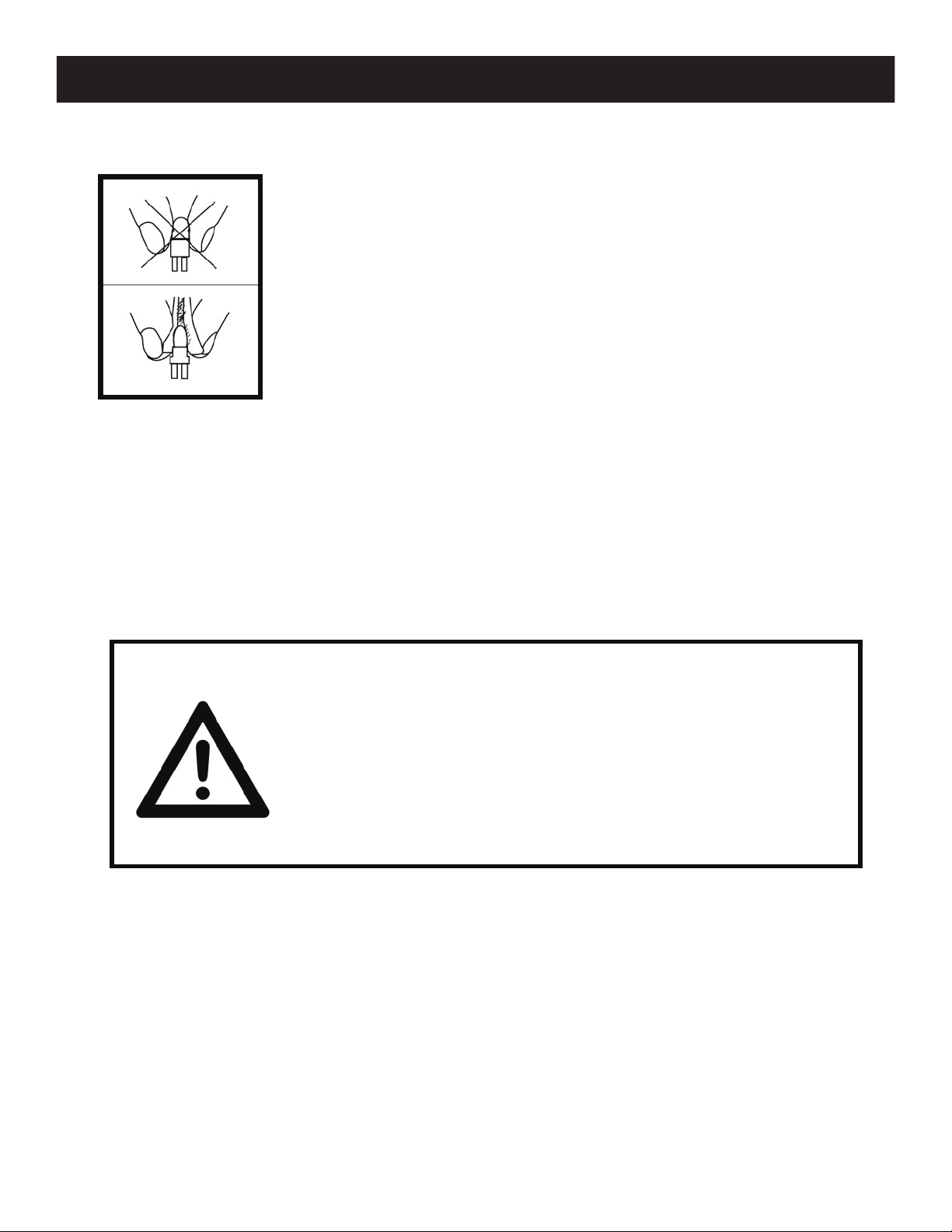
ALWAYS disconnect fixture from main power source before performing any type of service
and/or cleaning procedure. Only handle the power cord by the plug end; never pull out the
plug by tugging the wire portion of the cord.
During the initial operation of this fixture, a light smoke or smell may emit from the interior
of the fixture. This is a normal process and is caused by excess paint in the interior of the casing
burning off from the heat associated with the lamp and will decrease gradually over time.
ease.
Consistent operational breaks will ensure fixture will function properly for many years.
ONLY use the original packaging and materials to transport the fixture in for service.
ADJ Products, LLC - www.adj.com - Hydro Beam X1 User Manual Page 8
Page 10
Hydro Beam X1 Safety Guidelines
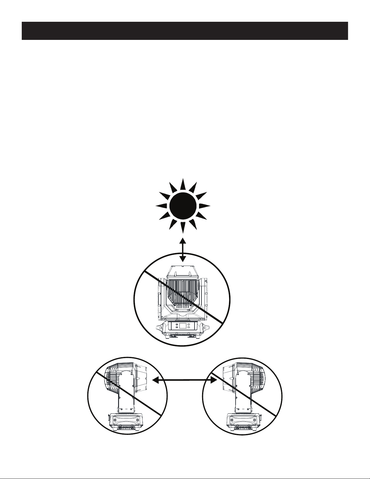
POTENTIAL INTERNAL FIXTURE DAMAGE FROM EXTERNAL SOURCES OF LIGHT BEAMS
External sources of light beams from direct sunlight, lighting moving head xtures, and lasers, which
are focused directly towards the exterior housing and/or penetrate the front lens opening of ADJ
lighting xtures, can cause severe internal damage including burning to optics, dichroic color lters,
glass and metal gobos, prisms, animation wheels, frost lters, iris, shutters, motors, belts, wiring,
discharge lamps, and LEDs.
This issue is not specic only to ADJ lighting xtures, it is a common issue with lighting xtures
from all manufacturers. Although there is no true way to fully prevent this issue from happening, the
guidelines below can prevent any potential damage from occurring if followed. Contact ADJ Service
for more details.
DO NOT EXPOSE THE FIXTURE AND/OR FRONT LENS OPENING TO LIGHT BEAMS FROM DIRECT
SUNLIGHT, OTHER LIGHTING MOVING HEAD FIXTURES, AND LASERS WHILE UNPACKING,
INSTALLATION, USE, AND EXTENDED IDLE TIMES OUTDOORS.
DO NOT FOCUS A LIGHT BEAM FROM ONE LIGHTING FIXTURE DIRECTLY TOWARDS ANOTHER.
ADJ Products, LLC - www.adj.com - Hydro Beam X1 User Manual Page 9
Page 11

Hydro Beam X1 Overview
8
7 9
10
1
1. Lens
2. MENU Button
3. ENTER Button
2
3 4 5
4. LCD Menu Control Display
5. DOWN Button
6
6. UP Button
7. Service Port
8. IP65 5-Pin DMX IN & IP65 5-Pin DMX OUT
9. Gore Valve
10. IP65 Power IN & IP65 Power Out
8
7 9
10
ADJ Products, LLC - www.adj.com - Hydro Beam X1 User Manual Page 10
Page 12
Hydro Beam X1 Discharge Lamp Warning
D I SCHARGE L A M P W ARNI N G
This fixture is fitted with a DISCHARGE LAMP, which is highly
susceptible to damage if improperly handled. NEVER touch the
lamp with your bare hands as the oil from your hands will shorten
the life of the lamp. Also, NEVER move the fixture until the lamp
has had ample time to cool. Lamps are NOT covered under
warranty conditions. Avoid switching the fixture ON and OFF
repeatedly in short intervals as this will reduce lamp life and
intensity. To achieve the intensity associated with discharge
lamps, these lamps use gas sealed in a high-pressure
environment to emit a brilliant output.
Due to the high pressure involved with the construction of the lamp, the lamp MAY
EXPLODE DURING PROLONGED EXTENSIVE USE. This risk is increased with age;
added care is encouraged when dealing with older lamps. Thus, the lamp must always
be replaced at the end of their recommended duty cycle. Extreme caution should be
used when operating this or any fixture fitted with a gas discharge lamp.
U V RADI ATI ON NOT I C E
This fixture emits intense UV radiation, which is harmful to the
eyes and skin.
severe damage to the retina. NEVER operate this fixture with
ANY of the protective covers removed. These covers have been
specially designed to shield against UV radiation.
The intense luminance of the lamp can cause
ADJ Products, LLC - www.adj.com - Hydro Beam X1 User Manual Page 11
Page 13

Hydro Beam X1 Discharge Lamp Warning
LAMP REPLACEMENT WARNING
When the lamp reaches 5700 Hours of usage, the display wll ash the message “Replace LampSoon”. This
message will ash for up to 10 minutes. To conrm this warning and return to normal operation, press
the ENTER button.
When the lamp reaches 6000 Hours of usage, the display wll ash the message “Replace LampNow”.
This message will ash for up to 10 minutes. To conrm this warning and return to normal operation,
press the ENTER button. NOTE: When the xture is powered OFF and then back ON again, the
xture display will ash the following message: “Replace LampNow”.
When the lamp reaches 6200 Hours of usage, the display again wll ash the message “Replace LampNow”.
The unit will now NO longer respond to DMX commands and enter hibernation mode which will
discontinue all xture functionality with the exception of a few menu commands.The xture will
continue to enter into hibernation mode until the lamp is replaced and the lamp time (LAMP ON TIME-R) has
been reset. See page 31 “LAMP ON TIME-R” under the “TOTAL LAMP TIME” submenu.
NOTE: After replacing the lamp, the lamp time MUST be reset. The lamp time must be reset to
gain access to the full system menu.
Lamp Life may vary depending on several factors including but not limited to:
Enviromental Conditions, Power/Voltage, Usage Patterns (On-O Cycling), Control,
and Dimming.
ADJ Products, LLC - www.adj.com - Hydro Beam X1 User Manual Page 12
Page 14

Hydro Beam X1 Lamp Installation
LAMP INSTALLATION/REPLACEMENT
WARNING! LAMP REPLACEMENT SHOULD ONLY BE DONE BY A TRAINED TECHNICIAN.
1. Turn OFF power and allow approximately 60 minutes for the xture to cool down.
2. Unscrew the (4x) allen head screws to remove the rear cover. When removing the rear cover,
please be advised that the cover is connected to the unit via a safety cable and connected wire
cable.
3. Gently remove the (2x) spade terminals
connected to the lamp.
4. Use a at head screwdriver to turn the
lamp centering screw clockwise until the lamp
slides out of its holding mechanism on the
right side.
ADJ Products, LLC - www.adj.com - Hydro Beam X1 User Manual Page 13
Page 15

Hydro Beam X1 Lamp Installation
5. Using your ngers, gently pull back the 2 lamp holders, and carefully slide the lamp to the right and
out.
6. Slide the new lamp into its socket by pulling it leftwards against the 2 lamp holders. Use a at head
screwdriver and turn the lamp centering screw counter-clockwise to its original position.
7. Reconnect the (2x) spade terminals to the lamp and replace the cover and tighted the (4x) allen head
screws.
ADJ Products, LLC - www.adj.com - Hydro Beam X1 User Manual Page 14
Page 16

Hydro Beam X1 Torque Settings & IP Tester
TORQUE SETTINGS FOR SCREWS
ALL SCREWS MUST BE TIGHTENED WITH A TORQUE DRIVER. All screws are Allen
Head screws. Please see below for screw locations, screw quantity and torque settings. The
number listed in the “#” column corresponds to the location on the xture. See the xture
diagram and number on the next page for screw location depictions.
SCREW LOCATIONS TORQUE SETTING & TOOL SIZE#
1 Lens Assembly to Head Casting (x6) 6.5-8.7 In-Lb / 3mm Hex
2 Lamp Cover to Head Casting (x4) 6.5-8.7 In-Lb / 3mm Hex
3 Yoke Arm Cover to Yoke Frame (8 x Each Side = 16 Total) 6.5-8.7 In-Lb / 3mm Hex
4 Access Cover to Yoke Frame (x4) Manual Screwdriver / 3mm Hex
5 Handle to Base Casting (2 x Each Side = 4 Total) Fasten by Air Screwdriver / 5mm Hex
6 Bottom Cover to Base Casting (x12) 6.7-9.6 In-Lb / #2 Phillips
7 Power & Data Connector to Base Casting (x10) 6.5-8.7 In-Lb / #2 Phillips
8 1/4 Turn Adaptor Plate to Bottom Cover (x14) 6.5-8.7 In-Lb / #2 Phillips
TORQUE DRIVERS (Recommended):
UTICA TS-30 (Shown)
ALTERNATIVE DRIVERS:
Proto J6107A
Wiha 28887
CAUTION! DO NOT OVER TORQUE SCREWS AS THIS CAN CAUSE LEAKAGE ISSUES!
TO CONFIRM THE IP65 INTENGRITY AFTER A LAMP REPLACEMENT, TEST THE FIXTURE
USING THE ELATION IP TESTER. CONTACT ELATION SERVICE FOR MORE DETAILS.
ADJ Products, LLC - www.adj.com - Hydro Beam X1 User Manual Page 15
Page 17

Hydro Beam X1 Screw Locations
1
4
2
7
6
8
3
6
6
8
5
6
ADJ Products, LLC - www.adj.com - Hydro Beam X1 User Manual Page 16
Page 18

Hydro Beam X1 Fixture Installation
F I XTU R E I N S T A LLA T I O N
Keep fixture at least 5.0 feet (1.5m) away from any
flammable materials, decorations, pyrotechnics, etc.
ELEC TRI C AL CONNE C T I ONS
A q ualif i e d el ectri ci an sho u ld b e used f o r all
el ectri cal c o nnect ions and/ or inst a llat i o ns.
MINIMUM DISTANCE TO OBJECTS/SURFACES
M UST BE 40 F EET ( 12 M E T ERS)
FLAMMA B LE M ATER I AL W A RNI N G
MAXIMUM TEMPERATURE OF EXTERNAL SURFACE
212° F ( 100° C )
DO NOT INSTALL THE FIXTURE IF YOU ARE NOT QUALIFIED TO DO SO!
Fixture MUST be installed following all local, national, and country commercial electrical and
construction codes and regulations. Before rigging/mounting the fixture to any metal
truss/structure or placing the fixture on any surface, a professional equipment installer
MUST be consulted to determine if the metal truss/structure or surface is properly certified
to safely hold the combined weight of the fixture, clamps, cables, and accessories.
Overhead fixture installation must always be secured with a secondary safety attachment,
such as an appropriately rated safety cable that meets all local, national, and country codes
and regulations.
Fixture ambient operating temperature range is -4° to 113°F. (-20° to 45°C)
Do not use this fixture outside this temperature range.
Fixture should be installed in areas outside walking paths, seating areas, or away from areas
were unauthorized personnel might reach the fixture by hand.
NEVER stand directly below the fixture when rigging, removing, or servicing.
Allow approximately 60 minutes for the fixture to cool down before servicing.
ADJ Products, LLC - www.adj.com - Hydro Beam X1 User Manual Page 17
Page 19

Hydro Beam X1 Fixture Installation
NOTICE: The suitable enviromental temperature for this lighting xture is between -25˚ C to 45˚ C.
Do not place this lighting xture in an enviroment where the temperatures are under or above the
temperatures stated above. This will allow the xture to run at its best and help prolong the xture
life.
Screw one clamp via a M12 screw and nut into the Omega holder. Insert the quick-lock fasteners of
the Omega holder into the respective holes of the adjustable mounting bracket. Tighten the quick-lock
fasteners fully clockwise. Pull the safety-cable through the opening(s) located on the bottom of the
unit and over the trussing system or a safe xation spot. Insert the end in the carabine and tighten
the safety screw.
CLAMP AND OMEGA
BRACKET SET UP
SAFETY CABLE
ATTACHMENT POINTS
SAFETY CABLE
OMEGA BRACKET
ATTACHMENT POINTS
CLAMP
OMEGA BRACKET
ADJ Products, LLC - www.adj.com - Hydro Beam X1 User Manual Page 18
Page 20

Hydro Beam X1 Fixture Installation
When installing the unit, the trussing or area of installation must be able to hold 10 times the weight
without any deformation. When installing the unit must be secured with a secondary safety attachment,
e.g. and appropriate safety cable. Never stand directly below the unit when mounting, removing, or
servicing the unit.
Overhead mounting requires extensive experience, including calculating working load limits, installation
material being used, and perodic safety inspection of all installation material and unit. If you lack
these qualications, do not attempt the installation yourself.
These installaiton should be checked by a skilled person once a year.
LCD DISPLAY
CABLES
DOWN
* S I D E M OUNT I N G
TO MAINTAIN IP65 RATING INTEGRITY, FIXTURE
MUST BE INSTALLED WITH CABLES FACING THE
GROUND AT ALL TIMES. WATER MUST EASILY
RUN OFF AND NOT COLLECT AROUND CABLE
CONNECTIONS.
LCD DISPLAY
CABLES
DOWN
* S A FETY CABL E
ALWAYS ATTACH A SAFETY CABLE WHENEVER
INSTALLING THIS FIXTURE IN A SUSPENDED
ENVIRONMENT TO ENSURE THE FIXTURE WILL
NOT DROP IF THE CLAMP FAILS.
The Hydro Beam X1 is fully operational in three dierent mounting positions, hanging upside-down,
mounted sideways on trussing, or set on a at level surface. Be sure this xture is kept at least 12m
(40ft) away from any ammable materials (decoration etc.). Always use and install the supplied safety
cable as a safety measure to prevent accidental damage and/or injury in the event the clamp fails
(see next page). Never use the carrying handles for secondary attachment.
ADJ Products, LLC - www.adj.com - Hydro Beam X1 User Manual Page 19
Page 21

Hydro Beam X1 Connections
ENSURE ALL CONNECTIONS AND END CAPS ARE PROPERLY SEALED WITH A DIELECTRIC
GREASE (AVAILABLE AT MOST ELECTRICAL SUPPLIERS) TO PREVENT WATER CORROSION
AND/OR ELECTRICAL SHORT CIRCUIT.
TO MAINTAIN IP65 RATING INTEGRITY AND PREVENT WATER FROM ENTERING THE FIXTURE,
ALL UNUSED CONNECTION RUBBER CAPS MUST BE SEALED.
ADJ Products, LLC - www.adj.com - Hydro Beam X1 User Manual Page 20
Page 22

Hydro Beam X1 DMX Set Up
DMX-512: DMX is short for Digital Multiplex. This is a universal protocol used as a form of communication
between intelligent fixtures and controllers. A DMX controller sends DMX data instructions from
the controller to the fixture. DMX data is sent as serial data that travels from fixture to fixture via the
DATA “IN” and DATA “OUT” XLR terminals located on all DMX fixtures (most controllers only have a
DATA “OUT” terminal).
DMX Linking: DMX is a language allowing all makes and models of dierent manufactures to be
linked together and operate from a single controller, as long as all xtures and the controller are DMX
compliant. To ensure proper DMX data transmission, when using several DMX fixtures try to use
the shortest cable path possible. The order in which fixtures are connected in a DMX line does not
influence the DMX addressing. For example; a fixture assigned a DMX address of 1 may be placed
anywhere in a DMX line, at the beginning, at the end, or anywhere in the middle. When a fixture is
assigned a DMX address of 1, the DMX controller knows to send DATA assigned to address 1 to that
unit, no matter where it is located in the DMX chain.
Data Cable (DMX Cable) Requirements (For DMX Operation): The Hydro Beam X1 can be controlled via
DMX-512 protocol. Your unit and your DMX controller requires a 5-pin XLR connector for data input and data
output. We recommend Accu-Cable DMX cables. If you are making your own cables, be sure to use
standard 110-120 Ohm shielded cable (This cable may be purchased at almost all pro lighting stores).
Your cables should be made with a male and female XLR connector on either end of the cable. Also
remember that DMX cable must be daisy chained and cannot be split.
Special Note: Line Termination.
on the last unit to avoid erratic behavior. A terminator is a 110-120 ohm 1/4 watt resistor which is connected between pins 2 and 3 of a male XLR connector (DATA + and DATA -). This unit is inserted in the
female XLR connector of the last unit in your daisy chain to terminate the line. Using a cable terminator
(ADJ part number Z-DMX/T) will decrease the possibilities of erratic behavior.
TO MAINTAIN IP65 RATING INTEGRITY AND PREVENT WATER FROM ENTERING THE FIXTURE,
ALL UNUSED CONNECTION RUBBER CAPS MUST BE SEALED AND ONLY IP65 RATED POWER
AND DATE CABLES MUST BE USED.
When longer runs of cable are used, you may need to use a terminator
ADJ Products, LLC - www.adj.com - Hydro Beam X1 User Manual Page 21
Page 23

Hydro Beam X1 DMX Addressing
DMX ADDRESSING
All xtures should be given a DMX starting address when using a DMX controller, so the correct xture
responds to the correct control signal. This digital starting address is the channel number from which
the xture starts to “listen” to the digital control signal sent out from the DMX controller. The assignment
of this starting DMX address is achieved by setting the correct DMX address on the digital control
display on the xture.
You can set the same starting address for all xtures or a group of xtures, or set dierent addresses
for each individual xture. Setting all xtures to the same DMX address will cause all xtures to react
in the same way, in other words, changing the settings of one channel will aect all the xtures
simultaneously.
If you set each xture to a dierent DMX address, each unit will start to “listen” to the channel number
you have set, based on the quantity of DMX channels of each xture. That means changing the settings
of one channel will only aect the selected xture.
In the case of the Hydro Beam X1, when in 11 Channel you should set the starting DMX address of
the rst unit to 1, the second unit to 12 (11 + 1), the third unit to 23 (12 + 11), and so on. (See the chart
below for more details.)
Channel Mode
11 Channels 1 12 23 34
14 Channels 1 15 29 43
Unit1
Address
Unit2
Address
Unit3
Address
Unit4
Address
ADJ Products, LLC - www.adj.com - Hydro Beam X1 User Manual Page 22
Page 24

Hydro Beam X1 DMX Channel Modes
11 Channels 14 Channels Values
1 1
2
2 3
4
3 5
000-255
000-255
000-255
000-255
000-002
003-004
005-006
007-008
009-010
011-012
013-014
015-016
017-018
019-021
022-023
024-025
026-027
028-029
030-031
032-033
034-035
036-037
038-039
040-042
043-044
045-046
047-048
049-050
051-052
053-054
055-056
057-058
059-060
061-063
064-127
128-189
190-193
194-255
Functions
PAN MOVEMENT (8-BIT):
0˚-540˚
PAN FINE (16-BIT):
Fine Control of Pan Movement
TILT MOVEMENT (8-BIT):
0˚-270˚
TILT MOVEMENT (16-BIT):
Fine Control of Tilt Movement
COLOR WHEEL:
Open / White
White + Red
Red
Red + Blue
Blue
Blue + Green
Green
Green + Yellow
Yellow
Yellow + Orange
Orange
Orange + Magenta
Magenta
Magenta + Light Blue
Light Blue
Light Blue + Light Yellow
Light Yellow
Light Yellow + Light Green
Light Green
Light Green + Purple
Purple
Purple + Pink
Pink
Pink + Medium Yellow
Medium Yellow
Medium Yellow + CTB
CTB
CTB + UV
UV
UV + White
Indexing
Clockwise Rotation Fast-Slow
Stop
Counter-Clockwise Rotation Slow-Fast
ADJ Products, LLC - www.adj.com - Hydro Beam X1 User Manual Page 23
Page 25

Hydro Beam X1 DMX Channel Modes
11 Channels 14 Channels Values
000-003
004-007
008-011
012-015
016-019
020-023
024-027
028-031
032-035
036-039
040-043
044-047
048-051
052-055
056-059
4 6
5 7
060-063
064-068
069-072
073-076
077-080
081-084
085-089
090-093
094-097
098-101
102-105
106-110
111-114
115-118
119-122
123-127
128-189
190-193
194-255
000-007
008-255
Functions
GOBO WHEEL:
Open
Gobo 1
Gobo 2
Gobo 3
Gobo 4
Gobo 5
Gobo 6
Gobo 7
Gobo 8
Gobo 9
Gobo 10
Gobo 11
Gobo 12
Gobo 13
Gobo 14
Gobo 15
Gobo 1 Shake
Gobo 2 Shake
Gobo 3 Shake
Gobo 4 Shake
Gobo 5 Shake
Gobo 6 Shake
Gobo 7 Shake
Gobo 8 Shake
Gobo 9 Shake
Gobo 10 Shake
Gobo 11 Shake
Gobo 12 Shake
Gobo 13 Shake
Gobo 14 Shake
Gobo 15 Shake
Counter-Clockwise Rotation Fast-Slow
Stop
Clockwise Rotation Slow-Fast
PRISM (16 FACET CIRCULAR):
Close
Open
ROTATING PRISM:
Indexing
Counter-Clockwise Rotation Fast-Slow
Stop
Clockwise Rotation Slow-Fast
SHUTTER & STROBING:
Shutter Closed
Strobing Slow-Fast
Shutter Open
Pulse Effect in Slow-Fast
Shutter Open
Strobing at Low Frequency
Strobing at Medium Frequency
Strobing at High Frequency
Open
6 8
7 9
000-127
128-189
190-193
194-255
000-003
004-103
104-107
108-207
208-212
213-225
226-238
239-251
252-255
ADJ Products, LLC - www.adj.com - Hydro Beam X1 User Manual Page 24
Page 26

Hydro Beam X1 DMX Channel Modes
11 Channels 14 Channels Values
8 10
9
10
11
11
12
13
14
000-255
000-255
000-007
008-255
000-255
000-129
130-139
140-149
150-159
160-199
200-209
210-229
230-239
240-255
Functions
DIMMER:
0%-100%
DIMMER FINE:
0%-100%
FROST:
Close
Open
PAN/TILT MOVEMENT SPEED
Fast-Slow
SPECIAL FUNCTIONS:
Null
Lamp On
Reset Pan/Tilt Motors
Reset Effect Motor
Null
Reset All Motors
Null
Lamp Off
Null
Hydro Beam X1 Gobos
Gobo 4Gobo 1 Gobo 2 Gobo 3
Gobo 5 Gobo 6 Gobo 7 Gobo 8 Gobo 9
Gobo 10 Gobo 11 Gobo 13 Gobo 14 Gobo 15Gobo 12
ADJ Products, LLC - www.adj.com - Hydro Beam X1 User Manual Page 25
Page 27

Hydro Beam X1 System Menu
SYSTEM MENU
The xture includes an easy to navigate system menu control panel display where all necessary
settings and adjustments are made. (See image below) During normal operation, pressing the MENU
button once will access the xture’s main menu. Once in the main menu, you can navigate through
the dierent functions and access the sub-menus with the UP and DOWN buttons. When you reach
a eld that requires adjusting, press the ENTER button to access that eld and use the UP and
DOWN buttons to adjust the eld. Pressing the ENTER button once more will conrm your setting.
You may exit the main menu at any time without making any adjustments by pressing the MENU
button.
ADJ Products, LLC - www.adj.com - Hydro Beam X1 User Manual Page 26
Page 28

Hydro Beam X1 System Menu
MENU OPTIONS DESCRIPTIONSUBMENU
DMX SETTINGS
PERSONALITY
DMX Address
DMX CH Mode
No DMX Status
Select Signal
Status Settings
WiFly Settings
001-XXX
11Ch / 14Ch
Hold Last / Blackout / Manual
DMX
WiFly Control via WiFly
WiFly / DMX Out
Pan Invert: On / Off
Tilt Invert: On / Off
P/T Feedback: On / Off
Pan Degree: 540
P/T Speed: Speed 1 / Speed 2
Hibernation: Off / 01M~99M / 15M
Set WiFly Channel: 00~14
Enable / Disable
Reset All Motors: Yes / No
Pan/Tilt Reset: Yes / No
DMX Addressing
DMX Channel Mode
Selection
DMX Lost Status
Control via DMX
Control via WiFly and send
DMX Out via DMX cable
Reverse Pan Motion
Reverse Tilt Motion
Pan/Tilt Movement Feedback
Pan Degree
Pan/Tilt Movement Speed
Sleep Setting (No Activity)
Set WiFly Wireless Channel
Activate/Deactivate WiFly
Reset All Motors
Reset the Pan & Tilt Motors
MANUAL
CONTROL
Reset Motors
Display
Service
(Passcode = 050)
Pan
Tilt
Color
Gobo
Prism
RPrism
Shutter
Dimmer
Frost
Color Reset: Yes / No
Gobo: Yes / No
Prism/R-P Reset: Yes / No
Shutter Reset: Yes / No
Frost Reset: Yes / No
Intensity: 1~10 (Dimmest-Brightest)
Display Invert: Yes / No
Screen Saver Delay: Off~10 Minutes
Display Lock: On / Off Display Lock
Calibration: Passcode = 050
USB Port Power: On / Off
Update Software
Factory Restore: Yes / No - Passcode = 011
000-255
000-255
000-255
000-255
000-255
000-255
000-255
000-255
000-255
Reset the Color Wheel Motor
Reset the Gobo Wheel Motor
Reset the Prism Motors
Reset the Shutter Motor
Reset the Frost Motor
Display Brightness
Display Readout Inversion
Display Shutoff Time
Calibration Adjustment
Restore Factory Settings
Manual Control
ADJ Products, LLC - www.adj.com - Hydro Beam X1 User Manual Page 27
Page 29

Hydro Beam X1 System Menu
MENU OPTIONS DESCRIPTIONSUBMENU
Total Running Time
(Not Resettable)
Total Running Time
(Resettable)
Reset P-On Time-R
(Total Running Time)
Fixture Life Time
Power On Time: XXXXXX Hours
P-On Time-R: XXXXXX Hours
P-On Time Reset: Passcode = 050
INFORMATION
Total Lamp Time
Fixture Temps
Lamp On Time - XXXXXX Hours
Lamp On Time-R: XXXXXX Hours
Lamp On Time Reset: Passcode = 050
Current: XXX ˚F / XXX ˚C
Max Resettable: XXX ˚F / XXX ˚C
Head
Max Not Resettable: XXX ˚F / XXX ˚C
Current: XXX ˚F / XXX ˚C
Max Resettable: XXX ˚F / XXX ˚C
Base
Max Not Resettable: XXX ˚F / XXX ˚C
Reset Head Temp: Yes / No - Passcode = 050
Reset Base Temp: Yes / No - Passcode = 050
Lamp On Time
(Not Resettable)
Lamp On Time
(Resettable)
Reset Lamp On Time-R
(Lamp On Time)
Current Head Temperature
Maximum Temperature
(1)
Reached (Resettable)
(See Note 1)
Maximum Temperature
(2)
Reached (Not Resettable)
(See Note 2)
Current Base Temperature
Maximum Temperature
(1)
Reached (Resettable)
(See Note 1)
Maximum Temperature
(2)
Reached (Not Resettable)
(See Note 2)
Reset Head Temperature
(Max Resettable)
Reset Base Temperature
(Max Resettable)
Humidity
Fan Info. (RPM)
DMX Values
(See Note 3)
(3)
Head Humidity: XXX%
Base Humidity: XXX%
Lamp Fan: XXX
Head Fan 1: XXX
Head Fan 2: XXX
Head Fan 3: XXX
Head Fan 4: XXX
Base Fan: XXX
Pan / Pan Fine / Tilt / Tilt Fine / Color / Gobo /
Prism / RPrism / Shutter / Dimmer /
Dimmer Fine / Frost / P/T Speed / Spe. Func
Fixture Errors (Listed Errors One by One)
Current Head Humidity
Current Base Humidity
Lamp Fan Speed
Head Fan Speed
Head Fan Speed
Head Fan Speed
Head Fan Speed
Base Fan Speed
Current DMX Values
Last 10 Fixture Error Codes
Error Logs
Reset Error Log: Yes / No (Pass Code = 050)
Clear the Error Log
Software Version Current Software VersionVX.XX
ADJ Products, LLC - www.adj.com - Hydro Beam X1 User Manual Page 28
Page 30

Hydro Beam X1 System Menu
MENU OPTIONS DESCRIPTIONSUBMENU
Lamp ON / OFF
LAMP CONTROL
Notes:
(1) Current Maximum Temperature - Maximum fixture temp. that has been recorded, before reset and after reset.
(2) Maximum Temperature - Overall maximum fixture temp. that has been recorded. (Not Resettable).
(3) DMX Value options depend on the DMX Channel mode setting.
Lamp ON
with Power
Lamp ON via DMX On / Off
Lamp OFF via DMX On / Off
On / Off
On / Off
Lamp On/Off
Lamp ON when Power ON
Lamp Power ON via DMX
Lamp Power OFF via DMX
ADJ Products, LLC - www.adj.com - Hydro Beam X1 User Manual Page 29
Page 31

Hydro Beam X1 System Menu
System Menu: When making adjustments press ENTER to conrm your setup. To exit without
making any adjustments press the MENU button. The display will lock after 30 seconds, press
the MENU button for 3 seconds to unlock.
DMX SETTINGS - The submenus listed under DMX SETTINGS are as follows: DMX Address, DMX
Channel Mode, No DMX Status, and Select Signal.
- DMX ADDRESS - In this submenu you can use the UP or DOWN buttons to adjust and nd your
desired DMX address.
- DMX CHANNEL MODE - In this submenu you can use the UP or DOWN buttons to nd your
desired DMX channel mode.
- NO DMX STATUS - This submenu setting is used as a precaution mode in case the DMX signal is
lost or interrupted. The operating mode chosen in this submenu is the running mode the xture
will go into when the DMX signal is lost. Listed below are the 3 modes.
• HOLD LAST - This setting will have the xture stay in the last DMX setup.
• BLACKOUT - This setting will have the xture automatically go into stand by mode.
• MANUAL - This setting will go into the current manual control set up. See MANUAL CONTROL.
PERSONALITY - The submenus listed under PERSONALITY are as follows: Select Signal, Status
Settings, WiFly Settings, Reset Motors, Display, and Service.
- SELECT SIGNAL - In this submenu you can select your desired DMX control mode:
• DMX - Control the unit via DMX cable connection.
• WiFly - Control the unit via WiFly.
• WiFly / DMX Out - Control the unit via WiFly connection. The DMX signal is sent to the next unit
via DMX cable.
- STATUS SETTINGS - In this submenu you are able to access and adjust/change: Pan Invert, Tilt
Invert, P./T. Feedback, Pan Degree (no adjustment), P./T. Speed, and Hibernation.
- WIFLY SETTINGS - In this submenu you are able to access and adjust/change: WiFly Channel setting
and Enable/Disable WiFly.
- RESET MOTORS - In this submenu you are able to reset selected motors.
- DISPLAY - In this submenu you are able to access and adjust/change: Backlight Intensity, Display
Invert, Screen Saver Delay, and Display Lock.
- SERVICE - In this submenu you are able to access and adjust/change: calibration setting, USB
power activation, update the software, and restore the factory settings.
MANUAL CONTROL - This menu is for manual testing and manual control. Pan, tilt, color wheel,
gobo wheel, prism, prism rotation, shutter, dimmer, and frost can all be tested/adjusted.
ADJ Products, LLC - www.adj.com - Hydro Beam X1 User Manual Page 30
Page 32

Hydro Beam X1 System Menu
INFORMATION - The submenus listed under INFORMATION are as follows: Fixture Life Time,
Total Lamp Time, Fixture Temps, Humidity, Fan Info. (RPM), DMX Values, Error Logs, and Software
Version.
- FIXTURE LIFE TIME
• Power On Time -The TOTAL power ON running time of the unit is displayed. This time CANNOT
be reset. Reminder: The displayed time represents the TOTAL POWER ON time.
• P-On Time-R - The CURRENT power ON running time of the unit is displayed. This running time
may not be the same as the total power ON running time displayed under “Power On Time”. This
time CAN be reset. Reminder: The displayed time represents the CURRENT POWER ON TIME
since the last reset.
• P-On Time Reset - Reset the CURRENT power ON running time that is displayed under “P-On Time-R”.
- TOTAL LAMP TIME
• Lamp On Time - The TOTAL Lamp ON time is displayed. This total lamp ON time CANNOT be
reset. Reminder: The displayed time represents the TOTAL LAMP ON time.
• Lamp On Time-R - The CURRENT LED ON running time is displayed. This running time may not
be the same as the total lamp ON time displayed under “Lamp On Time”. This total lamp ON
time CAN be reset. Reminder: The displayed time represents the CURRENT LAMP ON time
since the last reset.
• Lamp On Time Reset - With this function you can reset the CURRENT lamp ON time that is displayed
under “Lamp On Time-R”.
- FIXTURE TEMPS
• Head
Current - Current temperature of the moving head is displayed.
Max Resettable - Maximum moving head temperature that has been recorded, before reset
and after reset. (Resettable)
Max Not Resettable - Overall maximum moving head temperature that has been recorded.
(Not Resettable)
• Base
Current - Current temperature of the base is displayed.
Max Resettable - Maximum base temperature that has been recorded, before reset and after
reset. (Resettable)
Max Not Resettable - Overall maximum base temperature that has been recorded.
(Not Resettable)
• Reset Head Temp - Reset the “MAX RESETTABLE” moving head temperature. (Pass Code is “50”)
• Reset Base Temp - Reset the “MAX RESETTABLE” base temperature. (Pass Code is “50”)
- HUMIDITY
Head Humidity - The current humidity of the moving head is displayed.
Base Humidity - The current humidity of the base is displayed.
ADJ Products, LLC - www.adj.com - Hydro Beam X1 User Manual Page 31
Page 33

Hydro Beam X1 System Menu
- FAN INFO. (RPM)
Lamp Fan - Current speed of the LED fan is displayed.
Head Fan 1 - Current speed of the moving head fan 1 is displayed.
Head Fan 2 - Current speed of the moving head fan 2 is displayed.
Head Fan 3 - Current speed of the moving head fan 3 is displayed.
Head Fan 4 - Current speed of the moving head fan 4 is displayed.
Base Fan - Current speed of the base fan is displayed.
- DMX Values - Displays the DMX values of any DMX channel that is currently in use.
NOTE: DMX Value options depend on the DMX Channel mode setting.
- Error Logs - Displays any error codes.
- Software Version - Current software version is displayed.
LAMP CONTROL - The submenus listed under LAMP CONTROL are as follows: Lamp ON/OFF,
Lamp ON with Power, Lamp ON via DMX, and Lamp OFF via DMX.
- Lamp ON/OFF - Turn the lamp On/O.
- Lamp ON with Power - Lamp powers “ON” when power is applied.
- Lamp ON via DMX - Power lamp “ON” using a DMX controller.
- Lamp OFF via DMX - Power lamp “OFF” using a DMX controller.
ADJ Products, LLC - www.adj.com - Hydro Beam X1 User Manual Page 32
Page 34

Hydro Beam X1 WiFly Control
BEFORE SETTING THE WIRELESS CHANNEL ON ANY WIFLY FIXTURE, MAKE SURE
THE SOURCE WIFLY WIRELESS DMX TRANSCEIVER DEVICE IS OFF.
With this feature you are able to control the unit with DMX without the need of XLR cables. Your
DMX controller must be connected to a ADJ WiFly Transceiver to use this function. You are able to
communicate up to 2500 feet/760 meters (open line of sight).
1. Ensure the source WiFly wireless DMX Transceiver device is powered OFF.
2. Power ON the fixture and using the control panel scroll to the PERSONALITY menu and press
ENTER. Use the UP and DOWN buttons to highlight the WIFLY SETTINGS submenu and press
ENTER.
3. Using the UP and DOWN buttons, highlight ENABLE/DISABLE WIFLY. Press the ENTER button
to toggle between ENABLE & DISABLE. Press ENTER so that “ENABLE” is displayed.
4. Next highlight SET WIFLY CHANNEL and press ENTER. Use the UP and DOWN buttons to find
your desired WiFly address and press ENTER to confirm.
NOTE: Erratic fixture movement may occur if other WiFly wireless DMX products are in use in
the same area and are using the same WiFly wireless channel. When WiFly is enabled, the fixture
may immediately start to respond to the DMX wireless signal from another WiFly wireless DMX
Transceiver. Make sure to know what WiFly wireless channels are being used in the area where the
fixture is being used.
ADJ WIFLY WIRELESS TRANSCEIVER only has 0-14 wireless channels, NO CH 15.
5. Press the MENU button to exit out of the WIFLY SETTINGS submenu. Press the UP button so
that SELECT SIGNAL is highlighted and press ENTER. Press the DOWN button to highlight
WIFLY and press ENTER. Select YES and press ENTER to confirm.
6. Set your desired DMX address in the DMX ADDRESS submenu of the DMX SETTINGS main system
menu. Set your desired DMX channel mode in the DMX CH MODE submenu of the DMX SETTINGS
main system menu.
7. Repeat this process for all WiFly compatible fixtures in the WiFly wireless network, making sure
all fixtures are assigned the same WiFly wireless channel.
8. After all fixtures in the WiFly wireless network have been set to the same WiFly wireless channel
and powered ON, power ON the source WiFly DMX Transceiver device.
4. Test all fixtures connected to the WiFly wireless network to confirm proper functionality.
ADJ Products, LLC - www.adj.com - Hydro Beam X1 User Manual Page 33
Page 35

Hydro Beam X1 WiFly Control
WIRELESS WIFLY INSTALLATION LOCATION GUIDELINES
Wireless DMX signal can penetrate walls, glass, metal, and most objects. However, there are many
factors that can aect and/or interrupt the wireless DMX signal, one of which is people. Therefore, it
is highly recommended to position the wireless antenna a minimum of 9.8 ft. (3m) above audiences
and/or above ground level. Careful planning and testing of the selected installation location is critical
to ensure optimum and reliable wireless DMX operation.
9.8 ft (3m)
Above Ground
ADJ Products, LLC - www.adj.com - Hydro Beam X1 User Manual Page 34
Page 36

Hydro Beam X1 Error Codes
1
2
3
4
5
6
7
8
9
10
11
12
Printerrormessage Description
Lamp Hot Power Off Lamp Hot Power Off
CPU-B Error CPU-B Error
CPU-C Error CPU-C Error
Pan Reset Error
Pan Encoder Error
Tilt Reset Error
Tilt Encoder Error
Color Reset Error Color :Reset Error
Gobo Reset Error Gobo :Reset Error
Lamp Fan 1 start Errors
Lamp Fan 1 stop Errors
Head Fan 1 start Errors
Pan :Reset Error
Pan : Encoder Error
Tilt :Reset Error
Tilt : Encoder Error
LampFan 1 Can’t Start
Lamp Fan 1 Can’t Stop
Head Fan 1 Can’t Start
13
14
15
16
17
18
19
20
21
22
23
Head Fan 1 stop Errors
Head Fan 2 start Errors
Head Fan 2 stop Errors
Head Fan 3 start Errors
Head Fan 3 stop Errors
Head Fan 4 start Errors
Head Fan 4 stop Errors
Base Fan 1 start Errors
Base Fan 1 stop Errors
Base Fan 2 start Errors
Base Fan 2 stop Errors
Head Fan 1 Can’t Stop
Head Fan 2 Can’t Start
Head Fan 2 Can’t Stop
Head Fan 3 Can’t Start
Head Fan 3 Can’t Stop
Head Fan 4 Can’t Start
Head Fan 4 Can’t Stop
Base Fan 1 Can’t Start
Base Fan 1 Can’t Stop
Base Fan 2 Can’t Start
Base Fan 2 Can’t Stop
ADJ Products, LLC - www.adj.com - Hydro Beam X1 User Manual Page 35
Page 37

Hydro Beam X1 Dimensional Drawings
*NOT TO SCALE
12.5” / 317mm
18.05” / 458mm
7.2” / 183mm
14.95” / 380mm
13.25” / 336mm
16.92” / 430mm
8.25” / 210mm
10.25” / 260.35mm
ADJ Products, LLC - www.adj.com - Hydro Beam X1 User Manual Page 36
Page 38

Hydro Beam X1 Multiple Unit Power Linking
With this feature you can connect the xtures to one another using the power cable input and
output sockets.
NOTE: USE CAUTION WHEN POWER LINKING OTHER FIXTURES AS THE POWER
CONSUMPTION OF OTHER MODEL FIXTURES MAY EXCEED THE MAX POWER OUTPUT ON
THIS FIXTURE! CHECK SILK SCREEN FOR MAX AMPS.
Hydro Beam X1 Cleaning
Due to fog residue, smoke, and dust cleaning the internal and external optical lenses must be carried out periodically to optimize light output.
1. Use normal glass cleaner and a soft cloth to wipe down the outside casing.
2. Clean the external optics with glass cleaner and a soft cloth every 20 days.
3. Always be sure to dry all parts completely before plugging the unit back in.
Cleaning frequency depends on the environment in which the fixture operates (i.e. smoke, fog residue,
dust, dew).
ADJ Products, LLC - www.adj.com - Hydro Beam X1 User Manual Page 37
Page 39

Hydro Beam X1 Limited Warranty (USA Only)
MANUFACTURER’S LIMITED WARRANTY
A. ADJ Products, LLC hereby warrants, to the original purchaser, ADJ Products, LLC products
to be free of manufacturing defects in material and workmanship for a prescribed period from
the date of purchase (see specific warranty period on reverse). This warranty shall be valid only if the
product is purchased within the United States of America, including possessions and
territories. It is the owner’s responsibility to establish the date and place of purchase by acceptable
evidence, at the time service is sought.
B. For warranty service you must obtain a Return Authorization number (RA#)
before sending back the product–please contact ADJ Products, LLC Service Department
at 800-322-6337. Send the product only to the ADJ Products, LLC factory. All
shipping charges must be pre-paid. If the requested repairs or service (including
parts replacement) are within the terms of this warranty, ADJ Products, LLC will pay return
shipping charges only to a designated point within the United States. If the entire instrument is
sent, it must be shipped in it’s original package. No accessories should be shipped with the product. If
any accessories are shipped with the product, ADJ Products, LLC shall have no liability whatsoever for
loss of or damage to any such accessories, nor for the safe return thereof.
C. This warranty is void if the serial number has been altered or removed; if the product is modified in any
manner which ADJ Products, LLC concludes, after inspection, affects the reliability of the product; if the
product has been repaired or serviced by anyone other than the ADJ Products, LLC factory unless prior
written authorization was issued to purchaser by ADJ Products, LLC; if the product is damaged because
not properly maintained as set forth in the instruction manual.
D. This is not a service contract, and this warranty does not include maintnance, cleaning or periodic check
up. During the period specified above, ADJ Products, LLC will replace defective parts at its expense
with new or refurbished parts, and will absorb all expenses for warranty service and repair labor by
reason of defects in material or workmanship. The sole responsibility of ADJ Products, LLC under this
warranty shall be limited to the repair of the product, or replacement thereof, including parts, at the sole
discretion of ADJ Products, LLC. All products covered by this warranty were manufactured after August
15, 2012, and bear indentifying marks to that effect.
E. ADJ Products, LLC reserves the right to make changes in design and/or improvements upon its products
without any obligation to include these changes in any products theretofore manufactured.
No warranty, whether expressed or implied, is given or made with respect to any accessory supplied with
products described above. Except to the extent prohibited by applicable law, all implied warranties made
by ADJ Products, LLC in connection with this product, including warranties of merchantability or fitness,
are limited in duration to the warranty period set forth above. And no warranties, whether expressed or
implied, including warranties of merchantability or fitness, shall apply to this product after said period
has expired. The consumer’s and/or Dealer’s sole remedy shall be such repair or replacement as is
expressly provided above; and under no circumstances shall ADJ Products, LLC be liable for any loss or
damage, direct or consequential, arising out of the use of, or inability to use, this product.
This warranty is the only written warranty applicable to ADJ Products, LLC Products and
supersedes all prior warranties and written descriptions of warranty terms and conditions heretofore
published.
MANUFACTURER’S LIMITED WARRANTY PERIODS:
•NonL.E.D.LightingProducts=1-year(365days)LimitedWarranty(Such as: Special Effect
Lighting, Intelligent Lighting, UV lighting, Strobes, Fog Machines, Bubble Machines, Mirror Balls, Par
Cans, Trussing, Lighting Stands etc. excluding LED and lamps)
•LaserProducts=1Year(365Days)LimitedWarranty(excluding laser diodes which have a 6 month
limited warranty)
•L.E.D.Products=2-year(730days)LimitedWarranty(excluding batteries which have a 180 day lim-
ited warranty). Note:2YearWarrantyonlyappliestopurchaseswithintheUnitedStates.
•StarTecSeries=1YearLimitedWarranty(excluding batteries which have a 180 day limited warranty).
•ADJDMXControllers=2Year(730Days)LimitedWarranty
ADJ Products, LLC - www.adj.com - Hydro Beam X1 User Manual Page 38
Page 40

Hydro Beam X1 Technical Specifications
Voltage: 100V ~ 240V/50~60Hz
IP Rating: IP65
Lamp: Osram Sirius HRI 100W Discharge Lamp
Lamp Hours: 6,000 Hour Average Lamp Life*
Color Temperature: 9000K
Power Draw: 235W
Weight: 36 lbs./ 16.3 kgs.
Dimensions: 13.25” (L) x 8.25” (W) x 18.05” (H)
336 x 210 x 458mm
Gobos: 15 Gobos + Open
Prisms: 16 Facet Circular)
DMX Channels: 2 DMX Modes: 11 / 14
Warranty: 2 Year (730 days)
* May vary depending on several factors including but not limited to:
Enviromental Conditions, Power/Voltage, Usage Patterns (On-O Cycling), Control, and Dimming.
Please Note: Specications and improvements in the design of this unit and this
manual are subject to change.
ADJ Products, LLC - www.adj.com - Hydro Beam X1 User Manual Page 39
 Loading...