

Page 1
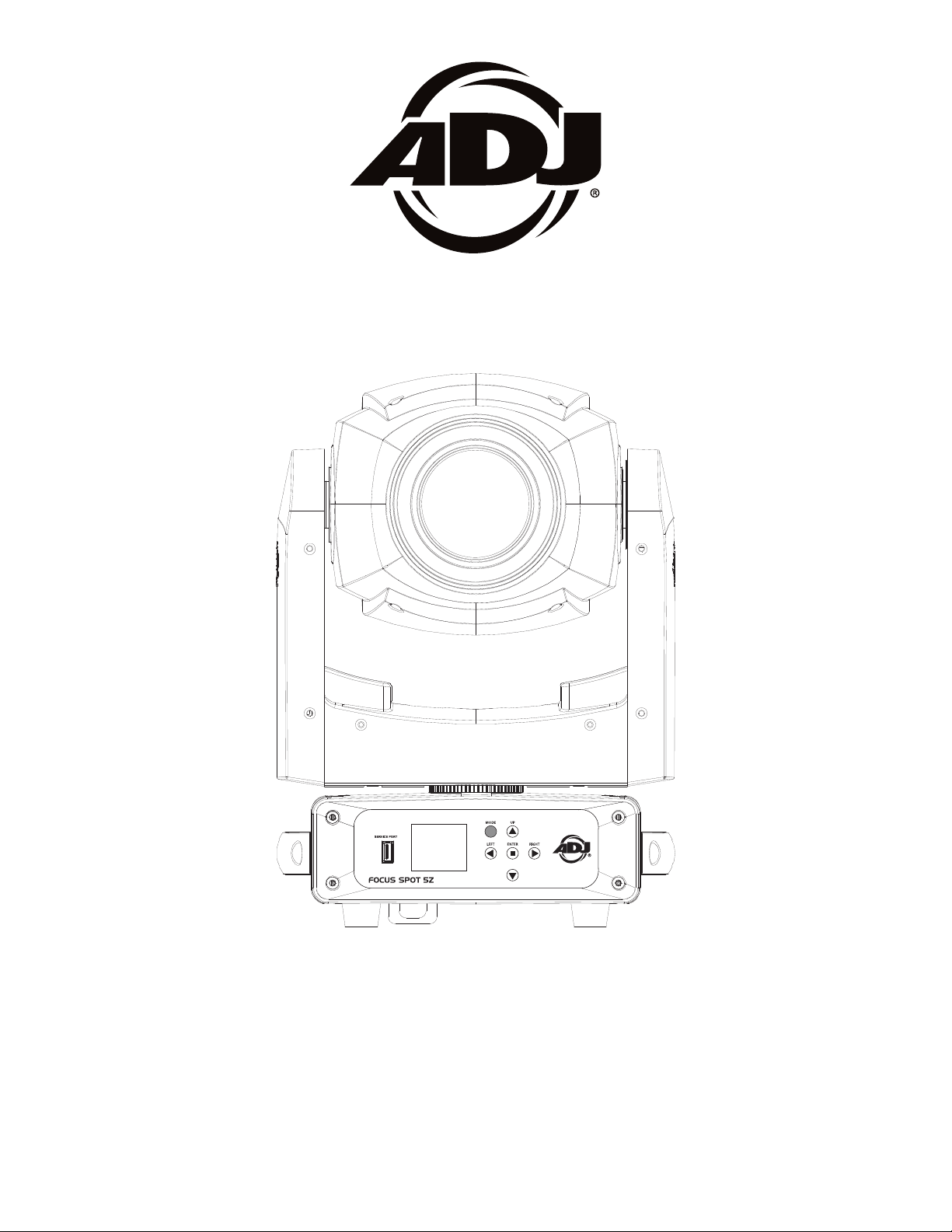
FOCUS SPOT 5Z
User Instructions
USA# FOC520
EU# 123000300
UPC# 818651028201
Page 2

©2020 ADJ Products, LLC all rights reserved. Information, specications, diagrams, images, and
FCC STATEMENT
This device complies with Part 15 of the FCC Rules. Operation is subject to the following two conditions:
(1) this device may not cause harmful interference, and (2) this device must accept any interference
received, including interference that may cause undesired operation.
FCC RADIO FREQUENCY INTERFERENCE WARNINGS & INSTRUCTIONS
This product has been tested and found to comply with the limits as per Part 15 of the FCC Rules. These
limits are designed to provide reasonable protection against harmful interference in a residential installation.
This device uses and can radiate radio frequency energy and, if not installed and used in accordance with
the included instructions, may cause harmful interference to radio communications. However, there is no
guarantee that interference will not occur in a particular installation. If this device does cause harmful
interference to radio or television reception, which can be determined by turning the device off and on, the
user is encouraged to try to correct the interference by one or more of the following methods:
· Reorient or relocate the device.
· Increase the separation between the device and the receiver.
· Connect the device to an electrical outlet on a circuit different from which the radio receiver is
connected.
· Consult the dealer or an experienced radio/TV technician for help.
instructions herein are subject to change without notice. ADJ Products, LLC logo and identifying
product names and numbers herein are trademarks of ADJ Products, LLC. Copyright protection
claimed includes all forms and matters of copyrightable materials and information now allowed by
statutory or judicial law or hereinafter granted. Product names used in this document may be
trademarks or registered trademarks of their respective companies and are hereby acknowledged.
All non-ADJ Products, LLC brands and product names are trademarks or registered trademarks of
their respective companies.
ADJ Products, LLC and all aliated companies hereby disclaim any and all liabilities for property,
equipment, building, and electrical damages, injuries to any persons, and direct or indirect economic
loss associated with the use or reliance of any information contained within this document, and/or as
a result of the impr
oper, unsafe, unsucient and negligent assembly, installation, rigging, and operation
of this product.
DOCUMENT VERSION
Due to additional product features and/or enhancements, an updated version of this document
may be available online.
Please check www.adj.com for the latest revision/update of this manual before beginning
installation and/or programming.
Date
05/13/20
08/06/
Europe Energy Saving Notice
Energy Saving Matters (EuP 2009/125/EC)
Saving electric energy is a key to help protecting the enviroment. Please turn o all electrical products when they are not in use. To avoid power consumption in idle mode, disconnect all electrical
equipment from power when not in use. Thank you!
Document
Version
20
1 1.0.3
1
.2
Software
Version >
1.0.5
DMX Channel Mode
19/22/26 Initial Version
No Change
Notes
Update Primary / Secondary
Page 3

Focus Spot 5Z Table of Contents
Introduction
Features I Warranty Registration
Safety Guidelines
Installation
Overview
DMX Set Up
DMX Addressing
DMX Modes & Values
System Menu
Dimmer Mode Chart I Dimmer Curve Chart
Dimensional Drawings
3
4
5
8
10
11
13
14
20
26
27
Gobo Replacement I Gobos
Fuse Replacement I Multiple Unit Power Linking
Trouble Shooting I Cleaning
Limited Warranty (USA Only)
Technical Specications
28
29
29
30
31
ADJ Products, LLC - www.adj.com - Focus Spot 5Z User Manual Page 2
Page 4

Focus Spot 5Z Introduction
Unpacking: Thank you for purchasing the Focus Spot 5Z
been thoroughly tested and has been shipped in perfect operating condition. Carefully check the
shipping carton for damage that may have occurred during shipping. If the carton appears to be
damaged, carefully inspect your fixture for any damage and be sure all accessories necessary to
operate the unit has arrived intact. In the case damage has been found or parts are missing, please
contact our toll free customer support number for further instructions. Do not return this unit to
your dealer without first contacting customer support.
Introduction: The Focus Spot 5Z is a DMX intelligent, moving head, LED fixture. This fixture can be
used in a stand alone mode or connected in a Primary/Secondary configuration. This product is
intended to be used by professionally trained personnel only and is not suitable for private use.
Customer Support: Contact ADJ Service for any product related service and support needs. Also
visit forums.adj.com with questions, comments or suggestions.
Parts: To purchase parts online visit http://parts.americandj.com
ADJ SERVICE USA - Monday - Friday 8:00am to 4:30pm PST
Voice: 800-322-6337 | Fax: 323-582-2941 | support@adj.com
ADJ SERVICE EUROPE - Monday - Friday 08:30 to 17:00 CET
Voice: +31 45 546 85 60 | Fax: +31 45 546 85 96 | support@adj.eu
by ADJ Products, LLC. Every unit has
ADJ PRODUCTS LLC USA
6122 S. Eastern Ave. Los Angeles, CA. 90040
323-582-2650 | Fax 323-532-2941 | www.adj.com | info@adj.com
ADJ SUPPLY Europe B.V
Junostraat 2 6468 EW Kerkrade, The Netherlands
+31 (0)45 546 85 00 | Fax +31 45 546 85 99
www.adj.eu | info@americandj.eu
ADJ PRODUCTS GROUP Mexico
AV Santa Ana 30 Parque Industrial Lerma, Lerma, Mexico 52000
+52 (728) 282-7070
Caution! There are no user serviceable parts inside this unit. Do not attempt any repairs yourself,
doing so will void your manufactures warranty. In the unlikely event your unit may require service
please contact ADJ Products, LLC.
PLEASE recycle the shipping carton when ever possible.
ADJ Products, LLC - www.adj.com - Focus Spot 5Z User Manual Page 3
Page 5

Focus Spot 5Z Features
• Individual Color and Gobo Wheels
• 2 x Color Wheels: 8 Colors + White (Each Wheel)
• 6 Rotating Replaceable Gobos + Open
• 2 Separate Frost Filters
• 2 Separate Rotating Prisms (6 Facet Circular Prism & 5 Facet Linear Prism)
• Adjustable Dimmer Modes, Dimming Speed, and Dimmer Curves
• 5-Pin DMX Connections
• 3 DMX Channel Modes: 19/22/26
• Electronic Dimming 0-100%
• DMX-512 protocol
• Multiple Unit Power Linking (See page 29)
Included:
1 x Locking Power Cable
1 x Omega Bracket
Focus Spot 5Z Warranty Registration
The Focus Spot 5Z carries a 2 year limited warranty. Please fill out the enclosed warranty card to
validate your purchase. All returned service items whether under warranty or not, must be freight prepaid and accompany a return authorization (R.A.) number. The R.A. number must be clearly written on
the outside of the return package. A brief description of the problem as well as the R.A. number must
also be written down on a piece of paper included in the shipping carton. If the unit is under warranty,
you must provide a copy of your proof of purchase invoice. You may obtain a R.A. number by contacting our customer support team on our customer support number. All packages returned to the
service department not displaying a R.A. number on the outside of the package will be returned to the
shipper.
ADJ Products, LLC - www.adj.com - Focus Spot 5Z User Manual Page 4
Page 6

Focus Spot 5Z Safety Guidelines
• DO NOT TOUCH the xture housing during operation. Disconnect the power and allow approximately
15 minutes for the xture to cool down before servicing.
• DO NOT shake the xture, avoid brute force when installing and/or operating the xture.
• DO NOT operate the xture if the power cord has become frayed, crimped and/or damaged. If the
power cord is damaged, replace immediately with a new one of similar power rating.
• DO NOT Do not attempt to remove or break o the ground prong from the electrical cord. This
prong is used to reduce the risk of electrical shock and re in case of an internal short.
• DO NOT attempt to operate this unit, if it becomes damaged.
• DO NOT spill water or other liquids into or on to your unit.
• This unit is intended for indoor use only, use of this product outdoors voids all warranties.
• To reduce the risk of electrical shock or re, do not expose this unit rain or moisture
• Disconnect from main power before making any type of connection.
• DO NOT block any air ventilation slots. All fan and air inlets must remain clean and never blocked.
Allow approx. 6” (15cm) between xture and other devices or a wall for proper cooling.
• Always be sure to mount this unit in an area that will allow proper ventilation. Allow about 6”
(15cm) between this device and a wall.
• During the initial operation of this xture, a light smoke or smell may emit from the interior of the
xture. Thsi is a normal process and is caused by excess paint in the interior of the casing burning
o from the heat. This will decrease gradually over time.
• DO NOT remove the cover under any conditions. There are no user serviceable parts inside.
• Never operate this unit when it’s cover is removed.
• Never plug this unit in to a dimmer pack
• During long periods of non-use, disconnect the unit’s main power.
• Always mount this unit in safe and stable matter.
• Power-supply cords should be routed so that they are not likely to be walked on or pinched by
items placed upon or against them, paying particular attention to the point they exit from the unit.
• Cleaning -The fixture should be cleaned only as recommended by the manufacturer. See page 29
for cleaning details.
• Heat -The appliance should be situated away from heat sources such as radiators, heat registers,
stoves, or other appliances (including amplifiers) that produce heat.
• The fixture should be serviced by qualified service personnel when:
A. The power-supply cord or the plug has been damaged.
B. Objects have fallen, or liquid has been spilled into the fixture.
C. The fixture has been exposed to rain or water.
D. The fixture does not appear to operate normally or exhibits a marked change in performance.
E. The fixture has fallen and/or subjected to extreme handling.
ADJ Products, LLC - www.adj.com - Focus Spot 5Z User Manual Page 5
Page 7

Focus Spot 5Z Safety Guidelines
RISK GROUP 3 - RISK OF EXPOSURE TO ULTRAVIOLET (UV) RADIATION!
FIXTURE EMITS HIGH INTENSITY ULTRAVIOLET (UV) LIGHT FROM THE UV LED.
WEAR PROPER EYE AND SKIN PROTECTION.
AVOID PROLONGED PERIODS OF EXPOSURE TO THE UV LED.
AVOID WEARING WHITE COLOR CLOTHING AND/OR USING (UV) PAINTS ON SKIN.
AVOID DIRECT EYE AND/OR SKIN EXPOSURE AT DISTANCES SHORTER THAN 11 feet (3.3m).
DO NOT OPERATE FIXTURE WITH DAMAGED OR MISSING EXTERNAL COVER.
DO NOT LOOK DIRECTLY INTO THE (UV) LIGHT AND/OR VIEW (UV) LIGHT DIRECTLY WITH
OPTICAL INSTRUMENTS THAT MAY CONCENTRATE THE LIGHT/RADIATION OUTPUT.
INDIVIDUALS SUFFERING FROM A RANGE OF EYE CONDITIONS, SUNLIGHT EXPOSURE
DISORDERS, OR INDIVIDUALS USING PHOTOSENSITIVE MEDICATION, MAY RECEIVE
DISCOMFORT IF EXPOSED TO THE ULTRAVIOLET (UV) LIGHT EMITTED FROM THIS FIXTURE.
ADJ Products, LLC - www.adj.com - Focus Spot 5Z User Manual Page 6
Page 8

Focus Spot 5Z Safety Guidelines
POTENTIAL INTERNAL FIXTURE DAMAGE FROM EXTERNAL SOURCES OF LIGHT BEAMS
External sources of light beams from direct sunlight, lighting moving head xtures, and lasers, which
are focused directly towards the exterior housing and/or penetrate the front lens opening of ADJ
lighting xtures, can cause severe internal damage including burning to optics, dichroic color lters,
glass and metal gobos, prisms, animation wheels, frost lters, iris, shutters, motors, belts, wiring,
discharge lamps, and LEDs.
This issue is not specic only to ADJ lighting xtures, it is a common issue with lighting xtures
from all manufacturers. Although there is no true way to fully prevent this issue from happening, the
guidelines below can prevent any potential damage from occurring if followed. Contact ADJ Service
for more details.
DO NOT EXPOSE THE FIXTURE AND/OR FRONT LENS OPENING TO LIGHT BEAMS FROM DIRECT
SUNLIGHT, OTHER LIGHTING MOVING HEAD FIXTURES, AND LASERS WHILE UNPACKING,
INSTALLATION, USE, AND EXTENDED IDLE TIMES OUTDOORS.
DO NOT FOCUS A LIGHT BEAM FROM ONE LIGHTING FIXTURE DIRECTLY TOWARDS ANOTHER.
ADJ Products, LLC - www.adj.com - Focus Spot 5Z User Manual Page 7
Page 9
Focus Spot 5Z Installation
NOTICE: The suitable enviromental temperature for this lighting xture is between -25˚ C to 45˚ C.
Do not place this lighting xture in an enviroment where the temperatures are under or above the
temperatures stated above. This will allow the xture to run at its best and help prolong the xture
life.
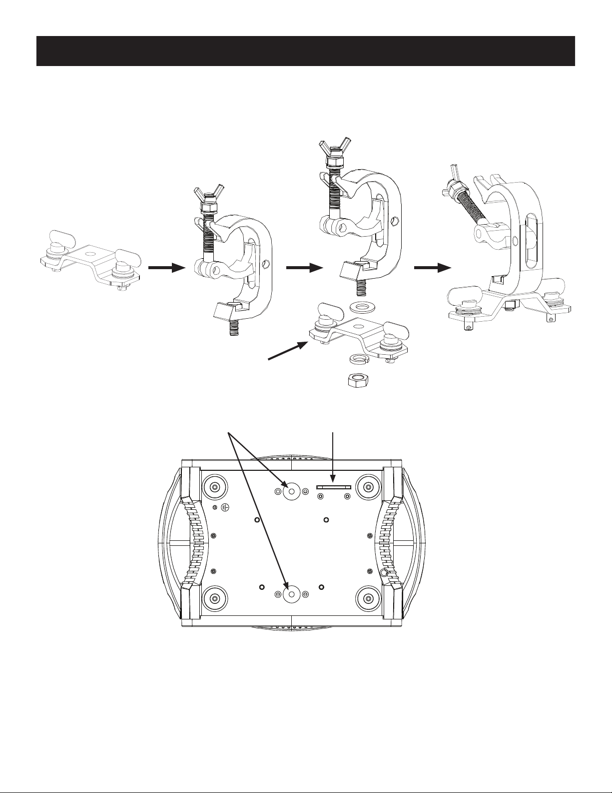
CLAMP
(Not Included)
OMEGA
BRACKET
OMEGA BRACKET
ATTACHMENT POINTS
SAFETY CABLE
ATTACHMENT POINTS
Screw one clamp via a M12 screw and nut into the Omega bracket. Insert the quick-lock fasteners of the
Omega bracket into the respective holes on the bottom of the Focus Spot 5Z. Tighten the quick-lock
fasteners fully clockwise. Pull the safety cable through the opening located on the base plate and
over the trussing system or a safe xation spot. Insert the end in the carabine and tighten the safety
screw.
ADJ Products, LLC - www.adj.com - Focus Spot 5Z User Manual Page 8
Page 10
Focus Spot 5Z Installation
When installing the unit, the trussing or area of installation must be able to hold 10 times the weight
without any deformation. When installing the unit must be secured with a secondary safety attachment,
e.g. and appropriate safety cable. Never stand directly below the unit when mounting, removing, or
servicing the unit.
Overhead mounting requires extensive experience, including calculating working load limits, installation
material being used, and perodic safety inspection of all installation material and unit. If you lack
these qualications, do not attempt the installation yourself.
These installaiton should be checked by a skilled person once a year.
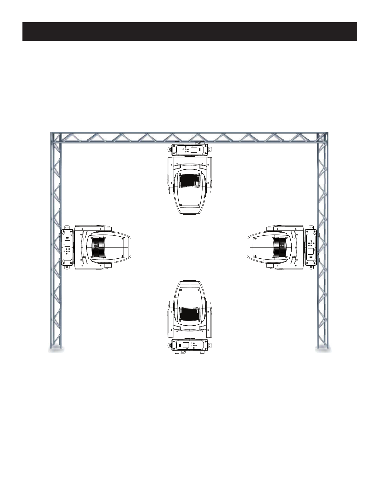
The Focus Spot 5Z is fully operational in three dierent mounting positions, hanging upside-down
from a ceiling or trussing, sideways on trussing, or set on a at level surface. Be sure this xture is
kept at least 12m (40ft) away from any ammable materials (decoration etc.). Always use and install
a safety cable as a safety measure to prevent accidental damage and/or injury in the event the
clamp fails (see previous page). Never use the carrying handles for secondary attachment.
ADJ Products, LLC - www.adj.com - Focus Spot 5Z User Manual Page 9
Page 11

Focus Spot 5Z Overview
1. Service Port
2. LED Display
3. Mode Button
Up Button
Down Button
Left Button
Right Button
Enter Button
4. Locking Power Connector In
5. Fuse Holder
6. Locking 5-Pin XLR Connector Out
7. Locking 5-Pin XLR Connector In
8. Locking Power Connector Out
1
32
4 5 6 7 8
ADJ Products, LLC - www.adj.com - Focus Spot 5Z User Manual Page 10
Page 12
Focus Spot 5Z DMX Set Up
REMOTE
CONTROL
INPUT
POWER
INPUT OUTPUT
SOUND
REMOTE
CONTROL
INPUT
POWER
INPUT OUTPUT
SOUND
REMOTE
CONTROL
INPUT
POWER
INPUT OUTPUT
DMX512
DMX+,DMX-,COMMON
1
2
3
Termination reduces signal errors and
avoids signal transmission problems
and interference. It is always advisable
to connect a DMX terminal, (Resistance
120 Ohm 1/4 W) between PIN 2 (DMX-)
and PIN 3 (DMX +) of the last fixture.
DMX-512: DMX is short for Digital Multiplex. This is a universal protocol used as a form of commu-
nication between intelligent fixtures and controllers. A DMX controller sends DMX data instructions
from the controller to the fixture. DMX data is sent as serial data that travels from fixture to fixture
via the DATA “IN” and DATA “OUT” XLR terminals located on all DMX fixtures (most controllers only
have a DATA “OUT” terminal).
DMX Linking: DMX is a language allowing all makes and models of dierent manufactures to be
linked together and operate from a single controller, as long as all xtures and the controller are DMX
compliant. To ensure proper DMX data transmission, when using several DMX fixtures try to use
the shortest cable path possible. The order in which fixtures are connected in a DMX line does not
influence the DMX addressing. For example; a fixture assigned a DMX address of 1 may be placed
anywhere in a DMX line, at the beginning, at the end, or anywhere in the middle. When a fixture is
assigned a DMX address of 1, the DMX controller knows to send DATA assigned to address 1 to that
unit, no matter where it is located in the DMX chain.
Data Cable (DMX Cable) Requirements (For DMX Operation): The Focus Spot 5Z can be controlled
via DMX-512 protocol. The DMX address is set on the front panel of the Focus Spot 5Z. Your unit and your
DMX controller require a 5-pin XLR connector for data input and data output. We recommend Accu-Cable
DMX cables. If you are making your own cables, be sure to use standard 110-120 Ohm shielded cable
(This cable may be purchased at almost all pro lighting stores). Your cables should be made with a male
and female XLR connector on either end of the cable. Also remember that DMX cable must be daisy
chained and cannot be split.
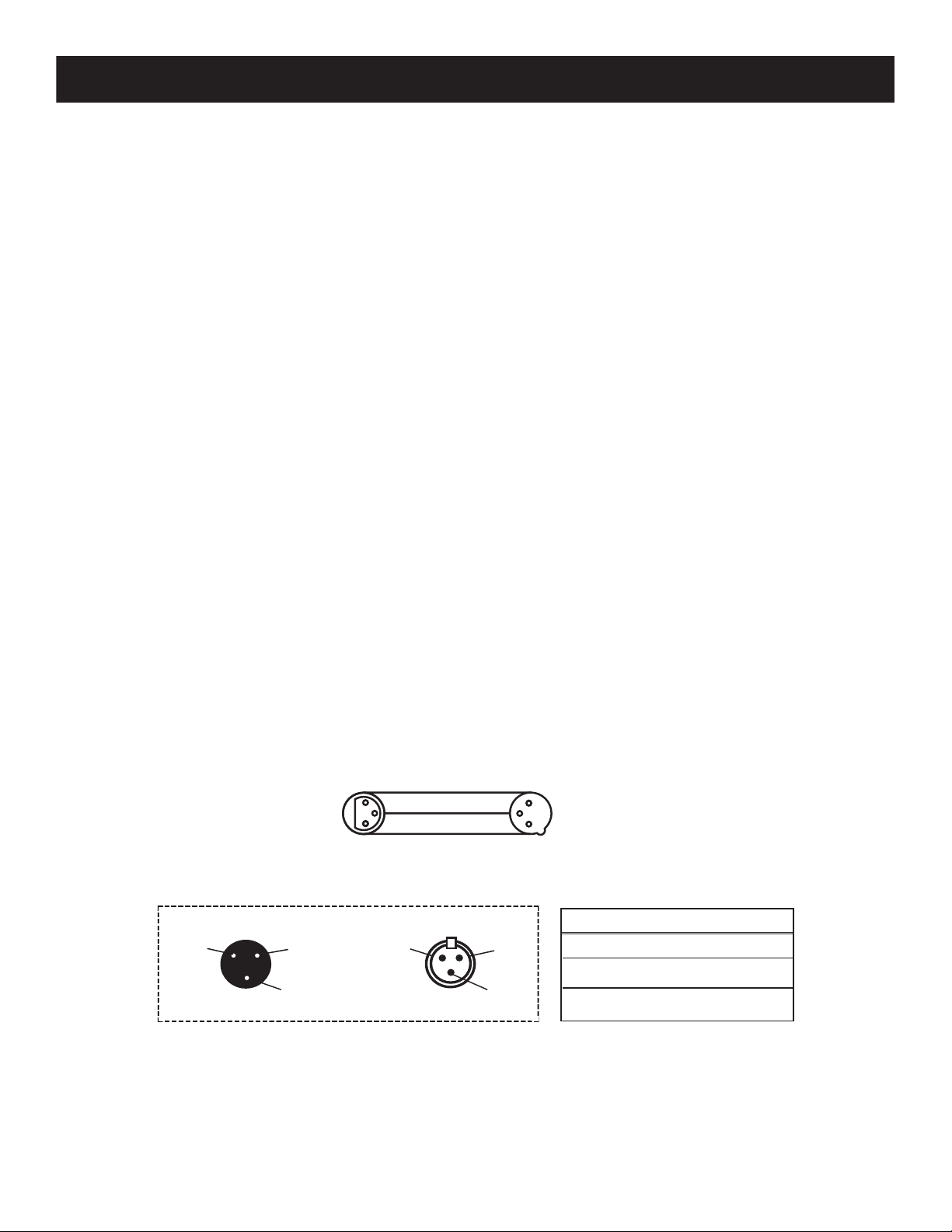
Notice: Be sure to follow gures one (1) and two (2) when making your own cables. Do not use the
ground lug on the XLR connector. Do not connect the cable’s shield conductor to the ground lug or
allow the shield conductor to come in contact with the XLR’s outer casing. Grounding the shield could
cause a short circuit and erratic behavior.
COMMON
XLR Male Socket
1 Ground
Figure 2
DMX512 OUT
3-PIN XLR
2 Cold
3 Hot
1
3
2
XLR Female Socket
2 Cold
DMX +
DMX -
1 Ground
3 Hot
1
3
2
DMX512 IN
3-PIN XLR
Figure 1
XLR Pin Conguration
Pin 1 = Ground
Pin 2 = Data Compliment (negative)
Pin 3 = Data True (positive)
ADJ Products, LLC - www.adj.com - Focus Spot 5Z User Manual Page 11
Page 13
Focus Spot 5Z DMX Set Up
POWER
SOUND
REMOTE
CONTROL
INPUT
POWER
INPUT OUTPUT
and PIN 3 (DMX +) of the last fixture.
Special Note: Line Termination.
When longer runs of cable are used, you may need to use a terminator
on the last unit to avoid erratic behavior. A terminator is a 110-120 ohm 1/4 watt resistor which is connected
between pins 2 and 3 of a male XLR connector (DATA + and DATA -). This unit is inserted in the female
XLR connector of the last unit in your daisy chain to terminate the line. Using a cable terminator (ADJ
part number Z-DMX/T) will decrease the possibilities of erratic behavior.
Termination reduces signal errors and
1
3
avoids signal transmission problems
and interference. It is always advisable
2
to connect a DMX terminal, (Resistance
120 Ohm 1/4 W) between PIN 2 (DMX-)
Figure 3
5-Pin XLR DMX Connectors.
Some manufactures use 5-pin DMX-512 data cables for DATA transmission in
place of 3-pin. 5-pin DMX xtures may be implemented in a 3-pin DMX line. When inserting standard
5-pin data cables in to a 3-pin line a cable adaptor must be used, these adaptors are readily available
at most electric stores. The chart below details a proper cable conversion.
3-Pin XLR to 5-Pin XLR Conversion
Conductor 5-Pin XLR Male (In)3-Pin XLR Female (Out)
Ground/Shield
Data Compliment (- signal)
Data True (+ signal)
Not Used
Not Used
Pin 1
Pin 2
Pin 3
Pin 1
Pin 2
Pin 3
Do Not Use
Do Not Use
ADJ Products, LLC - www.adj.com - Focus Spot 5Z User Manual Page 12
Page 14

Focus Spot 5Z DMX Addressing
All xtures should be given a DMX starting address when using a DMX controller, so the correct xture
responds to the correct control signal. This digital starting address is the channel number from which
the xture starts to “listen” to the digital control signal sent out from the DMX controller. The assignment
of this starting DMX address is achieved by setting the correct DMX address on the digital control
display on the xture.
You can set the same starting address for all xtures or a group of xtures, or set dierent addresses
for each individual xture. Setting all xtures to the same DMX address will cause all xtures to react
in the same way, in other words, changing the settings of one channel will aect all the xtures
simultaneously.
If you set each xture to a dierent DMX address, each unit will start to “listen” to the channel number
you have set, based on the quantity of DMX channels of each xture. That means changing the settings
of one channel will only aect the selected xture.
In the case of the Focus Spot 5Z, when in 19 channel mode you should set the starting DMX address
of the rst unit to 1, the second unit to 20 (19 + 1), the third unit to 39 (20 + 19), and so on. (See the
chart below for more details.)
Channel Mode
19 Channels 1 20 39 58
22 Channels 1 23 45 64
26 Channels 1 27 53 79
Unit 1
Address
Unit 2
Address
Unit 3
Address
Unit 4
Address
ADJ Products, LLC - www.adj.com - Focus Spot 5Z User Manual Page 13
Page 15

Focus Spot 5Z DMX Modes & Values
ADJ FOCUS SPOT 5Z
DMX Channel Values & Functions
Basic (19)
1
Supports Software Version > 1.0.3
*Rotation direction (Clockwise/Counter-Clockwise) and control of effects depends on head orientation and Pan/Tilt settings*
Standard (22) Extend (26) Values
1 1
Feature subject to change without notice
000-255
PAN MOVEMENT (8-BIT)
Pan Movement
Functions
2
2
3
3 3
4
5 5
6 64
2
4
000-255
000-255
000-255
000-007
008-014
015-021
022-028
029-035
036-042
043-049
050-056
057-063
064-127
128-189
190-193
194-255
000-007
008-014
015-021
022-028
029-035
036-042
043-049
050-056
057-063
064-127
128-189
190-193
194-255
PAN FINE (16-BIT)
Fine Control of Pan Movement
TILT MOVEMENT (8-BIT)
Tilt Movement
TILT FINE (16-BIT)
Fine Control of Tilt Movement
COLOR WHEEL 1
Open / White
Red
Orange
Yellow
Green
Dark Blue
Purple
Light Blue
Magenta
Color Indexing
Clockwise Rotation Fast - Slow
No Rotation
Counter-Clockwise Rotation Slow - Fast
COLOR WHEEL 2
Open / White
Lavender
Blue
CTB 5600
Green
Yellow
UV
CTO 3200
Pink
Color Indexing
Clockwise Rotation Fast - Slow
Stop
Counter-Clockwise Rotation Slow - Fast
ADJ Products, LLC - www.adj.com - Focus Spot 5Z User Manual Page 14
Page 16

Focus Spot 5Z DMX Modes & Values
Functions
Standard (22) Extend (26) ValuesBasic (19)
GOBO WHEEL
000-004
Open
005-019
020-034
Gobo 1
Gobo 2
035-049
050-064
5
7 7
065-079
080-094
095-109
110-124
125-139
140-154
155-169
170-189
190-221
222-223
224-255
Gobo 3
Gobo 4
Gobo 5
Gobo 6
Gobo 1 Shake (Slow-Fast)
Gobo 2 Shake (Slow-Fast)
Gobo 3 Shake (Slow-Fast)
Gobo 4 Shake (Slow-Fast)
Gobo 5 Shake (Slow-Fast)
Gobo 6 Shake (Slow-Fast)
Clockwise Rotation Fast-Slow
No Rotation
Counter-Clockwise Rotation Slow-Fast
GOBO ROTATION
000-127
8 86
9
10 108
97
11
128-189
190-193
194-255
000-031
032-063
064-095
096-127
128-159
160-191
192-223
224-255
000-255
000-255
Indexing
Clockwise Rotation (Fast-Slow)
No Rotation
Counter-Clockwise Rotation Slow-Fast)
SHUTTER & STROBE
Shutter Closed
Shutter Open
Strobe Slow-Fast
Shutter Open
Pulse Effect Slow-Fast
Shutter Open
Random Strobe Slow-Fast
Shutter Open
MASTER DIMMER
0%-100%
DIMMER FINE (16-BIT)
0%-100%
ADJ Products, LLC - www.adj.com - Focus Spot 5Z User Manual Page 15
Page 17

Focus Spot 5Z DMX Modes & Values
Functions
Standard (22) Extend (26) ValuesBasic (19)
PRISM 1 (6 FACET CIRCULAR)
11
11
12
13 15
14 1612
129
1310
14
17
000-031
032-255
000-127
128-189
190-193
194-255
000-031
032-255
000-127
128-189
190-193
194-255
Open
Shutter Open
PRISM 1 INDEXING & ROTATION
Indexing
Clockwise Rotation Fast-Slow
No Rotation
Counter-Clockwise Rotation Slow-Fast
PRISM 1 FINE INDEXING (16-BIT)000-255
PRISM 2 (5 FACET LINEAR)
Open
Shutter Open
PRISM 2 INDEXING & ROTATION
Indexing
Clockwise Rotation Fast-Slow
No Rotation
Counter-Clockwise Rotation Slow-Fast
PRISM 2 FINE INDEXING (16-BIT)000-255
15 1813
16 1914
1715
18 2216
21
000-255
000-255
000-255
000-255
FOCUS
Far-Near
ZOOM
Minimum-Maximum Beam
ZOOM FINE INDEXING (16-BIT)000-25520
FROST 1
0%-100%
FROST 2
0%-100%
ADJ Products, LLC - www.adj.com - Focus Spot 5Z User Manual Page 16
Page 18

Focus Spot 5Z DMX Modes & Values
Standard (22) Extend (26) ValuesBasic (19)
19 23
000-020
021-040
041-060
061-080
081-100
101-120
121
122
123
124
125
126
127
128
129
130
131
132
133
134
135
136
137
138
139
140
141-255
Functions
DIMMER MODES:
Standard
Stage
TV
Architectural
Theatre
Stage 2
DIMMING SPEED
0.1Sec.
0.2Sec.
0.3Sec.
0.4Sec.
0.5Sec.
0.6Sec.
0.7Sec.
0.8Sec.
0.9Sec.
1.0Sec.
1.5Sec.
2.0Sec.
3.0Sec.
4.0Sec.
5.0Sec.
6.0Sec.
7.0Sec.
8.0Sec.
9.0Sec.
10Sec.
Default to Unit Setting
DIMMER CURVES
20 24
21 2518
000-020
021-040
041-060
061-080
081-255
000-255
Linear
Square
Inverse Square
S-Curve
No Function
PAN/TILT SPEED
Fast-Slow
ADJ Products, LLC - www.adj.com - Focus Spot 5Z User Manual Page 17
Page 19

Focus Spot 5Z DMX Modes & Values
Functions
Standard (22) Extend (26) ValuesBasic (19)
LED REFRESH RATE & SPECIAL FUNCTIONS
000-010
011-078
11
12
13
14
15
16
17
18
19
20
21
22
23
24
25
26
27
28
29
30
22 2619
31
32
33
34
35
36
37
38
39
40
41
42
43
44
45
46
47
48
49
50
51
52
53
54
55
56
57
58
59
Default LED Refresh Rate 1200Hz
Refresh Rate (Hz)
900
910
920
930
940
950
960
970
980
990
1000
1010
1020
1030
1040
1050
1060
1070
1080
1090
1100
1110
1120
1130
1140
1150
1160
1170
1180
1190
1210
1220
1230
1240
1250
1260
1270
1280
1290
1300
1310
1320
1330
1340
1350
1360
1370
1380
1390
ADJ Products, LLC - www.adj.com - Focus Spot 5Z User Manual Page 18
Page 20

Focus Spot 5Z DMX Modes & Values
Standard (22) Extend (26) ValuesBasic (19)
LED REFRESH RATE & SPECIAL FUNCTIONS
60
61
62
63
64
65
66
67
68
69
70
71
72
73
74
75
76
77
22 2619
78
79
080-089
090-099
100-109
110-119
120-129
130-139
140-149
150-159
160-169
170-179
180-185
186-191
192-197
198-199
200-205
206-211
212-216
217-227
228-238
239-249
250-255
1400
1410
1420
1430
1440
1450
1460
1470
1480
1490
1500
2500
4000
5000
6000
10,000
15,000
20,000
25,000
Disable LED Refresh Rate
Enable Blackout with Pan/Tilt Movement
Disable Blackout with Pan/Tilt Movement
Enable Blackout with Color Change
Disable Blackout with Color Change
Enable Blackout with Gobo Change
Disable Blackout with Gobo Change
Reset All
Reset Pan/Tilt
Reset Color & Gobo
Reset Effect & Focus
Internal Program 1 (Scenes 1-8)
Internal Program 2 (Scenes 9-16)
Internal Program 3 (Scenes 17-24)
Internal Program 4 (Scenes 25-32)
Internal Program 5 (Scenes 33-40)
Internal Program 6 (Scenes 41-48)
Internal Program 7 (Scenes 49-56)
Fan Mode Low
Fan Mode High
Fan Mode Auto
No Function
Functions
ADJ Products, LLC - www.adj.com - Focus Spot 5Z User Manual Page 19
Page 21

Focus Spot 5Z System Menu
SYSTEM MENU
The xture includes an easy to navigate system menu control panel display where all necessary
settings and adjustments are made. During normal operation, pressing the MODE button once will
access the xture’s main menu. Once in the main menu, you can navigate through the dierent functions
with the UP and DOWN buttons. When you reach a eld that requires adjusting, press the ENTER
button to access that eld and use the LEFT and RIGHT buttons to adjust the eld. Pressing the
ENTER button once more will conrm your setting. You may exit the main menu at any time without
making any adjustments by pressing the MODE button.
System Menu Access: To access the system menu when the xture is not powered using the
internal battery, press and hold the MODE button to illuminate the LCD screen until the DMX
address is displayed. Then navigate to the desired system menu.
LCD CONTROL PANEL LOCKOUT
When the Key Lock function is activated, the control panel will automatically lock after the time set
under the Display submenu “Screen Saver Delay”.
When the Key Lock function is set to ON, the control panel will lock. Press and hold the MODE button
for 3 seconds to unlock.
When the Key Lock function is set to ON1, the control panel will lock, and will not unlock without a code.
To unlock the display follow these steps:
1. Press the UP button, and the display will change to: (one * appears).
2. Press the DOWN button, and the display will change to: (two * appear).
3. Press the UP button, and the display will change to: (three * appear).
4. Press the DOWN button, and the display will change to: (four * appear).
5. Press the ENTER buttton, and the display will be unlocked.
If the button sequence was entered correctly, the display and control panel will unlock. If the button
sequence was entered incorrectly, the display will return to the DMX addess display.
ADJ Products, LLC - www.adj.com - Focus Spot 5Z User Manual Page 20
*
* *
* * *
* * * *
Page 22

Focus Spot 5Z System Menu
MENU OPTIONS DESCRIPTIONSUBMENU
DMX SETTINGS
Set Address
DMX Channel Mode
No DMX Status Hold Last / Blackout / Manual
Primary
Secondary
001-XXX
Basic (19) / Standard (22) / Extended (26)
ON / OFF
ON / OFF
Pan Degree: 630 / 540
Pan Invert: ON / OFF
DMX Addressing
DMX Channel Mode Selection
DMX Lost Status
Primary Setting
Secondary Setting
Pan Degree Selection
Reverse Pan Motion
PERSONALITY
Status Settings
Fan Settings
Dim Modes
LED Refresh Rate
Dim Curve
Reset Motors
Display
Tilt Invert: ON / OFF
P./T. Feedback: ON / OFF
P./T. Speed: Speed 1 / Speed 2
Hibernation: Off / 01M~99M / 15M
Head Fan: Auto / High / Silent (Low)
Standard/Stage/TV/Architectur/Theatre/Stage2
Dim Speed: 0.1-10s
1200 / 900-1500 / 2500 / 4000 / 5000 / 6000
10000 / 15000 / 20000 / 25000 (Hz)
Linear / Square / Inverse Square / S-Curve
Reset All Motors: YES / NO
Pan/Tilt Reset: YES / NO
Color/Gobo Reset: YES / NO
Effect/Focus Reset: YES / NO
Intensity: 1~10 (Dimmest-Brightest)
Display Invert: YES / NO
Screen Saver Delay: OFF~10M
Reverse Tilt Motion
Pan/Tilt Movement Feedback
Pan/Tilt Movement Speed
Sleep Setting (No Activity)
Fan Speed Setting
Dimming Modes
Dimming Speed
LED Refresh Setting
Dimming Curves
Reset All Motors
Reset Pan/Tilt Motors
Reset Color/Gobo Motors
Reset Effect/Focus Motors
Display Intensity Adjustment
Display Inversion
Display Shutoff Time
Key Lock: OFF / ON / ON1 Display Control Lock
Service
Pass Code = 050
Effect Adjust (Calibration)
(Pass Code = 50)
USB Port Power: ON / OFF
Update Software: YES / NO
Factory Restore: YES / NO
(Pass Code = 11)
Calibration Adjustment
USB Port Activation
Software Update
Restore Factory Settings
ADJ Products, LLC - www.adj.com - Focus Spot 5Z User Manual Page 21
Page 23

Focus Spot 5Z System Menu
MENU OPTIONS DESCRIPTIONSUBMENU
MANUAL CONTROL
INTERNAL
PROGRAMS
Pan
Pan Fine
Tilt
Tilt Fine
Color 1
Color 2
Gobo
Gobo Rot
Shutter
Dimmer
Dimmer Fine
Prism 1
Prism 1 Rot.
Prism1Rot Fine
Prism 2
Prism 2 Rot.
Prism2Rot Fine
Focus
Zoom
Zoom Fine
Frost 1
Frost 2
Dim Modes
Dim Curves
P/T Speed
Special Function
Program 1
Program 2
Program 3
Program 4
Program 5
Program 6
Program 7
000-255
000-255
000-255
000-255
000-255
000-255
000-255
000-255
000-255
000-255
000-255
000-255
000-255
000-255
000-255
000-255
000-255
000-255
000-255
000-255
000-255
000-255
000-255
000-255
000-255
000-255
Speed: 000~255 Fade: 000~255
Speed: 000~255 Fade: 000~255
Speed: 000~255 Fade: 000~255
Speed: 000~255 Fade: 000~255
Speed: 000~255 Fade: 000~255
Speed: 000~255 Fade: 000~255
Speed: 000~255 Fade: 000~255
Manual Control Settings
Program 1 with Adjustments
Program 2 with Adjustments
Program 3 with Adjustments
Program 4 with Adjustments
Program 5 with Adjustments
Program 6 with Adjustments
Program 7 with Adjustments
ADJ Products, LLC - www.adj.com - Focus Spot 5Z User Manual Page 22
Page 24

Focus Spot 5Z System Menu
MENU OPTIONS DESCRIPTIONSUBMENU
Total Running Time
(Not Resettable)
Total Running Time
(Resettable)
Fixture Life Time
Power On Time: XXXXXX Hours
P-On Time-R: XXXXXX Hours
Total LED Time
P-On Time-Reset: YES / NO
Pass Code = 50
LED On Time: XXXXXX Hours
LED On Time-R: XXXXXX Hours
LED Hours Reset: YES / NO
Pass Code = 50
Current: XXX ˚F / XXX ˚C
Reset Total Running Time
Total LED On Running
Time (Not Resettable)
LED On Running Time
(Resettable)
Reset LED Running Time
Current Head Temperature
Maximum Temperature
INFORMATION
LED’s
Fixture Temps
Max Resettable: XXX ˚F / XXX ˚C
Max Not Resettable: XXX ˚F / XXX ˚C
Reset Lamp Temp: YES / NO
(Pass Code = 050)
Fan Info. (RPM)
DMX Values
Error Logs
Software Version VX.X Current Software Version
Notes:
(1) Current Maximum Temperature - Maximum fixture temp. that has been recorded, before reset and after reset.
(2) Maximum Temperature - Overall maximum fixture temp. that has been recorded. (Not Resettable)
(3) DMX Value options depend on the current DMX Channel mode setting.
LED Fan1: XXXX RPM LED Fan 1 Speed
LED Fan2: XXXX RPM LED Fan 2 Speed
Pan / Pan Fine / Tilt / Tilt Fine / Color 1 /
Color 2 / Gobo / Gobo Rot / Shutter / Dimmer /
Dimmer Fine / Prism 1 / Prism 1 Rot /
Prism1Rot Fine / Prism 2 / Prism 2 Rot/
Prism2Rot Fine / Focus / Zoom / Zoom Fine /
Frost 1 / Frost 2 / Dim Modes / Dim Curves /
P/T Speed / SpecialFunction
Fixture Errors
Reset Error Log - Pass Code = 50
Reached (Resettable)
(See Note 1)
Maximum Temperature
Reached (Not Resettable)
(See Note 2)
Reset LED Temperature
(Max Resettable)
Current DMX Values
(See Note 3)
List of Errors (One by One)
Clear the Error Log
(3)
(1)
(2)
ADJ Products, LLC - www.adj.com - Focus Spot 5Z User Manual Page 23
Page 25

Focus Spot 5Z System Menu
DMX SETTINGS - The submenus listed under DMX SETTINGS are as follows: Set Address, DMX
Channel Mode, and No DMX Status.
- SET ADDRESS - In this submenu you can nd and set your desired DMX address.
- DMX CHANNEL MODE - In this submenu you can nd and set your desired DMX channel mode.
- NO DMX STATUS - This submenu setting is used as a precaution mode in case the DMX signal
or power is lost or interrupted. The operating mode chosen in this submenu is the running mode
the xture will go into when the DMX signal is lost. Listed below are the 3 modes.
• Hold Last - This setting will have the xture stay in the last DMX setup.
• Blackout - This setting will have the xture automatically go into stand by/blackout mode.
• Manual - This setting will go into the current manual control set up. See MANUAL CONTROL.
PERSONALITY - The submenus listed under PERSONALITY are as follows: Primary & Secondary
Settings, Status Settings, Fan Settings, Di
Motors, Display, and Service.
- PRIMARY & SECONDARY SETTINGS - In this submenu you are able to designate the units as
either “Primary” or “Secondary” unit in a primary-secondary set up.
m Modes, LED Refresh Rate, Dimf Curves, Reset
- STATUS SETTINGS - In this submenu you are able to access and adjust/change: Pan Degree,
Pan Invert, Tilt Invert, P./T. Feedback, P./T. Speed, and Hibernation.
- FAN SETTINGS - In this submenu you are able to select your desired fan speed setting.
- DIM MODES - In this submenu you are able to select your desired dimmer mode and adjust the
dimming speed time. See the dimmer mode chart on page 26 for more information.
- LED REFRESH RA
- DIM CURVE - In this submenu you are able to select your desired dimmer curve. See the dimmer
curve chart on page 26 for more information.
- RESET MOTORS - In this submenu you are able to reset selected motors.
- DISPLAY - In this submenu you you are able to adjust the display intensity, invert the display, set the
display lock time, and activate/deactivate the display lock.
- SERVICE - In this submenu you are able to access and adjust/change: calibration (effect adjust),
activate/deactivate the USB port power, update the software, and restore the factory settings.
TE - In this submenu you are able to select your desired LED refresh rate.
MANUAL CONTROL - This menu is for manual testing and manual control.
INTERNAL PROGRAMS - In this menu you are able to select 1 of 7 internal programs to run. Program
running speed and fade speed are adjustable.
ADJ Products, LLC - www.adj.com - Focus Spot 5Z User Manual Page 24
Page 26

Focus Spot 5Z System Menu
INFORMATION - The submenus listed under INFORMATION are as follows: Fixture Life Time,
Total LED Time, Fixture Temps, Fan Info. (RPM), DMX Values, Error Logs, and Software Version.
- FIXTURE LIFE TIME
• Power On Time -The TOTAL power ON running time of the unit is displayed. This time CANNOT
be reset.
• P-On Time-R - The CURRENT power ON running time of the unit is displayed. This running time
may not be the same as the TOTAL power ON running time displayed under “Power On Time”.
This time CAN be reset. NOTE: The displayed time represents the current power ON time
since the last reset.
• P-On Time-Reset - With this function you can reset the CURRENT power ON running time that is
displayed under “P-On Time-R”.
- TOTAL LED TIME
• LED On Time - The TOTAL LED ON time is displayed. This total LED ON time CANNOT be reset.
• LED On Time-R - The CURRENT LED ON running time is displayed. This running time may not
be the same as the TOTAL LED ON time displayed under “LED On Time”. This current LED ON
time CAN be reset. NOTE: The displayed time represents the current LED ON time since the
last reset.
• LED Hours Reset - With this function you can reset the CURRENT LED ON time that is displayed
under “LED On Time-R”.
- FIXTURE TEMPS
• LED’s:
• Current - The current LED temperature will be displayed.
• Max Resettable - The current highest temperature the LED has reached will be displayed.
This LED temperature may not be the same as the temperature displayed under “CURRENT” or
“MAX NOT RESETTABLE”. This LED temperature CAN be reset.
NOTE: The displayed temperature represents the highest temperature the LED has
reached since the last reset.
• Max Not Resettable - The highest temperature the LED has reached will be displayed. This
LED temperature CANNOT be reset, and could continue rise.
• RESET LED TEMP - With this function you can reset the “MAX RESETTABLE” LED temperature.
NOTE: When the temperature is reset, the temperature will revert to the CURRENT LED temperature.
- FAN INFO. (RPM) - In this submenu the current fan speed’s will be displayed.
- DMX VALUES - Displays the DMX values of any DMX channel that is currently in use.
NOTE: DMX value options depend on the current DMX channel mode setting.
- ERROR LOGS - In this submenu you are able to check any unit errors as well a clear the error log.
- SOFTWARE VERSION - Current software version is displayed.
ADJ Products, LLC - www.adj.com - Focus Spot 5Z User Manual Page 25
Page 27

Focus Spot 5Z Dimmer Mode Chart
DIMMER
100%
50%
10%
0%
Time (ms)
255 255
0 0
Stage 780 1100 1540 1660
TV 1180 1520 1860 1940
Architectural 1380 1730 2040 2120
0 sec Fade Time
1 sec Fade Time
Rise Time Down Time
0 Sec
Dimming Curve
Ramp Effect
Rise Time (ms) Down Time (ms) Rise Time (ms) Down Time (ms)
Standard (default) 0 0 0 0
Theatre 1580 1940 2230 2280
Stage 2
0 1100 0 1660
Focus Spot 5Z Dimmer Curve Chart
100%
Output
100%
Output
100%
Output
100%
Output
0
DMX % DMX % DMX % DMX %
0
0
LINEAR SQUARE INVERSE SQUARE S-CURVE
ADJ Products, LLC - www.adj.com - Focus Spot 5Z User Manual Page 26
0
Page 28

Focus Spot 5Z Gobo Replacement
The gobo’s featured in this unit are interchangable. Remember when changing these gobo’s that
they are thin and easy to bend.
If your removing/replacing the glass gobo, please be very careful. REMEMBER, this is a glass gobo,
it is delicate. Please be very careful when removing/replacing any of the gobo’s.
Caution! Never open the unit when in use. Always disconnect the main power before attempting to
change the gobos.
Locating the Gobo wheel: After disconnecting the main power, position the head with the lens
facing forward. When looking through the front lens, position the head so that the frost lters are
located at the top (see image below). When the frost lters are located at the top, the shell that
needs to be uscrewed and removed is now facing up.
FROST FILTER FROST FILTER
1. To change a gobo, uscrew the 4 screws that secure the shell to the unit. Gently lift and remove the
shell.
2. Once the shell is removed, you will be able to access the gobo wheel. Turn the wheel until you
come across the gobo you would like to change.
3. Once you have found the gobo you would like to change, use your finger to carefully turn the
small inner gear so that the “alignment dot” on the inner gear, lines up with the gobo you would
like to replace (Figure 1).
4. Once the gobo and “alignment dot” are lined up, CAREFULLY, from underneath the gobo wheel,
push the gobo housing with gobo up and pull the housing out.
CAUTION! Do not put to much pressure on the gobo itself due to the fact it is thin and it can bend.
5. Using your fingernail or needle nose pliers, CAREFULLY remove the retainer ring that secures the
gobo in place. After the retainer ring is removed, your are able to remove the gobo (Figure 2).
6. Change the gobo and replace the retainer ring.
NOTE: The black side of the gobo faces outwards in the gobo holder.
7. To reinsert the gobo housing back into the gobo wheel, make sure the “alignment dot” lines up
with the “protruding pin” (Figure 3). The “protruding pin” secures the gobo housing to the gobo
wheel. You will feel the gobo housing “lock” into place when the housing is inserted correctly.
8. Reassemble the unit.
ADJ Products, LLC - www.adj.com - Focus Spot 5Z User Manual Page 27
Page 29

Focus Spot 5Z Gobo Replacement
(FIGURE 1)
(FIGURE 2)
INNER GEAR
“ALIGNMENT DOT”
INNER GEAR
“ALIGNMENT DOT”
INNER GEAR
INNER GEAR
“ALIGNMENT DOT”
PROTRUDING PIN
(FIGURE 3)
PROTRUDING PIN
Focus Spot 5Z Gobos
GOBO 1 GOBO 5GOBO 3 GOBO 4GOBO 2 GOBO 6
ADJ Products, LLC - www.adj.com - Focus Spot 5Z User Manual Page 28
Page 30

Focus Spot 5Z Dimensional Drawing
*NOT TO SCALE
182.37mm / 7.18”
463.45mm / 18.25”
333.75mm / 13.14”
230.36mm / 9.07”
107mm
4.21”
174mm / 6.85”
278.61mm / 10.97”
93.7mm / 3.69”
174mm / 6.85”
75.15mm / 2.96”
ADJ Products, LLC - www.adj.com - Focus Spot 5Z User Manual Page 29
Page 31

Focus Spot 5Z Fuse Replacement
Unplug the unit from any power source it may be connected to. Once the power has been disconnected,
use a flat head screw driver to unscrew the fuse holder located next to the power input. Remove the
bad fuse and replace with a new one, and screw the fuse holder back in.
Focus Spot 5Z Multiple Unit Power Linking
With this feature you can connect the xtures to one another using the power cable input and
output sockets.
NOTE: USE CAUTION WHEN POWER LINKING OTHER FIXTURES AS THE POWER
CONSUMPTION OF OTHER MODEL FIXTURES MAY EXCEED THE MAX POWER OUTPUT ON
THIS FIXTURE! CHECK SILK SCREEN FOR MAX AMPS.
Focus Spot 5Z Trouble Shooting
Listed below are a few common problems the user may encounter, with solutions.
Unit not responding to DMX:
1. Check that the DMX cables are connected properly and are wired correctly (pin 3 is “hot”; on
some other DMX devices pin 2 may be ‘hot’). Also, check that all cables are connected to the right
connectors; it does matter which way the inputs and outputs are connected.
Focus Spot 5Z Cleaning
Due to fog residue, smoke, and dust cleaning the internal and external optical lenses must be carried out periodically to optimize light output.
1. Use normal glass cleaner and a soft cloth to wipe down the outside casing.
2. Clean the external optics with glass cleaner and a soft cloth every 20 days.
3. Always be sure to dry all parts completely before plugging the unit back in.
Cleaning frequency depends on the environment in which the fixture operates (i.e. smoke, fog residue, dust, dew).
ADJ Products, LLC - www.adj.com - Focus Spot 5Z User Manual Page 30
Page 32

Focus Spot 5Z Limited Warranty (USA Only)
MANUFACTURER’S LIMITED WARRANTY
A. ADJ Products, LLC hereby warrants, to the original purchaser, ADJ Products, LLC products to be free of manufacturing
defects in material and workmanship for a prescribed period from the date of purchase (see specific warranty period
on reverse). This warranty shall be valid only if the product is purchased within the United States of America, including
possessions and territories. It is the owner’s responsibility to establish the date and place of purchase by acceptable
evidence, at the time service is sought.
B. For warranty service you must obtain a Return Authorization number (RA#) before sending back the product–please
contact ADJ Products, LLC Service Department at 800-322-6337. Send the product only to the ADJ Products, LLC
factory. All shipping charges must be pre-paid. If the requested repairs or service (including parts replacement) are
within the terms of this warranty, ADJ Products, LLC will pay return shipping charges only to a designated point
within the United States. If the entire instrument is sent, it must be shipped in it’s original package. No accessories
should be shipped with the product. If any accessories are shipped with the product, ADJ Products, LLC shall
have no liability whatsoever for loss of or damage to any such accessories, nor for the safe return thereof.
C. This warranty is void if the serial number has been altered or removed; if the product is modified in any manner
which ADJ Products, LLC concludes, after inspection, affects the reliability of the product; if the product has been
repaired or serviced by anyone other than the ADJ Products, LLC factory unless prior written authorization was issued
to purchaser by ADJ Products, LLC; if the product is damaged because not properly maintained as set forth in the
instruction manual.
D. This is not a service contract, and this warranty does not include maintnance, cleaning or periodic check up.
During the period specified above, ADJ Products, LLC will replace defective parts at its expense with new or
refurbished parts, and will absorb all expenses for warranty service and repair labor by reason of defects in material or
workmanship. The sole responsibility of ADJ Products, LLC under this warranty shall be limited to the repair of the
product, or replacement thereof, including parts, at the sole discretion of ADJ Products, LLC. All products covered
by this warranty were manufactured after August 15, 2012, and bear indentifying marks to that effect.
E. ADJ Products, LLC reserves the right to make changes in design and/or improvements upon its products without
any obligation to include these changes in any products theretofore manufactured.
No warranty, whether expressed or implied, is given or made with respect to any accessory supplied with products
described above. Except to the extent prohibited by applicable law, all implied warranties made by ADJ Products,
LLC in connection with this product, including warranties of merchantability or fitness, are limited in duration to the
warranty period set forth above. And no warranties, whether expressed or implied, including warranties of merchantability or
fitness, shall apply to this product after said period has expired. The consumer’s and/or Dealer’s sole remedy shall
be such repair or replacement as is expressly provided above; and under no circumstances shall ADJ Products,
LLC be liable for any loss or damage, direct or consequential, arising out of the use of, or inability to use, this
product.
This warranty is the only written warranty applicable to ADJ Products, LLC Products and supersedes all prior warranties
and written descriptions of warranty terms and conditions heretofore published.
MANUFACTURER’S LIMITED WARRANTY PERIODS:
• Non L.E.D. Lighting Products = 1-year (365 days) Limited Warranty (Such as: Special Effect Lighting, Intelligent
Lighting, UV lighting, Strobes, Fog Machines, Bubble Machines, Mirror Balls, Par Cans, Trussing, Lighting Stands
etc. excluding LED and lamps)
• Laser Products = 1 Year (365 Days) Limited Warranty (excluding laser diodes which have a 6 month limited
warranty)
• L.E.D. Products = 2-year (730 days) Limited Warranty (excluding batteries which have a 180 day limited warranty).
Note: 2 Year Warranty only applies to purchases within the United States.
• StarTec Series = 1 Year Limited Warranty (excluding batteries which have a 180 day limited warranty).
• ADJ DMX Controllers = 2 Year (730 Days) Limited Warranty
Page 33

Focus Spot 5Z Specifications
Model:
Voltage: 100V ~ 240V/50~60Hz
LEDs: 1 x 200W LED
Working Position: Any safe working position
Power Draw: 280W
Fuse: 3A
Dimensions: 7.15” (L) x 10.97” (W) x 18” (H)
181.5 x 278.61 x 457.4mm
Weight: 23lbs. / 10 kgs
Colors: Color Wheel 1:
8 Colors + White
Color Wheel 2:
8 Colors + White
Gobos: 6 Gobos (1 Glass) + Open
Aluminum Gobos:
Inner Diameter: 19mm
Outer Diameter: 23mm
Thickness: 0.5mm
Glass Gobo:
Inner Diameter: 19mm
Outer Diameter: 23mm
Thickness: 3.3mm
Focus Spot 5Z
DMX Channels: 3 DMX Modes: 19/22/26
Warranty: 2 Year (730 days)
Please Note: Specications and improvements in the design of
this unit and this manual are subject to change.
 Loading...