

Page 1
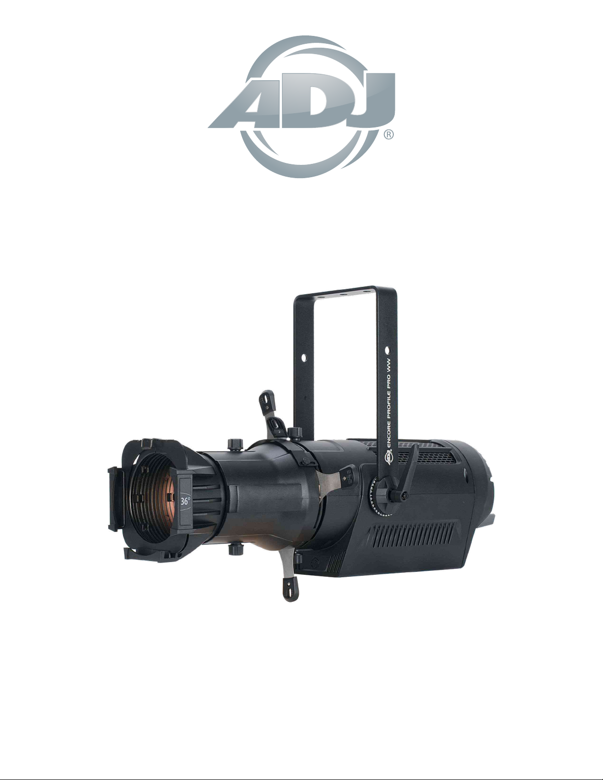
ENCORE PROFILE PRO WW
User Instructions
Shown with optional 36° Lens Kit. Lens Kits sold separately.
Page 2
©2020 ADJ PRODUCTS LLC all rights reserved. Information, specications, diagrams, images, and
instructions herein are subject to change without notice. ADJ logo and identifying product names and
numbers herein are trademarks of ADJ PRODUCTS LLC. Copyright protection claimed includes all
forms and matters of copyrightable materials and information now allowed by statutory or judicial law
or hereinafter granted. Product names used in this document may be trademarks or registered
trademarks of their respective companies and are hereby acknowledged. All non-ADJ brands and
product names are trademarks or registered trademarks of their respective companies.
ADJ PRODUCTS LLC and all afliated companies hereby disclaim any and all liabilities for property,
equipment, building, and electrical damages, injuries to any persons, and direct or indirect economic
loss associated with the use or reliance of any information contained within this document, and/or as a
result of the improper, unsafe, insufcient and negligent assembly, installation, rigging, and operation
of this product.
FCC STATEMENT
This device complies with Part 15 of the FCC Rules. Operation is subject to the following two
conditions: (1) this device may not cause harmful interference, and (2) this device must accept any
interference received, including interference that may cause undesired operation.
FCC RADIO FREQUENCY INTERFERENCE WARNINGS & INSTRUCTIONS
This product has been tested and found to comply with the limits as per Part 15 of the FCC Rules.
These limits are designed to provide reasonable protection against harmful interference in a residential
installation. This device uses and can radiate radio frequency energy and, if not installed and used in
accordance with the included instructions, may cause harmful interference to radio communications.
However, there is no guarantee that interference will not occur in a particular installation. If this device
does cause harmful interference to radio or television reception, which can be deter- mined by turning
the device off and on, the user is encouraged to try to correct the interference by one or more of the
following methods:
• Reorient or relocate the device.
• Increase the separation between the device and the receiver.
• Connect the device to an electrical outlet on a circuit different from which the radio receiver
is connected.
• Consult the dealer or an experienced radio/TV technician for help.
Energy Saving Matters (EuP 2009/125/EC)
Saving electric energy is a key to help protecting the environment. Please turn off all electrical products
when they are not in use. To avoid power consumption in idle mode, disconnect all electrical equipment
from power when not in use. Thank you!
D O C U M E N T V E R S I O N
Due to additional product features and/or enhancements, an updated version of
this document may be available online.
Please check www.adj.com for the latest revision/update of this manual, before
beginning installation and/or programming.
Date Document Version SoftwareVersion
07/23/2020 1.0 1.02 2/3/6 Initial Release
DMX Channel Modes Notes
≥
2
Page 3
Encore Prole Pro WW Table of Contents
General Information 4
Warranty (USA Only) 5
Warranty Registration | Features 6
Safety Guidelines 7
Overview 8
Lens & Gobo Holder Installation 9
Installation 10
System Menu 13
Multiple Unit Power Linking | Dimmer Mode Chart 16
DMX Setup 17
DMX Addressing 18
DMX Channel Functions & Values 19
Specications 22
Dimensional Drawings 23
Dimensional Drawings of Optional Lens Kits 24
Troubleshooting | Cleaning | Maintenance 27
3
Page 4

Encore Prole Pro WW Introduction
Unpacking: Thank you for purchasing the Encore Prole Pro WW by ADJ Products, LLC. Every
Encore Prole Pro WW has been thoroughly tested and has been shipped in perfect operating condition.
Carefully check the shipping carton for damage that may have occurred during shipping. If the carton
appears to be damaged, carefully inspect your xture for any damage and be sure all accessories
necessary to operate the unit has arrived intact. In the case damage has been found or parts are
missing, please contact our toll free customer support number for further instructions. Do not return this
unit to your dealer without rst contacting customer support.
Introduction: The ADJ Encore Prole Pro WW is a DMX intelligent, high powered LED xture. To optimize
the performance of this product, please read these operating instructions carefully to familiarize yourself
with the basic operations of this unit. These instructions contain important safety information regarding
the use and maintenance of this unit. Please keep this manual with the unit, for future reference.
Customer Support: Contact ADJ Service for any product related service and support needs. Also visit
https://forums.adj.com/ with questions, comments or suggestions.
Parts:To purchase parts online visit http://parts.americandj.com
ADJ SERVICEUSA-Monday-Friday 8:00am to 4:30pm PST
Voice: 800-322-6337 | Fax:323-582-2941 | support@adj.com
ADJ SERVICE EUROPE - Monday - Friday 08:30to17:00CET
Voice:+31455468560 | Fax:+31455468596 | support@adj.eu
ADJ PRODUCTS, LLC USA
6122 S. Eastern Ave. Los Angeles, CA. 90040
323-582-2650 | Fax 323-532-2941 | www.adj.com | info@adj.com
ADJ SUPPLY Europe B.V Junostraat 2 6468 EW Kerkrade, The Netherlands
+31 (0)45 546 85 00 | Fax +31 45 546 85 99 | www.adj.eu | info@adj.eu
ADJ PRODUCTS GROUP Mexico
AV Santa Ana 30 Parque Industrial Lerma, Lerma, Mexico 52000
+52 (728) 282-7070
Caution! There are no user serviceable parts inside this unit. Do not attempt any repairs yourself, doing
so will void your manufactures warranty. In the unlikely event your unit may require service please
contact ADJ Products, LLC.
PLEASE recycle the shipping carton whenever possible.
4
Page 5

Encore Prole Pro WW Limited Warranty (USA Only)
A. ADJ Products, LLC hereby warrants, to the original purchaser, ADJ Products, LLC products to be
free of manufacturing defects in material and workmanship for a prescribed period from the date of
purchase (see specic warranty period on reverse). This warranty shall be valid only if the product
is purchased within the United States of America, including possessions and territories. It is the
owner’s responsibility to establish the date and place of purchase by acceptable evidence, at the
time service is sought.
B. For warranty service, you must obtain a Return Authorization number (RA#) before sending the
product back—please contact ADJ Products, LLC Service Department at 800-322-6337. Send the
product only to the ADJ Products, LLC factory. All shipping charges must be prepaid. If the
requested repairs or service (including parts replacement) are within the terms of this warranty, ADJ
Products, LLC will pay return shipping charges only to a designated point within the United States.
If the entire instrument is sent, it must be shipped in its original package and packaging material. No
accessories should be shipped with the product. If any accessories are shipped with the product,
ADJ Products, LLC shall incur no liability whatsoever for loss of or damage to any such accessories,
nor for the safe return thereof.
C. This warranty is void if the product serial number and/or labels are altered or removed; if the product
is modied in any manner which ADJ Products, LLC concludes, after inspection, affects the
reliability of the product; if the product has been repaired or serviced by anyone other than the ADJ
Products, LLC factory unless prior written authorization was issued to purchaser by ADJ Products,
LLC; if the product is damaged because it was not properly maintained as set forth in the product
instructions, guidelines and/or user manual.
D. This is not a service contract, and this warranty does not include maintenance, cleaning, or periodic
checkup. During the period specied above, ADJ Products, LLC will replace defective parts at its
expense with new or refurbished parts, and will absorb all expenses for warranty service and repair
labor by reason of defects in material or workmanship. The sole responsibility of ADJ Products, LLC
under this warranty shall be limited to the repair of the product, or replacement thereof, including
parts, at the sole discretion of ADJ Products, LLC. All products covered by this warranty were
manufactured after August 15, 2012, and bear identifying marks to that effect.
E. ADJ Products, LLC reserves the right to make changes in design and/or improvements upon its
products without any obligation to include these changes in any products theretofore manufactured.
F. No warranty, whether expressed or implied, is given or made with respect to any accessory supplied
with products described above. Except to the extent prohibited by applicable law, all implied
warranties made by ADJ Products, LLC in connection with this product, including warranties of
merchantability or tness, are limited in duration to the warranty period set forth above. And all
warranties, whether expressed or implied, including warranties of merchantability or tness, are
limited in duration to the warranty period set forth above. The consumer’s and/or dealer’s sole
remedy shall be such repair or replacement as is expressly provided above; and under no
circumstances shall ADJ Product, LLC be liable for any loss and/or damage, direct and/or
consequential arising out of the use of, and/or inability to use this product.
G. This warranty is the only written warranty applicable to ADJ Products, LLC products, and
supersedes all prior warranties and written descriptions of warranty terms and conditions heretofore
published.
MANUFACTURER’S LIMITED WARRANTY PERIODS:
Non-LED Lighting Products = 1-Year (365 Days) (Including Special Effect Lighting, Intelligent Lighting, UV
lighting, Strobes, Fog Machines, Bubble Machines, Mirror Balls, Par Cans, Trussing, Lighting Stands, Power/Data
Distribution, etc. excluding LED and lamps)
Laser Products = 1-Year (365 Days) (excluding laser diodes which have a 6-Month Limited Warranty)
LED Products = 2-Year (730 Days) (excluding batteries which have a 180 Day Limited Warranty)
NOTE: 2-Year (730 Days) Limited Warranty ONLY applies to product purchased within the United States.
StarTec Series = 1-Year (365 Days) (excluding batteries which have a 180 Day Limited Warranty)
ADJ DMX Controllers = 2 Year (730 Days)
American Audio Products = 1 Year (365 Days)
5
Page 6

Encore Prole Pro WW Warranty Registration
The Encore Prole Pro WW carries a 2 year limited warranty. Please ll out the enclosed warranty card
to validate your purchase. All returned service items whether under warranty or not, must be freight prepaid and accompany a return authorization (R.A.) number. The R.A. number must be clearly written on
the outside of the return package. A brief description of the problem as well as the R.A. number must
also be written down on a piece of paper included in the shipping carton. If the unit is under warranty,
you must provide a copy of your proof of purchase invoice. You may obtain a R.A. number by contacting
our customer support team on our customer support number. All packages returned to the service
department not displaying a R.A. number on the outside of the package will be returned to the shipper.
Encore Prole Pro WW Features
The Encore Prole Pro WW™ ellipsoidal features a high powered 260W Warm White >97CRI 3,200K
LED engine producing 10,000+ total lumens, 5°, 10°, 14°, 19°, 26°, 36°, and 50° interchangeable lens
options (sold separately), (4) blade manual framing shutters, manual focus, supports B size metal HT
transparency gobos, DMX controlled electronic strobe, and variable dimming curves and dimming
modes, adjustable refresh frequency for icker free operation for TV and FILM, locking 5-pin XLR
In/Out and Locking Power In/Out, (4) button LCD control display panel, an integrated rigging yoke, quiet
fan cooling, and a multi-voltage universal auto switching power supply (AC100-240v).
6
Page 7

Encore Prole Pro WW Safety Precautions
THIS FIXTURE IS COMPOSED OF SOPHISTICATED ELECTRONIC COMPONENTS. TO
GUARANTEE SMOOTH OPERATION, IT IS IMPORTANT TO FOLLOW ALL INSTRUCTIONS AND
GUIDELINES IN THIS MANUAL. ADJ PRODUCTS, LLC IS NOT RESPONSIBLE FOR INJURY AND/
OR DAMAGES RESULTING FROM THE MISUSE OF THIS FIXTURE DUE TO THE DISREGARD OF
THE INFORMATION PRINTED IN THIS MANUAL. ONLY QUALIFIED AND/OR CERTIFIED
PERSONNEL SHOULD PERFORM INSTALLATION OF THIS FIXTURE AND ONLY THE ORIGINAL
RIGGING PARTS INCLUDED WITH THIS FIXTURE SHOULD BE USED FOR INSTALLATION. ANY
MODIFICATIONS TO THE FIXTURE AND/OR CERTIFIED PERSONNEL SHOULD PERFORM
INSTALLATION OF THIS FIXTURE AND/OR THE INCLUDED MOUNTING HARDWARE WILL VOID
THE ORIGINAL MANUFACTURER’S WARRANTY AND INCREASE THE RISK OF DAMAGE
AND/OR PERSONAL INJURY.
• PROTECTION CLASS 1 - FIXTURE MUST BE PROPERLY GROUNDED
• THERE ARE NO USER SERVICEABLE PARTS INSIDE THIS UNIT.
• DO NOT ATTEMPT ANY REPAIRS YOURSELF; DOING SO WILL VOID YOUR
MANUFACTURER’S WARRANTY. DAMAGES RESULTING FROM MODIFICATIONS TO THIS
FIXTURE AND/OR THE DISREGARD OF SAFETY INSTRUCTIONS AND GUIDELINES IN THIS
MANUAL VOID THE MANUFACTURE’S WARRANTY AND ARE NOT SUBJECT TO ANY
WARRANTY CLAIMS AND/OR REPAIRS.
• DO NOT PLUG FIXTURE INTO A DIMMER PACK!
• NEVER OPEN THIS FIXTURE WHILE IN USE!
• UNPLUG POWER BEFORE SERVICING FIXTURE!
• NEVER TOUCH FIXTURE DURING OPERATION, AS IT MAY BE HOT!
• KEEP FLAMMABLE MATERIALS AWAY FROM FIXTURE!
• NEVER LOOK DIRECTLY INTO THE LIGHT SOURCE!
• RETINA INJURY RISK - MAY INDUCE BLINDNESS!
• SENSITIVE PERSONS MAY SUFFER AN EPILEPTIC SHOCK!
• INDOOR / DRY LOCATIONS USE ONLY!
• DO NOT EXPOSE FIXTURE TO RAIN AND MOISTURE!
• MINIMUM DISTANCE TO OBJECTS/SURFACES
• MUST BE 6.6 FEET (2 METERS)
• MAXIMUM TEMP OF EXTERNAL SURFACE 185° F (85°C)
• MINIMUM DISTANCE OF INFLAMMABLE MATERIALS
• FROM THE SURFACE 1.6 FEET (0.5 METER)'
• DO NOT TOUCH the xture housing during operation. Turn OFF the power and allow approximately
60 minutes for the xture to cool down before serving.
• DO NOT shake xture, avoid brute force when installing and/or operating xture.
• DO NOT operate xture if the power cord is frayed, crimped, damaged and/or if any of the power
cord connectors are damaged and do not insert into the xture securely with ease. NEVER force a
power cord connector into the xture. If the power cord or any of its connectors are damaged,
replace it immediately with a new one of similar power rating.
• DO NOT block any air ventilation slots. All fan and air inlets must remain clean and never blocked.
Allow approx. 6” (15cm) between xture and other devices or a wall for proper cooling.
• When installing xture in a suspended environment, always use mounting hardware that is no less than
M10 x 25 mm, and always install xture with an appropriately rated safety cable.
• Always disconnect xture from main power source before performing any type of service and/or
cleaning procedure. Only handle the power cord by the plug end, never pull out the plug by tugging
the wire portion of the cord.
• During the initial operation of this xture, a light smoke or smell may emit from the interior of the
xture. This is a normal process and is caused by excess paint in the interior of the casing burning off
from the heat associated with the lamp and will decrease gradually over time.
• Consistent operational breaks will ensure xture will function properly for many years.
• ONLY Use original packaging and materials to transport the xture in for service.
7
Page 8
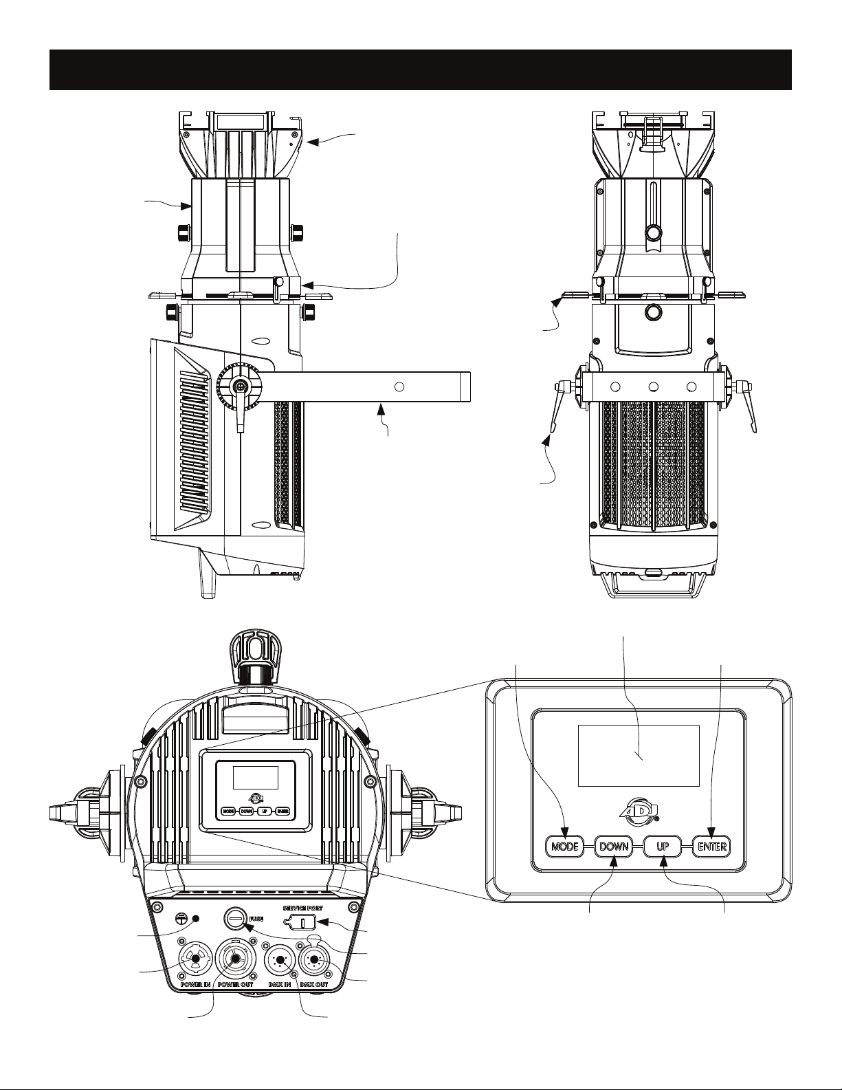
Encore Prole Pro WW Overview
Le ns ( not in cl ud ed)
Fo cu s
Go bo S lot Co ve r
Bl ad e S hutte rs
Mo un ting Yo ke
Yo ke H andl e
LC D M en u C ontr ol D is pla y
MO DE B utto n
EN TE R B utton
Gr ou nd
Po we r I n
Po we r O ut
Se rv ice Port
F u se
5p in D MX OU T
5p in D MX In
8
DO WN B utto n
UP B ut ton
Page 9
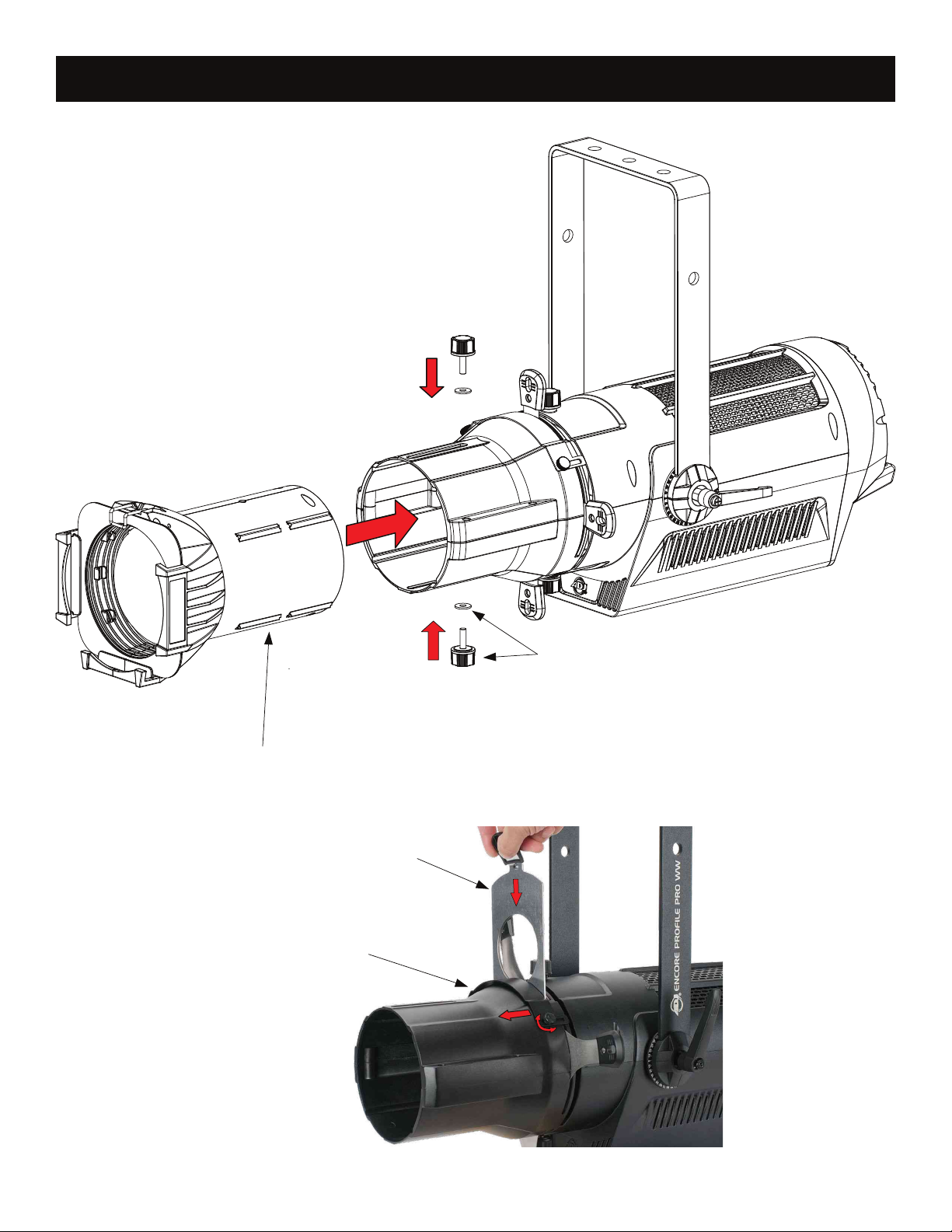
Encore Prole Pro WW Lens & Gobo Installation
Insert the lens kit (not included)
into the lens cone inside.
Gobo Holder
To install Gobo Holder, loosen the
(2x) thumb screws of Gobo Holder
Slot Cover and slide it forward.
Insert (2x) knurled thumb
screws of the lens kit into
their respective gaskets, and
through the bar slots into the
lens kit housing, then tighten.
9
Page 10
Encore Prole Pro WW Installation
FLAMMABLE MATERIAL WARNING
Keep xture minimum 5.0 feet (1.5m) away from ammable materials and/or pyrotechnics.
ELECTRICAL CONNECTIONS
A qualied electrician should be used for all electrical connections and/or installations.
USE CAUTION WHEN POWER LINKING OTHER MODEL FIXTURES AS THE POWER
CONSUMPTION OF OTHER MODEL FIXTURES MAY EXCEED THE MAX POWER OUTPUT
ON THIS FIXTURE. CHECK SILK SCREEN FOR MAX AMPS.
MINIMUM DISTANCE TO OBJECTS/SURFACES
MUST BE 6.6 FEET (2 METERS)
MINIMUM DISTANCE OF INFLAMMABLE MATERIALS
FROM THE SURFACE 1.6 FEET (0.5 METER)
MAXIMUM TEMPERATURE OF EXTERNAL SURFACE 185° F (85°C)
DO NOT INSTALL THE FIXTURE IF YOU ARE NOT QUALIFIED TO DO SO!
Fixture MUST be installed following all local, national, and country commercial electrical and construction codes
and regulations.
Before rigging/mounting a single xture or multiple xtures to any metal truss/structure or placing the xture(s)
on any surface, a professional equipment installer MUST be consulted to determine if the metal truss/structure
or surface is properly certied to safely hold the combined weight of the xture(s), clamps, cables, and
accessories.
Fixture ambient operating temperature range is 14° to 113°F. (-10° to 45°C).
Do not Use xture under or above this temperature.
Fixture(s) should be installed in areas outside walking paths, seating areas, or away from areas were
unauthorized personnel might reach the xture by hand.
NEVER stand directly below the xture(s) when rigging, removing or servicing.
Overhead xture installation must always be secured with a secondary safety attachment, such as an
appropriately rated safety cable.
Allow approximately 60 minutes for the xture to cool down before servicing.
RIGGING
Overhead rigging requires extensive experience, including among others calculating working load
limits, installation material being used, and periodic safety inspection of all installation material and the
xture. If you lack these qualications, do not attempt the installation yourself. Improper installation can
result in bodily injury.
ALWAYS ATTACH AN APPROPRIATELY RATED SAFETY CABLE (NOT INCLUDED) THAT MEETS ALL
LOCAL, NATIONAL, AND COUNTRY CODES AND REGULATIONS WHENEVER INSTALLING FIXTURE
IN A SUSPENDED ENVIRONMENT!
10
Page 11

Encore Profile Pro WW Installation
Encore Prole Pro WW Installation
Always ensure that the unit is rmly xed to avoid vibration and slipping while operating. Always ensure that the
structure to which you are attaching the unit is secure and is able to support a weight of 10 times the unit’s
weight. Always use safety cables that can hold 12 times the weight of the unit when installing the xture. This
equipment must be installed by a professional, and it must be installed in a place where it is out of the reach of
people’s grasp.
The Encore Prole Pro WW is fully operational in three different mounting positions; hanging upside-down,
mounted sideways on trussing, or set on a at level surface. Be sure this xture is kept at least 12m (40ft) away
from any ammable materials (decoration etc.).
OVERHEAD RIGGING: The Encore Prole Pro WW includes two rigging options.
1) OMEGA BRACKET - Mount the xture with an appropriately rated professional grade rigging clamp (not
included) to the included Omega Bracket using an M12 screw and nut (not included). With the rigging clamp
securely attached to the Omega Bracket, attach the Omega Bracket to the xture by inserting both of the 1/4-turn
quick-lock fasteners into the aligning holes on the xture yoke bracket, and turning each clockwise to secure.
MAKE SURE THE OMEGA BRACKET IS SECURELY ATTACHED BEFORE RIGGING FIXTURE!
2) MOUNTING YOKE - Mount the xture with an appropriately rated professional grade rigging clamp (not
included) to the xture yoke bracket center hole using an M12 screw and nut (not included). MAKE SURE THE
CLAMP IS SECURELY ATTACHED BEFORE RIGGING FIXTURE!
SAFETY CABLE: Pull the safety-cable through the opening located on the rear of the unit and over the trussing
system or a safe xation spot. Insert the end in the carabiner and tighten the safety screw. Always use and install
a safety cable as a safety measure to prevent accidental damage and/or injury in the event the clamp fails.
CLAMP INSTALLATION
When mounting xture to truss, be sure to secure an appropriately rated professional grade rigging clamp to
either the included Omega Brackets using an M10 screw tted through the center hole of the Omega Brackets,
or to the Mounting Yoke. The xture provides a built-in rigging point for a SAFETY CABLE (not included). Be
sure to only use one of the designated rigging point for the safety cable and never secure a safety cable to the
carrying handle.
S A F E T Y C A B L E
ALWAYS ATTACH A SAFETY WHENEVER INSTALLING THIS FIXTURE IN A SUSPENDED
ENVIRONMENT TO ENSURE THE FIXTURE WILL NOT FALL IF THE CLAMP FAILS. It’s not enough
that the Safety Cable is attached to the fixture, it must also be routed around the truss or secure
fixation point and both ends securely affixed to the carabiner attached at the built-in rigging point.
Mounting Holes for Omega
Bracket Installation
A Truss Clamp can be
mounted directly to yoke
Safety Cable
(Not included)
11
Page 12
Encore Prole Pro WW Installation
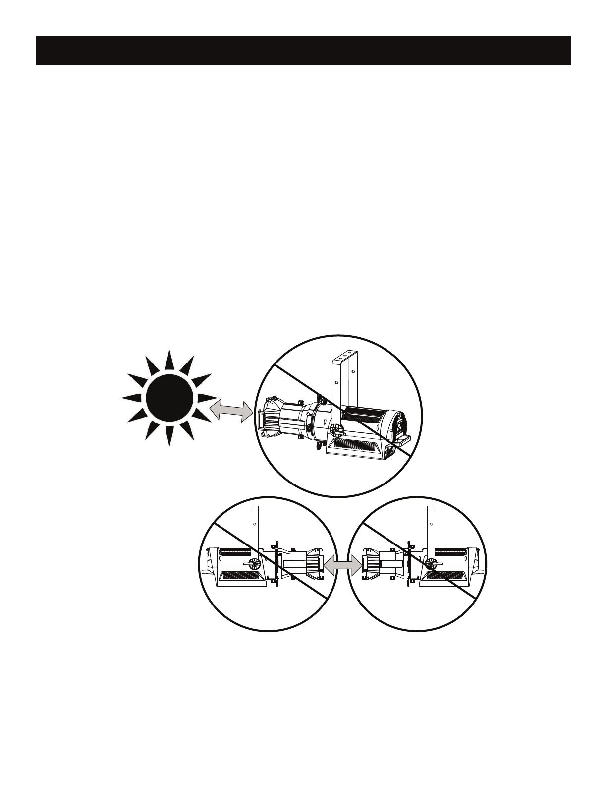
POTENTIAL INTERNAL FIXTURE DAMAGE FROM EXTERNAL SOURCES OF LIGHT BEAMS
External sources of light beams from direct sunlight, lighting moving head xtures, and lasers, which
are focused directly towards the exterior housing and/or penetrate the front lens opening of ADJ lighting
xtures, can cause severe internal damage including burning to optics, dichroic color lters, glass and
metal gobos, prisms, animation wheels, frost lters, iris, shutters, motors, belts, wiring, discharge
lamps, and LEDs.
This issue is not specic to ADJ lighting xtures, it is a common issue with lighting xtures from all
manufacturers. Although there is no true way to fully prevent this issue from happening, the following
guidelines can prevent any potential damage from occurring if followed. Contact ADJ Service for more
details.
DO NOT EXPOSE THE FIXTURE AND/OR FRONT LENS OPENING TO LIGHT BEAMS FROM
DIRECT SUNLIGHT, OTHER LIGHTING MOVING HEAD FIXTURES, AND LASERS WHILE
UNPACKING, INSTALLATION, USE, AND EXTENDED IDLE TIMES OUTDOORS. DO NOT FOCUS
A LIGHT BEAM FROM ONE LIGHTING FIXTURE DIRECTLY TOWARDS ANOTHER.
12
Page 13
Encore Prole Pro WW System Menu
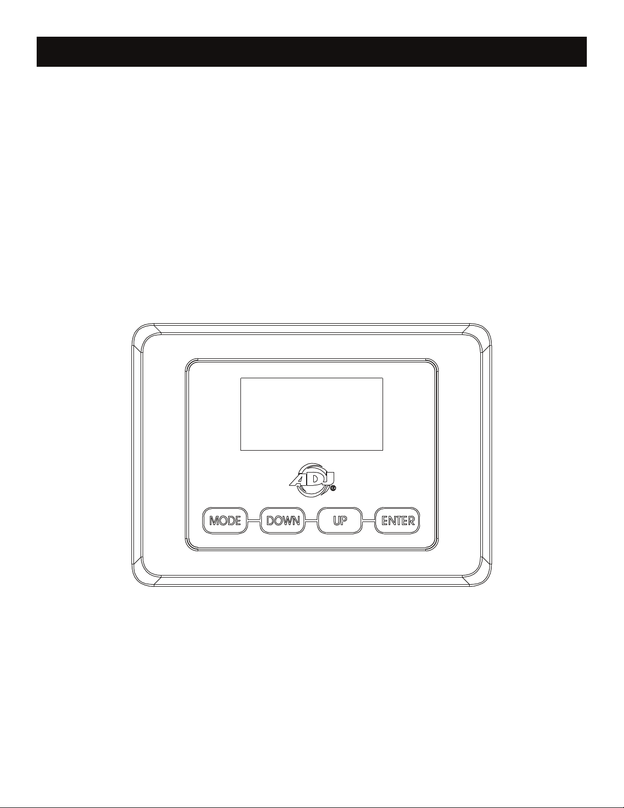
SYSTEM MENU
The xture includes an easy to navigate system-menu control panel display where all necessary settings
and adjustments are made. (See image below) During normal operation, pressing the MENU button once
will access the xture’s main menu. Once in the main menu, you can navigate through the different
menu’s with the UP, DOWN, and MENU buttons. When you reach a eld that requires adjusting, press
the ENTER button to access that eld and use the UP and DOWN buttons to adjust the eld. Pressing
the ENTER button once more to conrm your setting. You may exit the menu’s at any time without
making any adjustments by pressing the MENU button.If there are no changes/adjustments made within
10 seconds, the unit will revert back to the setting made under “No DMX State”.
13
Page 14

Encore Prole Pro WW System Menu
Supports Software Versions: 1.02
MENU OPTIONS / VALUES (Default Settings in BOLD) DESCRIPTION
Shall be used to set the units starting
DMX address channel. Depending
DMX Address
001 001 - 512
on set DMX mode, unit shall not
allow to be addressed any higher
that will not allow for all channels to
be accessed from the console.
DMX Channel Mode 2CH/3CH/6CH
Status Lost Dmx
LCD Set
Disp Set
Temp.C/F
Dim Mode
Personality
Dim Curve
Frequen
Black/Hold
Display
Key Lock
Flash
Invert
Address
Chan. Val
MastSlav
C/F
Standard
Stage
TV
Architec
Theatre
Stage 2
Dim Spd 0-10s
Linear
Square
Inv.Squa
S. Curve
900HZ, 1000HZ, 1100HZ, 1200HZ, 1300HZ,
1400HZ, 1500HZ, 2500HZ, 4000HZ, 5000HZ,
10KHZ, 15KHZ, 20KHZ, 25KHZ
ON/OFF
ON/OFF
ON/OFF
ON/OFF
Starting DMX Address
Shall display last active DMX value
Master / Slave
Shall be used to set the units desired
DMX mode.
No dmx status
30S blackout display
No DMX Flash
Screen 180°ip
Manual Control
Service
Info
MasterSw
USB_Data
DFSE
ManCtrl
Calibrat
Time Info
TempInfo xxxF/xxxC
Err.Info None. Temp
ModelInf Encore Prole Pro WW
Software V1.02
ON/OFF
ON/OFF
ON/OFF
Strobe=XXX
Dimmer=XXX
Password (50)
WW LED = XXX
Current Current xture running time(H)
Total Fixture total running time(H)
Last Clear last xture running time(h)
Password
Clear
Master transmit the signal(should be
on then can do the master & slave)
Default Setting
Clear 0 (clear the current running
time Password = 050, total running
time = 060)
ON/OFF
14
Page 15

Encore Prole Pro WW System Menu
DMX Address - In this menu you can nd and set your desired DMX address.
Channel Mode - In this menu you can nd and set your desired DMX channel mode.
Function Status - This menu setting is used as a precaution mode in case the DMX signal is lost or
interrupted. The operating mode chosen in this menu is the running mode the xture will go into when
the DMX signal is lost. Listed below are the 3 modes.
• Hold - This setting will have the xture stay in the last DMX setup.
• Black - This setting will have the xture automatically go into stand by mode.
LCD Set - In this menu you are able to activate/deactivate the display blackout and activate/deactivate the dis‐
play lock.
Temp.C/F - Set temperature display between Celsius and Fahrenheit.
Dim Mode - In this menu you are able to select your desired dimmer mode and adjust the dimming
speed time.
Disp. Set - In this menu you are able to activate/deactivate the display blackout and activate/deactivate the dis‐
play lock.
Dim Curve - Set Dimming Curve
Frequen - Set xture frequency.
MasterSW- This transmits the DMX signal via a master & slave control hierarchy.
Service - In this menu you are able to access and adjust/change: the calibration (effect adjust) and
restore the factory settings.
USB_Data - Turns USB data access on or off.
DFSE - Turns Default Setting on or off.
Time Info - Select between Current xture running time and Fixture total running time. Only the Fix‐
ture Current xture running time can be cleared
TempInfo - Displays xture temperature.
Err.Info - Displays xture error information.
ModelInf - Displays xture information.
Software - Displays current software version.
ManCTRL - Manual Dimmer Control.
Strobe=XXXX - Test Strobe Effect.
Calibrate - Calibrate LED, password protected.
15
Page 16

Encore Prole Pro WW Multiple Unit Power Linking
With this feature you can connect the xtures to one another using the power cable input and
output sockets.
NOTE: USE CAUTION WHEN POWER LINKING OTHER FIXTURES AS THE POWER
CONSUMPTION OF OTHER MODEL FIXTURES MAY EXCEED THE MAXIMUM POWER OUTPUT
ON THIS FIXTURE! CHECK SILK SCREEN FOR MAXIMUM AMPERES.
Encore Prole Pro WW Dimmer Mode Chart
DIMMER
100%
50%
10%
0%
Time (ms)
0 Sec Rise Time Down Time
0 sec Fade Time 1 sec Fade Time
255
Dimming Curve Ramp
Effect
0
0
Rise Time (ms) Down Time (ms) Rise Time (ms) Down Time (ms)
Standard (default) 0 0 0 0
Stage 780 1100 1540 1660
TV 1180 1520 1860 1940
Architectural 1380 1730 2040 2120
Theatre 1580 1940 2230 2280
Stage 2 0 1100 0 1660
255
16
Page 17

Encore Profile Pro WW DMX Set Up
DMX-512: DMX is short for Digital Multiplex. This is a universal protocol used as a form of communication
between intelligent fixtures and controllers. A DMX controller sends DMX data instructions from the
controller to the fixture. DMX data is sent as serial data that travels from fixture to fixture via the
DATA “IN” and DATA “OUT” XLR terminals located on all DMX fixtures (most controllers only have a
DATA “OUT” terminal).
DMX Linking: DMX is a language allowing all makes and models of different manufactures to be
linked together and operate from a single controller, as long as all xtures and the controller are DMX
compliant. To ensure proper DMX data transmission, when using several DMX fixtures try to use the
shortest cable path possible. The order in which fixtures are connected in a DMX line does not
influence the DMX addressing. For example; a fixture assigned a DMX address of 1 may be placed
anywhere in a DMX line, at the beginning, at the end, or anywhere in the middle. When a fixture is
assigned a DMX address of 1, the DMX controller knows to send DATA assigned to address 1 to that
unit, no matter where it is located in the DMX chain.
Data Cable (DMX Cable) Requirements (For DMX Operation): The Encore Prole Pro WW can be controlled
via DMX-512 protocol. The Encore Prole Pro WW has multiple DMX channel modes. Your unit and
your DMX controller requires a 5-pin XLR connector for data input and data output. If you are making your
own cables, be sure to use standard 110-120 Ohm shielded cable (This cable may be purchased at
almost all pro lighting stores). Your cables should be made with a male and female XLR connector on
either end of the cable. Also remember that DMX cable must be daisy chained and cannot be split.
Special Note: Line Termination.
on the last unit to avoid erratic behavior. A terminator is a 110-120 ohm 1/4 watt resistor which is connected
between pins 2 and 3 of a male XLR connector (DATA + and DATA -). This unit is inserted in the female
XLR connector of the last unit in your daisy chain to terminate the line. Using a cable terminator (ADJ
part number Z-DMX/T) will decrease the possibilities of erratic behavior.
When longer runs of cable are used, you may need to use a terminator
17
Page 18

Encore Profile Pro WW DMX Addressing
DMX ADDRESSING
All xtures should be given a DMX starting address when using a DMX controller, so the correct xture
responds to the correct control signal. This digital starting address is the channel number from which
the xture starts to “listen” to the digital control signal sent out from the DMX achieved by setting the
correct DMX address on the digital control display on the xture.
You can set the same starting address for all xtures or a group of xtures, or set different addresses
for each individual xture. Setting all xtures to the same DMX address will cause all xtures to react
in the same way, in other words, changing the settings of one channel will affect all the xtures
simultaneously.
If you set each xture to a different DMX address, each unit will start to “listen” to the channel number you
have set, based on the quantity of DMX channels of each xture. That means changing the settings of one
channel will only affect the selected xture.
18
Page 19

Encore Profile Pro WW DMX Channel Functions & Values
Supports Software Versions: ≥ 1.02
Features subject to change without notice.
MODE/CHANNEL
2CH 3CH 6CH
1 1 1
2 2 2 000‐255 Dimmer Fine 16bit
3 3
4
VALUE FUNCTION
Dimmer Intensity 8bit
000-255 0 to 100%
Shutter
000-031 Shutter Closed (LEDs OFF)
032-063 Shutter OPEN (LEDs ON)
064-095 Strobe effect slow to fast
096-127 Shutter OPEN (LEDs ON)
128-159 Pulse effect in sequences
160-191 Shutter OPEN (LEDs ON)
192-223 Random strobe effect slow to fast
224-255 Shutter OPEN (LEDs ON)
248–255 Open
Dim Modes
000-020 Standard
021-040 Stage
041-060 TV
061-080 Architectural
081-100 Theatre
101-120 Stage 2
Dimming Speed
121 0.1Sec.
122 0.2Sec.
123 0.3Sec.
124 0.4Sec.
125 0.5Sec.
126 0.6Sec.
127 0.7Sec.
128 0.8Sec.
129 0.9Sec.
130 1.0Sec.
131 1.5Sec.
132 2.0Sec.
133 3.0Sec.
134 4.0Sec.
135 5.0Sec.
136 6.0Sec.
137 7.0Sec.
138 8.0Sec.
139 9.0Sec.
140 10Sec.
141-255 Default to Unit Setting
19
Page 20

Encore Profile Pro WW DMX Channel Functions & Values
Features subject to change without notice.
MODE/CHANNEL
2CH 3CH 6CH
5
6
VALUE FUNCTION
Dim Curves
000-020 Linear
021-040 Square
041-060 Inv. Squa
061-080 S. Curve
081-255 No Function
LED Refresh Rates
029-029 1080 Hz LED Refresh Rate
030-030 1090 Hz LED Refresh Rate
031-031 1100 Hz LED Refresh Rate
032-032 1110 Hz LED Refresh Rate
033-033 1120 Hz LED Refresh Rate
034-034 1130 Hz LED Refresh Rate
035-035 1140 Hz LED Refresh Rate
036-036 1150 Hz LED Refresh Rate
037-037 1160 Hz LED Refresh Rate
038-038 1170 Hz LED Refresh Rate
039-039 1180 Hz LED Refresh Rate
040-040 1190 Hz LED Refresh Rate
041-041 1210 Hz LED Refresh Rate
042-042 1220 Hz LED Refresh Rate
043-043 1230 Hz LED Refresh Rate
044-044 1240 Hz LED Refresh Rate
045-045 1250 Hz LED Refresh Rate
046-046 1260 Hz LED Refresh Rate
047-047 1270 Hz LED Refresh Rate
048-048 1280 Hz LED Refresh Rate
049-049 1290 Hz LED Refresh Rate
050-050 1300 Hz LED Refresh Rate
051-051 1310 Hz LED Refresh Rate
052-052 1320 Hz LED Refresh Rate
053-053 1330 Hz LED Refresh Rate
054-054 1340 Hz LED Refresh Rate
055-055 1350 Hz LED Refresh Rate
056-056 1360 Hz LED Refresh Rate
057-057 1370 Hz LED Refresh Rate
058-058 1380 Hz LED Refresh Rate
059-059 1390 Hz LED Refresh Rate
060-060 1400 Hz LED Refresh Rate
061-061 1410 Hz LED Refresh Rate
062-062 1420 Hz LED Refresh Rate
063-063 1430 Hz LED Refresh Rate
064-064 1440 Hz LED Refresh Rate
065-065 1450 Hz LED Refresh Rate
066-066 1460 Hz LED Refresh Rate
067-067 1470 Hz LED Refresh Rate
068-068 1480 Hz LED Refresh Rate
20
Page 21

Encore Profile Pro WW DMX Channel Functions & Values
Features subject to change without notice.
MODE/CHANNEL
2CH 3CH 6CH
6
VALUE FUNCTION
069-069 1490 Hz LED Refresh Rate
070-070 1500 Hz LED Refresh Rate
071-071 2500 Hz LED Refresh Rate
072-072 4000 Hz LED Refresh Rate
073-073 5000 Hz LED Refresh Rate
074-074 6000 Hz LED Refresh Rate
075-075 10K Hz LED Refresh Rate
076-076 15K Hz LED Refresh Rate
077-077 20K Hz LED Refresh Rate
078-078 25K Hz LED Refresh Rate
079-079 Disable LED Refresh Rate
080-255 No Function
21
Page 22

Encore Profile Pro WW Specifications
SOURCE
260W Warm White LED Engine
50,000 Hour Average LED Life*
*LED Life may vary depending on several factors including but not limited to:
Environmental Conditions, Power/Voltage, Usage Patterns (On-Off Cycling), Control, and Dimming.
PHOTOMETRIC DATA
>97CRI 10,000 Total Lumens* (*with 26° lens)
3200K Color Temperature
EFFECTS
Electronic Strobe and Dimming
Variable Dimming Curves and Dimming Modes
GOBOS
Supports “B” Size Metal, HT Transparency Gobos*
*Gobos and Holder not included.
CONTROL / CONNECTIONS
(3) DMX Channel Modes (1 / 3 / 4)
Adjustable Refresh Rates (900-1500, 25,000 Hz)
4 Button Control Panel
LED Menu Display
Locking 5pin XLR Connector In/Out
Locking Power Connector In/Out
With Wired Digital Communication Network
SIZE / WEIGHT
Length: 26.9” (688mm) (Lens In)
Width: 111.3” (287mm)
Vertical Height: 17.7” (450mm)
Weight: 20.0 lbs. (9.1 kg)
ELECTRICAL / THERMAL
Quiet Fan Cooling
AC 100-240V - 47/63Hz
260W Max Power Consumption
Power Linking: 3pcs Max @120V / 8pcs Max @240V
14° to 113°F (-10° to 45°C)
APPROVALS / RATINGS
CE | cETLus (Pending) | IP30
INCLUDED ITEMS
(1) Locking Power Cable
OPTIONAL ACCESSORIES:
SKU# Models
EPL005 EP Lens 5 (5° Lens)
EPL010 EP Lens 10 (10° Lens)
EPL140 EP Lens 14 (14° Lens).
EPL190 EP Lens 19 (19° Lens)
EPL260 EP Lens 26 (26° Lens)
EPL360 EP Lens 36 (36° Lens)
EPL500 EP Lens 50 (50° Lens)
EPL549 EP Lens 15-30 (Adjustable 15° to 30° Lens Assembly)
EPL525 EP Lens 25-50 (Adjustable 25° to 50° Lens Assembly)
Specications and documentation subject to change without notice.
22
Page 23

Encore Profile Pro WW Dimensions
26.9in. [683mm]
22.2in. [563mm]
1.7in. [42mm]
9.8in. [250mm]
1.0in. [26mm]
11.4in. [289mm]
7.9in. [200mm]
12.7in. [323mm]
23
17.7in. [450mm]
Page 24
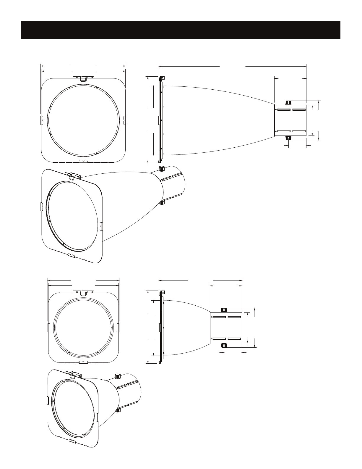
Encore Profile Pro WW Optional Lens Kit Dimensions
Lens Kits are not included
LENS KIT: 5°
14.3in. [362.0mm
14.1in. [357mm]
14.5in. [367.5mm]
11.5in. [293.0mm]
24.7in. [626.5mm]
5.3in. [135.1mm]
3.0in. [76mm]
6.6in. [167mm]
5.1in. [130mm]
11.9in. [303.0mm]
11.7in. [298mm]
LENS KIT: 10°
13.8in. [351.5mm]
9.2in. [233.0mm]
12.1in. [308.5mm]
5.3in. [135.1mm]
3.0in. [76mm]
6.6in. [167mm]
5.1in. [130mm]
24
Page 25

Encore Profile Pro WW Optional Lens Kit Dimensions
Lens Kits are not included
LENS KIT: 14°
8.7in. [222.0mm]
8.5in. [217mm]
10.7in. [271.1mm]
5.3in. [135.1mm]
6.6in. [167mm]
9.0in. [227.5mm]
7.3in. [184.5mm]
3.0in. [76mm]
5.1in. [130mm]
6.8in. [172.0mm]
6.3in. [159mm]
LENS KIT: 19°, 26°, 36°, 50°
9.7in. [247.4mm]
6.8in. [172.0mm]
3.0in. [77mm]
6.1in. [154.2mm]
6.6in. [167mm]
5.1in. [130mm]
25
Page 26

Encore Profile Pro WW Optional Lens Kit Dimensions
Lens Kits are not included
ZOOM LENS KIT: 15° - 30°
10.0in. [255.0mm]
6.9in. [175.0mm]
19.6in. [496.8mm]
1.9in. [48.6mm]
7.5in. [190.0mm]
6.3in. [161.0mm]
10.0in. [255.0mm]
6.9in. [175.0mm]
ZOOM LENS KIT: 25° - 50°
14.7in. [374.3mm]
1.9in. [48.6mm]
7.5in. [190.0mm]
6.3in. [161.0mm]
26
Page 27

Encore Profile Pro WW Troubleshooting
Listed below are a few common problems the user may encounter, with solutions.
Unit not powered on:
• Check that the xture is plugged in.
Unit not responding to DMX:
• Check that the DMX cables are connected properly and are wired correctly (pin 3 is “hot”; on
some other DMX devices pin 2 may be ‘hot’). Also, check that all cables are connected to the right
connectors; it does matter which way the inputs and outputs are connected.
Encore Profile Pro WW Cleaning
DISCONNECT POWER BEFORE PERFORMING ANY MAINTENANCE!
CLEANING
Frequent cleaning is recommended to ensure proper function, optimized light output, and an
extended life. The frequency of cleaning depends on the environment in which the xture operates:
damp, smoky, or particularly dirty environments can cause greater accumulation of dirt on the xture’s
optics. Clean the external lens surface periodically with a soft cloth to avoid dirt/debris accumulation.
NEVER use alcohol, solvents, or ammonia-based cleaners.
Encore Profile Pro WW Maintenance
MAINTENANCE
Regular inspections are recommended to ensure proper function and extended life.
There are no user serviceable parts inside this xture, please refer all other service issues to an
authorized ADJ service technician. Should you need any spare parts, please order genuine parts from
your local ADJ dealer.
Please refer to the following points during routine inspections:
- A detailed electrical check by an approved electrical engineer every three months, to make sure the
circuit contacts are in good condition in order to prevent overheating.
- Be sure all screws and fasteners are securely tightened at all times. Loose screws may fall out during
normal operation, resulting in damage or injury as larger parts could fall.
- Check for any deformations on the housing, color lenses, rigging hardware, and rigging points
(ceiling, suspension, trussing). Deformations in the housing could allow for dust or liquids to enter
into the xture. Damaged rigging points or unsecured rigging could cause xture to fall and
seriously injure a person(s).
- Electric power supply cables must not show any damage, material fatigue, or sediments.
- NEVER remove the ground prong from the power cable.
27
Page 28

 Loading...