

Page 1
1
COB CANNON WASH ST
user manual
Page 2

2
©2018 ADJ PRODUCTS LLC all rights reserved. Information, specifications, diagrams, images, and
instructions herein are subject to change without notice. ADJ logo and identifying product names
and numbers herein are trademarks of ADJ PRODUCTS LLC. Copyright protection claimed includes
all forms and matters of copyrightable materials and information now allowed by statutory or judicial
law or hereinafter granted. Product names used in this document may be trademarks or registered
trademarks of their respective companies and are hereby acknowledged. All non-ADJ brands and
product names are trademarks or registered trademarks of their respective companies.
ADJ PRODUCTS LLC and all affiliated companies hereby disclaim any and all liabilities for property,
equipment, building, and electrical damages, injuries to any persons, and direct or indirect economic
loss associated with the use or reliance of any information contained within this document, and/or as
a result of the improper, unsafe, insufficient and negligent assembly, installation, rigging, and
operation of this product.
ADJ PRODUCTS LLC USA
6122 S. Eastern Ave. Los Angeles, CA 90040
323-582-2650 | Fax 323-532-2941 | www.adj.com | info@adj.com
ADJ SUPPLY Europe B.V
Junostraat 2 6468 EW Kerkrade, The Netherlands
+31 (0)45 546 85 00 | Fax +31 45 546 85 99 | www.adj.eu | info@americandj.eu
ADJ PRODUCTS GROUP Mexico
AV Santa Ana 30 Parque Industrial Lerma, Lerma, Mexico 52000
+52 (728) 282-7070 | ventas@adj.com
CUSTOMER SUPPORT
Contact ADJ Service for any product related service and support needs.
Please visit forums.adj.com with questions, comments or suggestions.
ADJ SERVICE USA - Monday - Friday 8:00am to 4:30pm PST
800-322-6337 | Fax 323-832-2941 | support@adj.com
ADJ SERVICE EUROPE - Monday - Friday 08:30 to 17:00 CET
+31 45 546 85 60 | Fax +31 45 546 85 96 | support@adj.eu
REPLACEMENT PARTS please visit parts.americandj.com
Page 3
3
DOCUMENT VERSION
Date
Document Version
Notes
11/29/18
1.1
Updated release.
An updated version of this document may be available online.
Please check www.adj.com for the latest revision/update of this document before
beginning installation and use.
FCC STATEMENT
This device complies with Part 15 of the FCC Rules. Operation is subject to the following two
conditions: (1) this device may not cause harmful interference, and (2) this device must accept any
interference received, including interference that may cause undesired operation.
FCC RADIO FREQUENCY INTERFERENCE WARNINGS & INSTRUCTIONS
This product has been tested and found to comply with the limits as per Part 15 of the FCC Rules.
These limits are designed to provide reasonable protection against harmful interference in a
residential installation. This device uses and can radiate radio frequency energy and, if not installed
and used in accordance with the included instructions, may cause harmful interference to radio
communications. However, there is no guarantee that interference will not occur in a particular
installation. If this device does cause harmful interference to radio or television reception, which can
be determined by turning the device off and on, the user is encouraged to try to correct the
interference by one or more of the following methods:
•! Reorient or relocate the device.
•! Increase the separation between the device and the receiver.
•! Connect the device to an electrical outlet on a circuit different from which the radio receiver is
connected.
•! Consult the dealer or an experienced radio/TV technician for help.
Energy Saving Matters (EuP 2009/125/EC)
Saving electric energy is a key to help protecting the environment. Please turn off all electrical
products when they are not in use. To avoid power consumption in idle mode, disconnect all
electrical equipment from power when not in use. Thank you!
Page 4

4
CONTENTS
General Information
5
Limited Warranty (USA Only)
6
Safety Guidelines
7
Maintenance Guidelines
9
Overview
10
DMX Setup
11
Installation Instructions
13
System Menu
14
DMX Channels / Values / Functions
18
Dimmer Curve Chart
22
UC IR Control and Airstream Control
23
Multiple Unit Power Linking
24
Master / Slave Set up
24
Optional Lens / Fuse Replacement / Cleaning
24
Trouble Shooting Tips and FAQ
25
Tech ni ca l Sp ec if ica ti on s an d Op ti on al Accessories
26
Dimensions
27
Page 5

5
GENERAL INFORMATION
INTRODUCTION
Please read and understand all instructions in this manual carefully and thoroughly before attempting
to operate these products. These instructions contain important safety and use information.
UNPACKING
The products in this kit have been thoroughly tested and have been shipped in perfect operating
condition. Carefully check the shipping carton for damage that may have occurred during shipping.
If the carton appears to be damaged, carefully inspect each unit included for damage and be sure all
accessories necessary to operate the units have arrived intact. In the event damage has been found
or parts are missing, please contact our customer support team for further instructions. Please do
not return this kit to your dealer without first contacting customer support at the number listed below.
Please do not discard the shipping carton in the trash. Please recycle whenever possible.
WARRANTY RETURNS
All returned service items whether under warranty or not, must be freight pre-paid and accompany a
return authorization (R.A.) number. The R.A. number must be clearly written on the outside of the
return package. A brief description of the problem as well as the R.A. number must also be written
down on a piece of paper and included in the shipping container. If the unit is under warranty, you
must provide a copy of your proof of purchase invoice. Items returned without a R.A. number clearly
marked on the outside of the package will be refused and returned at customer’s expense. You may
obtain a R.A. number by contacting customer support.
Page 6

6
LIMITED WARRANTY (USA ONLY)
A.! ADJ Products, LLC hereby warrants, to the original purchaser, ADJ Products, LLC products to be free of
manufacturing defects in material and workmanship for a prescribed period from the date of purchase (see specific
warranty period on reverse). This warranty shall be valid only if the product is purchased within the United States
of America, including possessions and territories. It is the owner’s responsibility to establish the date and place of
purchase by acceptable evidence, at the time service is sought.
B.! For warranty service, you must obtain a Return Authorization number (RA#) before sending back the
product-please contact ADJ Products, LLC Service Department at 800-322-6337. Send the product only to
the ADJ Products, LLC factory. All shipping charges must be pre-paid. If the requested repairs or service (including
parts replacement) are within the terms of this warranty, ADJ Products, LLC will pay return shipping charges only
to a designated point within the United States. If the entire instrument is sent, it must be shipped in its original
package. No accessories should be shipped with the product. If any accessories are shipped with the product,
ADJ Products, LLC shall have no liability whatsoever for loss of or damage to any such accessories, or for the safe
return thereof.
C.! This warranty is void of the serial number has been altered or removed; if the product is modified in any manner
which ADJ Products, LLC concludes, after inspection, affects the reliability of the product, if the product has been
repaired or service by anyone other than ADJ Products, LLC factory unless prior written authorization was issued
to purchaser by ADJ Products, LLC; if the product is damaged because not properly maintained as set forth in the
instruction manual.
D.! This is not a service contact, and this warranty does not include maintenance, cleaning or periodic check up.
During the period specified above, ADJ Products, LLC will replace defective parts at its expense with new or
refurbished parts, and will absorb all expenses for warrant service and repair labor by reason of defects in material
or workmanship. The sole responsibility of ADJ Products, LLC under this warranty shall be limited to the repair of
the product, or replacement thereof, including parts, at the sole discretion of ADJ Products, LLC. All products
covered by this warranty were manufactured after August 15, 2012, and bear identifying marks to that effect.
E.! ADJ Products, LLC reserves the right to make changes in design and/or improvements upon its products without
any obligation to include these changes in any products theretofore manufactured.
F.! No warranty, whether expressed or implied, is given or made with respect to any accessory supplied with products
described above. Except to the extent prohibited by applicable law, all implied warranties made by ADJ Products,
LLC in connection with this product, including warranties of merchantability or fitness, are limited in duration to the
warranty period set forth above. And no warranties, whether expressed or implied, including warranties of
merchantability or fitness, shall apply to this product after said period has expired. The consumer’s and/or Dealer’s
sole remedy shall be such repair or replacement as is expressly provided above; and under no circumstances shall
ADJ Products, LLC be liable for any loss or damage, direct or consequential, arising out of the use of, or inability to
use, this product.
G.! This warranty is the only written warranty applicable to ADJ Products, LLC Products and supersedes all prior
warranties and written descriptions of warranty terms and conditions heretofore published.
LIMITED WARRANTY PERIODS
•! Non L.E.D. Lighting
Intelligent Lighting, UV lighting, Strobes, Fog Machines, Bubble Machines, Mirror Balls, Par Cans, Trussing,
Lighting Stands etc. excluding LED and lamps)
•! Laser
•! L.E.D.
Note: 2 Year
•! StarTec Series = 1 Year Limited
•! ADJ DMX
Products
Products
Warranty
Controllers
Products
= 1 Year (365 Days) Limited
= 2-year (730 days) Limited
only applies to
= 2 Year (730 Days) Limited Warranty
= 1-year (365 days) Limited
Warranty (excludes laser diodes which have 6 month limited
Warranty (excluding batteries which have a 180 day limited
purchases
Warranty (excluding batteries which have a 180 day limited warranty)
Warranty (Such as: Special Effect Lighting,
within the United
States.
warranty)
warranty)
Page 7
7
SAFETY INSTRUCTIONS AND GUIDELINES
To guarantee a smooth operation, it is important to follow all instructions and guidelines in this
manual. ADJ PRODUCTS LLC is not responsible for injury and/or damages resulting from the
misuse of these devices due to the disregard of the information printed in this manual. Only qualified
and/or certified personnel should perform installation of these devices and only the original rigging
parts included with these devices should be used for installation. Any modifications to these devices
and/or the included mounting hardware will void the original manufactures warranty and increase the
risk of damage and/or personal injury.
PROTECTION CLASS 1 – DEVICES MUST BE PROPERLY GROUNDED
THERE ARE NO USER SERVICEABLE PARTS INSIDE THESE DEVICES. DO NOT
ATTEM PT AN Y R EPAI RS YOURSELF; DOING SO WILL VOID YOUR
MANUFACTURES WARRANTY. D A M A G E S R E S U L T I N G FROM MODIFICATIONS TO
THESE DEVICES AND/OR THE DISREGARD OF SAFETY INSTRUCTIONS AND
GUIDELINES IN THIS MANUAL VOID THE MANUFACTURES WARRANTY AND ARE
NOT SUBJECT TO ANY WARRANTY CLAIMS AND/OR REPAIRS.
DO NOT PLUG THIS UNIT INTO A DIMMER PACK!
DO NOT REMOVE THE COVER UNDER ANY CONDITIONS!
NEVER OPERATE THIS UNIT WITH THE COVER REMOVED!
UNPLUG POWER DURING LONG PERIODS OF NON-USE
NEVER TOUCH LIGHT DURING OPERATION, AS IT MAY BE HOT!
KEEP FLAMMABLE MATERIALS AWAY FROM THESE DEVICES!
DO NOT EXCEED OPERATING TEMPERATURES OF 185°F (85°C)!
INDOOR / DRY LOCATIONS USE ONLY!
DO NOT EXPOSE DEVICES TO RAIN AND/OR MOISTURE!
NEVER LOOK DIRECTLY INTO THE LIGHT SOURCE!
RETINA INJURY RISK - MAY INDUCE BLINDNESS!
SENSITIVE PERSONS MAY SUFFER AN EPILEPTIC SHOCK!
Page 8

8
SAFETY INSTRUCTIONS AND GUIDELINES
DO NOT position devices close to any FLAMMABLE MATERIALS while operating.
DO NOT attempt installation and/or operation of devices without knowledge how to do so.
DO NOT permit operation by persons who are not qualified to operate these types of devices.
DO NOT shake devices, avoid brute force when installing and/or operating.
DO NOT operate these devices if the main power cord has become frayed, crimped and/or
damaged. Replace any damaged power cords with a similar power rating.
DO NOT remove or break-off the ground plug from the device power cords.
DO NOT remove disassemble devices, there are NO user serviceable parts inside.
ALWAYS disconnect devices from main power source before performing any cleaning.
ALWAYS disconnect light from main power before replacing lamp.
ALWAYS be sure to install these devices in an area that will allow proper ventilation.
NEVER remove the ground prong from the power cable.
Power cords should be safely routed and secured so they are not likely pinched.
Disconnect power cords during long periods of non-use.
Only use recommended rigging hardware as described in this guide.
Use the original packaging and materials to transport these devices in for service.
These devices should be serviced by qualified service personnel when:
•! The power cords or plugs have become damaged.
•! Objects have fallen on and/or liquid has spilled into the devices.
•! The devices have been exposed to rain and/or moisture.
•! The devices do not operate normally or exhibit a marked change in performance.
Page 9

9
MAINTENANCE GUIDELINES
DISCONNECT POWER BEFORE PERFORMING ANY MAINTENANCE!
CLEANING
Frequent cleaning is recommended to insure proper function, optimized light output, and an
extended life. The frequency of cleaning depends on the environment in which the device operates
in: damp, smoky or particularly dirty environments can cause greater accumulation of dirt on the lens
and/or light fixture optics. Clean the external housing of the fixture and the front lens of the light at
least every 20 days with a soft cloth to avoid dirt/debris accumulation.
NEVER use alcohol, solvents, or ammonia-based cleaners.
MAINTENANCE
Regular inspections are recommended to insure proper function and extended life.
There are no user serviceable parts inside these devices, please refer all other service issues to an
authorized ADJ service technician. Should you need any spare parts, please order genuine parts
from your local ADJ dealer.
Please refer to the following points during routine inspections:
A detailed review by an approved electrical engineer every three months, to make sure the circuit
contacts are in good condition and prevent overheating.
Be sure all screws and fasteners are securely tightened at all times. Lose screws may fall out during
normal operation resulting in damage or injury as larger parts could fall.
Check for any deformations on the light, light housings, lenses, rigging hardware and rigging points
(ceiling, suspension, trussing). Deformations could allow for dust to enter into the devices. Damaged
rigging points or unsecured rigging could cause the devices to fall and seriously injure a person(s).
Electric power supply cables must not show any damage, material fatigue or sediments.
Page 10

10
OVERVIEW
MENU
To select the programming functions
SET UP
To go forward in the selected functions
UP
To go backward in the selected functions
DOWN
To go forward in the selected functions
4 5 6
3 2
1
Display: Show the various menus and the selected functions.
1 -
2 – Button:
3 – Fuse:
4 – DMX Input/output
5 – DMX Input/output
6 – Mains Input/output
3 Amps.
:3-Pin In/Out Connection
:5-Pin In/Out Connection
:Use powerCON mains connection.
Page 11
11
DMX SETUP
Figure 1
POWER SUPPLY
The COB Cannon Wash ST contains an automatic voltage switch, which will auto sense the voltage
when it is plugged into the power source. With this switch there is no need to worry about the correct
power voltage, this unit can be plugged in anywhere.
DMX-512
DMX is short for Digital Multiplex. This is a universal
manufactures as a form
of
communication between intelligent fixtures and controllers. A DMX
controller sends DMX data instructions from the controller to the fixture. DMX data is sent as serial
data that travels from fixture to fixture via the DATA “IN” and DATA “OUT” XLR terminals located on
all DMX fixtures (most controllers only have a DATA “OUT” terminal).
DMX LINKING
DMX is a language allowing all makes and models of different manufactures to be linked
together and operate from a single controller, as long as all fixtures and the controller are DMX
compliant. To ensure proper DMX data transmission, when using several DMX fixtures try to
use the shortest cable path possible. The order in which fixtures are connected in a DMX line does
not influence the DMX addressing. For example, a fixture assigned a DMX address of 1 may be
placed anywhere in a DMX line, at the beginning, at the end, or anywhere in the middle. Therefore,
the first fixture
contr
olled by the controller could be the last fixture in the chain. When a fixture is
assigned a DMX address of 1, the DMX controller knows to send DATA assigned to address 1 to
that unit, no matter where it is located in the DMX chain.
DATA CABLE (DMX CABLE) REQUIREMENTS
(FOR DMX AND MASTER/SLAVE OPERATION):
The COB Cannon Wash ST can be controlled via DMX-512
protocol. The COB Cannon Wash ST has three DMX
channel modes (1 channel mode, 2 channel mode, & 3
channel mode). The DMX address is set electronically using
the controls on the rear panel of the unit. Your unit and your
DMX controller require an approved DMX-512 110 Ohm
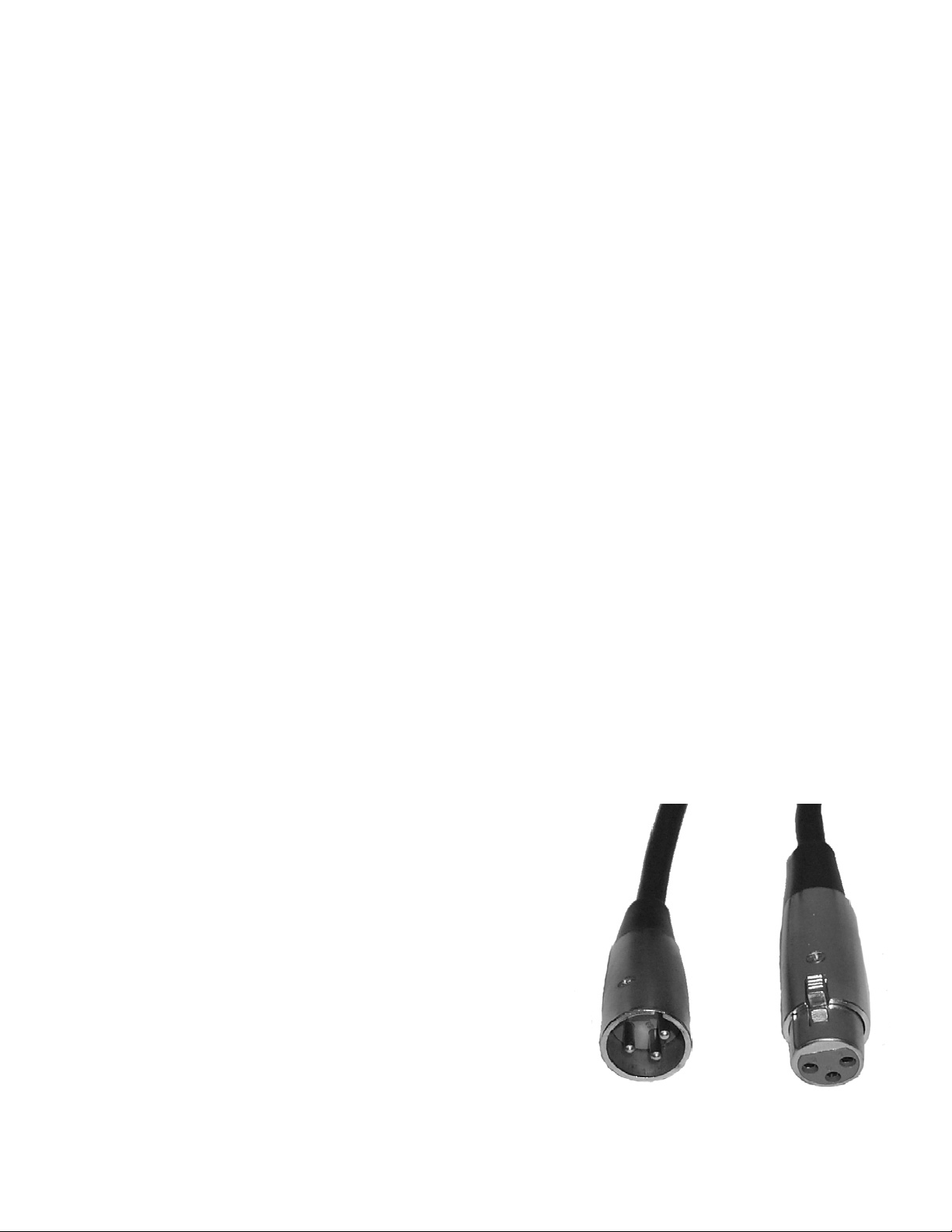
Data cable for data input and data output (Figure 1). We
recommend AccuCable DMX cables. If you are making your
own cables, be sure to use standard 110-120 Ohm shielded
cable (This cable be purchased at almost all professional
sound and lighting stores). Your cables should be made with
a male and female XLR connector on either end of the cable.
Also remember that DMX cable must be daisy chained and
cannot be split.
pro
tocol used by most lighting and controller
Page 12
12
DMX SETUP
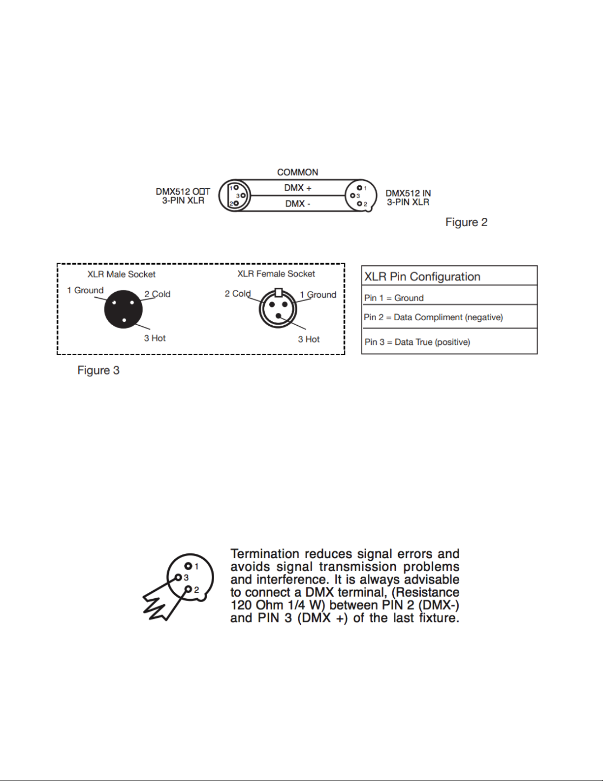
Figure 4
DMX512 IN
3-PIN XLR
NOTICE
Be sure to follow figures two and three when making your own cables. Do not use the ground lug on
the XLR connector. Do not connect the cable’s shield conductor to the ground lug or allow the shield
conductor to come in contact with the XLR’s outer casing. Grounding the shield could cause a short
circuit and erratic behavior.
SPECIAL NOTE: LINE
TERMINATION
When longer runs of cable are used, you may need to use a terminator on the last unit to avoid
erratic behavior. A terminator is a 110-120 ohm 1/4 watt resistor, which is connected between pins 2
and 3 of a male XLR connector (DATA + and DATA -). This unit is inserted in the female XLR
connector of the last unit in your daisy chain to terminate the line. Using a cable terminator (ADJ part
number Z-DMX/T) will decrease the possibilities of erratic behavior.
Page 13
13
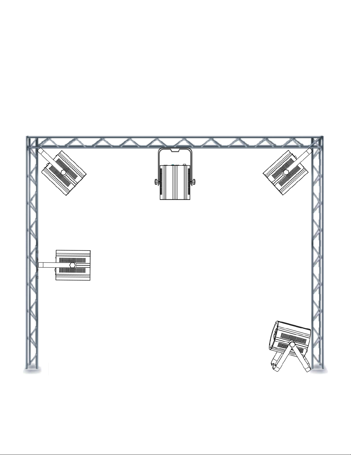
INSTALLATION INSTRUCTIONS
INSTALLATION
This unit should be mounted using a mounting clamp (not provided), affixing it to the mounting
bracket that is provided with the unit. Always ensure that the unit is firmly fixed to avoid vibration
and slipping while operating. Always ensure that the structure to which you are attaching the unit is
secure and is able to support the weight of ten (10) times the unit’s weight and any mounting
accessories. A safety cable (optional) is recommended when installing the fixture. It is also
recommended that a professional installs the equipment and it must be installed in a place where it
is out of the reach of people’s grasp.
Page 14

14
SYSTEM MENU
MODE
manual
SET UP
manual
UP/DOWN
manual
Instruction
DMX
MODE
Address
d.001%~%d.512%
Sets the DMX starting address
Channels
Ch03%
The unit occupies 3 DMX channels
Ch04%
The unit occupies 4 DMX channels
Ch06%
The unit occupies 6 DMX channels
Ch07%
The unit occupies 7 DMX channels
Ch08%
The unit occupies 8 DMX channels
Ch8A%
The unit occupies 8 DMX channels
Ch10%
The unit occupies 10 DMX channels
Ch11%
The unit occupies 11 DMX channels
NO DMX
mode
blAc%
When DMX signal is lost or interrupted, the unit will
default to BLACKOUT option. It will switch all LED’s off
LASt%
When DMX signal is lost or interrupted, the unit will
default to HOLD option. It will hold the last state before
signal was lost.
ProG%
When DMX signal is lost or interrupted, the unit will
default to AUTO. It will run the internal programs.
Delay
mode
dr;0%~%dr;5%
Select the unit delay mode
SLAVE
MODE
Slave
mode
SLAu%
Set the unit into slave mode
DIMMER
MODE
Red
dimmer
r.000%~%r.255%
Adjust the intensity of the red color
Green
dimmer
G.000%~%G.255%
Adjust the intensity of the green color
Blue
dimmer
b.000%~%b.255%
Adjust the intensity of the blue color
Amber
dimmer
A.000%~%A.255%
Adjust the intensity of the amber color
Flash
FS.00%~%FS.15%
Adjust the flash speed, FS.00 is flash off, FS.01 is
slowest, FS.15 is fastest
MODES
The COB Cannon Wash ST has 5 modes: DMX Mode, Manual Dimmer Color Mode, Sound Active
Mode, Auto Run Program Mode and Static Color Select Mode.
During operation, the display will lock after 30 seconds. To unlock the display, press and hold down
the MODE button for 3 seconds to unlock.
Page 15

15
MODE
manual
SET UP
manual
UP/DOWN
manual
Instruction
SOUND
MODE
Mode select
So01%~%So16%
Select the 16 built-in sound modes
Sensitivity
select
SJ;1%~%SJ;8%
Adjust the sensitivity of the sound-active,%SJ;1 is
the lowest level, SJ;8 is the highest level
AUTO
RUN
MODE
Dreaming mode
set
AF01%~%AF16%
Select the 16 built-in dreaming mode
Jumping mode
set
AJ01%~%AJ16%
Select the 16 built-in jumping mode
Auto Dreaming
& Jumping
mode
A;JF%
Set the light in auto dreaming & jumping mode,
the dreaming mode and jumping mode will run
in a continuous cycle
Speed set
Sp.01%~%SP.16%
Adjust the speed of the dreaming/jumping mode
STATIC
COLOR
SELECT
MODE
Color select
CL00%~%CL64%
Select the 64 static colors
Flash
FS.00%~%FS.15%
Adjust the flash speed,%FS.00 is flash off,%FS.01 is
slowest, FS.15 is fastest
OTHER
MODE
Display
don%
LED digital tube display always on
on/off
doff%
LED digital tube display off
IR remote
function
1ron%
IR remote function on
on/off
1rof%
IR remote function off
Display
normal / inverse
Stnd%
LED digital tube display normal
%%%
%
LED digital tube display inversion
Initialization
mode
dEFA%
Initialize the unit at the extra factory setting
%
%
%
%
%
%
!
Page 16

16
DMX$ Mode:$ Operating through a DMX controller gives!the user the freedom to create!their!own
programs tailored to their own individual needs. See pages 18-22 for each mode’s DMX traits.
Press the MODE button to select the DMX mode.
DMX Addressing and Channel Mode: This function will allow you to control each individual
fixture’s traits!with a standard DMX 512 controller.!(When!a!DMX!Address!is!set,!the!LED!display!
will!flicker!if!there!is!no!signal!from!the!controller.)
1.!To run your fixture in DMX mode press the MODE button until “d.XXX” is displayed. “XXX”
represents the current displayed DMX address.
2.!Use the UP or DOWN buttons to select your desired DMX address, then press the SET UP
button to select your DMX Channel mode.
3.!Use the UP or DOWN button to scroll through the DMX Channel modes (Ch03, Ch04, Ch05,
Ch06, Ch07, Ch08, Ch8A, Ch10 and Ch11).
No DMX Setup: This!mode!allows!the!unit!to!default!to!one!of!three!modes!if!the!DMX!signal!is!
lost!or!interrupted.!!
1.!Press!the!SET UP button to select your setting.
2.!Press the UP or DOWN button to select one of the three options.!
BLACKOUT = “blAc”.!The!unit!will!switch!all!LED’s!off!if!signal!is!lost.!
HOLD = “LASt”.!The!unit!will!hold!the!last!state!before!the!signal!was!lost.!
AUTO = “ProG”.!The!unit!will!run!the!default!internal!programs.!
Delay Mode: Select the unit delay mode by pressing the SET UP button until “dr-X” is displayed.
Press the Up or Down button to set the delay rate 0-5.!After you have chosen your desired DMX
Channel mode, plug in the fixture via the XLR connections to any standard DMX controller.!
Slave Mode: Press the MODE button to select the Slave mode.
Slave mode will be displayed as “SLAv”.
Note, while in Slave mode, the SET UP, UP and DOWN buttons will not function.
Manual Dimmer Color Mode: Press the MODE button to select the manual Dimer Color Select
mode. The Color Red will be displayed as “r.XXX” with “XX” representing the dimming rate of 0-255.
1.!Press the SET UP button to select a different color; green “GXXX”, blue “bXXX” or amber “AXXX”.
2.!Press the Up or Down button to set the dimming rate 0-255.
Flash Speed Select: Press MODE button to select the Flash Speed Select mode.
Flash Speed will be displayed as “FS.XX” with “XX” representing the flash speed rate.
1.!Press the SET UP button to adjust the desired flash speed.
2.!Press the Up or Down button to set the speed between “FS.00” (flash off), “FS.01” (slowest flash)
and “FS.15” (fastest flash).
Page 17

17
Sound Active Mode: In this mode the COB Cannon Wash ST will react to sound, and chase
through the different colors. Press MODE button to select the Sound Active mode
Sound Active mode will be displayed as “SoXX” with “XX” representing Sound Active mode (1-8).
1.! Press the SET UP button to adjust the sound sensitivity. “SJ-X” should be displayed.
2.! Press the UP or DOWN button to adjust the sensitivity level from 1 (off) to 8 (highest).
Auto Run Program Mode: There are 3 types of Auto Run Modes to choose from; Color Fade
Color Change, and both modes running together. The running speed is adjustable in all 3 modes.
Press the MODE button until “AFXX”, “AJXX”, or “A-JF” is displayed.
•! Color Fade mode = “AFXX”, there are 16 Color Fade modes to choose from.
Use the UP or DOWN button to scroll through the different Auto Fade modes.
•! Color Change mode = “AJXX”, there are 16 Color Change modes to choose from.
Use the UP or DOWN button to scroll through the different Auto Change modes.
•! Both Color Fade and Color Change modes running = “A-JF
After you have chosen your desired running mode press the SET UP button until “SP.XX” is
displayed. When this is displayed you can adjust the running speed of your desired program. Use
the UP or DOWN button to adjust the speed between “SP.01” (slowest) and “SP.16” (fastest).
Once you have set your desired running speed, press the SET UP button to return to your
desired Auto Run Mode.
Static Color Select Mode: Choose between 64 static colors and activate/deactivate strobe.
1.! Press MODE button to select the Static Color Select mode.
2.! Press the SET UP button until “CLXX” or “FSXX” is displayed.
•! Static Color Mode = “CLXX”. There are 64 static colors to choose from. Use the UP or
DOWN button to select desired static color.
,
•! Flash Speed Select = “FS.XX”. Use the UP or DOWN button to adjust between “FS.00”
(flash off), and “FS.01” (slowest flash) to “FS.15” (fastest flash).
Other Program Select Mode: There are 4 “Other” setup features to adjust. LED Display On/Off,
IR Remote On/Off, Display Inversion and Initialization.
Press the MODE button until “doXX”, “IrXX”, “Stnd” or “dEFA” is displayed.
•! LED Display On/Off = “doXX”. Set the LED display to turn off after 60 seconds by pressing
UP or DOWN button to display “doff”. The display will turn off after 60 seconds and will
reappear with the press of a button. Be advised that it will turn off again automatically after
60 seconds of inactivity. Selecting “don “ will set the LED display to On at all times.
•! IR Remote Function On/OFF = “IrXX”. Press UP or DOWN button to display “Iron” to enable
IR remote function or to “IroF” to disable IR remote function.
•! LED Display Inversion = “Stnd”. Press UP or DOWN button to invert to display 180 degrees.
•! Initialization select mode = “dEFR”. Press the UP and DOWN buttons simultaneously
to restore all modes to default settings. Press the MODE button to exit.
Page 18

18
DMX CHANNELS/VALUES/FUNCTIONS
DMX CHANNELS / VALUES / FUNCTIONS (11 DMX Channels)
SUPPORTS SOFTWARE VERSION ! 1.0
MODE / CHANNEL
VAL UE
FUNCTION
CH03
CH04
CH06
CH07
CH08
CH8A
CH10
CH11
1 9
9
COLOR MACRO S
0
OFF
1-4
Color Macro 01
5-8
Color Macro 02
9-12
Color Macro 03
13-16
Color Macro 04
17-20
Color Macro 05
21-24
Color Macro 06
25-28
Color Macro 07
29-32
Color Macro 08
33-36
Color Macro 09
37-40
Color Macro 10
41-44
Color Macro 11
45-48
Color Macro 12
49-52
Color Macro 13
53-56
Color Macro 14
57-60
Color Macro 15
61-64
Color Macro 16
65-68
Color Macro 17
69-72
Color Macro 18
73-76
Color Macro 19
77-80
Color Macro 20
81-84
Color Macro 21
85-88
Color Macro 22
89-92
Color Macro 23
93-96
Color Macro 24
97-100
Color Macro 25
101-104
Color Macro 26
105-108
Color Macro 27
109-112
Color Macro 28
113-116
Color Macro 29
117-120
Color Macro 30
121-124
Color Macro 31
125-128
Color Macro 32
Page 19

19
DMX CHANNELS / VALUES / FUNCTIONS (11 DMX Channels)
SUPPORTS SOFTWARE VERSION ! 1.0
MODE / CHANNEL
VAL UE
FUNCTION
CH03
CH04
CH06
CH07
CH08
CH8A
CH10
CH11
1 9
9
129-132
Color Macro 33
133-136
Color Macro 34
137-140
Color Macro 35
141-144
Color Macro 36
145-148
Color Macro 37
149-152
Color Macro 38
153-156
Color Macro 39
157-160
Color Macro 40
161-164
Color Macro 41
165-168
Color Macro 42
169-172
Color Macro 43
173-176
Color Macro 44
177-180
Color Macro 45
181-184
Color Macro 46
185-188
Color Macro 47
189-192
Color Macro 48
193-196
Color Macro 49
197-200
Color Macro 50
201-204
Color Macro 51
205-208
Color Macro 52
209-212
Color Macro 53
213-216
Color Macro 54
217-220
Color Macro 55
221-224
Color Macro 56
225-228
Color Macro 57
229-232
Color Macro 58
233-236
Color Macro 59
237-240
Color Macro 60
241-244
Color Macro 61
245-248
Color Macro 62
249-252
Color Macro 63
253-255
Color Macro 64
Page 20

20
DMX CHANNELS / VALUES / FUNCTIONS (11 DMX Channels)
SUPPORTS SOFTWARE VERSION ! 1.0
MODE / CHANNEL
VAL UE
FUNCTION
CH03
CH04
CH06
CH07
CH08
CH8A
CH10
CH11
1 1 1 1 1 1
1
RED
0-255
0-100%
2
RED FINE 16-BIT
0-255
0-100%
2 2 2 2 3 2
2
GREEN
0-255
0-100%
4
GREEN FINE 16-BIT
0-255
0-100%
3 3 3 3 5 3
3
BLUE
0-255
0-100%
6
BLUE FINE 16-BIT
0-255
0-100%
4 4 4 4 7 4
4
AMBER
0-255
0-100%
8
AMBER FINE 16-BIT
0-255
0-100%
2 5 5 5
5
SHUTTER / STROBE
0-31
LED OFF
32-63
LED ON
64-95
Strobe Effect SLOW to FAST
96-127
LED ON
128-159
Strobe Pulse SLOW to FAST
160-191
LED ON
192-223
Random Strobe SLOW to FAST
224-255
LED ON
3 5 6 6 6
6
MASTER DIMMER
0-255
0-100%
6 7 7 7
7
MASTER DIMMER FINE 16-BIT
0-255
0-100%
8
11
DIMMING MODES
0-20
STANDARD
21-40
STAGE
41-60
TV
61-80
ARCHITECTURAL
81-100
THEATER
101-120
STAGE 2
121-255
DEFAULT TO UNIT SETTING
Page 21

21
DMX CHANNELS / VALUES / FUNCTIONS (11 DMX Channels)
SUPPORTS SOFTWARE VERSION ! 1.0
MODE / CHANNEL
VAL UE
FUNCTION
CH03
CH04
CH06
CH07
CH08
CH8A
CH10
CH11
8
8
CH9 MODES
0-51
STANDARD DIM MODE
52-102
ENGAGE CH9 COLOR MACRO MODE
103-153
ENGAGE CH9 COLOR JUMP MODE
154-204
ENGAGE CH9 COLOR DREAM MODE
205-255
ENGAGE CH 9 SOUND MODE
9
9
COLOR JUMP MODE
0-15
Color Jump 1
16-31
Color Jump 2
32-47
Color Jump 3
48-63
Color Jump 4
64-79
Color Jump 5
80-95
Color Jump 6
96-111
Color Jump 7
112-127
Color Jump 8
128-143
Color Jump 9
144-159
Color Jump 10
160-175
Color Jump 11
176-191
Color Jump 12
192-207
Color Jump 13
208-223
Color Jump 14
224-239
Color Jump 15
240-255
Color Jump 16
9
9
COLOR DREAM MODE
0-15
Color Dream 1
16-31
Color Dream 2
32-47
Color Dream 3
48-63
Color Dream 4
64-79
Color Dream 5
80-95
Color Dream 6
96-111
Color Dream 7
112-127
Color Dream 8
128-143
Color Dream 9
144-159
Color Dream 10
160-175
Color Dream 11
176-191
Color Dream 12
192-207
Color Dream 13
208-223
Color Dream 14
224-239
Color Dream 15
240-255
Color Dream 16
Page 22

22
DMX CHANNELS / VALUES / FUNCTIONS (11 DMX Channels)
SUPPORTS SOFTWARE VERSION ! 1.0
MODE / CHANNEL
VAL UE
FUNCTION
CH03
CH04
CH06
CH07
CH08
CH8A
CH10
CH11
9
9
SOUND MODE
0-15
Sound Ac tive 1
16-31
Sound Ac tive 2
32-47
Sound Ac tive 3
48-63
Sound Ac tive 4
64-79
Sound Ac tive 5
80-95
Sound Ac tive 6
96-111
Sound Ac tive 7
112-127
Sound Ac tive 8
128-143
Sound Ac tive 9
144-159
Sound Ac tive 10
160-175
Sound Ac tive 11
176-191
Sound Ac tive 12
192-207
Sound Ac tive 13
208-223
Sound Ac tive 14
224-239
Sound Ac tive 15
240-255
Sound Ac tive 16
10
10
SPEED / SENSIVITY
0-255
COLOR JUMP/DREAM MODES SPEED -SLOW to FAST
0-31
SOUND MODE SENSITIVITY = OFF
32-255
SOUND MODE SENSITIVITY = HIGH to LOW
Dimmer Curve Chart
Page 23

23
REMOTE OPERATING INSTRUCTIONS
Airstream IR (sold separately): The remote transmitter plugs into the headphone jack of your iOS
phone or tablet. To control your IR fixture, you must raise the volume to the maximum on your iOS
phone or tablet and aim the transmitter at the fixture sensor and be no more than 15 feet away.
After you have purchased the Airstream IR transmitter, the app is a free download from the app
store for your iOS phone or tablet. The app comes with 3 pages of control depending on the fixture
you are using. Please see below for the IR Functions in the corresponding app page.
Works with App Page 1.
UC IR Remote: The UC IR Remote can only be used if “IR Remote Function” is set to “On” (see
page 17 for instructions on enabling IR Remote Function).
•! STAND BY - Pressing this button will blackout the fixture. Press
the button again to return to the initial state.
•! FULL ON: Press this button to fully light up the unit.
•! FADE/GOBO: Press this button to switch between Color Fade,
Color Change and Auto Run mode.
•! DIMMER + and DIMMER -: Use the buttons to adjust the color
output intensity when color mode is active.
•! STROBE: Press this button for strobing, then press button ‘1’ to
select slow strobe speed, button ‘2’ to select medium strobe
speed, button ‘3’ to select fast strobe speed, button ‘4’ to select
faster strobe speed.
•! COLOR: Press this button to activate color mode. Use buttons 1-9
to select your desired color.
•! 1-9 BUTTONS: Use buttons 1-4 to select your desired strobe
speed when strobe mode is active. Use buttons 1-9 to select your
desired color when color mode is active or your desired show
when show mode is active.
•! SOUND ON and SOUND OFF: Use the buttons to activate and deactivate sound active mode.
•! SHOW 0: Press this button to select Show mode. Then use buttons 1-9 to select Shows 1-9.
Press the “Show 0” button twice to run Show #10, and press button ‘1’ twice to run show #11.
Page 24

24
Multiple Unit Power Linking
With this feature you can connect the fixtures to one another using the power cable input and output
sockets.
NOTE: USE CAUTION WHEN POWER LINKING OTHER FIXTURES AS THE POWER
CONSUMPTION OF OTHER MODEL FIXTURES MAY EXCEED THE MAX POWER OUTPUT ON
THIS FIXTURE! CHECK SIL SCREEN FOR MAX AMPS.
Master-Slave Setup
1.! Daisy chain your units via the XLR connector on the rear of the unit. Use standard XLR data
cables to link your units together. Remember that the Male XLR connector is the input and
the Female XLR connector is the output. The first unit in the chain (master) will use the
female XLR connector only. The last unit in the chain will use the male XLR connector only.
2.! Set the “Master” unit to your desired mode of operation.
3.! On the “Slave” units press the MODE button until “SLAu” is displayed. Each “Slave” unit
must be set to the same setting.
4.! Connect the first “Slave” unit to the “Master.” The “Slave” unit(s) should now start following
the “Master” unit.
Optional Lens Change
The COB Cannon Wash ST comes with an 80-degree lens already attached. Included in the box are
optional 40 & 50-degree lenses. To switch lenses simply remove the retainer ring located in front of
the current lens. After the retainer ring has been removed carefully remove the lens, and attach
your desired lens. Reinstall the retainer ring and the switch is complete. When reinstalling the
retainer ring, make sure to insert 3 points of the retainer ring into the 3 notches located around the
inside of the lens frame.
Fuse Replacement
Disconnect the unit from its power source. Remove the power cord from the unit. Once the cord
has been removed, the fuse holder is located under the powerCON connection. Use a Phillips
head screwdriver to remove the fuse holder. Remove the fuse located inside the fuse holder and
replace with the new fuse. Install the fuse holder and new fuse and secure it.
Cleaning
Due to fog residue, smoke, and dust cleaning the internal and external optical lenses must be
carried out periodically to optimize light output.
1.! Use normal glass cleaner and a soft cloth to wipe down the outside casing.
2.! Clean the external optics with glass cleaner and a soft cloth every 20 days.
3.! Always be sure to dry all parts completely before plugging the unit back in.
Cleaning frequency depends on the environment in which the fixture operates (i.e. smoke,
fog residue, dust, dew).
Page 25

25
TROUBLE SHOOTING TIPS
Unit does not turn on:
1. Confirm the unit has AC power.
2. Check if circuit breaker that controls the AC outlet the light is plugged into is not tripped.
3. Confirm the AC power cord from the light is not damaged or cut.
4. Check the fuse and see if it needs to be replaced.
5. If none of these solutions work, please contact ADJ Customer Service.
Unit does not respond to DMX:
1. Check that the DMX cables are connected properly and are wired correctly (pin 3 is “hot”; on
some other DMX devices pin 2 may be ‘hot’). Also, check that all cables are connected to the
right connectors; it does matter which way the inputs and outputs are connected.
Unit does not respond to sound:
1. Quiet or high-pitched sounds will not activate the unit.
2. Make sure that Sound Active mode is activated.
F REQUENTLY ASKED QUESTIONS
Listed below are a few answers to common questions users may have.
1. Can you use barn doors with the COB Cannon Wash ST?
Yes, barn doors (BAR001) are an optional accessory and can be purchased separately.
2. What is the light output in lux?
996 LUX @ 2M; 238 LUX @4M (80-degree), 1472 LUX @2M; 373 LUX @4M (50-degree), 1970 LUX
@2M; 474 LUX @4M (40-degree).
3. Is the COB Cannon Wash ST flicker free?
Yes, the COB Cannon Wash ST features Flicker Free operation. At 1,000Hz, there should be no
flickering on camera.
4. How many fixtures can be daisy chained together?
Up to 5 COB Cannon Wash ST units can be daisy chained together. (After 5 fixtures you will need to
use a new power outlet. They must be the same fixtures. DO NOT mix fixtures!) Use caution when
power linking other model fixtures as the power consumption of other model fixtures may exceed
the max power output on this fixture. Check Silk Screen for Max Amps.
Page 26

26
TECHNICAL SPECIFICATIONS
COB Cannon Wash ST
Power Draw:
150W, 1.2A @ 120V/60Hz
148W, 0.7A @ 220V/50Hz
Light Source:
150W!RGBA!4!in!1!COB!LED!source
Volt age:
100V ~ 240V/50~60Hz
Beam Angle:
80 Degrees (Optional 40° & 50° Lenses Included)
Working Position:
Any safe working position
Power Cord Daisy Chain:
5 Fixtures Max.
Fuse:
3 Amp
Colors:
Cool White & RGBA Mixing
DMX Channels:
8 DMX Modes: 3/4/6/7/8 and 8/10/11 Channels
Dimming:
0-100% Electronic Dimming
Strobe Flash Rate (Hz):
0.65Hz – 11Hz
Flicker Free:
Yes , 1,000Hz
IP Rating:
IP20 (Indoor Use Only)
Weight:
9.26 lbs./ 4.2Kgs.
Dimensions: (w/ bracket)
13” (330mm) (L) x 10” (256mm) (W) x 7.5” (190mm) (H)
Dimensions: (w/out bracket)
8.75” (218mm) (L) x 7.5” (190mm) (W) x 7.5” (190mm) (H)
Warranty:
2 Year (730 Days)
Specifications and improvements in the design of this unit / manual subject to change without any prior written notice.
Order Code
Description
AC5PDMX3
3’ DMX cable with 5-pin male to 5-pin female connection.*
AC5PDMX3PRO
Pro Series 3’ DMX cable with 5-pin male to 5-pin female connection.*
S-Cable/60
Safety Cable with 60-pound weight rating
O-CLAMP
360 degree clamp that wraps around truss tubing.
PRO-CLAMP
360 degree aluminum clamp with a max rating of 1100 lbs.
OPTIONAL ACCESSORIES
*Additional lengths available at www.adj.com
Page 27
27
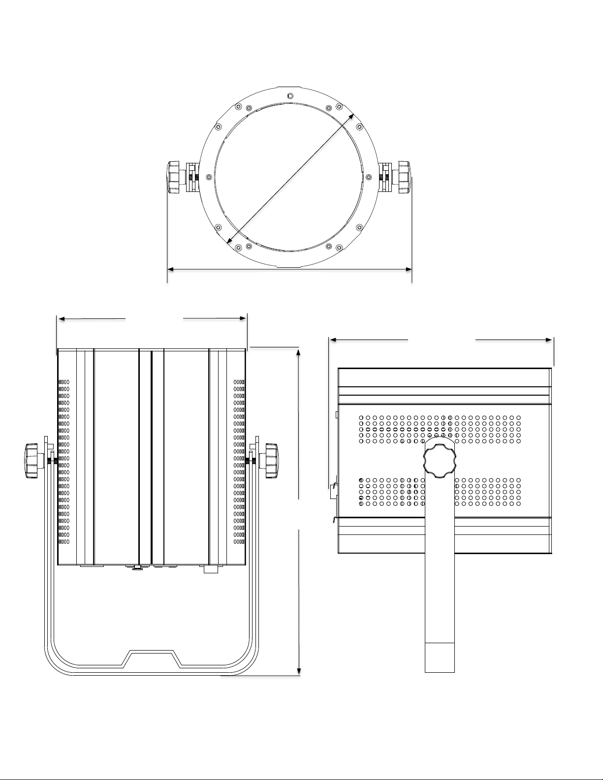
DIMENSIONS
Ø 7.5”
190 mm
8.5”
218.5 mm
Ø 7.5”
190 mm
10”
256 mm
10”
256 mm
 Loading...