


9,67$
9,67$ &1
6HFXULW\ 6\VWHP
,QVWDOODWLRQ DQG 6HWXS *XLGH
 *
*
•• •
• • • •
••
•••
•• •
•••
®
K3892V1 4/00

VISTA-15/VISTA-15CN Installation & Setup Guide
ii

RECOMMENDATIONS FOR PROPER PROTECTION
The Following Recommendations for the location of Fire and Burglary Detection Devices Help Provide Proper Coverage for the Protected Premises.
Recommendations for Smoke and Heat Detectors
With regard to the number and placement of smoke/heat detectors, we subscribe to the recommendations contained in the National Fire Protection Association's (NFPA) Standard #72 noted below.
Early warning fire detection is best achieved by the installation of fire detection equipment in all rooms and areas of the household as follows: For minimum protection, a smoke detector should be installed outside of each separate sleeping area and on each additional floor of a multi-floor family living unit, including basements. The installation of smoke detectors in kitchens, attics (finished or unfinished), or in garages is not normally recommended.
For additional protection, the NFPA recommends that you install heat or smoke detectors in the living room, dining room, bedroom(s), kitchen, hallway(s), attic, furnace room, utility and storage rooms, basements, and attached garages.
In addition, we recommend the following:
•Install a smoke detector inside every bedroom where a smoker sleeps.
•Install a smoke detector inside every bedroom where someone sleeps with the door partly or completely closed. Smoke could be blocked by the closed door. Also, an alarm in the hallway outside may not wake up the sleeper if the door is closed.
•Install a smoke detector inside bedrooms where electrical appliances (such as portable heaters, air conditioners, or humidifiers) are used.
•Install a smoke detector at both ends of a hallway if the hallway is more than 40 feet (12 meters) long.
•Install smoke detectors in any room where an alarm control is located, or in any room where alarm control connections to an AC source or phone lines are made. If detectors are not so located, a fire within the room could prevent the control from reporting a fire or an intrusion.
THIS CONTROL COMPLIES WITH NFPA REQUIREMENTS FOR TEMPORAL PULSE SOUNDING OF FIRE NOTIFICATION APPLIANCES.
|
KITCHEN |
|
|
▲ |
|
|
|
DINING |
▲ |
BEDROOM BEDROOM |
TV ROOM |
KITCHEN |
DINING |
BDRM |
|
|
|
■ |
|
||||
|
|
■ |
|
LIVING ROOM |
BDRM |
||
|
|
|
|
|
|||
|
|
|
■ |
|
|||
|
|
|
|
|
|||
|
|
|
BEDROOM |
|
|
|
|
LIVING ROOM |
BEDROOM |
|
|
|
|
||
|
|
|
|
|
|||
▲■ Smoke Detectors for Minimum Protection
|
|
|
■ |
Smoke Detectors for Additional Protection |
|
|
|
||
|
|
|
▲Heat-Activated Detectors |
|
|
|
|||
|
|
|
BEDROOM |
|
|
|
|
|
|
■ |
|
|
|
BEDROOM |
TO |
BEDROOM |
|
|
BR |
|
|||
|
|
|
|
|
■ |
|
▲ |
|
▲ |
|
|
KTCHN |
. CLOSED |
GARAGE |
LVNG RM |
|
|
||
|
|
|
||
|
|
■ |
DOOR |
|
|
|
|
|
|
BASEMENT |
|
|
|
|
Recommendations for Proper Intrusion Protection
For proper intrusion coverage, sensors should be located at every possible point of entry to a home or commercial premises. This includes skylights and upper windows in a multi-level building.
In addition, we recommend that radio backup be used in a security system so that alarm signals can still be sent to the alarm monitoring station in the event that the telephone lines are out of order (alarm signals are normally sent over the phone lines, if connected to an alarm monitoring station).
iii
Table of Contents
∙ ∙ ∙ ∙ ∙ ∙ ∙ ∙ ∙ ∙ ∙ ∙ ∙ ∙ ∙ ∙ ∙ ∙ ∙ ∙ ∙ ∙ ∙ ∙ ∙ ∙ ∙ ∙ ∙ ∙ ∙ ∙ ∙ ∙ ∙ ∙ ∙ ∙ ∙ ∙ ∙ ∙ ∙ ∙ ∙ ∙ ∙ ∙ ∙ ∙
Conventions Used In This Manual............................................................................................................... |
viii |
SECTION 1. Introduction ............................................................................................................................... |
1–1 |
Description ....................................................................................................................................................... |
1–1 |
Features............................................................................................................................................................ |
1–1 |
SECTION 2. Installing the Control .............................................................................................................. |
2–1 |
Mounting the Cabinet ..................................................................................................................................... |
2–1 |
Installing the Lock (if used) ............................................................................................................................ |
2–1 |
Mounting the Control's Circuit Board Alone in the Cabinet ........................................................................ |
2–2 |
Mounting Control and RF Receiver Circuit Boards Together in the Cabinet ............................................. |
2–3 |
Standard Phone Line Connections ................................................................................................................. |
2–4 |
Wiring the AC Transformer ............................................................................................................................ |
2–5 |
Installing the Backup Battery ........................................................................................................................ |
2–6 |
Earth Ground Connections ............................................................................................................................. |
2–6 |
SECTION 3. Installing Remote Keypads..................................................................................................... |
3–1 |
Keypads That May Be Used............................................................................................................................ |
3–1 |
Wiring to the Keypads..................................................................................................................................... |
3–1 |
Mounting the Keypads .................................................................................................................................... |
3–2 |
Supplementary Power for Additional Keypads ............................................................................................. |
3–2 |
Preliminary Checkout Procedure ................................................................................................................... |
3–3 |
SECTION 4. Basic Hardwired Zones 1–6 .................................................................................................... |
4–1 |
Installing the Hardwired Zones...................................................................................................................... |
4–1 |
Programming Hardwired Zones ..................................................................................................................... |
4–4 |
Checkout Procedure for Hardwired Zones ..................................................................................................... |
4–4 |
SECTION 5. Wired Zone Expansion............................................................................................................. |
5–1 |
Installing Zone Expansion Units .................................................................................................................... |
5–1 |
Connections and Setup.................................................................................................................................... |
5–1 |
Programming Wired Expansion Zones........................................................................................................... |
5–3 |
Checkout Procedure for Wired Expansion Zones .......................................................................................... |
5–3 |
SECTION 6. Wireless Expansion (5800 System)........................................................................................ |
6–1 |
About Wireless Expansion .............................................................................................................................. |
6–1 |
Installing the 5881/5882 Receiver .................................................................................................................. |
6–2 |
Installing the 5800TM Module ....................................................................................................................... |
6–3 |
Jam Detection and Reporting ......................................................................................................................... |
6–3 |
About 5800 Series Transmitters ..................................................................................................................... |
6–3 |
Installing 5800 Series Transmitters............................................................................................................... |
6–7 |
SECTION 7. Relay Outputs & Powerline Carrier Devices ..................................................................... |
7–1 |
About Relays and Powerline Carrier Devices................................................................................................ |
7–1 |
4204 and 4229 Relay Modules ........................................................................................................................ |
7–1 |
Powerline Carrier Devices .............................................................................................................................. |
7–3 |
Programming Relay Outputs .......................................................................................................................... |
7–4 |
SECTION 8. 4285 & 4286 VIP Module .......................................................................................................... |
8–1 |
About the 4285 & 4286 VIP (Voice Interactive Phone) Module.................................................................... |
8–1 |
Installing the VIP Module............................................................................................................................... |
8–1 |
Programming the 4285/4286 VIP Module...................................................................................................... |
8–4 |
Checking 4285/4286 VIP Module Operation.................................................................................................. |
8–4 |
SECTION 9. External Sounders .................................................................................................................... |
9–1 |
Compatible Sounders....................................................................................................................................... |
9–1 |
NFPA Requirements........................................................................................................................................ |
9–1 |
Sounder Connections and Power .................................................................................................................... |
9–2 |
Sounder Supervision ....................................................................................................................................... |
9–2 |
Testing the Sounder ........................................................................................................................................ |
9–2 |
|
|
|
|
iv
|
Table of Contents |
SECTION 10. Long Range Radio ................................................................................................................ |
10–1 |
About Long Range Radio............................................................................................................................... |
10–1 |
Wiring Connections ....................................................................................................................................... |
10–1 |
Dynamic Signaling Feature .......................................................................................................................... |
10–2 |
SECTION 11. Audio Alarm Verification (AAV) Unit .............................................................................. |
11–1 |
About Audio Alarm Verification ................................................................................................................... |
11–1 |
Wiring Connections ....................................................................................................................................... |
11–1 |
SECTION 12. Final Power-Up ..................................................................................................................... |
12–1 |
Earth Ground Connections ........................................................................................................................... |
12–1 |
AC Power-Up ................................................................................................................................................. |
12–1 |
Connecting the Backup Battery.................................................................................................................... |
12–1 |
Battery Tests.................................................................................................................................................. |
12–2 |
SECTION 13. Mechanics of Programming ............................................................................................... |
13–1 |
About Programming ...................................................................................................................................... |
13–1 |
Entering Program Mode................................................................................................................................ |
13–2 |
Programming a Data Field............................................................................................................................ |
13–2 |
Reviewing a Data Field/Erasing an Entry ................................................................................................... |
13–2 |
Interactive Mode Programming ( 56, 58, 80, 81, and 82)................................................................ |
13–2 |
Loading Factory Defaults.............................................................................................................................. |
13–3 |
Programming System Setup Fields .............................................................................................................. |
13–3 |
Exiting the Programming Mode ................................................................................................................... |
13–3 |
SECTION 14. Zone Response Type Definitions....................................................................................... |
14–1 |
Zone Type Definitions.................................................................................................................................... |
14–1 |
SECTION 15. Data Field Descriptions....................................................................................................... |
15–1 |
Descriptions of System Data Fields.............................................................................................................. |
15–1 |
SECTION 16. Zone Programming............................................................................................................... |
16–1 |
About Zone Programming ............................................................................................................................. |
16–1 |
56 Zone Programming Procedures............................................................................................................. |
16–1 |
58 Expert Programming Mode Procedures ............................................................................................... |
16–4 |
To Remove a Zone.......................................................................................................................................... |
16–6 |
To Delete and Replace a Transmitter Serial Number................................................................................. |
16–7 |
To Enter and Duplicate Wireless Keys ........................................................................................................ |
16–7 |
SECTION 17. Output Device Programming............................................................................................. |
17–1 |
Programming Options Defined ..................................................................................................................... |
17–1 |
Programming Output Relays and Powerline Carrier Devices.................................................................... |
17–3 |
SECTION 18. Zone Lists................................................................................................................................ |
18–1 |
About Zone List Menu Mode ......................................................................................................................... |
18–1 |
Zone List Displays ......................................................................................................................................... |
18–1 |
Cross Zoning - Zone List 04........................................................................................................................... |
18–2 |
NIGHT-STAY - Zone List 05......................................................................................................................... |
18–2 |
SECTION 19. Alpha Descriptor Programming........................................................................................ |
19–1 |
About Alpha Descriptor Programming......................................................................................................... |
19–1 |
Zone Descriptors ............................................................................................................................................ |
19–1 |
Programming Zone Descriptors (Program Menu Mode 82) ..................................................................... |
19–1 |
Adding Custom Words/Numbers (not annunciated by the 4285/4286 VIP Module) ................................. |
19–3 |
SECTION 20. Remote Programming and Control (Downloading) ..................................................... |
20–1 |
About Remote Programming......................................................................................................................... |
20–1 |
Equipment Required ..................................................................................................................................... |
20–1 |
Initial Download ............................................................................................................................................ |
20–2 |
Remote Programming Commands................................................................................................................ |
20–2 |
Remote Programming Advisory Notes ......................................................................................................... |
20–2 |
SECTION 21. System Communication....................................................................................................... |
21–1 |
Panel Communication with Central Station................................................................................................ |
21–1 |
Report Code Formats..................................................................................................................................... |
21–1 |
|
|
|
|
v

VISTA-15/VISTA-15CN Installation & Setup Guide
SECTION 22. System Operation ................................................................................................................. |
22–1 |
Security Codes ............................................................................................................................................... |
22–1 |
Keypad Functions .......................................................................................................................................... |
22–2 |
Setting the Real-Time Clock ......................................................................................................................... |
22–6 |
SECTION 23. |
Testing the System ............................................................................................................... |
23–1 |
Test Procedure ............................................................................................................................................... |
23–1 |
|
SECTION 24. |
Troubleshooting Guide........................................................................................................ |
24–1 |
SECTION 25. |
Specifications & Accessories.............................................................................................. |
25–1 |
Specifications ................................................................................................................................................. |
25–1 |
|
Accessories (Compatible Devices) ................................................................................................................. |
25–3 |
|
APPENDIX A 5800 RF System Wireless Transmitters............................................................................ |
A–1 |
|
Transmitter Input Loop Identification.......................................................................................................... |
A–1 |
|
APPENDIX B Regulatory Agency Statements.......................................................................................... |
B–1 |
|
APPENDIX C Warnings and Limitations .................................................................................................. |
C–1 |
|
Index............................................................................................................................................................. |
|
Index-1 |
Programming Form .................................................................................................................................... |
Insert |
|
vi

List of Figures
∙ ∙ ∙ ∙ ∙ ∙ ∙ ∙ ∙ ∙ ∙ ∙ ∙ ∙ ∙ ∙ ∙ ∙ ∙ ∙ ∙ ∙ ∙ ∙ ∙ ∙ ∙ ∙ ∙ ∙ ∙ ∙ ∙ ∙ ∙ ∙ ∙ ∙ ∙ ∙ ∙ ∙ ∙ ∙ ∙ ∙ ∙ ∙ ∙ ∙
Figure 1. Installing the Cabinet Lock.................................................................................................................. |
2–1 |
Figure 2. Mounting the PC Board........................................................................................................................ |
2–2 |
Figure 3. Mounting the PC Board and RF Receiver Together in the Cabinet.................................................. |
2–3 |
Figure 4. Telephone Line Connections ................................................................................................................ |
2–4 |
Figure 5. Connections of 4300 Transformer to the Control Board .................................................................... |
2–5 |
Figure 6. Keypad Connections to the Control Board.......................................................................................... |
3–2 |
Figure 7. Using a Supplementary Power Supply for Keypads .......................................................................... |
3–3 |
Figure 8. 2-Wire Smoke Detector Connected to Zone 1...................................................................................... |
4–2 |
Figure 9. 4-Wire Smoke Detector Connections (Zones 2–6) ............................................................................... |
4–3 |
Figure 10. Wiring Connections - 4219 Expansion Module ................................................................................. |
5–2 |
Figure 11. Wiring Connections - 4229 Expansion/Relay Module....................................................................... |
5–2 |
Figure 12. 5881/5882 RF Receiver (cover removed)............................................................................................ |
6–2 |
Figure 13. 4229 Connections to Control .............................................................................................................. |
7–2 |
Figure 14. 4204 Connections to Control .............................................................................................................. |
7–3 |
Figure 15. 4300 Transformer Wiring Connections ............................................................................................. |
7–4 |
Figure 16. 4285/4286 VIP Module Wiring Connections ..................................................................................... |
8–3 |
Figure 17. Typical Sounder Wiring...................................................................................................................... |
9–2 |
Figure 18. Bell Supervision Wiring ..................................................................................................................... |
9–2 |
Figure 19. Long Range Radio Connections ....................................................................................................... |
10–1 |
Figure 20. Connection of AAV Unit When Not Using a 4285/4286 VIP Module ............................................ |
11–2 |
Figure 21. Connection of AAV Unit When Also Using a 4285 or 4286 VIP Module....................................... |
11–2 |
Figure 22. VISTA-15/VISTA-15CN Summary of Connections.................................................. |
Inside Back Cover |
vii

Conventions Used In This Manual
∙ ∙ ∙ ∙ ∙ ∙ ∙ ∙ ∙ ∙ ∙ ∙ ∙ ∙ ∙ ∙ ∙ ∙ ∙ ∙ ∙ ∙ ∙ ∙ ∙ ∙ ∙ ∙ ∙ ∙ ∙ ∙ ∙ ∙ ∙ ∙ ∙ ∙ ∙ ∙ ∙ ∙ ∙ ∙ ∙ ∙ ∙ ∙ ∙ ∙
Before you begin using this manual, it is important that you understand the meaning of the following symbols:
UL |
A UL note that includes specific information that must be followed if you are installing this system |
in a UL Listed application. |
A note that includes specific information that must be followed if you are installing this system in a Canadian UL Listed application..
A checked note includes information you should be aware of before continuing with the installation, and which, if not observed, could result in operational difficulties.
This symbol warns of conditions that could seriously affect the operation of the system, or cause damage to the system. Please read each warning carefully. This symbol also denotes warnings about physical harm to the user.
Enter Zone Num.
(00 = Quit)
00
You may program many system options by responding to alpha keypad display prompts. These prompts are shown in a double-line box.
When programming the system, data fields are indicated by a “star” ( ) followed by the data field number.
PRODUCT MODEL NUMBERS: Unless noted otherwise, references to specific model numbers represent ADEMCO products.
viii

S E C T I O N 1
|
|
|
|
|
|
|
|
|
|
|
Introduction |
∙ |
∙ |
∙ |
∙ |
∙ |
∙ |
∙ ∙ ∙ ∙ ∙ ∙ ∙ ∙ ∙ ∙ ∙ ∙ ∙ ∙ ∙ ∙ ∙ ∙ ∙ ∙ ∙ ∙ ∙ |
∙ |
∙ |
∙ |
∙ ∙ ∙ ∙ ∙ ∙ ∙ ∙ ∙ ∙ ∙ ∙ ∙ ∙ ∙ ∙ ∙ |
|
In This Section |
|
|
|
|
|
||||||
♦ Description |
♦ Features |
||||||||||
∙ |
∙ |
∙ |
∙ |
∙ |
∙ |
∙ ∙ ∙ ∙ ∙ ∙ ∙ ∙ ∙ ∙ ∙ ∙ ∙ ∙ ∙ ∙ ∙ ∙ ∙ ∙ ∙ ∙ ∙ |
∙ |
∙ |
∙ |
∙ ∙ ∙ ∙ ∙ ∙ ∙ ∙ ∙ ∙ ∙ ∙ ∙ ∙ ∙ ∙ ∙ |
|
Description
The VISTA-15/VISTA-15CN is a security system control that supports up to 32 zones, including six basic hardwired zones (1 through 6) and a maximum of 26 expansion zones. These expansion zones may include up to eight hardwired zones, or up to 26 wireless zones if hardwired zones are not used. Three separate keypad-activated zones are also provided.
Features
Basic Hardwired Zones
Provides 6 basic hardwired zones having the following characteristics:
•EOLR supervision supporting N.O. or N.C. sensors
•Programmable response time (10, 350, or 700 milliseconds)
•Up to sixteen 2-wire smoke detectors on zone 1
•4-wire smoke or heat detectors on zones 2 through 6 (as many as can be powered from Auxiliary Power on the control).
Optional Expansion Zones (26 total: up to 8 wired with 18 wireless, OR 26 wireless)
Wired Expansion:
Supports up to 8 additional wired zones using a 4219 Expansion Module or 4229
Expansion/Relay Module. These zones have the following characteristics:
•EOLR supervision supporting N.O. or N.C. sensors
•300-500mSec normal response with an option for fast (10-15mSec) response on loop A (first expansion zone).
Wireless Expansion:
Supports up to 26 wireless zones (fewer if using wired expansion zones).
• Requires the use of a 5881 (5882 in Canada) type RF receiver, as indicated below:
Receiver Model |
No. of Zones |
5881L/5882L |
Up to 8 |
5881M/5882M |
Up to 16 |
5881H/5882H |
Up to 26 |
• Requires the use of 5800 Series Wireless Transmitters.
Remote Keypads
Up to 4 of any of the following keypads may be used in the installation:
Fixed-word keypad: |
6128, 6128RF |
Alpha keypad: |
6139 (2-line alphanumeric display) |
1–1

VISTA-15/VISTA-15CN Installation and Setup Guide
Security Codes Supported
•One Installer code for entire system (user 1)
•One Master code for entire system (user 2)
•12 Secondary User codes (users 3–14)
•One Temporary code (user 15)
•One Duress code (user 16).
Temporary Code: A special code that can be used to disarm and arm the system until the Master code is entered.
Duress Code: An emergency code that, when entered by any user to disarm or arm the system, sends a silent duress message to the Central Station.
Keypad Panic Features
•Up to 3 programmable panic key functions provided
•Designated as zones 95, 96, 99
•Activated by wired and wireless keypads
•Distinguished by subscriber ID number.
Zone Monitor Features
•Provides automatic high loop resistance detection on hardwired zones 2–6, and displays a CHECK message for the affected zone when the system is in the disarmed state.
•Contains a Hardwire Short Detection circuit for zones 1-6†, and enabled in 30. Detecting a short in any wired zone, it sends a sensor Trouble message to the Central Station when the system is in the disarmed state. At the same time a CHECK message is displayed on the keypad.
† Hardwire Short Detection is disabled on any zone programmed for FIRE (Zone type 09).
Either condition (high resistance or short) detected on any zone, prevents the system from being armed until the offending condition is cleared. Conversely, when the system is armed, and these conditions occur, an alarm is generated.
Exit Error False Alarm Prevention Features
•Enables the system to determine the difference between an actual alarm and an alarm caused by leaving an entry/exit or interior zone open after the Exit Delay expires. If not disarmed in time, an alarm sounds and an Exit Error report is sent to the Central Station. An exit alarm condition also occurs if an entry/exit or interior zone re-opens within 2 minutes after the end of an Exit Delay.
•The system provides an automatic Exit Delay Reset feature that allows the user to exit (fault), close the door (restore the fault), then re-enter (fault again) the premises within the exit delay time period. Upon re-entering, a new exit delay time period is begun with the keypad annunciating three rapid beeps. This feature only resets the exit delay time once for each arming session.
Optional Output Relays and Powerline Carrier Devices (X10 type)
The VISTA-15/VISTA-15CN supports the following optional output relays and Powerline Carrier devices (X10 type):
•Maximum of 4 output devices
•Up to 4 relays using one 4204 Relay Module
•Up to 2 relays using one 4229 Zone/Relay Module
•Up to 4 Powerline Carrier devices (you must subtract the number of relay outputs actually
used by the 4204 or 4229 modules, if used).
Actions are programmable to respond to zone activity or manual keypad entries.
Powerline Carrier devices require the use of the optional 4300 Transformer Module instead of the supplied 1321/1321CN AC Transformer.
1–2
Section 1 - Introduction
Optional VIP Module
The VISTA-15/VISTA-15CN supports the ADEMCO 4285/4286 VIP Module (refer to
Section 8: 4285/4286 VIP Module for further information).
Provides access to the system via on-premises or off-premises phones for arming, disarming, etc., plus control of relay outputs and Powerline Carrier devices.
Paging Feature
If programmed, the paging feature allows certain system conditions to be reported to a pager. Up to 16 digits may be programmed to be sent as a message to the pager. A 7-digit code following the programmed message indicates the type of condition that has occurred.
Audio Alarm Verification (AAV) Option
Provides a programmable Audio Alarm Verification (AAV) option, which can be used in conjunction with an output relay to permit voice dialog between an operator at the Central Station and a person at the premises.
This AAV option must be used with a relay unit, such as an Eagle Model 1250.
UL |
The AAV option may not be used in UL installations. |
|
Optional Long Range Radio
Allows all messages that have been programmed to go to the primary telephone number to also be sent to any ECP-operational radio (such as the 7835C, 7720PLUS, and 7820) for transmission to the Central Station.
Built-in Telephone Line Monitoring Option
You can monitor telephone line voltage to supervise the phone line connection. You must connect the panel to a proper earth ground or you will get a false line cut indication if this feature is enabled.
The loss of the line can optionally cause a local display, or a display and trouble sound.
Event Logging
Keeps a record of up to 48 selected events in a history log. All control and readout from the log is done via ADEMCO COMPASS software only.
Quick Arm Feature
Quick Arm may be programmed , allowing use of the [#] key in place of the security code for arming (Quick Arm will not work unless the Master code has been programmed into the system).
Alarm Output Features
•Provides a 12VDC, 2 amp output that can drive the compatible sounders listed in Section 9: External Sounders (assuming a fully charged battery is connected).
•Steady output for burglary/panic, or temporal pulse output (3 pulses – pause – 3 pulses – pause – 3 pulses . . .) for fire.
•Uses current-limiting circuitry for protection.
•Provision for Bell supervision.
Optional Bell Supervision
Red jumper on control board, when cut, provides supervision of bell wiring (when bell is wired with EOL resistor, as indicated in the instructions).
1–3

VISTA-15/VISTA-15CN Installation and Setup Guide
Chime/Chime by Zone
Chime, when on, normally sounds when any entry/exit or perimeter zone is faulted. However, a “chime by zone” option, when programmed, allows only specific zones to chime if they are faulted when the system is in the chime mode.
Auxiliary Power Output Features
•Provides 12VDC, 600mA maximum (500mA maximum for UL installations). Uses currentlimiting circuitry for protection.
•Interrupts for smoke detector reset if 4-wire smoke detectors are used.
Programming
Programmed options are stored in electrically erasable, nonvolatile EEPROM memory (information can be reprogrammed at any time and will not be lost in the event of a power loss).
The system can be uploaded, downloaded, or controlled via an IBM-compatible computer, COMPASS software, and a modem specified by ADEMCO.
Keypad programming consists of:
•Data field programming
•Interactive (menu) mode programming.
To program from a keypad, you must connect a 6139 2-line alpha keypad, but it need not stay in the system.
Communication Formats Supported
•ADEMCO Low Speed (Standard or Expanded)
•Sescoa/Radionics (Standard or Expanded)
•ADEMCO Express
•ADEMCO Contact ID
Zone Descriptors
You can assign alpha descriptors to all zones (only when using alpha keypads).
AC Power Supply
Uses 1321/1321CN, 110VAC plug-in transformer with 16.5VAC, 25VA output, unless Powerline Carrier devices (for example, X10 type) are used, in which case a 4300 Transformer Module must be used.
Backup Battery
Rechargeable (Sealed Lead Acid) 12VDC, 4AH-17.2AH. Refer to Section 12: Final PowerUp to calculate the actual battery size needed.
1–4

S E C T I O N 2
Installing the Control
∙ ∙ ∙ ∙ ∙ ∙ ∙ ∙ ∙ ∙ ∙ ∙ ∙ ∙ ∙ ∙ ∙ ∙ ∙ ∙ ∙ ∙ ∙ ∙ ∙ ∙ ∙ ∙ ∙ ∙ ∙ ∙ ∙ ∙ ∙ ∙ ∙ ∙ ∙ ∙ ∙ ∙ ∙ ∙ ∙ ∙ ∙ ∙ ∙ ∙
In This Section
♦ Mounting the Cabinet |
♦ Standard Phone Line Connections |
♦ Installing the Lock |
♦ Wiring the AC Transformer |
♦ Mounting the Control's Circuit Board Alone in |
♦ Installing the Backup Battery |
the Cabinet |
♦ Earth Ground Connections |
|
|
♦ Mounting the Control and RF Receiver Circuit |
|
Boards Together |
|
∙ ∙ ∙ ∙ ∙ ∙ ∙ ∙ ∙ ∙ ∙ ∙ ∙ ∙ ∙ ∙ ∙ ∙ ∙ ∙ ∙ ∙ ∙ ∙ ∙ ∙ ∙ ∙ ∙ ∙ ∙ ∙ ∙ ∙ ∙ ∙ ∙ ∙ ∙ ∙ ∙ ∙ ∙ ∙ ∙ ∙ ∙ ∙ ∙ ∙
Mounting the Cabinet
Use fasteners or anchors (not supplied) to mount the control cabinet to a sturdy wall in a clean, dry area that is not readily accessible to the general public. Four mounting holes are provided at the back of the cabinet.
If an RF receiver is being used and you intend to mount its PC board within the cabinet, note the following:
•Do not mount the cabinet on or near metal objects. This decreases RF range and/or block RF transmissions from wireless transmitters.
•Do not locate the cabinet in an area of high RF interference (revealed by frequent or prolonged lighting of the LED in the receiver after it is operational (random flicker is OK).
Installing the Lock (if used)
Use an ADEMCO No. N6277 Cam Lock and No. N6277–1 Push-On Clip (Retainer Clip). NOTE:The cabinet can be closed and secured without a lock by using 2 screws in the cover's edge.
To install the lock, perform the following steps:
1.Remove the cabinet door. It is easily removed for servicing and is easily reinstalled.
2.Remove the lock knockout from the control cabinet door. Insert the key into the lock. Position the lock in the hole, making certain that the latch will make contact with the latch bracket when the door is closed.
3.Hold the lock steady and insert the retainer clip into the retainer slots. Position the clip as illustrated in order to permit easy removal.
|
RETAINER CLIP |
|
(NOTE POSITION) |
LOCKED |
RETAINER |
|
|
RETAINER |
SLOTS |
|
|
UNLOCKED |
|
CABINET DOOR BOTTOM |
|
Figure 1. Installing the Cabinet Lock
2–1
VISTA-15/VISTA-15CN Installation and Setup Guide
Before installing the cabinet's contents, remove the metal cabinet knockouts required for wiring entry. Do not attempt to remove the knockouts after the circuit board has been installed.
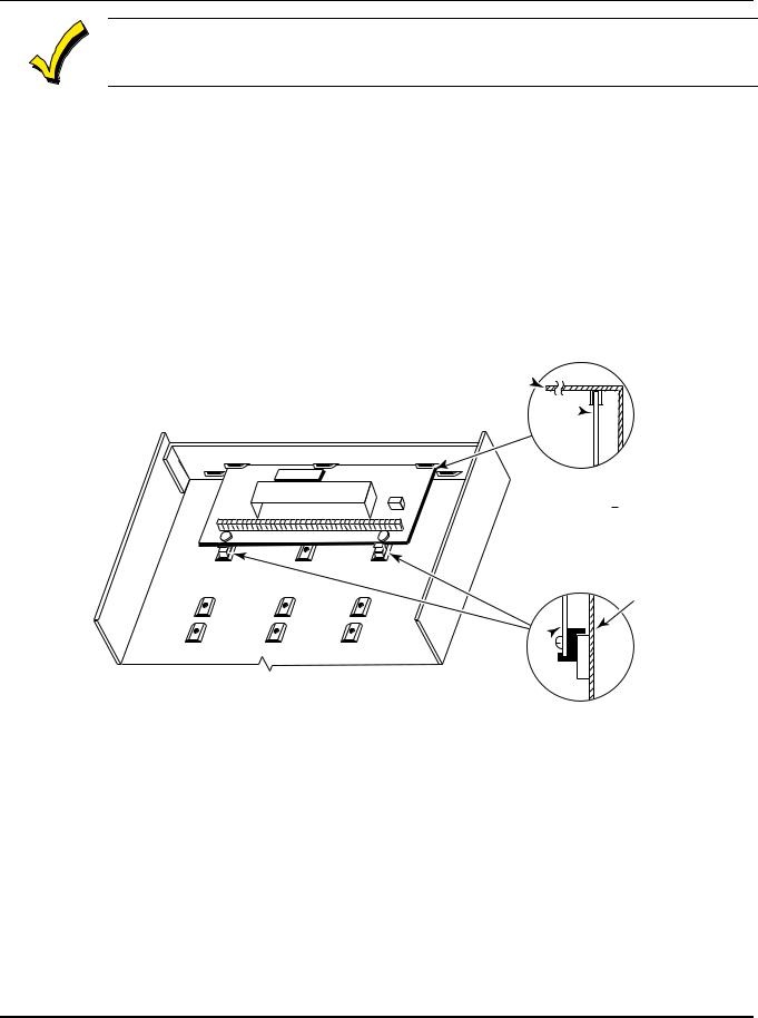
Mounting the Control's Circuit Board Alone in the Cabinet
To mount the circuit board alone in the cabinet, follow these steps:
1.Hang two short mounting clips (provided) on the raised cabinet tabs (see Detail B in Figure 2).
2.Insert the top of the circuit board into the slots at the top of the cabinet. Make sure that the board rests on the correct row (see Detail A).
3.Swing the base of the board into the mounting clips and secure the board to the cabinet with the accompanying screws (see Detail B).
CABINET
CIRCUIT BOARD 
|
|
DETAIL A |
|
|
SIDE VIEW |
|
|
OF BOARD |
+ |
+ |
SUPPORTING |
SLOTS |
CABINET
CIRCUIT 
BOARD
DETAIL B
SIDE VIEW
OF MOUNTING
CLIPS
V15-01-V0
Figure 2. Mounting the PC Board
2–2
Section 2 - Installing the Control
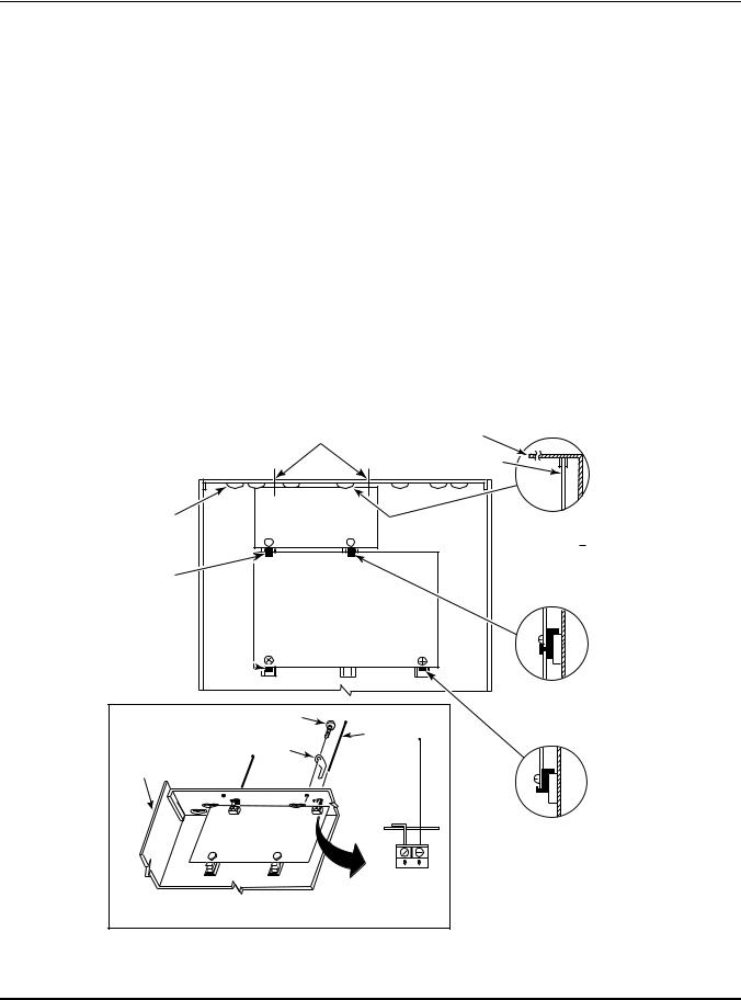
Mounting Control and RF Receiver Circuit Boards Together in the Cabinet
To mount the control and RF receiver boards together in the cabinet, do the following:
1.Hang two short (black) mounting clips (provided with receiver) on the raised cabinet tabs, as shown in Detail B in Figure 3.
2.Insert the top of the receiver board (removed from its own case as described in its instructions) into the slots at the top of the cabinet, as shown in Detail A in Figure 3. Make sure that the board rests on the correct row of tabs, as shown.
3.Swing the base of the board into the mounting clips and secure it to the cabinet with the accompanying screws (see Detail B).
4.Insert the top of the control's board into the slot in the clips and position two long (red) clips at the lower edge of the board (see Detail C).
5.Swing this board into place and secure it with two additional screws.
6.Insert grounding lugs (supplied with the receiver) through the top of the cabinet into the left-hand terminals of the antenna blocks (at the upper edge of the receiver board). Secure the grounding lugs to the cabinet top with the screws provided, as shown in Detail D.
7.Insert the receiver's antennas through the top of the cabinet, into the blocks' right-hand terminals, and tighten the screws.
8.Refer to Section 6: Wireless Expansion (5800 System) for receiver setup and wiring instructions.
|
HOLES FOR ANTENNAS |
|
|
|
AND GROUNDING LUGS |
CABINET |
|
|
|
|
CIRCUIT BOARD |
BOARD |
|
|
|
SUPPORTING |
RECEIVER CIRCUIT BOARD |
DETAIL A |
|
SLOTS |
|
(See Detail D) |
|
|
SIDE VIEW |
||
|
+ |
+ |
|
|
OF BOARD |
||
|
|
|
|
|
|
|
SUPPORTING SLOTS |
MOUNTING |
|
|
|
CLIP |
|
|
|
CONTROL
CIRCUIT
BOARD
MOUNTING
CLIP 
|
|
DETAIL B |
|
|
SIDE VIEW |
SCREW |
|
OF MOUNTING |
(2) |
ANTENNA |
CLIP |
GROUNDING |
(2) |
|
|
|
|
LUG |
|
|
(2) |
|
|
CABINET
|
RCVR BRD |
DETAIL C |
|
|
SIDE VIEW |
||
|
|
||
+ |
+ |
OF MOUNTING |
|
CLIP |
|||
|
|
ANTENNA
MOUNT
(2 PLACES)
DETAIL D
ANTENNA AND GROUNDING LUG INSTALLATION
V15-02-V0
Figure 3. Mounting the PC Board and RF Receiver Together in the Cabinet
2–3
VISTA-15/VISTA-15CN Installation and Setup Guide
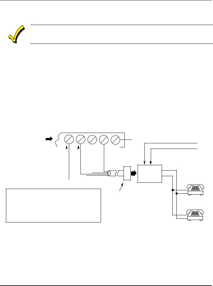
Standard Phone Line Connections
The wiring connections shown here are not applicable if the 4285/4286 VIP Module is used. Refer to Section 8: 4285/4286 VIP Module for information regarding phone line connections, which are different than those shown here.
Connect incoming phone line and handset wiring to the main terminal block via an RJ31X jack (CA38A jack in Canada) as follows and as shown in Figure 4.
Term. 21: Local Handset (TIP – Brown*)
Term. 22: Local Handset (RING – Gray*)
Term. 23: Incoming Phone Line (TIP – Green*)
Term. 24: Incoming Phone Line (RING – Red*)
* Colors of wires in Direct Connect Cord.
Incoming
Handset Telecom Line
{ {
GROUND
21 22 23 24 25
TERMINALS
ON CONTROL
|
|
|
|
|
GREEN (TIP) |
RED (RING) |
|
|
|
|
|||||
|
|
|
|
||||
BROWN (TIP) |
GREY (RING) |
|
|||||
|
|
||||||
|
|
|
|||||
|
|
|
|
|
|
|
|
IMPORTANT!
IF THE PANEL IS NOT CONNECTED TO A PROPER EARTH GROUND, YOU MAY GET FALSE TELEPHONE LINE CUT INDICATIONS (IF THE TELEPHONE LINE MONITOR HAS BEEN PROGRAMMED IN FIELD 92).
|
EARTH GROUND |
|
|
|
INCOMING TELECOM LINE |
||
DIRECT |
TIP RING |
|
|
CONNECT |
|
TIP |
|
CORD |
RJ31X JACK |
PREMISES |
|
|
(CA38A in |
RING |
|
|
PHONES |
||
|
CANADA) |
|
|
|
|
|
|
PLUG |
|
|
|
Figure 4. Telephone Line Connections
2–4

Section 2 - Installing the Control
Wiring the AC Transformer
1321/1321CN Transformer
Wire the 1321/1321CN Transformer to terminals 1 and 2 on the control board. See wiring table below to determine wire gauge.
Use caution when wiring the transformer to the control panel to guard against blowing the fuse inside the transformer (the fuse is nonreplaceable).
4300 Transformer
If you are going to use a 4300 Transformer Interface (required if Powerline Carrier devices are used), connect the 4300 Transformer’s terminals as follows:
1.Connect terminals 1, 3 (AC), and 2 (Ground) to control board terminals 1, 2, and 25, respectively (see Figure 5). See table below to determine wire gauge to use.
WIRING TABLE
Distance of Transformer |
Wire Gauge |
From the Control Panel |
to Use |
Up to 50 feet |
# 20 |
50-100 feet |
# 18 |
100-250 feet |
# 16 |
Wiring to the AC transformer must not exceed 250 feet using 16-gauge wire. The voltage reading between terminals 1 and 2 of the control must not fall below 16.5VAC, or an AC LOSS message is displayed.
Do not plug the transformer into the AC outlet until you are instructed to do so later in the manual.
2.Wire the other three terminals (Sync, Data, Com) on the 4300 Transformer. Wires from these terminals must be connected to a 9-pin connector on the control board (using a 4142TR Cable supplied with the 4300 Transformer), as shown in Figure 5. These particular wires can be 24-gauge or larger, and can be run along with the AC and ground wires to the control panel.
4300 TRANSFORMER/INTERFACE |
|
|
|
|
|
|
|
|
|
|
|||||
|
|
|
|
|
|
1 |
2 |
3 |
4 |
5 |
6 |
7 |
8 |
9 |
9-PIN CONNECTOR |
|
|
|
|
|
|
|
|
|
|
|
|
|
|
|
ON CONTROL BOARD |
|
Earth |
|
|
|
|
VIOLET |
GRAY |
YELLOW |
WHITE |
RED |
GREEN |
BROWN |
BLUE |
BLACK |
|
AC Ground AC |
SyncData Com |
|
|||||||||||||
1 |
2 |
3 |
4 |
5 |
6 |
|
|||||||||
|
|
|
|
|
|
|
|
|
|
||||||
|
|
|
|
|
|
|
|
|
|
|
|
|
|
4142TR CABLE |
|
1 |
25 |
2 |
|
|
|
|
|
|
|
|
|
|
|
|
|
TERMINALS |
|
|
|
|
|
|
|
|
|
|
|
|
|
||
ON CONTROL |
|
|
|
|
|
|
|
|
|
|
|
|
|
||
BOARD |
|
|
|
|
|
|
|
|
|
|
|
|
|
|
|
Figure 5. Connections of 4300 Transformer to the Control Board
2–5

VISTA-15/VISTA-15CN Installation and Setup Guide
Installing the Backup Battery
If necessary, refer to Section 12: Final Power-Up for information regarding battery size to use.
|
Do not attach the connector cable to the battery terminals until you are instructed to do so later in |
|
|
the manual. |
|
|
|
|
|
Install the backup battery as follows: |
|
|
1. Place the 12-volt backup battery in the control cabinet. |
|
|
2. Attach red and black wires on the battery connector cable as follows: |
|
|
a. Red to the positive (+) battery terminal on the control board (see Figure 22. |
|
|
VISTA-15/VISTA-15CN Summary of Connections for location, if necessary). |
|
|
b. Black to the negative (–) battery terminal on the control board. |
|
|
|
|
UL |
Use a 4AH battery or larger for UL installations. Refer to Section 12: Final Power-Up to calculate |
|
the actual battery size needed. |
||
|
|
|
Earth Ground Connections
The designated earth ground terminal (25) must be terminated in a good earth ground for the lightning transient protective devices in this product to be effective. The following are examples of good earth grounds available at most installations:
Metal Cold Water Pipe: Use a noncorrosive metal strap (copper is recommended) firmly secured to the pipe to which the ground lead is electrically connected and secured.
AC Power Outlet Ground: Available from 3-prong, 120VAC, power outlets only. To test the integrity of the ground terminal, use a 3-wire circuit tester with neon lamp indicators, such as the UL Listed Ideal Model 61-035, or equivalent, available at most electrical supply stores.
2–6

S E C T I O N 3
Installing Remote Keypads
∙ ∙ ∙ ∙ ∙ ∙ ∙ ∙ ∙ ∙ ∙ ∙ ∙ ∙ ∙ ∙ ∙ ∙ ∙ ∙ ∙ ∙ ∙ ∙ ∙ ∙ ∙ ∙ ∙ ∙ ∙ ∙ ∙ ∙ ∙ ∙ ∙ ∙ ∙ ∙ ∙ ∙ ∙ ∙ ∙ ∙ ∙ ∙ ∙ ∙
In This Section
♦ Keypads That May Be Used |
♦ Supplementary Power for Additional Keypads |
♦ Wiring to the Keypads |
♦ Preliminary Checkout Procedure |
♦ Mounting the Keypads |
|
∙ ∙ ∙ ∙ ∙ ∙ ∙ ∙ ∙ ∙ ∙ ∙ ∙ ∙ ∙ ∙ ∙ ∙ ∙ ∙ ∙ ∙ ∙ ∙ ∙ ∙ ∙ ∙ ∙ ∙ ∙ ∙ ∙ ∙ ∙ ∙ ∙ ∙ ∙ ∙ ∙ ∙ ∙ ∙ ∙ ∙ ∙ ∙ ∙ ∙
Keypads That May Be Used
Up to 4 keypads may be used in the system, independent of auxiliary power considerations (you may need to use an auxiliary power supply if the 600mA aux. output is exceeded).
The following keypad models may be used:
•Fixed-Word Display: 6128, 6128RF
•Alpha Display: 6139.
Be sure the keypads are set to the non-addressable mode (address 31).
Wiring to the Keypads
To wire keypads to the control, perform the following steps:
1.Determine wire gauge by referring to the Wiring Run Chart below.
For devices (keypads, RF receivers, zone expander, etc.) connected to a single 4-wire run, determine the current drawn by all units connected to the single wire run, then refer to the Wiring Run Chart below to determine the maximum wire length that can be safely used for each wire size. Current draw for all devices can be found in Section 25: Specifications & Accessories.
NOTE: Refer to Table 1. AUXILIARY DEVICE CURRENT DRAW WORKSHEET in Section 12: Final Power-Up to obtain the current draw for all keypads.
Maximum wire lengths for any device that is home run to the control can also be determined from the Wiring Run Chart, based on the current draw of that device alone.
Wiring Run Chart for Devices* Drawing Aux Power from the Control (12V+ & 12V–)
|
Wire |
TOTAL CURRENT DRAWN BY ALL DEVICES CONNECTED TO A SINGLE WIRE RUN |
|
||||||
|
Size |
50mA or less |
100mA |
|
300mA |
500mA |
600mA |
|
|
#22 |
500 ft (152m) |
250 ft |
(76m) |
80 ft (24m) |
50 ft |
(15m) |
42 ft (13m) |
||
|
|
|
|
|
|
|
|
|
|
#20 |
750 ft (228.6m) |
380 ft |
(116m) |
130 ft (39.6m) |
80 ft |
(24m) |
67 ft (20.4m) |
||
|
|
|
|
|
|
|
|
|
|
#18 |
1300 ft (396m) |
650 ft |
(198m) |
220 ft (67m) |
130 ft |
(39.6m) |
115 ft (35m) |
||
|
|
|
|
|
|
|
|
|
|
#16 |
1500 ft (457m) |
1000 ft |
(305m) |
330 ft (100.5m) |
200 ft |
(70m) |
170 ft (52m) |
||
|
|
|
|
|
|
|
|
|
|
|
* Includes Keypads, RF Receivers, Zone Expander/Relay Units, or 4285/4286 |
VIP Module. |
|||||||
|
|
|
|
|
|
|
|
|
|
|
|
|
|
|
|
|
|
|
|
3–1

VISTA-15/VISTA-15CN Installation and Setup Guide
The length of all wire runs must not exceed 1500 feet (457m) when unshielded quad conductor cable is used (750 feet if shielded cable is used). This restriction is due to the capacitive effect on the data lines when quad cable is used.
2.Run field wiring from the control to the keypads (using standard 4-conductor twisted wire cable of the wire gauge determined in step 1).
3.Connect remote keypads to terminals 4, 5, 6, and 7 on the control board, as shown in
Figure 6.
4 |
BLACK |
|
|
|
|
5 |
RED |
|
|
|
|
|
GREEN |
KEYPAD |
6 |
|
|
|
|
|
7 |
YELLOW |
|
|
|
TERMINALS ON
CONTROL PANEL
Figure 6. Keypad Connections to the Control Board
Mounting the Keypads
To mount the keypads, perform the following steps:
1.Make sure the addressable keypad(s) are set to non-addressable mode (address 31), which is the factory default setting. Refer to the instructions provided with the keypad for address setting procedure.
2.Mount the keypads at a height that is convenient for the user. Refer to the instructions provided with the keypad for mounting procedure.
You can either surface mount or flush mount keypads (using an appropriate Trim Ring Kit: 6139TRK). Refer to the mounting instructions and template included with the keypad and/or trim ring kit for specific information.
Supplementary Power for Additional Keypads
The VISTA-15/VISTA-15CN control provides 600mA for powering keypads (up to 4) and other devices from the auxiliary power output. The backup battery supplies power to these keypads in the event that AC power is lost.
When the control’s auxiliary power load for all devices exceeds 600mA, you can power additional keypads from a regulated 12VDC power supply (e.g., 487-12 supplies 12V, 250mA; 488-12 supplies 12V, 500mA). Use a UL Listed, battery-backed supply for UL installations.
The 487-12/488-12 power supplies have a backup battery that can power these keypads in the event of AC power loss to the main supply.
Keypads powered from supplies that do not have a backup battery will not function when AC power is lost. Therefore, be sure to power at least one keypad from the control's auxiliary power output.
Connect the additional keypads as shown in Figure 7, using the keypad wire colors shown. Be sure to observe the current ratings for the power supply used.
3–2
Section 3 - Installing Remote Keypads
Make connections directly to the screw terminals as shown in Figure 7. Make no connection to the keypad blue wire (if present).
Be sure to connect the negative (–) terminal on the Power Supply unit to terminal 4 (AUX – ) on the control.
SUPPLEMENTARY |
CONTROL TERMINAL STRIP |
|||||
POWER SUPPLY |
||||||
|
|
|
|
|||
+ |
– |
AUX. AUX. DATA DATA |
||||
|
|
– |
+ |
IN |
OUT |
|
|
|
4 |
5 |
6 |
7 |
|
RED WIRE |
BLK WIRE |
GRN WIRE |
YEL WIRE |
|
TO KEYPAD |
TO KEYPAD |
TO KEYPAD |
TO KEYPAD |
|
|
|
|
|
|
|
|
|
|
|
IMPORTANT:
MAKE THESE CONNECTIONS DIRECTLY TO SCREW TERMINALS AS SHOWN.
|
|
|
|
|
|
|
|
|
|
|
|
|
|
|
|
|
|
|
|
|
|
|
|
|
|
|
|
|
|
|
|
|
|
|
|
|
|
|
|
|
|
|
|
RED WIRE |
|
GRN WIRE |
|
||
|
BLK WIRE |
|
|
YEL WIRE |
|||||
|
TO KEYPAD |
|
TO KEYPAD |
|
TO KEYPAD |
TO KEYPAD |
|||
|
|
|
|
|
|
|
|
|
|
|
|
|
|
|
|
|
|
|
|
Figure 7. Using a Supplementary Power Supply for Keypads
Preliminary Checkout Procedure
To verify that the system is working before connecting field wiring from zones and devices, do the following:
1.Temporarily connect a 2000-ohm end-of-line resistor across each of the basic hardwired zones 1–6, as shown in the VISTA-15/VISTA-15CN Summary of Connections diagram.
Without actual zone wiring or EOL resistors connected, the keypads will not display the READY message.
2.Power up the system temporarily by plugging the AC transformer (previously wired to the control) into a 120VAC outlet.
Busy – Standby (on alpha keypads) or dI (on fixed-word keypads) is displayed.
3.Wait approximately 1 minute. At that time, the green READY LED (or POWER LED on some types of keypads) should light, and the word READY (on fixed-word keypads), or DISARMED...READY TO ARM (on alpha keypads) should be displayed.
To bypass the 1-minute delay, press [#] plus [0].
If the READY display does not appear on any of the keypads in the system, or a NOT READY message is displayed, check the keypad wiring connections, and make sure each of the 6 basic hardwired zones has a 2000 ohm resistor connected across its terminals.
When READY is displayed on the keypad(s), the system is functioning properly.
Do not remove the EOL resistors until you are ready to make connections to the hardwired zones, to allow for testing later in the manual.
If an OC or OPEN-CIRCUIT message is displayed on the keypad, data from the control is not reaching the keypad. Check the wiring.
3–3

VISTA-15/VISTA-15CN Installation and Setup Guide
3–4

S E C T I O N 4
Basic Hardwired Zones 1–6
∙ ∙ ∙ ∙ ∙ ∙ ∙ ∙ ∙ ∙ ∙ ∙ ∙ ∙ ∙ ∙ ∙ ∙ ∙ ∙ ∙ ∙ ∙ ∙ ∙ ∙ ∙ ∙ ∙ ∙ ∙ ∙ ∙ ∙ ∙ ∙ ∙ ∙ ∙ ∙ ∙ ∙ ∙ ∙ ∙ ∙ ∙ ∙ ∙ ∙
In This Section
♦ Installing the Hardwired Zones |
♦ Checkout Procedure for Hardwired Zones |
♦ Programming Hardwired Zones |
|
∙ ∙ ∙ ∙ ∙ ∙ ∙ ∙ ∙ ∙ ∙ ∙ ∙ ∙ ∙ ∙ ∙ ∙ ∙ ∙ ∙ ∙ ∙ ∙ ∙ ∙ ∙ ∙ ∙ ∙ ∙ ∙ ∙ ∙ ∙ ∙ ∙ ∙ ∙ ∙ ∙ ∙ ∙ ∙ ∙ ∙ ∙ ∙ ∙ ∙
Installing the Hardwired Zones
Common Characteristics of Zones 1–6
•EOLR-supervised zones support both open-circuit and closed-circuit devices.
•Support as many 4-wire smoke detectors as can be powered from Aux Power on the control (zones 2–6).
•Programmable for 10, 350, or 700mSec response.
•350mSec (default) should be used for most standard contacts. For vibration-type contacts, 10mSec is more suitable.
Wiring Burglary and Panic Devices to Zones 1–6
To wire burglary and panic devices to zones 1-6, perform the following steps, referring to
Figure 22. VISTA-15/VISTA-15CN Summary of Connections at the back of this manual.
1.Connect sensors/contacts to the hardwired zone terminals (8 through 17).
2.Connect closed-circuit devices in series in the high (+) side loop. The EOL resistor must be connected in series with the devices, following the last device.
3.Connect open-circuit devices in parallel across the loop. The 2000-ohm EOLR must be connected across the loop wires at the last device.
If the EOLR is not at the end of the loop, the zone will not be properly supervised, and the system may not respond to an open-circuit on the zone.
High-Resistance/Short Supervision on Hardwired Zones 2–6
Provides automatic high loop resistance detection (possibly caused by corroding contacts at perimeter sensor points) on hardwired zones 2–6, and displays a CHECK message for the affected zone when the system is in the disarmed state.
This panel also contains a Hardwire Short Detection circuit, and when enabled in 30, detects a short in any wired zone and sends a sensor Trouble message to the Central Station when the system is in the disarmed state. At the same time a CHECK message is displayed on the keypad.
Either condition (high resistance or short) detected on any zone, prevents the system from being armed until the offending condition is cleared. Conversely, when the system is armed, and these conditions occur, an alarm is generated.
4–1
VISTA-15/VISTA-15CN Installation and Setup Guide
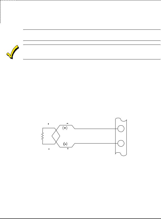
Wiring 2-Wire Smoke Detectors to Zone 1
1.Connect 2-wire smoke detectors across zone 1 terminals 8 (+) and 9 (–). Observe proper polarity when connecting the detectors.
2.If an EOL resistor is presently connected across zone 1 terminals, remove it. The EOL resistor must be connected across the loop wires at the last detector.
In UL installations, only zone 1 may be used as a fire zone. In addition, an ADEMCO Model 610–7 UL must be used as the end-of-line resistor at the last detector.
The alarm current provided by zone 1 supports only one smoke detector in the alarmed state.
COMPATIBLE 2-WIRE SMOKE DETECTORS
Detector Type |
System Sensor |
|
Model No. |
||
|
||
Photoelectric w/heat sensor, direct wire |
2300TB |
|
Photoelectric, direct wire |
2400 |
|
Photoelectric w/heat sensor, direct wire |
2400TH |
|
Photoelectric |
2451 w/B401B base |
|
Photoelectric w/heat sensor |
2451TH w/B401B base |
|
Ionization, direct wire |
1400 |
|
Ionization |
1451 w/B401B base |
|
Photoelectric duct detector |
2451 w/DH400 base |
|
Ionization duct detector |
1451D w/DH400 base H |
|
Low-profile, photoelectric, w/135°F thermal |
2100T |
|
Low-profile, ionization type, direct wire |
1100 |
2000 OHMS 2k EOLR |
SMOKE |
2-WIRE SMOKE
DETECTOR
UL NOTE:
IN UL INSTALLATIONS, ONLY ZONE 1
MAY BE USED FOR FIRE.
8
ZONE 1
9
Figure 8. 2-Wire Smoke Detector Connected to Zone 1
Wiring 4-Wire Smoke/Combustion Detectors on Zones 2-6
The system supports as many 4-wire detectors as can be powered from Auxiliary Power on the control on zones 2-6. Refer to the detector’s instructions for complete details regarding its proper installation and operation.
1.Connect 12-volt power for the detectors from Auxiliary Power terminals 4 and 5 (which interrupts power for fire alarm reset). Observe proper polarity when connecting detectors.
2.Connect detectors (including heat detectors, if used) across terminals of the zone selected (zones 2-6 may be used). All detectors must be wired in parallel.
4–2

Section 4 - Basic Hardwired Zones 1-6
Remove 2000 ohm EOL resistor if connected across the selected zone terminals. You must connect the EOL resistor across the loop wires at the last detector.
To supervise power, we recommend the use of a System Sensor No. A77-716B Supervisory Module.
Compatible 4-Wire Smoke/Combustion Detectors
System Sensor |
4-wire ionization products of combustion detector |
1412 |
|
|
|
System Sensor |
4-wire photoelectric smoke detector |
2412 |
|
|
|
System Sensor |
4-wire photoelectric smoke detector w/135° F (57° C) heat |
2412TH |
detector |
|
|
System Sensor |
EOL relay module (supervisory module for wired 4-wire |
A77716B |
fire zone). |
|
|
System Sensor |
low-profile 4-wire photoelectric smoke detector w/135° F |
2112/24T |
(57° C) heat detector |
|
|
AUX PWR + 5  OUTPUT
TERMINALS 4
BLK |
+ RED |
|
4-WIRE SMOKE |
EOL |
|
|
OR COMBUSTION |
||
|
POWER |
||
+ |
DETECTORS |
||
SUPERVISION |
|||
+ |
|||
RELAY MODULE |
|||
|
|
||
|
VIOLET |
A77-716B |
TO HI SIDE OF SELECTED
ZONES 2-6
TO LO SIDE OF
SELECTED
+ |
2000 |
|
OHMS |
||
EOLR |
||
|
||
HEAT |
HEAT |
|
DETECTOR |
DETECTOR |
Figure 9. 4-Wire Smoke Detector Connections (Zones 2–6)
Verifying Smoke Detector Operation
The control panel “verifies” any alarm by resetting the smoke detectors after the first alarm trigger, and then waiting 90 seconds for a second alarm trigger. If the smoke detector or thermostat does not trigger again, the control disregards the first trigger, and no alarm signal occurs. This feature eliminates false alarms due to electrical or physical transients.
Turning Off Fire Alarm Sounding
You can turn off fire alarm sounding by pressing the OFF key on any keypad or other arming/disarming device. To clear the “memory of alarm” and to reset the detector’s alarm, enter the security code plus OFF again.
4–3

VISTA-15/VISTA-15CN Installation and Setup Guide
Programming Hardwired Zones
Each zone must be programmed into the system using the 56 Zone Programming Mode or58 Expert Programming Mode, which assigns characteristics that define the way the system responds to faults on that zone. Refer to Section 14: Zone Response Type Definitions and Section 16: Zone Programming for specific instructions on programming hardwired zones.
Checkout Procedure for Hardwired Zones
After complete installation and programming of all hardwired devices, check the security system as follows:
1.Make certain that all devices and sensors connected to the hardwired zones are not in a faulted state. Doors and windows with contacts should be closed, PIRs should be covered (use a cloth to mask them temporarily, if necessary).
2.Plug in the AC transformer if you have not already done so.
With all hardwired zones intact, the alpha keypad connected to the system should display:
DISARMED
READY TO ARM.
3. If the following is displayed,
DISARMED–Press
to show faults
press [ ] to display the faulted zone(s). Restore any faulted zone(s) as necessary (also make sure that you have connected a 2000 ohm EOL resistor across the terminals of unused zones).
When the DISARMED...READY TO ARM message is displayed, you can proceed to the next step.
4.Fault and then restore every contact or sensor on each zone individually to ensure that it is being monitored by the system. Each time a zone is faulted, the keypad should display the number of the faulted zone. When each zone is restored, the READY TO ARM message should appear again.
You need to observe the keypad as each zone is faulted and restored.
When you get the proper displays on the keypad(s), the hardwired zones in the system are functioning properly.
5. Unplug the AC transformer.
4–4

S E C T I O N 5
Wired Zone Expansion
∙ ∙ ∙ ∙ ∙ ∙ ∙ ∙ ∙ ∙ ∙ ∙ ∙ ∙ ∙ ∙ ∙ ∙ ∙ ∙ ∙ ∙ ∙ ∙ ∙ ∙ ∙ ∙ ∙ ∙ ∙ ∙ ∙ ∙ ∙ ∙ ∙ ∙ ∙ ∙ ∙ ∙ ∙ ∙ ∙ ∙ ∙ ∙ ∙ ∙
In This Section
♦ Installing Zone Expansion Units |
♦ Programming Wired Expansion Zones |
♦ Connections and Setup |
♦ Checkout Procedure for Wired Expansion Zones |
∙ ∙ ∙ ∙ ∙ ∙ ∙ ∙ ∙ ∙ ∙ ∙ ∙ ∙ ∙ ∙ ∙ ∙ ∙ ∙ ∙ ∙ ∙ ∙ ∙ ∙ ∙ ∙ ∙ ∙ ∙ ∙ ∙ ∙ ∙ ∙ ∙ ∙ ∙ ∙ ∙ ∙ ∙ ∙ ∙ ∙ ∙ ∙ ∙ ∙
Installing Zone Expansion Units
You can add 8 wired EOLR zones to the basic control's 6 zones, for a total of 14 wired zones, by using a 4219 Wired Expansion Unit or 4229 Wired Expansion/Relay Unit.
Location |
• You can mount an expansion unit within the control cabinet if space |
|
permits. Otherwise, mount the unit outside the cabinet. |
Supervision |
• Units are supervised against removal. Keypads display CHECK and |
|
ZONE 09 if a zone expander is disconnected. |
|
• Units have tamper protection for security when mounted outside of |
|
the cabinet. |
Zone Information • Assign zone numbers 10–17 for the eight wired expansion loops (designated A to H in Figure 10 and Figure 11). You can program these zones individually (in 56 Zone Programming Mode or 58 Expert Programming Mode). Expansion zones must also be programmed as input type 2 (AW) when prompted.
Connections and Setup
OFF |
ON |
1 |
ON |
2 |
< < |
3 |
|
4 |
|
5 |
|
To add an expansion module, perform the following steps:
1.Connect the 4219 or 4229 module to the control's keypad terminals (see Figure 10. Wiring Connections - 4219 Expansion Module or Figure 11. Wiring Connections - 4229 Expansion/Relay Module).
2.Set the 4219 or 4229's DIP switch for device address “1” (switch 2 in the OFF position and switches 3, 4, 5 in the ON position). Switch 1 determines expansion zone A's response time (ON = normal response, OFF = fast response). For location of the DIP switch in both the 4219 and 4229 units, see figures that follow on next page.
For additional information, see instructions supplied with the 4219 and 4229 modules.
5–1

VISTA-15/VISTA-15CN Installation and Setup Guide
DIP SWITCH FOR SETTING |
|
ADDRESS AND ZONE A |
4-PIN CONSOLE PLUG |
RESPONSE TIME |
(CONNECTIONS SAME AS TB2) |
REED (TAMPER)
SWITCH
TAMPER JUMPER POSITION IN CABINET (NOT TAMPER PROTECTED)
REMOTE TAMPER PROTECTED
4219
|
|
|
|
|
|
|
|
|
|
|
|
TB2 |
|
|
|
|
|
|
|
|
|
|
|
|
|
|
4 |
GRN |
DATA OUT |
|
|
|
|
|
|
|
|
|
|
|
|
|
TO CONTROL |
|
|
|
|
|
|
|
|
|
|
|
|
|
|
|
|
|
|
|
|
|
|
|
|
|
|
|
4 |
3 |
BLK |
(–) GROUND |
|
|
|
|
|
|
|
|
|
|
|
|
|
|
|
|
|
|
|
|
|
|
|
|
|
|
3 |
2 |
RED |
(+) 12VDC |
TB1 |
|
|
|
|
|
|
|
|
|
|
2 |
|
|
|
|
|
|
|
|
|
|
|
|
|
|
|
YEL |
DATA IN FROM |
|
|
|
|
|
|
|
|
|
|
|
|
1 |
1 |
||
1 |
2 |
3 |
4 |
5 |
6 |
7 |
8 |
9 |
10 |
11 |
|
CONTROL |
||
12 |
|
|
||||||||||||
|
|
|
|
|
|
|
|
|
|
|
|
TERMINATE EACH PROGRAMMED |
||
|
|
|
|
|
|
|
|
|
|
|
|
ZONE WITH 1000 OHM (1K) |
||
|
|
|
|
|
|
|
|
|
|
|
|
END-OF-LINE RESISTOR |
||
|
|
|
|
|
|
|
|
|
|
|
|
(EACH ZONE'S LOOP RESISTANCE: |
||
|
A |
B |
C |
|
D |
|
E |
F |
|
G |
H |
300 OHMS + EOL) |
||
ZONES
Figure 10. Wiring Connections - 4219 Expansion Module
OFF 
 ON
ON
 5 4 3 2 1
SWITCH SHOWN FOR ADDRESS "0"
➞ ➞ ➞ ➞
SWITCH NUMBER
1
2
3
4
5
4229 ADDRESS SETTINGS ("—" means "OFF")
0 |
1 |
2 |
3 |
4 |
5 |
6 |
|
7 |
8 |
9 |
10 |
11 |
12 |
13 |
14 |
15 |
ON |
|
|
|
|
|
|
|
|
|
|
|
|
|
|
|
|
ON |
— |
ON |
— |
ON |
— |
ON |
— |
ON |
— |
ON |
— |
ON |
— |
ON |
— |
|
ON |
ON |
— |
— |
ON |
ON |
— |
— |
ON |
ON |
— |
— |
ON |
ON |
— |
— |
|
ON |
ON |
ON |
ON |
— |
— |
— |
— |
ON |
ON |
ON |
ON |
— |
— |
— |
— |
|
ON |
ON |
ON |
ON |
ON |
ON |
ON |
|
ON |
— — |
— |
— |
— |
— |
— |
— |
|
RELAYS SHOWN
DE-ENERGIZED
|
RLY |
|
RLY |
|||||
|
1 |
|
2 |
|||||
|
|
|
|
|
|
|
|
|
C |
NC NO GND |
C NC |
NO |
|||||
BRN |
ORG YEL BLK |
VIO GRY |
WHT |
|||||
RELAY  CONNECTOR
REED (TAMPER)
SWITCH
TAMPER JUMPER POSITION IN CABINET (NOT TAMPER PROTECTED)
REMOTE
TAMPER PROTECTED
DIP SWITCH FOR SETTING |
|
EITHER OR BOTH |
|
|
|
|
|
|||||||||
ADDRESS AND ZONE A |
|
|
|
|
|
|
|
|||||||||
RESPONSE TIME |
|
|
|
CAN BE USED |
|
|
|
|
|
|
||||||
RELAY |
|
|
|
|
|
|
|
|
|
|
|
4229 |
|
|
|
|
2 |
|
|
|
|
|
|
|
|
|
|
|
|
|
|
|
|
|
|
|
|
|
|
|
|
|
|
|
|
|
|
|
TERMINALS ON |
|
|
|
|
|
|
|
|
|
|
|
|
|
|
|
|
CONTROL PANEL |
|
RELAY |
|
|
|
|
|
|
|
|
|
|
|
|
|
|
||
|
1 |
|
|
|
|
|
|
|
|
|
|
|
TB2 |
|
|
|
|
|
|
|
|
|
|
|
|
|
|
|
|
|
|
|
|
NO C NC |
|
|
|
|
|
|
|
|
|
|
|
|
4 |
GRN DATA OUT |
(TERM 6) |
|
|
|
|
|
|
|
|
|
|
|
|
|
|
|
TO CONTROL |
||
|
|
|
|
|
|
|
|
|
|
|
|
|
|
|
|
|
|
|
|
|
|
|
|
|
|
|
4-PIN |
4 |
3 |
BLK |
(–) GROUND |
(TERM 4) |
|
|
|
|
|
|
|
|
|
|
|
|
|
|
|
|||
|
|
|
|
|
|
|
|
|
CONSOLE |
|
|
|
|
|||
|
|
|
|
|
|
|
|
|
3 |
2 |
RED |
(+) 12VDC |
(TERM 5) |
|||
|
|
|
|
|
|
|
|
|
|
PLUG |
||||||
TB1 |
|
|
|
|
|
|
|
|
|
2 |
|
|||||
|
|
|
|
|
|
|
|
|
|
|
|
|
YEL |
DATA IN FROM |
|
|
|
|
|
|
|
|
|
|
|
|
|
|
1 |
1 |
(TERM 7) |
||
1 |
2 |
3 |
4 |
5 |
6 |
7 |
8 |
9 |
10 |
11 |
12 |
|
CONTROL |
|||
|
|
|
|
|||||||||||||
|
|
|
|
|
|
|
|
|
|
|
|
|
TERMINATE EACH PROGRAMMED |
|||
|
|
|
|
|
|
|
|
|
|
|
|
|
ZONE WITH 1000 OHM (1K) |
|
||
|
|
|
|
|
|
|
|
|
|
|
|
|
END-OF-LINE RESISTOR |
|
||
|
|
|
|
|
|
|
|
|
|
|
|
|
(EACH ZONE'S LOOP RESISTANCE: |
|||
|
A |
B |
C |
|
D |
E |
|
F |
|
G |
H |
|
300 OHMS + EOL) |
|
||
ZONES
Figure 11. Wiring Connections - 4229 Expansion/Relay Module
5–2
Section 5 - Wired Zone Expansion
Programming Wired Expansion Zones
Each zone must be programmed into the system using the 56 Zone Programming Mode or58 Expert Programming Mode, which assigns characteristics that define the way the system responds to faults on that zone. Refer to Section 14: Zone Response Type Definitions and Section 16: Zone Programming for specific instructions on programming wired expansion zones.
Checkout Procedure for Wired Expansion Zones
Whenever it becomes necessary to disconnect power in order to add a module or keypad, always disconnect the battery first, then the AC transformer. After installation has been completed, connect the AC transformer first, then the battery.
After you have completed installation and programming of all devices, check all expansion zones in the security system as follows:
1.Make certain that all devices and sensors connected to the wired expansion zones are not in a faulted state. Doors and windows with contacts should be closed, PIRs should be covered (use a cloth to mask them temporarily, if necessary).
2.Plug in the AC transformer. With all zones intact (including hardwired zones), the alpha keypad connected to the system should display:
DISARMED
READY TO ARM.
3. If the following is displayed,
DISARMED–Press
to show faults
press [ ] to display the faulted zone(s). Restore any faulted zone(s) as necessary (also make sure that you have connected a 1000 ohm EOL resistor across the terminals of unused expansion zones on the 4219 or 4229 Module).
When the READY TO ARM message is displayed, you can proceed to the next step.
4.Fault and restore every contact or sensor in each expansion zone individually to ensure that it is being monitored by the system. Each time a zone is faulted, the keypad should display the number of the faulted zone. When each zone is restored, the READY TO ARM message should appear again.
You need to observe the keypad in each zone, as each zone is faulted and restored.
When the proper displays appear on the keypad(s), the wired expansion zones in the system are functioning properly.
5.Unplug the AC transformer.
A CHECK 09 message on the display signifies one of two problems:
∙Data from the control is not reaching the zone expander module. Check the wiring and DIP switch settings.
or
∙The tamper jumper is on in the Expansion Module and the Expansion Module cover is off.
5–3

VISTA-15/VISTA-15CN Installation and Setup Guide
5–4
 Loading...