


9,67$3
HFXULW\6\VWHP
6
K0736V1 10/02
8
VHU
*
XLGH
®

IMPORTANT!
PROPER INTRUSION PROTECTION
For proper intrusion coverage, sensors should be located at
point of entry
to a home or commercial premises. This would include any
every possible
skylights that may be present, and the upper windows in a multi-level building.
In addition, we recom mend that radio backup be us ed in a security system so
that alarm signals can sti ll be sent to the Cen tral Moni toring Station in the e vent
that the telephone lines are out of order ( alarm signals are nor mally sent over
the phone lines).
EARLY WARNING FIRE DETECTION
Early warning fire detection is impor tant in a home. Smok e and heat detectors
have played a key role in reduci ng fire deaths in the Unit ed States. W ith regard
to the number and placement of smoke/heat detectors, we subscribe to the
recommendations contained in the National Fire Protection Association's
National Fire Alarm Code (NFPA 72). Thes e recomm endations can be f ound on
page 43 of this manual.
This manual is a step-by-step guide that will acquaint you with the system's
features and benefits. It def ines the components and their functions, describes
their operation, and provides clear step-by-step instructions for normal and
emergency procedur es. K eep this m anual in a c onv enie nt place so t hat you ca n
refer to it as necessary.
$ERXW7KLV0DQXDO
– 2 –

7DEOHRI&RQWHQWV
System Overview....................................................................................................................5
Introduction ..........................................................................................................................5
System Basics .......................................................................................................................5
Using the Voice Message Center.........................................................................................7
About The Keypads................................................................................................................8
General Information.............................................................................................................8
Functions of the Keypads...................................................................................................10
Entry/Exit Delays .................................................................................................................12
Exit Delay............................................................................................................................12
Entry Delay......................................................................................................................... 12
Exit Alarms.........................................................................................................................13
Checking For Open Zones..................................................................................................14
Using the [∗] Key................................................................................................................14
Arming the System...............................................................................................................15
Stay Mode: Arms Perimeter Only, Entry Delay On.........................................................15
Night-Stay Mode: Arms Perimeter Only, Plus Selected Zones .......................................15
Instant Mode: Arms Perimeter Only, Entry Delay Off....................................................15
Away Mode: Arms Entire System, Entry Delay On.........................................................15
Maximum Mode: Arms Entire System, Entry Delay Off.................................................15
Arming Commands.............................................................................................................16
Single Button Arming ........................................................................................................17
Step Arming Feature..........................................................................................................17
Using the Keyswitch............................................................................................................18
Using the Keyswitch........................................................................................................... 18
Disarming and Silencing Alarms......................................................................................19
Using the [OFF] key...........................................................................................................19
Bypassing Protection Zones .............................................................................................. 20
Using the BYPASS Key......................................................................................................20
Quick Bypass ......................................................................................................................21
Chime Mode...........................................................................................................................22
Date and Time.......................................................................................................................23
Viewing the Current Date and Time.................................................................................23
Setting the Date and Time.................................................................................................23
– 3 –

7DEOHRI&RQWHQWV
Panic Keys..............................................................................................................................24
Using Panic Keys................................................................................................................24
Macro Key Programming & Usage...................................................................................25
About Macro Keys............................................................................................................... 25
Example of Macro Programming.......................................................................................26
Using a Programmed Macro Key.......................................................................................26
Using Device Commands....................................................................................................27
About Device Commands ...................................................................................................27
Paging Feature .....................................................................................................................28
About Automatic Paging ....................................................................................................28
Manual Paging....................................................................................................................29
Latch Key Paging ...............................................................................................................29
Security Codes & Authority Levels..................................................................................30
About Security Codes .........................................................................................................30
Authority Level Definitions ............................................................................................... 30
How to Assign User Codes and Attributes........................................................................31
Scheduling .............................................................................................................................32
About Scheduling................................................................................................................32
Creating Schedules.............................................................................................................32
Event Logging Procedures.................................................................................................34
About Event Logging..........................................................................................................34
Viewing the Event Log ....................................................................................................... 34
Table of Event Log Codes...................................................................................................35
Testing the System (To Be Conducted Weekly)............................................................36
About Testing the System ..................................................................................................36
Trouble Conditions..............................................................................................................37
Maintaining Your System...................................................................................................40
Fire Alarm System (If Installed).......................................................................................41
Quick Guide to Basic System Functions ........................................................................45
Summary of Audible/Visual Notifications......................................................................46
Regulatory Statements and Warnings ............................................................................48
Charts of Your System’s Features....................................................................................49
– 4 –

,QWURGXFWLRQ
Congratulations on your ownership of the VISTA-10P Security System. You've made a
wise decision in choosing it, for it represents the latest in security protection technology
today. This system provides:
• Three forms of protection: burglary, fire* and emergency
• At least one keypad which provides control of system and displays system status
• Various sensors for perimeter and interior burglary protection
• Smoke or combustion detectors* designed to provide early warning in case of fire.
Your system may also have been programmed to automatically send alarm or status
messages over the phone lines to a Central Monitoring Station.
* Commercial installations and some residential systems may not include fire
protection – check with your installer.
6\VWHP%DVLFV
Burglary Protection
• Several modes of burglary protection: Stay, Night-Stay, Away, Instant, Maximum.
STAY: arms perimeter zones only and entry delay is on
INSTANT: same as STAY, except entry delay is off
NIGHT-STAY: arms perimeter zones and selected interior zones; entry delay on
AWAY: arms perimeter and all interior zones, entry delay is on
MAXIMUM: same as AWAY, except entry delay is off
• You can BYPASS selected zones while leaving the rest of the system armed.
• CHIME mode alerts you to the opening of protected doors and windows while the
system is disarmed.
Fire Protection
• Fire protection is always active (if installed) and an alarm sounds if a fire
condition is detected
• If necessary, you can manually initiate a fire alarm using the keypad (if
programmed).
• Refer to the Fire Alarm System section for information regarding fire protection,
smoke detectors and planning emergency exit routes.
Security Codes
• You were assigned a 4-digit security code during system installation.
• Use your security code when arming and disarming the system, and when
performing other system functions.
• Other users can be assigned different security codes, each with different
authority levels, which define the system functions a particular user can perform.
6\VWHP2YHUYLHZ
– 5 –

6\VWHP2YHUYLHZ
Zones
• The system sensing devices have been assigned to various “zones,” which are
specific areas of protection (e.g., front door, kitchen window, etc.).
• Zone numbers are displayed at the keypad when an alarm or trouble condition
occurs on a sensor.
Arming, Step-Arming and Disarming Burglary Protection
• The system must be armed before the burglary protection can sense intrusions.
• To arm your system, enter your user code followed by t h e desired arming key.
• If programmed, the [#] key can be pressed instead of entering the security code
when arming the system.
• You can also use the step-arming key, if programmed, to arm the system, which
lets you use a function key to a rm the system in one of three modes by simply
pressing the key repeatedly.
• To disarm the system, enter your user code then press the [OFF] key.
Alarms
• When an alarm occurs, both the keypad and external sounders will sound, and
the keypad will display the zone(s) causing the alarm.
• If your system is connected to a Central Monitoring Station, an alarm message
will also be sent.
• To stop the alarm sounding, simply disarm the system.
Memory of Alarm
• When an alarm condition occurs, the keypad displays the number(s) of the
zone(s) that caused the problem, and displays the type of alarm (e.g., “fire”).
• The message remains displayed even after disarming the system, but can be
cleared with another “off” sequence.
Phone Access
• If included, a phone module permits you to access the system via a touch-tone
phone, either on-premises or by calling-in when away.
• You can receive synthesized voice messa ges over the telephone regarding the
status of the security system.
• You can arm and disarm the system and perform most function commands
remotely via the telephone, with voice confirmation provided after each comma n d
entry.
• Complete information regarding the use of this feature is provided in a separate
manual entitled “Phone Access User's Guide” that is supplied with the voice
module.
&RQWLQXHG
– 6 –
6\VWHP2YHUYLHZ
&RQWLQXHG
Paging Feature
• If programmed, the system can automatically send certain system condition
messages to a pager.
• The display consists of code numbers that indicate the type of condition that has
occurred.
Function Keys
• The “A”, “B”, “C”, and “D” keys on the keypad can be programmed to perform
various functions.
• Functions include: activate a Panic alarm; arm the system; provide step arming;
switch lights on/off; send a message to a pager; display Time/Date; start a Macro
Scheduling
• Your system can be programmed to automatically perform certain functions (e.g.,
arm the system) at a predetermined time each day.
8VLQJWKH9RLFH0HVVDJH&HQWHU
The Voice Keypads feature a voice message center
that lets you record and playback one message.
• The message can be up to 2.5-minutes long
• The message remains in the keypad’s memory
until a new message is recorded.
• The volume control of the message is adjustable.
• Refer to the procedures below when using the
Message Center functions.
Message Center Functions
To…
record a
message
end
Press these keys…
[#] FUNCTION + [0] VOICE + [1] RECORD
[1] RECORD
recording
play a
[#] FUNCTION + [0] VOICE + [3] PLAY
message
adjust the
volume
[#] FUNCTION + [0] VOICE + [2] VOLUME keys,
then press volume key [3] ↑ (up) or [6] ↓ (down)
PLAY KEY
RECORD
KEY
1
RECORD
4
7
STATUS
VOICE
KEY
OFF
MAX
INSTANT
READY
VOLUME
AWAY
2
VOLUME
TEST
5
CODE
8
0
VOICE
FUNCTION
KEY
ARMED
READY
MESSAGE
LCD
DISPLAY
MIC
STATUS
KEY
SPEAKER
LEDs
MICROPHONE
Notes…
The red MESSAGE LED lights.
Message remains in memory
until a new message is recorded.
The red MESSAGE LED flashes,
indicating message waiting.
The recorded message plays and
the red MESSAGE LED turns off.
Adjusting message volume also
adjusts status volume. Volume
cannot be adjusted while playing.
AND
UP VOLUME
KEY
STAY
3
PLAY
BYPASS
6
CHIME
9
#
FUNCTION
DOWN
VOLUME
6160V-00-005-V0
– 7 –

$ERXW7KH.H\SDGV
*HQHUDO,QIRUPDWLRQ
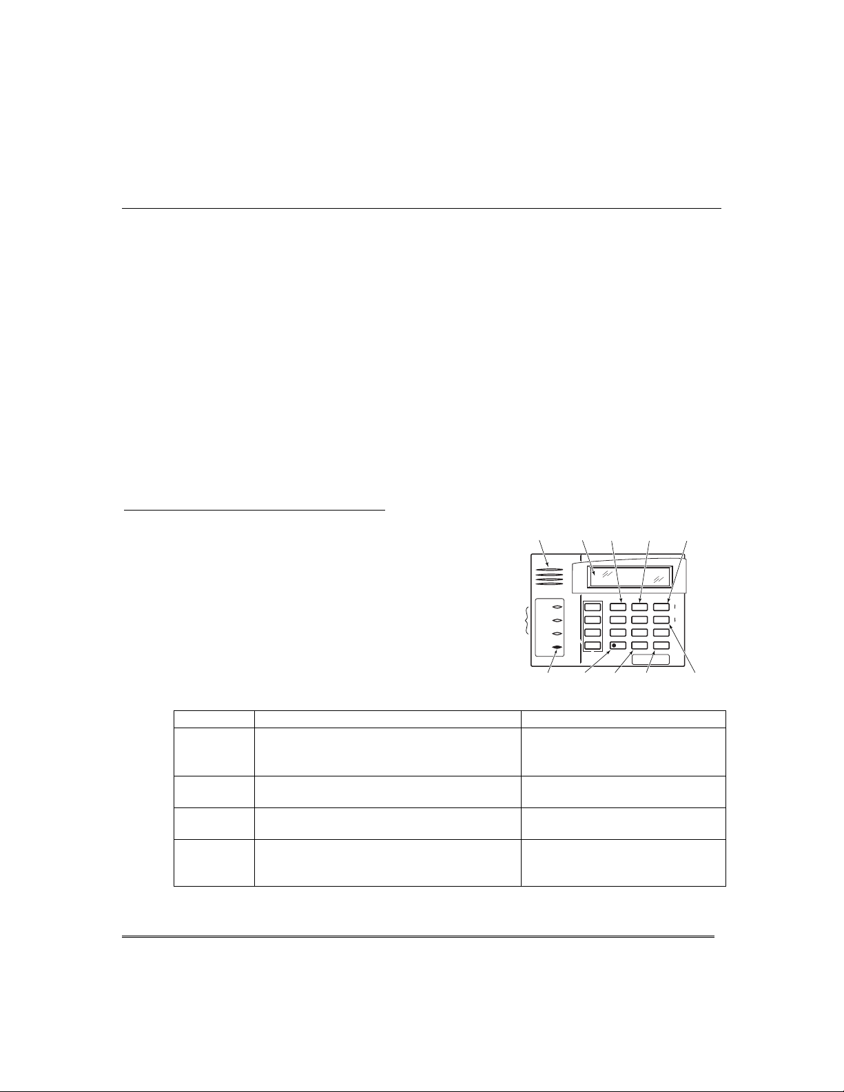
Your keypads allow you to control all system functions. The keypads feature the
following:
A telephone style (digital ) keypad
•
Liquid Crystal Display (LCD) which shows the nature and location of all
•
occurrences
Built-in sounder which will sound during alarms and troubles. The sounder also
•
"beeps" during certain system funct ions and when depressing any of the keys (to
acknowledge the key press).
Backlighting of the LCD display windows. Backlighting turns on when any key is
•
pressed, and when opening an entry/exit door while the system is armed. This
feature is helpful when a keypad is located in a dimly lit area.
IMPORTANT:
that an alarm has occurred during your absence and an intruder may still be on the
premises. LEAVE IMMEDIATELY and CONTACT THE POLICE from a nearby safe
location.
If the keypad beeps rapidly upon entering the premises, it indicates
Your keypads are functionally th e same, but may have different types of displays,
depending on the type installed with your system. To access the keys on the keypad,
simply open the swing-down door.
Alpha Display
2-line alpha display keypads feature a 2-line, 32-character
alphanumeric LCD which can display syst em messages in
friendly English. These keypads can also be programmed with
Fixed-Word Display
custom zone descriptors.
Fixed-Word display keypads are functionally identical to Alpha
display keypads, but the LCD display uses pre-designated
Voice Keypads
Voice Keypads (if installed), are functionally the same as other
words to identify the nature and location of occurrences.
keypads, except that these keypads can provide the following:
Voice announcements of system status (see
•
Open Zones
Voice chime, which can alert you to the opening of doors and
•
section)
Checking for
windows while the system is disarmed (see Voice Chime in
Chime mode
Message center, which lets you record and playback
•
section)
messages (see Using the Voice Message Center in the
System Overview
section).
– 8 –

$ERXW7KH.H\SDGV&RQWLQXHG
)L[HG:RUG'LVSOD\.H\SDG
AWAY:
STAY:
INSTANT:
Lit with STAY = Instant mode
BYPASS:
NOT READY:
NO AC:
AC:
CHIME:
BAT:
All burglary zones, interior and
perimeter, are armed.
Perimeter burglary zones, such as
protected windows and doors, are
armed.
Entry delay is turned off:
Lit with AWAY = Maximum mode
This appears when one or more burglary protection zones have been
bypassed.
Appears when burglary portion of the system is not ready for arming
(due to open protection zones). The system is ready to arm when this
message disappears and the READY indicator light comes on.
Appears when AC power has been cut off. System is operating on
backup battery power.
Appears when AC power is present.
Appears when the CHIME feature is activated.
Low battery condition in a wireless sensor (if zone number displayed)
or low system battery (if no zone number displayed).
ALARM
FIRE
FIXED-WORD DISPLAY (6150 shown)
CHECK INSTANT CANCELED
AWA Y
BYPASS
STAY
NIGHT NO AC
PHONE TEST
NOT READY
CHIME BAT
6150disp
ALARM:
Appears when an intrusion has been detected and the system is armed
(also appears during a fire alarm or audible emergency alarm).
Accompanied by the protection zone in alarm.
CHECK:
Appears when a mal function is discovered in the system at any time or
if an open is detected in a FIRE zone at any time or a fault in a
DAY/NIGHT burglary zone during a disarmed period. Accompanied by
a display of zone number in trouble.
FIRE
Appears when a fire alarm is present. Accompanied by a display of the
:
zone in alarm.
A FIRE display also appears when a fire alarm is manually activated,
accompanied by a display of emergency key zone number programmed
for fire.
– 9 –

)XQFWLRQVRIWKH.H\SDGV
NOTE:
keys indicate their primary purpose; the
functions printed under some of the keys
(shown in brackets under the respective key),
indicate their alternate o r secon d ary purpose.
DISPLAY WINDOW
Alpha Display Keypads:
Liquid Crystal Display (LCD) keypads that display
protection point identification, system status, and
messages.
Fixed-Word Display Keypads:
protection zone ID and system status messages using
pre-designated words in the LCD display area.
silences alarms and audible trouble indicators, and
clears visual display after problem's correction.
[RECORD]
with the FUNCTION and VOICE keys to record up
to a 2.5-minute message.
perimeter and interior.
[VOLUME]
with the FUNCTION and desired volume control
keys
message or voice system status.
system only. Interior protection is not armed,
allowing movement within premises without causing
an alarm.
[PLAY]
the FUNCTION and VOICE keys to play the
recorded message.
[ ↑ ]
FUNCTION and VOL UM E ke ys t o rai s e th e
message and voice system status volume.
perimeter and interior, but without entry delay
feature. Entering via an entry/exit door will cause an
alarm.
disarmed. Refer to
test procedures.
The functions printed directly on the
2-line, 32-character
1 OFF
2 AWAY
3 STAY
4 MAXIMUM
5 TEST
Disarms burglary portion of the
On Voice keypads, used in conjunction
Arms the entire burglary system,
On Voice keypads, used in conjunction
↑
↓
[3] or
On Voice keypads, used in conjunction with the
[6] to adjust the volume of a recorded
Arms perimeter portion of burglary
On Voice keypads, used in conjunction with
Arms the entire burglary system,
Tests the system and alarm sounder if
Testing The System
section for
Display
system,
6 BYPASS
being monitored by the system.
[ ↓ ]
On Voice keypads, used in conjunction with the
FUNCTION and VOLUME keys to lower the message
and voice system status volume.
7 INSTANT
mode, but without the entry delay feature.
KEYS 0–9:
perform their associated system functions after the
security code has been entered.
READY
✱
[STATUS]:
STATUS key annunciates the current system status.
Pressing the STATUS key a second time annunciates and
displays system and/or zone faults (if they exist).
0
[VOICE]
VOLUME and PLAY functions.
#
the system without use of a security code (if
programmed).
[FUNCTION]
voice or volume function.
FUNCTION KEYS:
programmed for a variety of functions, including panic
(emergency) functions. For details, see the
section.
ARMED LED INDICATOR:
system has been armed.
READY LED INDICATOR:
system is ready to be armed (no faults present). While the
system is disarmed, this indicator will go on and off as
protection zones are closed and opened.
MESSAGE LED INDICATOR:
keypads, flashes red when message waiting or lights red
(steady) when in record mode.
MIC
:
recordings.
INTERNAL SPEAKER:
the alarm sounder during alarms, and will also "beep"
during certain system functions. The speaker also
provides voice playback for any recorded messages.
Removes individual pro te ction zones from
Arms in manner similar to the STAY
Used to enter your security code(s) and to
Used to display all open protection zones.
On Voice keypads, a momentary press of the
On Voice keypads, enables the RECORD,
T
his key can be used for "Quick Arming" of
On Voice keypads, enables the desired
Keys A, B, C, D may have been
Function Keys
(RED) Lit when the
(GREEN) Lit when the
(RED) On Voice
On voice keypads, microphone for Message Center
The built-in speaker mimics
– 10 –

)XQFWLRQVRIWKH.H\SDGV&RQWLQXHG
SPEAKER
LCD
DISPLAY
LEDs
ARMED
READY
MESSAGE
MIC
MICROPHONE
FUNCTION
KEYS
OFF
1
RECORD
MAX
4
INSTANT
7
READY
STATUS
AWAY
2
VOLUME
TEST
5
CODE
8
0
VOICE
STAY
3
PLAY
BYPASS
6
CHIME
9
#
FUNCTION
6160V-003-V0
Voice-capable 2-line Alpha keypad
(shown with flip-down front door removed)
IMPORTANT!
When entering codes and commands, sequential key depressions must be made
•
within 4-5 seconds of one another. If 4-5 seconds elapse without a key depression, the
entry will be aborted and must be repeated from its beginning. Be sure to observe
this precaution when performing any of the procedures in this manual.
•
If you make a mistake while entering a security code, stop, press the [
] key, and
✱
then start over. If you stop in the middle while entering a code, and then
immediately start the entry over, an erroneous code might be entered.
– 11 –

(QWU\([LW'HOD\V
Your system has preset time delays, known as exit delay and entry delay.
([LW'HOD\
Exit delay gives you time to leave t hrough the designated exit door without setting
off an alarm. Exit delay begins immediately after arming your system in any arming
mode and Alpha Display keypads display the message “You May Exit Now.” When
“You may exit now” disappears, the system is fully armed. If programmed, a slow
beeping will sound during the exit delay period until the last 10 seconds, which then
changes to fast beeping (alerting you to the end of exit delay). If you cannot leave by
this time, you should stop, disarm the system, and start over to avoid a false alarm.
Exit Delay Restart/Reset.
after arming STAY, you can re-start the exit delay at any time – simply press the
[✱] key, then let that person in. The system automatically re-arms when exit delay
expires, which avoids having to disarm the system and then re-arm it again.
In addition, when the system is armed AWAY, reopening and closing the ent ry/exit
door before exit delay time expires (e.g., reentering to get a forgotten item) will reset
the exit delay time.
(QWU\'HOD\
Entry Delays give you time to disarm the system when you re-enter through the
designated entrance door. You must disarm the system (simply enter your security
code) before the entry delay period ends, or an alarm will occur. The keypad beeps
during the entry delay period, reminding you to disarm the system. There are two
entry delays (if programmed). The first is for your primary entrance and the second
can be used for a secondary entrance, where a longer delay is required to walk to the
keypad to disarm the system.
You can also arm the system with no entry delay at all by using the INSTANT or
MAXIMUM arming mode. This mode provides great er security while on the
premises or while away for extended periods of time.
See your installer for your delay times.
Exit D elay: seconds Entry Delay 1: seconds
If you wish to open the entry/exit door to let someone in
– 12 –
Entry Delay 2:
seconds

([LW$ODUPV
Whenever you arm the system, the exit delay begins. If an entry/exit door or interior
zone is faulted when the exit delay ends (e.g., exit door left open), t h e system sounds
an alarm and starts the entry delay timer. If you disarm the system before the entry
delay ends, the alarm sound stops and the message "CANCELED ALARM" or "CA " is
displayed on the keypad, along with a zone number indicating the faulted zone. No
message is sent to the Central Monitoring Station.
To clear the exit alarm condition, the open zone must be made intact; to clear the
display, enter your code plus OFF.
If you do not disarm the system before the entry delay ends, and an entry/exit door or
interior zone is still open, the alarm sound continues and an "exit alarm" message is
sent to the Central Monitoring Station. The message ""EXIT ALARM" or "EA" is
displayed on the keypad, along with a zone number indicating the faulted zone. To
stop the alarm, the system must be disarmed (your code plus OFF); to clear the
display, enter your code plus OFF a second time.
An “exit alarm” also results if an entry/exit door or interior z one is faulted within two
minutes after the end of the exit delay.
Your system may have been programmed for this feature to minimize fals e alarms sent to the Central
Monitoring Station. Ask your installer if "Exit Alarm" is active i n your system. If so, check this box.
(QWU\([LW'HOD\V
&RQWLQXHG
– 13 –
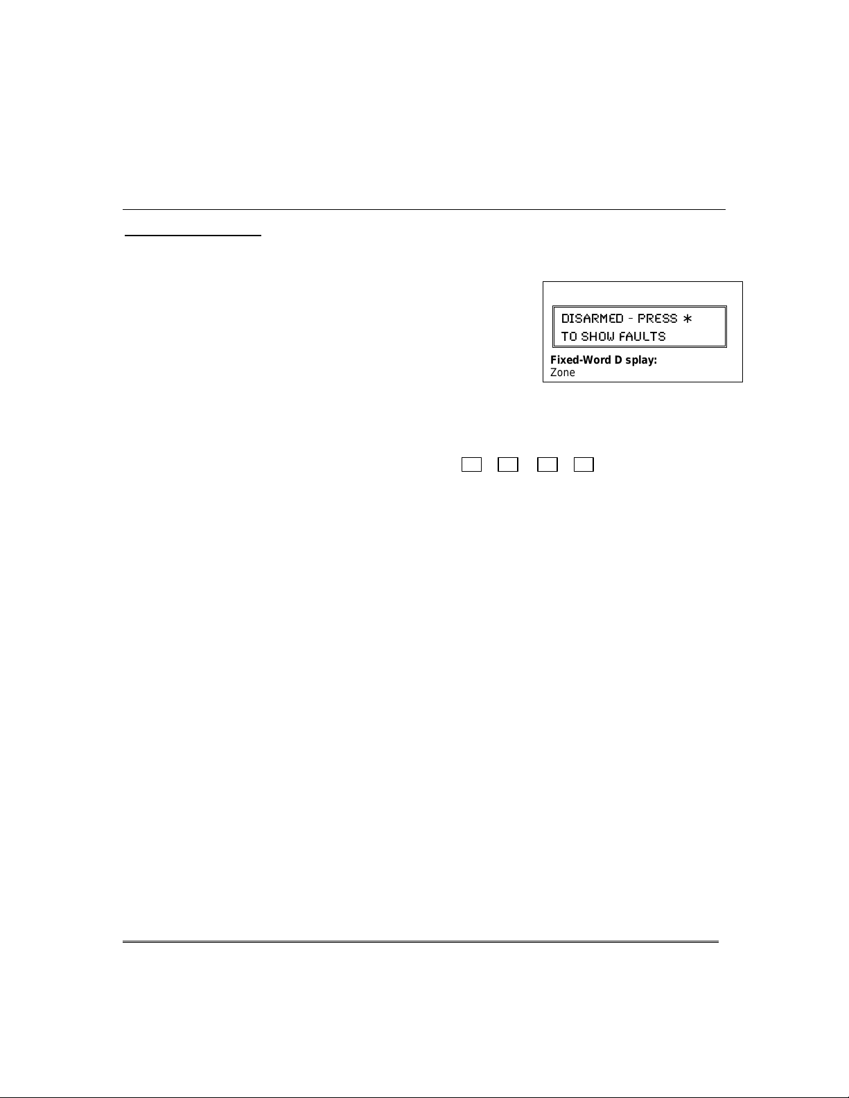
&KHFNLQJ)RU2SHQ=RQHV
8VLQJWKH>∗@.H\
B
efore arming your system, all protected doors, windows and other protection zones
must be closed or bypassed, otherwise the keypad will display a "Not Ready" message.
1. Press [∗] READY (do not enter code first) to display
faulted zones
2. Secure or bypass the zones displayed.
The keypad’s READY indicator lights when all
3.
protection zones have been either closed or bypassed.
4. Arm the system as desired.
Voice Status:
zones (up to 3 zone descriptors) if the Voice Status feature is turned on.
To turn the Voice Status feature on/off:
(also turns on Voice Chime mode; see
To announce Status:
To announce faulted zones:
seconds of the first press.
.
Voice Keypads (if installed), can announce system st at us and faulted
# + 0 + 2 + 4
Chime mode
section)
Press [∗] STATUS key once.
Press the [∗] STATUS key a second time within 5
Alpha Display:
(-7%61)( 46)77
83 7,3; *%9087
Fixed-Word Display:
Zone no. and “NOT READY”
∗
– 14 –

$UPLQJWKH6\VWHP
6WD\0RGH$UPV3HULPHWHU2QO\(QWU\'HOD\2Q
Used when you want to arm the system with persons staying inside (or if you have
•
pets that are moving throughout the premises ).
The perimeter sensors are armed, but interior sensors are left disarmed.
•
Exit delay begins (you can leave through the entry/exit door, if desired).
•
An alarm sounds if any protected window or non-entry/exit door is opened.
•
You may otherwise move freely within the premises.
•
Persons entering later can enter through an entry/exit door, but they must disarm
•
the system within the
1LJKW6WD\0RGH$UPV3HULPHWHU2QO\3OXV6HOHFWHG=RQHV
Use Night-Stay mode to provide increased security while staying inside.
•
Arms same as Stay mode, but also arms pre-sel ected interior sensors (programmed
•
by your installer), while other interior sensors are left disarmed.
Persons entering later can enter through an entry/exit door but they must disarm
•
the system
must not violate any of the programmed interior zones to avoid
and
sounding an alarm.
IMPORTANT:
•
alarm if anyone enters those areas (e.g., waking in the middle of the night). To avoid sounding an
alarm, you must disarm the system before any activity takes place in those interior zones.
When Night-Stay mode is on, the selected interior zones are armed and cause an
,QVWDQW0RGH$UPV3HULPHWHU2QO\(QWU\'HOD\2II
Used when staying inside and do not expect anyone to use an entry/exit door.
•
Arms same as Stay mode.
•
An alarm sounds immediately if any protected perimeter window or any door is
•
opened, including entry/exit doors.
IMPORTANT:
•
care in selecting this mode of arming.
Arming in this mode greatly increases the chance of false alarms. Use extreme
$ZD\0RGH$UPV(QWLUH6\VWHP(QWU\'HOD\2Q
Used when nobody will be staying inside (including pets).
•
The entire system (interior and perimeter) is armed.
•
Exit delay begins letting you leave through the entry/exit door.
•
An alarm sounds if a protected window or any door is opened, or if any movement
•
is detected inside your premises.
You can reenter through an entry/exit door, but you must disarm the system within
•
the
delay period to avoid sounding an alarm.
entry
0D[LPXP0RGH$UPV(QWLUH6\VWHP(QWU\'HOD\2II
Used when leaving the premises for extended periods (e.g., vacation).
•
Arms same as Away mode, but entry delay is off.
•
An alarm sounds same as Away mode, and sounds upon opening entry/exit doors.
•
delay period to avoid sounding an alarm.
entry
– 15 –

$UPLQJWKH6\VWHP
$UPLQJ&RPPDQGV
Before arming, close all perimeter doors and windows and make sure the Ready to Arm
message is displayed.
Modes of Arming
Mode
Stay
Night-Stay security code + [3] + [3]
Instant
Away
Maximum security code + [4] (MAXIMUM)
Quick Arming
If "Quick Arming" was programmed by the installer, the
place of the security code when arming the system in any of its arming modes.
However, the security code must always be used to disarm the system.
Function Key Arming
For any arming command, a function key may have also been programmed for your
system. If so, you c an p re ss an d ho ld the ap p ro p riate f u nc tio n ke y fo r 2 se co n d s to arm
the system. See your installer for the designated functions (see Single Button
Arming section).
Press these keys…
security code + [3] (STAY)
security code + [7] (INSTANT)
security code + [2] (AWAY)
Keypad Confir ms By…
•
three beeps
•
armed STAY message displayed
•
red ARMED indicator lights
•
three beeps
•
NIGHT-STAY message displayed
•
red ARMED indicator lights
•
three beeps
•
armed STAY message displayed
•
red ARMED indicator lights
•
also note that entry delay is turned off.
•
two beeps, or, if programmed, beeping for
duration of exit delay
•
armed AWAY message displayed
•
red ARMED indicator lights
Leave the premises through an entry/exit
door during the exit delay period to avoid
causing an alarm. The keypad beeps rapidly
during the last 5 seconds of the exit delay to
warn you that it is ending.
• same as Away (described above)
Note that entry delay is turned off.
key can be pressed in
[#]
– 16 –
6LQJOH%XWWRQ$UPLQJ
The “A”, “B”, “C”, and/or “D” keys on your keypad may have been programmed for
single-button arming. Note that while it will not be necessary to use a security code
for arming, a security code must always be used to disarm the system.
If Single-Button Arming is programmed:
• A function key has been assigned to a specific type of arming: STAY mode,
Night-STAY mode, AWAY mode, or STEP-ARMING (see Step-Armin g
paragraph).
• You DO NOT need to enter your security code before pressing the functi on key
(but you always need your security code to DISARM the system).
Before arming, close all perimeter doors and windows.
Press and hold the assigned function key for 2
1.
seconds (no code is required). Function keys are
shown below.
The keypad begins beeping and displays the armed
2.
message. The red ARMED indicator also lights.
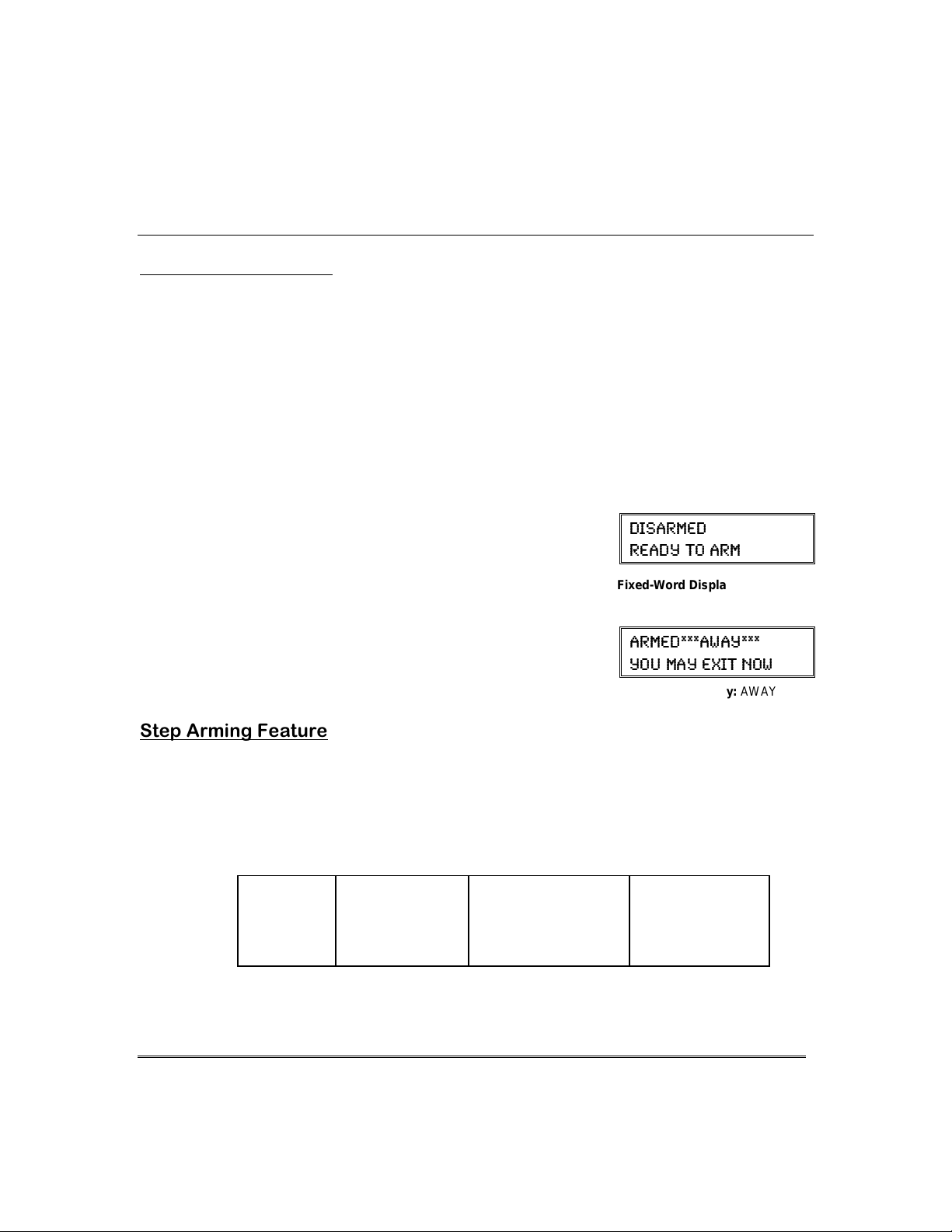
6WHS$UPLQJ)HDWXUH
Single-Button “Step” arming may have been programmed into one of the lettered keys
(A, B, C, or D). Check with your installer to see if this has been done in your system.
If Step-Arming is programmed:
• The assigned key provides a choice of three levels of security.
• The selected key can be pressed once, twice, or three times, increasing the level
of security with each press, as follows
Key
Ø
A, B, C, D
$UPLQJWKH6\VWHP
First Press
Ø
Armed-STAY Armed Night-STAY
Second Press
Ø
(if programmed)
Alpha Display:
(-7%61)(
6)%(= 83 %61
Fixed-Word Display:
Alpha Display:
%61)(%;%=
=39 1%= )<-8 23;
Fixed-Word Display:
Third Press
Ø
Armed-AWAY
READY
AWAY
– 17 –

8VLQJWKH.H\VZLWFK
GREEN
RED
8VLQJWKH.H\VZLWFK
Your system may be equipped with a k eyswitch for use when arming and disarming.
Red and green lights on the keyswitch plate indicate the stat us of your system as
follows:
Green Light: Lights when the system is disarmed and ready to be armed (no
open zones). If the system is disarmed and the green light is off, it
indicates the system is not ready (one or more zones are open).
Red Light: Lights or flashes when system is armed in AWAY or STAY mode.
See your installer for the meanings of the lit red light:
system armed STAY and exit delay has expired
Flashing = system armed STAY and exit delay timer active
Rapid flashing = an alarm has occurred (memory of alar m).
Before arming, close all perimeter doors and windows.
To arm in the AWAY mode:
Turn the key to the right for 1/2 second and release.
Keypads beep twice and the red indica tor lights or
flashes.
To arm in the STAY mode:
Turn the key to the right and hold for longer than 1
second, then release. Keypads beep three times and
the red indicator lights or flashes.
To disarm the system:
Turn the key to the right and releas e. The red light
turns off
Lit Steady = system armed AWAY or
– 18 –

8VLQJWKH>2))@NH\
The OFF key is used to disarm the system, silence alarm and trouble sounds, and
clear alarm memories.
IMPORTANT: If you return and the main burglary sounder is on,
CONTACT THE POLICE from a nearby safe loc ation.
If you return after an alar m has oc c urred and t he main s ounde r has s hut it self of f ,
beep rapidly upon your entering, indicating that an alarm has occurred during your
absence.
LEAVE AT ONCE, and CONTACT THE POLICE from a ne arby safe location.
+ 1
1.
(Security Code)
The “READY” indicator light will be lit if all zones
are secure, and the keypad will emit a single tone to
confirm that the system is disarmed.
NOTE: If entry delay has started (you’ve opened the
entry door), you do not need to press the OFF key;
simply enter your security code.
To Silence a Burglary Alarm and Clear a Memory of Alarm
2.
Enter your security code. This disarms the system and silences the alarm (or
warning tones of a Memory of Alarm).
Note the zone in alarm on the keypad display, and make that zone intact (close
door, window, etc.). Now enter the security code plus OFF to clear the keypad’s
Memory of Alarm display.
To Silence a Fire Alarm and Clear Memory of Alarm
3.
Simply press the OFF key to silence the alarm. Then enter the security code plus
OFF sequence to clear the keypad's Memory of Alarm display. See the Fire Alarm
System section.
'LVDUPLQJDQG6LOHQFLQJ$ODUPV
DO NOT ENTER, but
the keypad will
Alpha Display:
OFF
(-7%61)(
6)%(= 83 %61
Fixed-Word Display: READY
– 19 –

%\SDVVLQJ3URWHFWLRQ=RQHV
8VLQJWKH%<3$66.H\
Use t
his key when you want to arm your system with one or more zones intentionally
unprotected.
Vent Zones: Your system may have certain window s set as “vent” zones, which are
automatically bypassed if left open when arming the system (you do not need to
manually bypass them). However, if a vent zone window is closed after arming, it
becomes protected and will cause an alarm if opened again while the system is armed.
When bypassing zones:
• The system must be disarmed before you can bypass zones.
• Bypassed zones are unprotected and will not cause an alarm if violated.
•
The system will not allow fire zones to be bypassed.
• Zones are automatically unbypassed when the system is disarmed.
+ 6 + zone numbers (see below)
1.
BYPASS
(Security Code)
Enter the 2-digit zone number(s) for the zone(s) to be
bypassed (e.g., 06, 10, 13, etc.). Single digit zone
numbers must be preceded by a zero (e.g. 05, 06).
When finished, the keypad will momentarily display
2.
a "Bypass" message for each bypassed zone number.
Wait for all bypassed zones to be displayed.
Arm the system as usual. When armed, the arming
message is displayed with “ZONE BYPASSED.”
To display bypassed zones prior to arming, enter
your security code and press the [6] BYPASS key.
Alpha Display:
(-7%61)( 46)77
83 7,3; *%9087
Fixed-Word Display:
Alpha Display:
(-7%61)( &=4%77
6)%(= 83 %61
Fixed-Word Display:
%61)( 78%=
>32) &=4%77)(
Typical armed alpha display after
bypassing zones.
NOT READY
BYPASS
– 20 –

4XLFN%\SDVV
If programmed, "Quick Bypass" allows you to easily bypass all open (faulted) zones
without having to enter zone numbers individually. This feature is useful if, for
example, you routinely leave certain windows open when arming at night.
+ 6 + [#]
1.
(Security Code)
In a few moments, all open zones will be displayed
and automatically bypassed.
zones that you wish to leave unprotected are bypassed, and
that there are no other zones unintentionally left open.
Wait for all bypassed zones to b e displayed, then arm
2.
the system as desired.
Ask your installer if "Quick Bypass" is active for your
system, and if so, check here:
%\SDVVLQJ3URWHFWLRQ=RQHV
Alpha Display:
BYPASS
Make sure that only those
(-7%61)( 46)77
83 7,3; *%9087
Fixed-Word Display:
(-7%61)( &=4%77
6)%(= 83 %61
Fixed-Word Display: BYPASS
NOT READY
– 21 –

&KLPH0RGH
CHIME mode alerts you to the opening of a perimeter door or window while the
system is disarmed. When Chime mode is activated:
• Three tones sound at the keypad whenever a perimeter door or window is opened.
• Interior zones do not produce a tone when they are faulted.
• Pressing the
• Chime mode can be used only while the syst em is disarmed.
To turn Chime Mode on/off
+ 9
(Security Code)
The CHIME message appears when on. Peri meter
zones will cause a tone when faulted.
The CHIME message disappears when Chime mode is off.
Voice Chime:
(opened) entry/exit or perimet er zones whenever normal Chime mode is on.
To turn Voice Chime Mode on or off:
(normal Chime mode must be on f i rs t)
When Voice Chime is on, faulted zones cause a voice status announcement, chime
and display. When off, the sounder still provides chime if normal Chime mode is on.
READY
You can set the Voice Touchpads (if installed) to announce faulted
key will display the open protection points.
(system must be disarmed)
:
(-7%61)( ',-1)
CHIME
# + 0 + 2 + 4
6)%(= 83 %61
Fixed-Word Display:
CHIME
– 22 –

9LHZLQJWKH&XUUHQW'DWHDQG7LPH
The system lets you view its time and date setting on alpha keypad.
+[#] + [6] [3]
'DWHDQG7LPH
Alpha Display:
(Security Code)
OR, press the function key (A, B, C, or D) for viewing
current date and time, if programmed.
A typical time/date display is shown.
The display will remain on for about 30 seconds.
“A” “B” “C” “D”
If one of the above keys has been programmed for the date/time
display feature, place a check mark in the box beneath that key.
6HWWLQJWKH'DWHDQG7LPH
You can set the time and date by doing the following:
+[#] + [6] [3]
1.
(Security Code)
2. Press [∗] when the time/date is displayed.
A cursor appears under the first digit of the hour.
To move cursor ahead, press [
• Enter the 2-digit hour setting.
• Enter the 2-digit minute setting.
• Press [1] for PM or [0] for AM.
• Enter the last two digits of the current year.
• Enter the 2-digit month setting.
• Enter the 2-digit day setting.
3. To exit, press [∗] when cursor is at the last digit, or
wait 10 seconds.
∗
]. To go back, press [#].
(-7%61)(
6)%(= 83 %61
8-1)(%8) 7%8
%1C
Alpha Display:
(-7%61)(
6)%(= 83 %61
8-1)(%8) 7%8
41
Current time display
8-1)(%8) 7%8
4
Time/date editing display
– 23 –

3DQLF.H\V
8VLQJ3DQLF.H\V
Your system may have been programmed to use speci al keys to manually activate
emergency (panic) functions as follows:
This Function Sends this signal* With This Sounding…
Silent Alarm silent alarm no audible alarm and no change in
Audible Alarm audible alarm a loud, steady alarm at keypad(s) and at
Personal Emergency auxiliary alarm steady alarm sound at keypad(s), but not
Fire Alarm fire alarm temporal (pulsing) sound at external
*All panic functions send signals to the Central Monitoring Station, if connected.
To activate a Panic Function:
Press and hold down for at least 2 seconds whichever
lettered key on the keypad has been programmed for
the desired emergency function.
OR
Press both keys of the assigned key pair at the same
time.
normal display to indicate that a silent
alarm has been initiated.
any external sounders that may be
connected.
at external bells or sirens.
bells and sirens.
Alpha Display:
(-7%61)(
6)%(= 83 %61
Fixed-Word Display:
READY
Typical Panic Alpha Display:
%0%61
– 24 –
A
ZONE 95
B
ZONE 99
C
ZONE 96
D
Fixed-Word Display:
1
4
7
ARMED
READY
ARMED
1
TEST
MAX
4
INSTANT
7
READY
BYPASS
6
5
CHIME
CODE
9
8
#
0
ZONE 95
6160-00-003-V0
STAY
AWAY
OFF
3
2
READY
Lettered Panic Keys Panic Key Pairs
OFF
MAX
INSTANT
READY
ZONE 99
STAY
AWAY
3
2
TEST
BYPASS
6
5
CHIME
CODE
9
8
#
0
99 and ALARM
PRESS BOTH KEYS
OF DESIRED PAIR
A T THE SAME TIME
ZONE 96
6160-00-004-V0
See your installer and use the chart provided in the Features Programmed in Your
System section to note the functions that have been programmed for your system.

$ERXW0DFUR.H\V
The “A”, “B”, “C” or “D” keys can be used to automatically activate a series of
commands of up to 16 keystrokes , if programmed for this function. These keystrokes,
as a group, are called “m acros” and are stored in the system's memory.
• Typical macro functions can include:
- Arming sequences: STAY, Night-STAY, INSTANT, or AWAY
- Bypassing particular zone(s)
- Activating relay(s) for turning on (or off) lights, fans, etc.
• One macro can be assigned.
• Macros can be activated only by users with authority levels authorized to
perform the macro’s function.
NOTE:
assigned. See the chart at the ba ck of this manual for the key(s) assigned for macros.
1. + [#] + [6] + [6]
The installer must activate the desired function key before macros can be
0DFUR.H\3URJUDPPLQJ8VDJH
Alpha Displays:
(Security Code)
If a macro has been previously defined, the
keystrokes are shown on the bottom line of the
display, otherwise the display is blank.
To exit this mode (and keep the existing macro
definition), press any k ey except the [∗] key. The
system returns to normal mode.
To define a macro for the selected key, press [∗] and
continue with the next prompt.
2. Enter the first of the series of desired commands, (do
not include your user code), then press/hold the “D”
key for at least two seconds to complete the first
command. This key terminates each command, and
appears as an “F” in the keypad display.
(-7%61)(
6)%(= 83 %61
1%'63 (-740%=
1%'63 4+1
– 25 –

0DFUR.H\3URJUDPPLQJ8VDJH
The keypad beeps to acknowledge your input and
displays the command you entered (followed by “F”).
4. Enter the next command, followed by press/holding
the “D” key for at least two seconds. The keypad
beeps and displays the keystrokes entered so far.
5. Repeat until the all the desired commands (up to 16
characters including the “F”s) have been entered.
Be sure to check your keystrokes before continuing.
If you made a mistake, you must start over.
6. To exit, press/hold the “D” key for at least two
seconds. The display returns to system status and
indicates system is ready.
([DPSOHRI0DFUR3URJUDPPLQJ
Suppose you want to (1) bypass the two upstairs window zones, then (2) turn on an
exterior light, and then (3) arm t h e security system in the AWAY mode. The
procedures in the table that follows show you how you would program this macro:
Function
1.
2.
3.
(device 01).
4.
5.
6.
Bypass zones 02 & 03
Insert terminator.
Turn light on
Insert terminator.
Arm system AWAY
Insert terminator.
Keystrokes Required Keypad Display
Press
2-digit zone numbers 02 & 03.
Press the “D” key for at least 2 seconds.
Press [#] and 7 keys for “device ON”, and
[01] key for selecting device 1.
Press the “D” key for at least 2 seconds.
Press
Press the “D” key for at least 2 seconds.
8VLQJD3URJUDPPHG0DFUR.H\
(-7%61)(
6)%(= 83 %61
)28)6 97)6 '3()
Press the Macro key programmed for the desired
1.
2.
The programmed macro sequence begins
BYPASS [6]
AWAY [2]
key, then
key.
series of commands for at least 2 seconds. The “Enter
User Code” prompt appears. The prompt remains
displayed for up to 10 seconds.
Enter your 4-digit user code.
automatically after the user code is entered.
Typical Macro Alpha Display:
1%'63 4+1
*#**
FRQW
*
*#
*#*
*#*
*#**
– 26 –

$ERXW'HYLFH&RPPDQGV
Your system may be set up so that it can control certain lights or other devices.
• Some devices may be automatically turned on or off by the system.
• You may be able to override automatically controlled devices using the
commands described below.
• Some devices can be manually turned on or off using the commands described
below.
• See your installer for a list of devices that may be set up for your system. A list
of these devices is provided at the back of this manual for you to fill out.
To Activate Devices:
+ [#] + [7] + 2-digit device number
(Security Code)
Devices associated with that device number activate.
To Deactivate Devices:
+ [#] + [8] + 2-digit device number
8VLQJ'HYLFH&RPPDQGV
Alpha Display:
(-7%61)(
6)%(= 83 %61
Fixed-Word Display:
READY
(Security Code)
Devices associated with that device number deactivate.
– 27 –

3DJLQJ)HDWXUH
$ERXW$XWRPDWLF3DJLQJ
Your system may be set up to automatically send alert messages to a pager as certain
conditions occur in your system.
The following events can be programmed by your installer to be sent to the pagers:
•
arming and disarming
arming/disarming from a keypad using a security code; auto-arming/disarming,
arming with assigned button, and keyswitch arming do not send pager messages.)
You can also program the system to send an automatic pager message to alert you
•
in the event that someone has not arrived home (disarmed the system) within a
defined period of time (see t h e
Your installer programs the pager phone numbers and reporting events.
•
The pager message consists of a 7-digit system status code that indicates the type of
•
condition that has occurred.
An optional, predefined 16-digit character string can precede the 7-digit system
•
status code; these characters can consist of a PIN no., subscriber account no., or any
additional data that you may wish to have sent to the pager.
The pager display format is as follows:
•
Optional 16 digits
Optional 16-digits for
Account numbers,
PIN numbers, or any
other data;
programmed by the
installer, if required.
A =
Æ
Æ
The 3-digit Event Codes (BBB) that can be displayed are:
911 =
Alarms.
The 4-digit number
(CCCC) represents the
zone number
caused the alarm.
that has
Examples of typical 7-digit pager displays follow.
Ex. 1.
³
†
, alarms, and trouble conditions. († reports when
Scheduling
AAAAAAAAAAAAAAAA
B =
A 3-digit code that
describes the event
that has occurred
in your system
(see for event
codes table below)
811 =
Troubles.
The 4-digit number
(CCCC) represents the
zone number
caused the trouble.
= Alarm (911) on zone 4 (1004);
–
that has
section for details on “latch key report”).
3-digit Event Code
BBB
CCCC
–
A 1-digit partition number plus a 3-digit User or Zone
number, depending on the type of event that has
occurred, where:
alarms and troubles display zone number
•
arming/disarming (opens/closes) display user number
•
single-digit user or zone numbers are preceded by a
•
zero.
The 4-digit number
(CCCC) represents the
user number
disarmed the system.
È
È
1-digit partition + 3-digit User or Zone No.
Å
Å
C =
101 =
Open
(system disarmed).
that has
102 =
Close
(system armed).
The 4-digit number
(CCCC) represents the
user number
armed the system.
that has
– 28 –
Ex. 2.
³
= Closing–system arming (102)– by user 5 (1005)

0DQXDO3DJLQJ
Your system may be set up so you can manually send a message to a pager.
• Your installer programs the paging function key and the pager phone number.
• Pressing the paging keys sends the message
•
This message could mean “call home”, “call your office”, or any other prearranged
meaning.
• See the Paging chart at the back of this manual for details of the paging setup for
your system.
1. Hold
pager key
Press and hold the programmed Paging Key for at
least 2 seconds (wait for beep).
2. The recipient, on seeing the 999–9999 message, will
understand the prearranged meaning of this signal.
/DWFK.H\3DJLQJ
You can program a schedule that causes a pager report to be sent if the system is not
DISARMED by the scheduled time (see Scheduling section, event “03”). For example,
a working parent might w ant a message to be sent to a pager if their ch ild did not
arrive home from school and disarm the system by a certain time.
If programmed, the message that is sent is:
2 seconds.
3DJLQJ)HDWXUH
999– 9999
777– 7777
to the pager
Alpha Display:
(-7%61)(
6)%(= 83 %61
Fixed-Word Display:
Pager Display
.
.
READY
– 29 –

6HFXULW\&RGHV$XWKRULW\/HYHOV
$ERXW6HFXULW\&RGHV
Your installer assigned a master code that is used to perform all system functions.
In addition, you can assign up to 15 different security codes for use by other users.
Only the System Master can assign user codes to users.
•
Users are identified by 2-digit user numbers (01-16).
•
In addition to a security code, each user is assigned various system attr ibutes.
•
User codes can be used interchangeably when performing system functions (a
•
system armed with one user's code can be disarmed by another user's code), with
the exception of the guest code described below.
User code programming involves these st eps:
•
1. Choose a user number and assign a 4-digit security code.
2. Assign an authority level to that user.
3. Assign other attributes as necessary (see attri butes on the next page).
NOTE:
Therefore, the only step you usua lly need to do when adding users is assign a user
number and a security code.
$XWKRULW\/HYHO'HILQLWLRQV
Authority levels define the system functions a particular user can/cannot perform.
Level Title Explanation
N/A System Master Reserved for user 02; Can perform all system functions and assign
0 Standard User Can only perform security functions. Cannot perform other system
1 Arm Only Can only arm the system. Cannot disarm or do other functions.
2 Guest Can arm the system, but cannot disarm the system
3 Duress Code Intended for use when you are forced to disarm or arm the system
The factory settings are designed to meet most normal user situations.
codes; can change its own code as follows:
Master code + [8] + 02
The default System Master code is 1234.
functions.
system was armed with this code. This code is typically assigned to
someone (e.g., babysitter or cleaner) who has a need to arm/disarm
the system only at certain times. The user of this code should
the “Quick Arming” feature.
under threat. When used, the system will act normally, but can
silently notify the Central Monitoring Station of your situation, if that
service has been provided.
+
new master code + new master code again
unless
the
not
use
– 30 –

6HFXULW\&RGHV$XWKRULW\/HYHOV
+RZWR$VVLJQ8VHU&RGHVDQG$WWULEXWHV
The following lists the various command strings for adding user codes and attributes.
Refer to the User Setup chart at the back of this manual for factory
assignments of user attributes and to keep a record of user programming.
Add User Code:
Delete User Code:
Authority Level:
Factory Assignments:
users 03-16 = 0
Access Group:
Factory Assignments: none
RF User Number:
Factory Assignments: none
Pager On/Off:
Factory Assignments:
users 01-16 = 1 (on)
Paging On/Off: 1 = allow paging; 0 = no paging for this user
0 = standard user 2 = guest
whenever this code is used to arm or disarm the system.
System Master code + [8] + user no.
User 01 = installer User 03-16 = standard users
User 02 = master (factory set master code is 1234)
The Keypad beeps once to confirm that new user was added.
System Master code + [8] + [user no.] + [#] [0]
The user code and all attributes programmed for this user number,
including any associated RF keys, are erased from the system.
System Master code + [8] + [user no.] + [#] [1]+ auth. level
Authority Levels (see definitions on previous page):
1 = arm only 3 = duress
System Master Code + [8] + [user no.] + [#] [2]+ group (1-8)
You can assign users to a group, then set an access schedule that
defines the times this group of users can operate the system. The
system ignores these users outside the scheduled times.
System Master Code + [8] + [user no.] + [#] [4]+ zone no.
Use this command to assign a wireless button device (ke yfob) to this
user (keyfob must be enrolled in system first; see installer).
Zone number: enter the zone number assigned to a button on the
keyfob that will be used for arming/disarming by this user.
System Master Code + [8] + [user no.] + [#] [5] + 0 or 1
ou can program a user so that a message is sent to a pager
Y
+
new user’s code
&RQW
– 31 –

6FKHGXOLQJ
$ERXW6FKHGXOLQJ
The system provides one end-us er schedule (programmable by master/i nstaller only),
which can control various types of events.
The schedule causes a defined event to start and stop (when appropriate) at a
•
specified time.
The schedule can be set to automatically repeat at various intervals.
•
The schedule can be set for random starting, if desired.
•
&UHDWLQJ6FKHGXOHV
+ [#] + [6] [4]
1.
(Master Code)
Enter “01” as the 2-digit schedule number.
2.
Press [∗] to continue.
Enter the desired 2-digit event number from the
3.
following list.
Alpha Displays:
(-7%61)(
6)%(= 83 %61
)28)6 7',)( 23
=59-8
)28)6 ):)28
00 = clear the scheduled event
01 = turn a programmed output on or off
(see
Using Device Commands
section for a list of output device numbers used
in your system)
02 = set a user access schedule for one or more users
(see
Security Codes
section for an explanation of access groups)
03 = send a “latch-key” report to a pager if the system is not disarmed by a specified
time; message sent is “777-7777.”
04 = automatically arm the system in STAY mode at a specified time
05 = automatically arm the system in AWAY mode at a specified time
06 = automatically disarm the system at a specified time
07 = Display the word “REMINDER” at a specified time
Press [∗] to continue.
4. For event number “01,” enter the output number
associated with this schedule.
Otherwise, this prompt is skipped.
Press [∗] to continue to the “Start” prompt below.
():-') 291&)6
<<
– 32 –

6FKHGXOLQJFRQWLQXHG
5. For event number “02,” enter the access group
number. Otherwise, this prompt is skipped.
Press [∗] to continue to the “Start” prompt below.
+6394 291&)6
<
7. Enter the event’s start time and days of week.
Hour = 00-12; minute = 00-59
AM = 0; PM = 1
78%68 718;8*7
,,11%1
Days = Position the cursor under the desired days
using the [∗] key to move forward, then press “1” to
select the day.
Press [∗] to continue.
8. Enter the event’s st op time, AM/PM and days of
week.
Refer to step 7 for available entries.
Press [∗] to continue.
7834 718;8*7
,,11%1
9. Enter the desired repeat option.
0 = no repeat
1 = repeat schedule weekly
6)4)%8 348-32
<
2 = repeat schedule biweekly (every other week)
3 = repeat schedule every thir d week
4 = repeat schedule every fourth week
e.g., To make a schedule that happens everyday you
would select all days with a repeat count of 1. To
make a schedule that runs for one week then stops,
select everyday with a repeat count of 0.
10. Select the randomize option, if desired.
0 = no; 1 = yes
If selected, the schedule times will vary within 60
6%2(31->)
=23 ==)7 <
minutes of the “hour” time. For example, if a
schedule is set to start at 6:15pm, it will do so the
first time 6:15pm arrives, but on subsequent days it
will start anytime between 6:00 and 6:59 p.m.
Press [∗] to continue.
– 33 –

(YHQW/RJJLQJ3URFHGXUHV
$ERXW(YHQW/RJJLQJ
The system records various events in a history log, which can be viewed by the master
user using an Alpha Display keypad.
• The Event Log holds up to 32 events.
• Events are displayed in chronological order, from most recent to oldest.
• When the log is full, the ol dest event is replaced by the logging of any new event.
9LHZLQJWKH(YHQW/RJ
+ [#] + 6 + 0
1.
(Master Code)
2. The syst em displays the most recent event as follows:
• event number
• type of event, identified by its corresponding code
(see your installer for the meaning of each code)
• zone or user number (depending on type of event)
• time and date of the event’s occurrence.
3. Pressing [∗] displays previous events (back in time).
Pressing [#] displays events forward in time.
4. Exit the event log by pressing any key other than [∗]
or [#].
Alpha Displays:
(-7%61)(
6)%(= 83 %61
) 9 4
%1
– 34 –

(YHQW/RJJLQJ3URFHGXUHVFRQWLQXHG
7DEOHRI(YHQW/RJ&RGHV
The following table lists the codes that may appear when viewing the Event Log.
If the event code is preceded by an “E” (as in the example display on the previous
page), it means that the event is new and ongoing; if preceded by an “R,” it means the
event has been restored.
Code Definition
110 Fire Alarm
121 Duress
122 Alarm, 24-hour Silent
123 Alarm, 24-hour Audible
131 Alarm, Perimeter
132 Alarm, Interior
134 Alarm, Entry/Exit
135 Alarm, Day/Night
143 Alarm, Expansion Module
145 ECP Module cover tamper
146 Silent Burglary
150 Alarm, 24-Hour Auxiliary/Monitor
zone
162 Carbon Monoxide
301 AC Power
302 Low System Battery/Battery Test
Fail
305 System Reset (Log only)
309 Battery Test Failure
321 Bell/Siren Trouble
333 Trouble, Expansion Mod.
Supervision
341 Trouble, ECP Cover Tamper
344 RF Receiver Jam
351 Telco Line Fault
353 Long Range Radio Trouble
373 Fire Loop Trouble
374 Exit Error Alarm
380 Global Trouble, Trouble
Day/Night
Code Definition
381 RF Supervision Trouble
382 Supervision Auxiliary Wire Zone
383 RF Sensor Tamper
384 RF Sensor Low-battery
393 Clean Me
401 Disarmed, Armed AWAY,
Armed STAY
403 Schedule Arm/Disarm AWAY
406 Cancel by User
407 Remote Arm/Disarm
(Downloading)
408 Quick Arm AWAY
409 Keyswitch Arm/Disarm AWAY
441 Disarmed/Armed
STAY/INSTANT,
Quick-Arm STAY/INSTANT
442 Keyswitch Arm/Disarm STAY
570 Bypass
601 Manually Triggered Dialer Test
602 Periodic Test
606 AAV to Follow
607 Walk Test Entered/Exited
623 Event Log 80% Full
625 Real-Time Clock was Changed
(log only)
627 Program Mode Entry (log only)
628 Program Mode Exit (log only)
750 -
789
Reserved for Configurable Zone
Type report codes (check with
central station when using these
codes)
– 35 –

7HVWLQJWKH6\VWHP
$ERXW7HVWLQJWKH6\VWHP
Using Test mode allows each protection point to be checked for proper operation.
• The keypad sounds a single beep every 40 seconds as a reminder that the
system is in the Test mode.
• Alarm messages are not sent to your Central Station while Test mode is on.
Disarm the system and close all protected windows,
1.
doors, etc. The READY indicator light should come
on if all zones are intact (i.e., all protected windows,
doors, etc. are closed.
+ 5 then [0] (walk)
2.
(Security Code)
The Dial test (option “1”) is intended for the installer
and should not be used unless directed to do so by
your Security System Representative.
3. Listen. The external sounder should sound for 1
second and then turn off. If the sounder does not
sound, CALL FOR SERVICE.
4. Fault zones. Open each protected door and window in turn and listen for three
beeps from the keypad. Identification (zone number or zone description) of each
faulted protection point should appear on the display. The display clears when the
door or window is closed.
5. Walk in front of any interior motion detectors (if used) and listen for three beeps.
The identification of the detector should appear on the display when it is activated.
The display clears when no motion is detected.
Note that if wireless motion detectors are used, there is a 3-minute delay between
activations. This is to conserve battery life.
6. Test all smoke detectors, following the manufacturer's instructions. The
identification of each detector should appear on the display when each is activated.
If a problem is experienced with any protection point (no confirming sounds, no
display), call for service immediately.
When all protection points have been checked and are intact (closed), there should
be no zone identification numbers displayed on the keypad.
TEST
7R%H&RQGXFWHG:HHNO\
Alpha Displays:
(-7%61)(
6)%(= 83 %61
=(-%0 =;%0/
8)78 -2 463+6)77
– 36 –
7. Exit test mode:
(Security Code)
+ [1]
If the test mode is inadvertently left active, it automatically turns off after 4 hours.

7URXEOH&RQGLWLRQV
K
"Check" and
"Battery" Displays
* Not all systems
use wireless
sensors.
FIXED-WORD DISPLAY KEYPAD
T
he word
CHECK
on the keypad's display, accompanied by a
"beeping" at the keypad, indicates a trouble condition in the system.
To silence the beeping for these conditions, press any key.
1.
A display of "CHECK" and one or more zone numbers
indicates that a problem exists with the displayed zone(s) and
requires your attention. Determine if the zone(s) displayed are
intact and make them so if they are not. If the problem has been
corrected, the display can be cleared if you enter the OFF
sequence (security code plus OFF key) twice. If the display
persists, CALL FOR SERVICE
Note:
A display of
CHECK 70
.
on Alpha Display keypads
indicates that the wiring connection to the external sounder is
at fault (opened or shorted), and you should CALL FOR
SERVICE. See “BELL FAILURE” on next page. A display of
CHECK 90
operation of wireless sensors* in the system. See “
indicates that RF interference may be impeding the
Rcvr Jam
”
on next page.
2.
If there are wireless sensors* in your system,
the
CHECK
condition may also be caused by some change in the
environment that prevents the wireless receiver from receiving
messages from a particular sensor. CALL FOR SERVICE if this
occurs.
IF YOU CANNOT CORRECT A "CHECK" DISPLAY,
CALL FOR SERVICE
TYPICAL "CHECK" DISPLAYS
06
CHEC
AC
.
',)'/
&)(6331;-2(3;
ALPHA DISPLAY KEYPAD
– 37 –

Other Trouble
Displays
*
Any “beeping” that
accompanies a trouble
display can be stopped
by depressing any key
on the keypad or by
entering an OFF
sequence (code + OFF)
**
Not all systems use
wireless sensors.
7URXEOH&RQGLWLRQV&RQWLQXHG
Words or letters in parentheses ( ) are those that are
displayed on Alpha Display keypads.
COMM. FAILURE
(or FC) the telephone communication portion of
CALL FOR SERVICE.
SYSTEM LO BAT
(or
with no condition exists. Display is
BAT
zone No.) accompanied by "beeping"* at the
LO BAT
zone descriptor condition in the wireless transmitter**
+
(or
Indicates that there is a low batte r y
with number displayed (00 is RF keypad).
BAT
zone No.) Accompanied by a single "beep"* (about
Either replace the battery yourself, or
Rcvr Jam
(or
CHECK 90
Wireless part of the system is experiencing
MODEM COMM
(or CC)
BELL FAILURE
(or
CHECK 70
Indicates that a failure has occurred in
your system.
Indicates that a low system battery
keypad. If this condition persists for
more than one day (with AC present),
CALL FOR SERVICE.
once every 40 seconds) at the keypad.
CALL FOR SERVICE. If the battery is
not replaced within 30 days, a
CHECK
display may occur.
) RF interference which may impede
reception from wireless sensors.**
Indicates that the contr o l is on- line with
the Central Monitoring Station's remote
computer.
The control will not operate while on-line.
Wait a few minutes — the display should
disappear.
Indicates that the wiring connection to
) the external sounder is at fault (open or
shorted). Accompanied by “beeping” at
the keypad. CALL FOR SERVICE.
– 38 –

7URXEOH&RQGLWLRQV&RQWLQXHG
Other Trouble
Displays
(Continued
)
AC LOSS
(or
NO AC
check circuit breakers and fuses and
Busy-Standby
(or dI)
OPEN CIRCUIT
(or OC) the control. CALL FOR SERVICE.
Long Rng Trbl
(or bF) Range Radio communication has failed.
CALL FOR SERVICE.
TELCO FAULT
(or
CHECK 94
Total Power Failure
If there is no keypad display at all, and the READY indicator
is not lit,
system has stopped and the system is inoperative.
SERVICE.
In The Event Of Telephone Operational Problems
In the event of telephone operational problems, disconnect the control from the phone line by
removing the plug from the phone wall jack. We recommend that your installer demonstrate this
disconnection on installation of the system. Do not attempt to disconnect the phone connection
inside the control. Doing so will result in the loss of your phone lines. If the regular phones work
correctly after the control has been disconnected from the phone wall jack, the control has a
problem and you should immediately call for service. If upon disconnection of the control, there is
still a problem on the phone line, notify the Telephone Company that they have a problem and
request prompt phone repair service. The user may not under any circumstances attempt any
service or repairs to the security system. Repairs must be made only by authorized service (see
the LIMITED WARRANTY statement for information on how to obtain service).
The system is operating on ba ttery power
)
only due to an AC power failure.
If only some lights are out on th e premises,
reset or replace as necessary.
If AC power cannot be restored and a
“low system battery” message appears
(see previous page),
SERVICE
.
CALL FOR
If this message remains displayed for more
than 1 minute, system is disabled.
FOR SERVICE
.
The keypad is not receiving signals from
If part of your system, back-up Long
The telephone line has a problem.
) CALL FOR SERVICE.
operating power (from AC and back-up battery) for the
CALL FOR
CALL
– 39 –

Taking Care of
Your System
Silencing Low
Battery Warning
Tones at the
Keypad
Replacing
Batteries in
Wireless Sensors
Wireless sensors
may not have
been used in your
security system
IMPORTANT:
Use only batteries
recommended by
your installer as
replacement.
Routine Care
0DLQWDLQLQJ<RXU6\VWHP
The components of your security system are designed to be as
maintenance-free as possible. However, to make sure that your system
is in reliable working condition, do the following:
1. Test your system weekly
2. Test your system after any alarm occurs.
You can silence the keypad’s warning tones by pressing the OFF key,
but the keypad's low battery message display will remain on as a
reminder that you have a low battery condition in one or more of your
wireless sensors. When you replace the weak battery with a fresh one,
the sensor sends a "good battery" signal to the control as soon as the
sensor is activated (opening/closing of door, window, etc.), causing the
low battery display to turn off. If the sensor is not activated, the display
will automatically clear within approximately 1 hour.
Each wireless sensor in your system has a 9-volt or 3-volt battery. The
system detects a low battery in wireless sensors, including smoke
detectors, the personal emergency tran smitter, and the portable
wireless keypad and displays a low battery message*. (A low battery in
a portable wireless keypad is detected as soon as one of its keys is
pressed, and displayed as 00.). Battery-operated smoke detectors with
a low battery also emit a single "chirp" sound approximately once
every 20–30 seconds.
Alkaline batteries provide a minimum of 1 year of operation, and in
most units and applications, provide 2–4 years of service. 3-volt lithium
batteries provide up to 4 or more years of operation. Actual battery life
will depend on the environment in which the sensor is used, the
number of signals that the transmitter in the sensor has had to send,
and the specific type of sensor. Factors such as humidity, high or low
temperatures or large swings in temperature, may all lead to the
reduction of actual battery life in an installation.
*
The low battery message comes on as a warning that battery replacement
in indicated sensor(s) is due within 30 days. In the meantime, a sensor
causing a low battery indication is still fully operational.
• Treat the components of your security system as you would any other
electrical equipment. Do not slam sensor-protected doors or windows.
• Keep dust from accumulating on the keypad and all protective
sensors, particularly on motion sensors and smoke detectors.
• The keypad and sensors should be cleaned carefully with a dry soft
cloth. Do not spray water or any other fluid on the units.
.
– 40 –

)LUH$ODUP6\VWHP,I,QVWDOOHG
THIS SECTION APPLIES ONLY TO RESIDENTIAL SYSTEMS
General
Silencing
Fire Alarms and
Clearing Memory
of Alarm
Your fire alarm system (if installed) is on 24 hours a day, for
continuous protection. In the event of an emergency, the strategicall y
located smoke and heat detectors will sound their alarms and
automatically send signals to your system, triggering a loud,
interrupted pulsed sound* from the Keypad(s) and any external
sounders. A FIRE message will appear at your Keypad and remain on
until you silence the alarm (see below for silencing fire alarms).
*
Temporal pulse sounding is produced for Fire alarms, as follows:
3 pulses–pause–3 pulses–pause–3 pulses–pause. . . , repeated.
TYPICAL FIRE EMERGENCY DISPLAYS
*-6)1%78)6
&)(6331
ALPHA DISPLAY KEYPAD
FIRE
ALARM
FIXED-WORD KEYPAD
1. You can silence the alarm at any time by pressing the
security code is not needed to silence fire alarms). To clear the
display, enter your code and press the
OFF
key again (to clear
Memory of Alarm).
2. If the Keypad's FIRE display does not clear after the second OFF
sequence, smoke detectors may still be responding to smoke or heat
producing objects in their vicinity. Investigate, and should this be
the case, eliminate the source of heat or smoke.
OFF
AC
key (the
Smoke Detector
Reset
3. If this does not remedy the problem, there may still be smoke in the
detector. Clear it by fanning the detector for about 30 seconds.
When the problem has been corrected, clear the display by
entering your code and pressing the
OFF
key.
Depending on the type of smoke detectors in your system, it may be
necessary to "reset" the smoke detectors after a fire alarm has been
turned off. Check with your installer. This "reset" is accomplished at a
keypad, as follows:
Enter User Code*, then press the [1] key (* except “arm only” user).
– 41 –

)LUH$ODUP6\VWHP&RQWLQXHG
P
f
THIS SECTION APPLIES ONLY TO RESIDENTIAL SYSTEMS
Manually
Initiating
a Fire Alarm
Using the Panic
Key(s) Assigned
for FIRE
Emergency
1. Should you become aware of a fire emergency before your smoke or
heat detectors sense the problem, go to your nearest keypad and
manually initiate an alarm by pressing the panic key assigned for
FIRE emergency for 2 seconds. If a key pai r has been assigned for
fire, press both keys at the same time. See the
Using the Panic Keys
section below for further details.
2. Evacuate all occupants from the premises.
3. If flames and/or smoke are present, leave the premises and notify
your local Fire Department immediately.
4. If no flames or smoke are apparent, investigate the cause of the
alarm. The zone number(s) of the zone(s) in an alarm condition will
be displayed at the keypad.
A key or key pair may have been assigned for manually initiating a
FIRE alarm. See the
Panic Keys
section for key assignments.
For convenience, indicate the key or key pair assigned for fire below.
Individual Keys
A B C
Press
seconds.
OR
Key Pairs
1
OFF
the individual key assigned for fire
and
∗
READY
for 2
∗
DISPLAYS FOLLOWING MANUAL INITIATION OF A FIRE ALARM
READY
3
STAY
and
and
*-6)
ALPHA DISPLAY KEY PAD
#
#
ress
FIXED-WORD KEYPAD
the key pair assigned
at the same time.
or fire
ALARM
AC
– 42 –

)LUH$ODUP6\VWHP&RQWLQXHG
DINING
KITCHEN
BEDROOM
BEDROOM
BEDROOM
BEDROOM
LIVING ROOM
✪
✪
✪
✪
✪
▲
▲
BEDROOM
BDRM
BDRM
DINING
LIVING ROOM
TV ROOM
KITCHEN
■
■
■
✪
✪
✪
✪✪
✪
▲
✪
✪
✪
BEDROOM
BEDROOM
TO
BR
■
■
■
■
■
LVNG RM
BASEMENT
KTCHN
▲
▲
.
CLOSED
DOOR
GARAGE
▲
Smoke Detectors for Minimum Protection
Smoke Detectors for Additional Protection
Heat-Activated Detectors
THIS SECTION APPLIES ONLY TO RESIDENTIAL SYSTEMS
1DWLRQDO)LUH3URWHFWLRQ$VVRFLDWLRQ
With regard to the number and placement of sm oke/heat detectors, we
subscribe to the recommendations contained in the National Fire Protection
Association's National Fire Alarm Code (NFPA 72) noted below.
Early warning fire detection is best achieved by the installation of fire
detection equipment in all rooms and areas of the household as follows: A
smoke detector installed outside of each separate sleeping area, in the
immediate vicinity of the bedrooms and on each additional story of the
family living unit, including basements and excluding crawl spaces and
unfinished attics.
In addition, the NFPA recommends that you install heat or smoke detectors
in the living room, dining room, bedroom(s), kitchen, hallway(s), attic,
furnace room, utility and storage rooms, basements and attached garages.
5HFRPPHQGDWLRQVRQ6PRNH'HWHFWRUV
– 43 –

•
FRONT
•
BACK
•
BATH
BEDROOM
KITCHEN
BACK DOOR
1 FLOOR
ST
BEDROOM
2 FLOOR
ND
BATH
BEDROOM
PORCH
CLOSET
BEDROOM
BEDROOM
THIS SECTION APPLIES ONLY TO RESIDENTIAL SYSTEMS
(PHUJHQF\(YDFXDWLRQ
)LUH$ODUP6\VWHP&RQWLQXHG
Establish and regularly practice a plan of escape in the
event of fire. The following steps are recommended by
the National Fire Protection Association:
1. Position your detector or your interior and/or
exterior sounders so that they can be heard by all
occupants.
2. Determine two means of escape from each room.
One path of escape should lead to the door that
permits normal exit from the building. The other
may be a window, should your path be impassable.
Station an escape ladder at such windows if there
is a long drop to the ground.
3. Sketch a floor plan of the building. Show windows,
doors, stairs and rooftops that can be used to
escape. Indicate escape routes for each room. Keep
these routes free from obstruction and post copies
of the escape routes in every room.
4. Assure that all bedroom doors are shut while you
are asleep. This will prevent deadly smoke from
entering while you escape.
5. Try the door. If the door is hot, check your
alternate escape route. If the door is cool, open it
cautiously. Be prepared to sla m the door if smoke
or heat rushes in.
6. When smoke is present, crawl on the ground. Do
not walk upright, since smoke rises and may
overcome you. Clearer air is near the floor.
7. Escape quickly; don't panic.
8. Establish a common meeting place outdoors, away
from your house, where everyone can meet and
then take steps to contact the authorities and
account for those missing. Choos e someone to
assure that nobody returns to the house — many
die going back
– 44 –

4XLFN*XLGHWR%DVLF6\VWHP)XQFWLRQV
FUNCTION
Check Zones
Arm System
Quick Arm
(if programmed)
Bypass Zone(s)
Quick Bypass
(if programmed)
Silence Sounders
Burglary:
Fire:
"Check":
Disarm System
Clear Alarm
Memory
Duress (if active
and connected to
Central Station)
Panic Alarms
(as programmed)
Chime Mode
Test Mode
Phone Access
if applicable
PROCEDURE
Press READY key.
Enter code. Press arming key desired:
(AWAY, STAY, NIGHT-STAY ,
MAXIMUM, INSTANT)
Press #. Press arming key desired:
(AWAY, STAY, MAXIMUM, INSTANT)
Enter code. Press BYPASS key.
Enter zone number(s) to be bypassed
(use 2-digit entries).
Enter code. Press BYPASS key + [#].
Enter code. Press OFF key.
Press OFF key.
Press any key.
Enter code. Press OFF key.
After disarming, enter code again.
Press OFF key again.
Arm or disarm "normally", but
use your 4-digit Duress code to do so.
Press key [A], [B], or [C] for at least 2
seconds or press designated key pairs.
To turn ON or OFF: Enter code. Press
CHIME key.
To turn ON: Ente r code. Press TEST key.
To turn OFF: Enter code. Press OFF key.
Consult Phone Access User's Guide that
accompanies the Phone Module.
COMMENTS
View faulted zones when sy stem not
ready.
Arms system in mode selected.
Arms system in mode selected, quickly
and without use of a code.
Bypassed zones are unprotected and
will not cause an alarm if violated.
Bypasses all faulted zones
automatically.
Also disarms system. Memory of alarm
remains until cleare d.
Memory of Alarm remains until cleared.
Determine cau se.
Also silences sounders. Memory of
alarm remains until cleared.
Keypad beeps rapidly on entry if alarm
has occurred while absent. Alarm
display will remain upon disarming
until cleared.
Performs desired action and sends
silent alarm to Central Station.
See the Panic Keys section for
emergency func ti on s programmed for
your system. Note: Keys “A”, “B”, and
“C” may have been programmed for
other functions.
The keypad will sound if doors or
windows are violated while system is
disarmed and chime mode is ON.
Tests alarm sounder and allows sensors
to be tested.
Permits system access remotely, via
Touch-tone phone.
– 45 –

6XPPDU\RI$XGLEOH9LVXDO1RWLILFDWLRQV
)L[HG:RUG'LVSOD\.H\SDGV
SOUND
LOUD,
INTERRUPTED*
Keypad & Ext.
LOUD,
CONTINUOUS*
Keypad & Ext.
ONE SHORT BEEP
(not repeated)
Keypad only
ONE SHORT BEEP
(once every 40 secs)
Keypad only
TWO SHORT BEEPS
Keypad only
THREE SHORT
BEEPS
Keypad only
RAPID BEEPING
Keypad only
SLOW BEEPING
Keypad only
CAUSE
FIRE ALARM
BURGLARY/AUDIBLE
EMERGENCY ALARM
a. SYSTEM DISARM
b. SYSTEM ARMING ATTEMPT
WITH AN OPEN ZONE.
c. BYPASS VERIFY
a. SYSTEM IS IN TEST MODE
b. LOW BATTERY AT A
TRANSMITTER
ARM AWAY or MAXIMUM
a. ARM STAY, NIGHT-STAY, OR
b. ZONE OPENED WITH
a. TROUBLE
b. MEMORY OF ALARM
c. SYSTEM LOW BATTERY
d. EXT. SOUNDER WIRING FAIL
a. EXIT DELAY WARNING
b. ENTRY DELAY WARNING
INSTANT
SYSTEM IN CHIME MODE.
DISPLAY
FIRE
alarm is displayed. If a fire alarm is manually
activated, zone number 95 will be displayed.
ALARM
alarm is also displayed.
a. READY indicator light comes on.
b. Number of the open protection zone displayed.
c. Zone numbers of the bypassed protection
zones are displayed (one beep is heard for
each zone displayed). Subsequently,
is displayed.
a. Opened zone numbers will appear.
BAT
b.
transmitter.
AWAY
STAY
a.
ARMED indicator is lit.
CHIME
b.
protection zone will be displayed if the [✱]
key is pressed.
CHECK
a.
protection zone is displayed.
FIRE
b.
of zone in alarm is displayed
BAT
c.
CHECK 70
d.
AWAY
a.
b. Exceeding the entry delay time without
disarming causes alarm.
is displayed; zone number of zone in
is displayed. Zone number of zone in
BYPASS
displayed with zone number of
is displayed. Red ARMED indicator is lit.
INSTANT
or
displayed; zone number of open
displayed. Zone number of troubled
ALARM
or
displayed with no zone ID number.
is displayed.
is displayed.
is displayed. Red
is displayed; zone number
*
If a bell is used as external sounder, fire alarm is
– 46 –
pulsed ring;
burglary/audible emergency is
steady ring
.

6XPPDU\RI$XGLEOH9LVXDO1RWLILFDWLRQV
$OSKD'LVSOD\.H\SDGV
SOUND
LOUD,
INTERRUPTED*
Keypad & Ext.
LOUD,
CONTINUOUS*
Keypad & Ext.
ONE SHORT BEEP
(not repeated)
Keypad only
ONE SHORT BEEP
(once every 40 secs)
Keypad only
TWO SHORT BEEPS
Keypad only
THREE SHORT
BEEPS
Keypad only
RAPID BEEPING
Keypad only
CAUSE
FIRE ALARM.
BURGLARY/AUDIBLE
EMERGENCY ALARM.
a. SYSTEM DISARM.
b. SYSTEM ARMING ATTEMPT
WITH AN OPEN ZONE.
c. BYPASS VERIFY.
a. SYSTEM IS IN TEST MODE.
b, LOW BATTERY AT A
TRANSMITTER.
ARM AWAY or MAXIMUM.
a. ARM STAY, NIGHT-STAY,
OR INSTANT.
b. ZONE OPENED WHILE
SYSTEM IS DISARMED.
a. TROUBLE.
b. MEMORY OF ALARM.
c. SYSTEM LOW BATTERY.
d. EXT. SOUNDER WIRE FAIL.
DISPLAY
FIRE
displayed. If a fire alarm is manually activated, zone
number 95 will be displayed.
ALARM
zone in alarm is also displayed
DISARMED/READY TO ARM
a.
b. Number and descriptor of open protection zone is
displayed.
c. Numbers and descriptors of the bypassed zones
are displayed (One beep is heard for each
zone displayed). Subsequently, the following is
displayed:
a. Opened Zone identifications will appear.
LO BAT
b.
ARMED AWAY or MAXIMUM
ARMED indicator lit.
ARMED STAY
a.
Red ARMED indicator lit.
CHIME
b.
zone will be displayed if the [✱] key is pressed.
CHECK
a.
FIRE
b.
c.
BELL FAILURE
d.
is displayed; descriptor of zone in alarm is
displayed. If programmed, descriptor of
is
is displayed.
DISARMED BYPASS /Ready to Arm.
displayed with description of transmitter.
displayed. Red
ARMED INSTANT
or
displayed, descriptor of open protection
displayed. Descriptor of troubled
protection zone is displayed.
ALARM
or
in alarm is displayed.
SYSTEM LO BAT
is displayed; descriptor of zone
displayed.
is displayed.
displayed.
SLOW BEEPING
Keypad only
* If a bell is used as external sounder, fire alarm is
ring
.
a. EXIT DELAY WARNING
(if programmed).
b. ENTRY DELAY WARNING.
ARMED AWAY OR MAXIMUM
a.
along with
. DISARM SYSTEM OR ALARM WILL OCCUR
b
is
disarming causes an alarm.
pulsed ring;
You May Exit Now.
displayed.
Exceeding the delay time without
burglary/audible emergency is
is displayed
– 47 –
steady

5HJXODWRU\6WDWHPHQWVDQG:DUQLQJV
NOTE: This is a “Grade A” Residential System
RADIO FREQUENCY EMISSIONS
Federal Communications Commi ssion (FCC) Part 15
This device complies with part 15 of the FCC rules. Operation is subject to the following two conditions: (1) This device may not cause harmful
interference, and (2) this device must a ccept any interference received, including in terference that may cause undesired operation.
Industry Canada
This Class B digital apparatus complies with Canadian ICES-003.
Cet Appareil numérique de la classe B est conforme à la norme NMB-003 du Canada.
TELEPHONE/MODEM INT E RFACE
FCC Part 68
This equipment complies with Part 68 of the FCC rules. On the front cover of this equipment is a label that contains the FCC registration
number and Ringer Equivalence Number (REN). You must provide this information to the telephone company when requested.
This equipment uses the following USOC jack: RJ31X
This equipment may not be used on telephone-company-provided coin service. Connection to party lines is subject to state tariffs. This
equipment is hearing-aid compatible.
Industry Canada
The Industry Canada Label identifies certified equipment. This certification means that the equipment meets telecommunications
NOTICE:
network protective, operational and safety requirements as prescribed in the appropriate Terminal Equipment Technical Requirements
document(s). The Department does not guarantee the equipment will operate to the user’s satisfaction.
Before installing this equipment, users should ensure that it is permissible to be connected to the facilities of the local telecommunications
company. The equipment must also be installed using an acceptable method of connection. The customer should be aware that compliance with
the above conditions may not prev ent degradation of service in some situations.
Repairs to certified equipment should be coordinated by a representative designated by the supplier. Any repairs or alterations made by the user
to this equipment, or equipment malfunctions, may give the teleco mmunications company to request the user to disconnect the equipment.
Users should ensure for their own protection that the electrical ground connections of the power utility, telephone lines and internal metallic
water pipe system, if present, are connected together, This precaution may be particularly important in rural areas.
CAUTION:
electrician, as appropriate.
Ringer Equivalence Number Notice:
The
to be connected to a telephone interface. The termination on an interface may consist of any combination of devices subject only to the
requirement that the sum of the Ringer Equivalence Numbers of all the devices does not exceed 5.
Industrie Canada
AVIS:
protection, d’exploitation et de sécurité des réseaux de télécommunications, comme le prescrivent les documents concernant les exigences
techniques relatives au matériel terminal . Le Ministère n’assure toutefois pas que le matériel fonctionnera à la satisfaction de l’utilisateur.
Avant d’installer ce matériel, l’utilisateur doit s’assurer qu’il est permis de le raccorder aux installations de l’enterprise locale de
télécommunication. Le matériel doit également être installé en suivant une méthode acceptée da raccordement. L’abonné ne doit pas oublier qu’il
est possible que la conformité aux conditions énoncées ci-dessus n’empêche pas la dégradation du service dans certaines situations.
Les réparations de matériel nomologué doivent être coordonnées par un représentant désigné par le fournisseur. L’entreprise de
télécommunications peut demander à l’utilisateur da débrancher un appareil à la suite de réparations ou de modifications effectuées par
l’utilisateur ou à cause de mauvais fonctionnement.
Pour sa propre protection, l’utilisateur doit s’assurer que tous les fils de mise à la terre de la source d’energie électrique, de lignes téléphoniques
et des canalisations d’eau métalliques, s’il y en a, sont raccordés ensemble. Cette précaution est pa rticulièrement importante dans les régions
rurales.
Avertissement :
installations électriques, ou à un électricien, selon le cas.
AVIS : L’indice d’équivalence de la sonnerie
peuvent être raccordés à une interface. La terminaison d’une interface téléphonique peut consister en une combinaison de quelques dispositifs, à
la seule condition que la somme d’indices d’équivalence de la sonnerie de tous les dispositifs n’excède pas 5.
Users should not atte mpt to make such connections themselves but should contact appropriate e lectric inspection authority, or
Ringer Equivalence Number
l’étiquette d’Industrie Canada identifie le matériel homologué. Cette étiquette certifie que le matériel est conforme aux normes de
L’utilisateur ne doit pas tenter de faire ces raccordements lui-même; il doit avoir racours à un service d’inspection des
(REN) assigned to each terminal device provides an indica tion of the maximum number of terminals a llowed
(IES) assigné à chaque dispositif terminal indique le nombre maximal de terminaux qui
– 48 –

&KDUWVRI<RXU6\VWHP·V)HDWXUHV
SERVICING INFORMATION
Your local authorized service representative is the person best qualified to service your
alarm system. Arra nging some kind of regular service program with h im is advisable.
Your local service representative is:
Name:
Address:
Phone:
General Features
Features
Exit Delay
Entry Delay 1
Entry Delay 2
Night-Stay Zones
Quick Arm
Quick Bypass
Automatic Paging
Keyswitch Arming
(circle type of LED lighting)
Zones:
yes no
yes no
yes no users:
Arm AWAY: steady flash
Arm STAY: st eady flash
Function Keys
Function Keys
•
Single-Button Arming
•
Step Arming
•
Paging (see Paging chart)
•
Time/Date Display
•
Macro Key
•
Emergency Key
•
Emergency Key
•
Emergency Key
•
Emergency Key
•
Device Activation
††
Emergency Keys: A = [1] / [∗] B = [∗] / [#] C = [3] / [#]
††
: Personal
††
: Silent Alarm
††
: Audible Alarm
††
: Fire
A B C D Comments
Device:
Comments
– 49 –

&KDUWVRI<RXU6\VWHP·V)HDWXUHV
User Setup
The following chart will help keep track of system users. To program a user attribute:
Enter system master code + [8] + user no. + “#” command listed in column heading…
User
No.
01 installer installer (0)
02 system master master (0)
03 (0) (0)
04 (0) (0)
05 (0) (1)
06 (0) (1)
07 (0) (1)
08 (0) (1)
09 (0) (1)
10 (0) (1)
11 (0) (1)
12 (0) (1)
13 (0) (1)
14 (0) (1)
15 (0) (1)
16 (0) (1)
Authority Levels: 0 = standard user P agi ng: 0 = no paging
1 = arm only 1 = allow paging
2 = guest
3 = duress
Paging Setup
Pager
Schedules:
No. Event Device No. Group No. Start Stop Repeat Random
(see list below) for “01” events: for “02” events:
01
Events: 00 = clear event 03 = latch key report 06 = auto disarm
01 = device on/off 04 = forced STAY arm 07 = display “reminder”
02 = user access 05 = forced AWAY arm
Repeat Options: 0 = none; 1 = repeat weekly; 2 = repeat every other week; 3 = repeat every third week; 4 = repeat every fourth week
List of Output Devices
Device Description Schedule No. Function Key
01
02
03
04
User
Name
Security
enter new code
Pager Phone Number\
Prefix Characters
master code + [#] + [6] [4].
(see device list below)
Code
Auth.
Level
[#] [1] + level
Automatically Reports Upon…
Access
Group
[#] [2] + group
RF Zone
Number
[#] [4] + zone no.
Pager
on/off
[#] [5] + 0/1
open/close alarm/trouble zone list Sched. Func. Key
enter 1-8
Time/ Day Time/ Day
(0-4) (yes/no)
– 50 –

OWNER’S INSURANCE PREMIUM CREDIT REQUEST
This form should be completed and forwarded to your homeowner’s insurance carrier for possible
premium credit.
A. GENERAL INFORMATION:
Insured’s Name and Address:
Insurance Company: Policy No.:
VISTA-10P
Other ______________________________
Type of Alarm:
Burglary
Fire
Both
Installed by: Serviced by:
Name Name
Address Address
B. NOTIFIES (Insert B = Burglary , F = Fi re )
Local Sounding Device Police Dept. Fire Dept.
Central Station
Name:
Address:
Phone:
C. POWERED BY:
D. TESTING:
A.C. With Rechargeable Power Supply
Quarterly
Monthly
Weekly
Other
continued on other side
– 51 –

OWNER’S INSURANCE PREMIUM CREDIT REQUEST
(cont.)
E. SMOKE DETECTOR LOCATIONS
Furnace Room
Kitchen
Bedrooms
Attic
Basement
F. BURGLARY DETECTING DEVICE L OCA TIONS:
Front Door
1st Floor Windows
All Accessible Openings, Including Skylights, Air Conditioners and Vents
G. ADDITIONAL PERTINE NT INFORMATION:
Living Room
Basement Door
All windows
Dining Room
Rear Door
nterior locations
I
Hall
All Exterior Doors
Signature: Date:
– 52 –

/,0,7$7,2162)7+,66<67(0
WARNING! THE LIMITATIONS OF THIS ALARM SYSTEM
While this system is an advanced design sec urity system , it does not offer guaranteed protection agai nst burg la ry or other
emergency. Any alarm system, whether commercial or residential, is subject to compromise or failure to warn for a
variety of reasons. For example:
• Intruders may gain access through unprotected o penings or have the technical sophistication to bypass an alarm
sensor or disconnect an alarm warning device.
• Intrusion detectors (e.g. passive infrared detectors), smoke detectors, and many other sensing devices will not work
without power. Battery operated devices will not work without batteries, with dead batteries, or if the batteries are
not put in properly. Devic es powered solely b y AC will not work if the ir AC power supply is cut off for any reason,
however briefly.
• Signals se nt by wireless transmitte rs may be blocked or reflected b y m et al before t hey r e ac h t he a lar m r ece i ver. E ven
if the signal path has been recently checked during a weekly test, blockage can occur if a metal object is moved into
the path.
• A user may not be able to reach a panic or emergency button quickly enough.
• While smoke detectors have played a key role in reducing resid ential fire deaths in the United Stat es, they may not
activate or provide early warning for a variety of reasons in as many as 35% of all fires, according to data published
by the Federal Emergency Managem ent Agency. Some of the reasons smoke detect ors used in conjunction with this
System may not work are as follows. Smoke detectors m ay have been improperly installed and positioned. Smoke
detectors may not sense fires that start where smoke cannot reach the d etectors, such as in chimneys, in walls, or
roofs, or on the other side of closed doors. Smoke detectors also may not sense a fire on another level of a resi dence or
building. A second floor detector, for example, may not sense a first floor or basem ent fire. Moreover, smo ke detectors
have sensing limitations. No smo ke detector can sense every kind of fire every time. In general, d etectors may not
always warn about fires caused by carelessness and s afety hazards like s moking in bed, viol ent explosio ns, escaping
gas, improper storage of flammable materials, o verloaded electr ical circuits, childre n playing with matc hes, or arson.
Depending upon the nature of the fir e and/or the locatio ns of the smoke det ectors, the detector, even i f it operat es as
anticipated, may not provide sufficient warning to allow all occupants to escape in time to prevent injury or death.
• Passive Infrared Motion Detectors can only detect intrusion within the designed ranges as diagrammed in their
installation manual. Passiv e Infrared Detectors do not pro vide volumetric area protection. Th ey do create multiple
beams of protection, and intrusio n can only be detected in unobst ructed areas covered by those be ams. They cannot
detect motion or intrusion that t akes place behi nd walls, ceilings, floors, cl osed doors, glass p artitions , glass doo rs, or
windows.
Mechanical tampering, masking, paintin g or spraying of any material on the mirrors, windows or any part of the
optical system can reduce t heir det ection ability . Passive Infrar ed Detect ors sens e chan ges in t emperat ure; however ,
as the ambient temperature of protected area approaches the temperature range of 90° to 105°F, the detection
performance can decrease.
• Alarm warning devices s uch as sire ns, bells or horns may not alert peop le or wak e up sleepers if they are located o n
the other side of closed or partly ope n doors. If warning devices s ound on a different level of t he residence from the
bedrooms, then they are less likely to wake n or alert people inside the bedroom s. Even persons w ho are awake m ay
not hear the warning if the alarm is muffled from a stereo, rad io, air conditioner or other appliance, or by passing
traffic. Finally, alarm warning devices, however loud, may not warn hearing-impaired people or waken deep sleepers.
• Telephone lines needed to transmit alarm signals from a premises to a central monitoring station may be out of
service or temporarily out of service. Telephone lines are also subject to compromise by sophisticated intruders.
• Even if the system responds to the emergency as intende d, however, occu pants may have i nsufficient t ime to protect
themselves from the emergency situation. In the case of a monitored alarm system, authorities may not respond
appropriately.
• This equipment, like other elect rical devices , is subject t o component failu re. Even thoug h this equipment is designed
to last as long as 10 years, the electronic components could fail at any time.
The most common cause of an alarm system not functioning when a n intrusion or fire occurs is inadequate ma intenance.
This alarm system should be tested weekly to make sure all sensors and transmitters are working properly.
Installing an alarm system may make one eligible for lower insurance rates, but an alarm system is not a substitute for
insurance. Homeowners, property owners and renters should continue to act prudently in protecting themselves and
continue to insure their lives and property.
We continue to develop new and im pr oved prot ection devices . Users of alarm systems owe it to t hemselves an d their lo ved
ones to learn about these developments.
– 53 –

²1RWHV²

²1RWHV²

ADEMCO ONE YEAR LIMITED WARRANTY
Alarm Device Manufacturing Company, a Division of Pittway Corporation, and its divisions, subsidiaries
and affiliates ("Seller"), 165 Eileen Way, Syosset, New York 11791, warrants its security equipment (the
"product") to be free from defects in materials and workmanship for one year from date of original
purchase, under normal use and service. Seller's obligation is limited to repairing or replacing, at its
option, free of charge for parts, labor, or transportation, any product proven to be defective in materials or
workmanship under normal use and service. Seller shall have no obligation under this warranty or
otherwise if the product is altered or improperly repaired or serviced by anyone other than the Seller. In
case of defect, contact the security professional who installed and maintains your security equipment or
the Seller for product repair.
This one year Limited Warranty is in lieu of all other express warranties, obligations or liabilities. THERE
ARE NO EXPRESS WARRANTIES, WHICH EXTEND BEYOND THE FACE HEREOF. ANY IMPLIED
WARRANTIES, OBLIGATIONS OR LIABILITIES MADE BY SELLER IN CONNECTION WITH THIS
PRODUCT, INCLUDING ANY IMPLIED WARRANTY OF MERCHANTABILITY, OR FITNESS FOR A
PARTICULAR PURPOSE OR OTHERWISE, ARE LIMITED IN DURATION TO A PERIOD OF ONE
YEAR FROM THE DATE OF ORIGINAL PURCHASE. ANY ACTION FOR BREACH OF ANY
WARRANTY, INCLUDING BUT NOT LIMITED TO ANY IMPLIED WARRANTY OF
MERCHANTABILITY, MUST BE BROUGHT WITHIN 12 MONTHS FROM DATE OF ORIGINAL
PURCHASE. IN NO CASE SHALL SEL LER BE LIABLE TO ANYONE FOR ANY CONSEQUENTIAL
OR INCIDENTAL DAMAGES FOR BREACH OF TH IS OR ANY OTHER WARRANTY, EXPRESS OR
IMPLIED, OR UPON ANY OTHER BASIS OF LIABILITY WHATSOEVER, EVEN IF THE LOSS OR
DAMAGE IS CAUSED BY THE SELLER'S OWN NEGLIGENCE OR FAULT. Some st ates do not allow
limitation on how long an implied warranty lasts or the exclusion or limitation of incidental or
consequential damages, so the above limitation or exclusion may not apply to you.
Seller does not represent that the product may not be compromised or circumvented; that the product will
prevent any personal injury or property loss by burglary, robbery, fire or otherwise; or that the product
will in all cases provide adequate warning or protection. Buyer understands that a properly installed and
maintained alarm may only reduce the risk of a burglary, robbery, fire or other events occurring without
providing an alarm, but it is not insurance or a guarantee that such will not occur or that there will be no
personal injury or proper ty loss as a result. CONSEQUENTLY, SEL LER SHALL HAVE NO LIABILITY
FOR ANY PERSONAL INJURY, PROPERTY DAMAGE OR OTHER LOSS BASED ON A CLAIM THE
PRODUCT FAILED TO GIVE WARNING. HOWEVER, IF SELLER IS HELD LIABLE, WHETHER DIRECTLY OR INDIRECTLY, FOR ANY LOSS OR DAMAGE ARISING UNDER THIS LIMITED
WARRANTY OR OTHERWISE, REGARDLESS OF CAUSE OR ORIGIN, SELLER'S MAXIMUM
LIABILITY SHALL NOT IN ANY CASE EXCEED THE PURCHASE PRICE OF THE PRODUCT,
WHICH SHALL BE THE COMPLETE AND EXCLUSIVE REMEDY AGAINST SELL ER. This warranty
gives you specific legal rights, and you may also have other rights which vary from state to state. No
increase or alteration, written or verbal, to this warranty is authorized.
¬.98l
K0736V1 10/02
A DIVISION OF PITTWAY CORPORATION
165 Eileen Way, Syosset, NY 11791
Copyright © 2001 Pittway Corporation
 Loading...